JP2013072995A - Microscope system - Google Patents
Microscope system Download PDFInfo
- Publication number
- JP2013072995A JP2013072995A JP2011211625A JP2011211625A JP2013072995A JP 2013072995 A JP2013072995 A JP 2013072995A JP 2011211625 A JP2011211625 A JP 2011211625A JP 2011211625 A JP2011211625 A JP 2011211625A JP 2013072995 A JP2013072995 A JP 2013072995A
- Authority
- JP
- Japan
- Prior art keywords
- unit
- touch panel
- display
- control unit
- microscope system
- Prior art date
- Legal status (The legal status is an assumption and is not a legal conclusion. Google has not performed a legal analysis and makes no representation as to the accuracy of the status listed.)
- Pending
Links
- 238000003384 imaging method Methods 0.000 claims abstract description 62
- 238000009966 trimming Methods 0.000 claims description 20
- 238000012545 processing Methods 0.000 description 36
- 230000003287 optical effect Effects 0.000 description 20
- 238000004891 communication Methods 0.000 description 14
- 238000000034 method Methods 0.000 description 14
- 238000005286 illumination Methods 0.000 description 13
- 238000010586 diagram Methods 0.000 description 8
- 238000012986 modification Methods 0.000 description 8
- 230000004048 modification Effects 0.000 description 8
- 230000008569 process Effects 0.000 description 6
- 238000013500 data storage Methods 0.000 description 4
- 238000001514 detection method Methods 0.000 description 4
- 230000006870 function Effects 0.000 description 3
- 238000005401 electroluminescence Methods 0.000 description 2
- 239000000835 fiber Substances 0.000 description 2
- 230000004044 response Effects 0.000 description 2
- 239000004065 semiconductor Substances 0.000 description 2
- 125000002066 L-histidyl group Chemical group [H]N1C([H])=NC(C([H])([H])[C@](C(=O)[*])([H])N([H])[H])=C1[H] 0.000 description 1
- 238000004364 calculation method Methods 0.000 description 1
- 230000000295 complement effect Effects 0.000 description 1
- 238000012937 correction Methods 0.000 description 1
- 230000000694 effects Effects 0.000 description 1
- 229910052736 halogen Inorganic materials 0.000 description 1
- 150000002367 halogens Chemical class 0.000 description 1
- 239000004973 liquid crystal related substance Substances 0.000 description 1
- 239000011159 matrix material Substances 0.000 description 1
- 229910044991 metal oxide Inorganic materials 0.000 description 1
- 150000004706 metal oxides Chemical class 0.000 description 1
- 230000009467 reduction Effects 0.000 description 1
- 229910052724 xenon Inorganic materials 0.000 description 1
- FHNFHKCVQCLJFQ-UHFFFAOYSA-N xenon atom Chemical compound [Xe] FHNFHKCVQCLJFQ-UHFFFAOYSA-N 0.000 description 1
Images





Landscapes
- Microscoopes, Condenser (AREA)
- Position Input By Displaying (AREA)
- User Interface Of Digital Computer (AREA)
Abstract
Description
本発明は、タッチパネルによるタッチ操作によって、標本試料を拡大観察する顕微鏡システムに関する。 The present invention relates to a microscope system that magnifies and observes a specimen by touch operation using a touch panel.
近年、顕微鏡システムでは、ジョイスティックまたはハンドスイッチのような操作コントローラに替えて、タッチパネルを用いた操作コントローラで顕微鏡装置の各構成部を操作する技術が知られている(特許文献1参照)。この技術では、表示モニタの表示領域に、顕微鏡システムに含まれる複数の電動ユニットの各々の操作を示す操作情報を表示させるとともに、タッチパネルから出力される外部からの物体の接触位置に応じた位置信号に応じて顕微鏡装置の電動ユニットを駆動制御することで、直観的な操作を可能にしている。 In recent years, in a microscope system, a technique is known in which each component of a microscope apparatus is operated by an operation controller using a touch panel instead of an operation controller such as a joystick or a hand switch (see Patent Document 1). In this technique, operation information indicating the operation of each of the plurality of electric units included in the microscope system is displayed in the display area of the display monitor, and a position signal corresponding to the contact position of the object from the outside output from the touch panel Intuitive operation is made possible by driving and controlling the electric unit of the microscope apparatus according to the above.
しかしながら、上述した技術では、ユーザがタッチパネルにタッチした通りに顕微鏡装置の電動ユニットが動作しないという問題点があった。たとえば、ユーザがタッチパネルにタッチしながら顕微鏡装置の電動ユニットを所望の位置に動作させる場合、タッチパネルから出力される位置信号が間欠的に出力されるため、ユーザがタッチパネル上で操作を行ってから顕微鏡装置の電動ユニットが駆動するまでに時間差が生じ、ユーザは、駆動していないと判断して、必要以上にタッチパネルを操作するなど、誤った操作を行う可能性があった。 However, the above-described technique has a problem that the electric unit of the microscope apparatus does not operate as the user touches the touch panel. For example, when the user operates the electric unit of the microscope apparatus to a desired position while touching the touch panel, the position signal output from the touch panel is intermittently output. Therefore, the microscope is operated after the user performs an operation on the touch panel. There is a time difference until the electric unit of the apparatus is driven, and the user may determine that the electric unit is not driven and perform an erroneous operation such as operating the touch panel more than necessary.
本発明は、上記に鑑みてなされたものであって、タッチパネルの操作に対して適切なタイミングで追従して顕微鏡装置の電動ユニットを駆動する顕微鏡システムを提供することを目的とする。 The present invention has been made in view of the above, and an object thereof is to provide a microscope system that drives an electric unit of a microscope apparatus following an operation of a touch panel at an appropriate timing.
上述した課題を解決し、目的を達成するために、本発明にかかる顕微鏡システムは、顕微鏡装置に含まれる複数の電動ユニットの各々を駆動させて標本試料を観察する顕微鏡システムであって、前記標本試料を撮像した画像データに対応する画像を表示するとともに、前記複数の電動ユニットの各々の駆動に関する操作情報を表示する表示部と、前記表示部の表示画面上に設けられ、外部からの物体の接触位置に応じた入力を受け付けるタッチパネルと、前記タッチパネルから出力される前記接触位置の入力に応じた位置信号を記憶する記憶部と、前記タッチパネルから前記位置信号が出力されて、該位置信号の出力が停止したとき、前記記憶部に記憶された前記位置信号を取得し、該位置信号に基づいて、前記複数の電動ユニットの各々を駆動するそれぞれの駆動信号を前記複数の電動ユニットに出力する駆動制御部と、を備えたことを特徴とする。 In order to solve the above-described problems and achieve the object, a microscope system according to the present invention is a microscope system for observing a specimen by driving each of a plurality of electric units included in a microscope apparatus. An image corresponding to the image data obtained by imaging the sample is displayed, a display unit that displays operation information related to driving of each of the plurality of electric units, and a display screen of the display unit are provided, and an object from the outside is displayed. A touch panel that receives an input corresponding to the contact position, a storage unit that stores a position signal corresponding to the input of the contact position that is output from the touch panel, and the position signal that is output from the touch panel is output. Is stopped, the position signal stored in the storage unit is acquired, and based on the position signal, each of the plurality of electric units is A drive control section for outputting a respective driving signal for moving the plurality of electric units, characterized by comprising a.
また、本発明にかかる顕微鏡システムは、上記発明において、前記駆動制御部は、前記位置信号が一定時間を超えて前記タッチパネル上の略同じ位置に対応した信号である場合、前記記憶部に記憶された前記位置信号を取得して前記駆動信号を出力することを特徴とする。 In the microscope system according to the present invention, in the above invention, the drive control unit is stored in the storage unit when the position signal is a signal corresponding to substantially the same position on the touch panel for a certain time. The position signal is acquired and the drive signal is output.
また、本発明にかかる顕微鏡システムは、上記発明において、前記記憶部は、前記物体が前記タッチパネルに最初に接触した位置である開始位置と、前記物体が前記タッチパネルから離れた位置である終了位置とを記憶し、前記駆動制御部は、前記開始位置と前記終了位置とに基づいて、前記複数の電動ユニットの各々の駆動量を算出することを特徴とする。 Further, in the microscope system according to the present invention, in the above invention, the storage unit includes a start position where the object first contacts the touch panel, and an end position where the object is away from the touch panel. And the drive control unit calculates a drive amount of each of the plurality of electric units based on the start position and the end position.
また、本発明にかかる顕微鏡システムは、上記発明において、前記駆動制御部は、前記タッチパネルが異なる前記接触位置の入力に応じた二つの前記位置信号の出力を開始した場合において、少なくとも一方の前記位置信号が出力されなくなったとき、前記駆動信号を前記電動ユニットに出力することを特徴とする。 In the microscope system according to the present invention, in the above invention, when the drive control unit starts outputting two position signals in response to input of the different contact positions, at least one of the positions. When no signal is output, the drive signal is output to the electric unit.
また、本発明にかかる顕微鏡システムは、上記発明において、前記電動ユニットは、前記標本試料を載置するとともに、平面を移動自在な電動ステージおよび/または前記標本試料を拡大するズームレンズ部の少なくとも一方を有することを特徴とする。 In the microscope system according to the present invention, in the above invention, the electric unit mounts the specimen sample, and at least one of an electric stage that can move on a plane and / or a zoom lens unit that enlarges the specimen sample. It is characterized by having.
また、本発明にかかる顕微鏡システムは、上記発明において、前記電動ユニットは、前記標本試料を載置するとともに、平面を移動自在な電動ステージおよび前記標本試料を拡大するズームレンズ部を有し、前記駆動制御部は、前記電動ステージを駆動する駆動信号および前記ズームレンズ部を駆動する駆動信号をそれぞれ同時に出力することを特徴とする。 In the microscope system according to the present invention, in the above invention, the electric unit has an electric stage on which the specimen sample is mounted, a movable stage that is movable on a plane, and a zoom lens unit that enlarges the specimen specimen. The drive control unit outputs a drive signal for driving the electric stage and a drive signal for driving the zoom lens unit simultaneously.
また、本発明にかかる顕微鏡システムは、上記発明において、前記標本試料を撮像して該標本試料の観察画像データを生成する撮像装置と、前記撮像装置が生成した前記観察画像データに対応する観察画像を前記表示部に表示させる表示制御部と、をさらに備え、前記駆動制御部は、前記タッチパネルから前記位置信号が出力されている場合、前記撮像装置に撮影を指示する撮影指示信号を出力し、前記表示制御部は、前記観察画像を所定時間ごとに更新して前記表示部に表示させることを特徴とする。 According to the microscope system of the present invention, in the above invention, an imaging device that images the specimen sample and generates observation image data of the specimen sample, and an observation image corresponding to the observation image data generated by the imaging device A display control unit that displays the image on the display unit, and when the position signal is output from the touch panel, the drive control unit outputs a shooting instruction signal that instructs the imaging device to perform shooting, The display control unit updates the observation image every predetermined time and displays the updated image on the display unit.
また、本発明にかかる顕微鏡システムは、上記発明において、前記観察画像から前記表示部の表示領域に対応する領域を切出して表示画像を生成するトリミング部をさらに備え、前記駆動制御部は、前記タッチパネルから出力される前記位置信号に基づいて、前記トリミング部が前記観察画像から前記表示画像を切出す位置を指示する指示信号を出力することを特徴とする。 The microscope system according to the present invention may further include a trimming unit that generates a display image by cutting out a region corresponding to the display region of the display unit from the observation image, and the drive control unit includes the touch panel. The trimming unit outputs an instruction signal indicating a position to cut out the display image from the observation image based on the position signal output from the observation image.
また、本発明にかかる顕微鏡システムは、上記発明において、前記トリミング部は、前記タッチパネルが前記位置信号を出力し続けている場合、所定時間ごとに前記表示画像を生成し、前記表示制御部は、前記トリミング部が生成した前記表示画像を前記表示部に表示させることを特徴とする。 In the microscope system according to the present invention, in the above invention, the trimming unit generates the display image every predetermined time when the touch panel continues to output the position signal, and the display control unit The display image generated by the trimming unit is displayed on the display unit.
本発明にかかる顕微鏡システムによれば、外部からの物体の接触位置の入力に応じた位置信号がタッチパネルから出力されて、その後、タッチパネルからの出力が停止したとき、記憶部に記憶された位置信号を取得し、この位置信号に基づいて、顕微鏡装置の複数の電動ユニットの各々を駆動するそれぞれの駆動信号を駆動制御部が出力するので、タッチパネルの操作に対して適切なタイミングで追従して顕微鏡装置の電動ユニットを動作させることができる効果を奏する。 According to the microscope system of the present invention, when a position signal corresponding to the input of the contact position of the object from the outside is output from the touch panel and then the output from the touch panel is stopped, the position signal stored in the storage unit Based on this position signal, the drive control unit outputs each drive signal for driving each of the plurality of electric units of the microscope apparatus, so that the microscope follows the touch panel operation at an appropriate timing. There is an effect that the electric unit of the apparatus can be operated.
以下、図面を参照して、本発明を実施するための形態(以下、「実施の形態」という)について説明する。なお、以下に説明する実施の形態によって本発明が限定されるものではない。さらに、図面の記載において、同一の部分には同一の符号を付して説明する。 DESCRIPTION OF EMBODIMENTS Hereinafter, embodiments for carrying out the present invention (hereinafter referred to as “embodiments”) will be described with reference to the drawings. The present invention is not limited to the embodiments described below. Further, in the description of the drawings, the same portions will be described with the same reference numerals.
(実施の形態1)
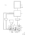
図1は、本発明の実施の形態1にかかる顕微鏡システムの構成の一例を示す概念図である。図2は、本発明の実施の形態1にかかる顕微鏡システムの機能構成を示すブロック図である。なお、図1および図2において、顕微鏡システム1が載置される平面をXY平面とし、XY平面と垂直な方向をZ方向として説明する。
(Embodiment 1)
FIG. 1 is a conceptual diagram showing an example of the configuration of the microscope system according to the first embodiment of the present invention. FIG. 2 is a block diagram illustrating a functional configuration of the microscope system according to the first embodiment of the present invention. 1 and 2, the plane on which the microscope system 1 is placed will be described as an XY plane, and a direction perpendicular to the XY plane will be described as a Z direction.
図1および図2に示すように、顕微鏡システム1は、標本試料Sを観察する顕微鏡装置2と、顕微鏡装置2を駆動制御する顕微鏡制御部3と、顕微鏡装置2を介して標本試料Sを撮像して画像データを生成する撮像装置4と、撮像装置4の駆動を制御する撮像制御部5と、制御端末7を介して撮像装置4が撮像した画像データに対応する画像を表示するとともに、顕微鏡システム1の各種の操作の入力を受け付ける表示入力部6と、顕微鏡制御部3、撮像制御部5および表示入力部6を制御する制御端末7と、を備える。顕微鏡装置2、顕微鏡制御部3、撮像装置4、撮像制御部5、表示入力部6および制御端末7は、データが送受信可能に有線または無線で接続されている。
As shown in FIG. 1 and FIG. 2, the microscope system 1 images the specimen sample S through the
顕微鏡装置2は、標本試料Sが載置される電動ステージ21と、側面視略C字状をなし、電動ステージ21を支持するとともに、レボルバ22を介して対物レンズ23を保持する顕微鏡本体部24と、標本試料Sに光を照射する落射照明用光源25と、を備える。
The
電動ステージ21は、XYZ方向に移動自在に構成されている。電動ステージ21は、モータ211によってXY平面内で移動自在である。電動ステージ21は、顕微鏡制御部3の制御のもと、図示しないXY位置の原点センサによってXY平面における所定の原点位置を検出し、この原点位置を基点としてモータ211の駆動量が制御されることによって、標本試料S上の観察箇所を移動する。電動ステージ21は、観察時のX位置およびY位置に関する位置信号(XY座標)を顕微鏡制御部3に出力する。また、電動ステージ21は、モータ212によってZ方向に移動自在である。電動ステージ21は、顕微鏡制御部3の制御のもと、図示しないZ位置の原点センサによって電動ステージ21のZ方向における所定の原点位置を検出し、この原点位置を基点としてモータ212の駆動量が制御されることによって、所定の高さ範囲内の任意のZ位置に標本試料Sを焦準移動させる。電動ステージ21は、観察時のZ位置に関する位置信号を顕微鏡制御部3に出力する。
The
レボルバ22は、顕微鏡本体部24に対してスライド自在または回転自在に設けられ、対物レンズ23を標本試料Sの上方に配置する。レボルバ22は、ノーズピースや電動レボルバ等を用いて構成される。レボルバ22は、マウンタ221によって倍率(観察倍率)が異なる複数の対物レンズ23を保持する。レボルバ22は、観察光の光路上に挿入されて標本試料Sの観察に用いる対物レンズ23を択一的に切換えるため、マウンタ221を回転自在又は、スライド自在にさせるレボルバモータ222と、レボルバ22の接続状態等を検出するレボルバ検出部223と、を有する。
The
レボルバモータ222は、顕微鏡制御部3の制御のもと、マウンタ221をスライド又は、回転させる。レボルバ検出部223は、レボルバ22が顕微鏡本体部24に接続されていることを検知するレボルバ接続センサ(図示せず)と、対物レンズ23が観察光の光路上に挿入された対物レンズ23の種類を識別するレボルバセンサ(図示せず)と、対物レンズ23が観察光の光路上に挿入されたことを検知する移動完了センサ(図示せず)と、を有する。レボルバ検出部223は、各種センサが検出した検出結果を顕微鏡制御部3へ出力する。
The
対物レンズ23は、たとえば1倍,2倍,4倍の比較的倍率の低い対物レンズ231(以下、「低倍対物レンズ231」という)と、10倍,20倍,40倍の低倍対物レンズ231の倍率に対して高倍率である対物レンズ232(以下、「高倍対物レンズ232」という)とを少なくとも一つずつマウンタ221に装着される。なお、低倍対物レンズ231および高倍対物レンズ232の倍率は一例であり、高倍対物レンズ232が低倍対物レンズ231に対して倍率が高ければよい。
The
顕微鏡本体部24は、ファイバー251を介して落射照明用光源25から出射された照明光L1(以下、「落射照明光L1」という)を集光する照明レンズ241と、落射照明光L1の光路を対物レンズ23の光軸に沿って偏向させるハーフミラー242と、標本試料Sを拡大するズームレンズ部243と、対物レンズ23、ズームレンズ部243およびハーフミラー242を介して入射される標本試料Sの反射光を集光して観察像を結像する結像レンズ244とが内部に設けられている。
The microscope
ズームレンズ部243は、1または複数のレンズからなり、ズーム光学系243aおよびズーム光学系243aと、ズーム光学系243aを光軸に沿って駆動するズーム駆動部243bと、を有する。ズーム駆動部243bは、顕微鏡制御部3の制御のもと、ズーム光学系243aを光軸方向に沿って移動させることにより、ズームレンズ部243の倍率を変更する。
The
落射照明光L1は、照明レンズ241、ハーフミラー242、ズーム光学系243aおよび対物レンズ23を経て標本試料Sに照射される。標本試料Sで反射した反射光L2(以下、「観察光L2」という)は、対物レンズ23、ズーム光学系243a、ハーフミラー242および結像レンズ244を経て撮像装置4に入射する。
The epi-illumination light L1 is applied to the specimen S through the
落射照明用光源25は、ハロゲンランプ、キセノンランプまたはLED(Light Emitting Diode)等によって構成される。落射照明用光源25は、ファイバー251を介して標本試料Sの観察像を形成するための落射照明光L1を顕微鏡本体部24に出射する。
The epi-
顕微鏡制御部3は、CPU(Central Processing Unit)等を用いて構成され、制御端末7の制御のもと、顕微鏡装置2を構成する各部の動作を統括的に制御する。具体的には、顕微鏡制御部3は、レボルバモータ222を駆動することにより、マウンタ221を回転させて観察光L2の光路上に配置する対物レンズ23を切換える切換処理、モータ211またはモータ212を駆動することにより、電動ステージ21の駆動処理、および標本試料Sの観察に伴う顕微鏡装置2の各部の調整を行う調整処理等を行う。また、顕微鏡制御部3は、顕微鏡装置2を構成する各部の状態、たとえば電動ステージ21の位置情報(XY位置、Z位置)およびレボルバ22に装着された対物レンズ23の種類情報等を制御端末7に出力する。
The
撮像装置4は、CCD(Charge Coupled Device)またはCMOS(Complementary Metal Oxide Semiconductor)等の撮像素子41を用いて構成される。撮像装置4は、撮像制御部5の制御のもと、結像レンズ244を経て入射された標本試料Sの観察像を撮像し、カメラケーブルを介して撮像した標本試料Sの画像データを制御端末7へ出力する。
The
撮像制御部5は、CPU等を用いて構成され、撮像装置4の動作を制御する。具体的には、撮像制御部5は、撮像装置4の自動ゲイン制御のON/OFF切換処理、ゲインの設定処理およびフレームレートの設定処理等を行って撮像装置4の撮影動作を制御する。撮像制御部5は、AE処理部51と、AF処理部52と、を有する。
The
AE処理部51は、撮像装置4が生成した画像データに基づいて、撮像装置4の露出条件を自動的に設定する。具体的には、AE処理部51は、制御端末7を介して取得した画像データから輝度を算出し、算出した輝度に基づいて撮像装置4の露出条件、たとえば露光時間を決定することで撮像装置4の自動露出を行う。
The
AF処理部52は、撮像装置4が生成した画像データに基づいて、撮像装置4のピントを自動的に調整する。具体的には、AF処理部52は、画像データに含まれるコントラストを評価し、合焦している合焦位置(焦点位置)を検出することにより、撮像装置4のピントを自動的に調整する。なお、AF処理部52は、画像データに基づいて、電動ステージ21の各Z位置における画像のコントラストを評価することにより、合焦している焦点位置(Z位置)を検出してもよい。
The
表示入力部6は、制御端末7との通信を行う表示通信部61と、画像を表示する表示部62と、外部からの物体の接触に応じた位置信号を出力するタッチパネル63と、を有する。
The
表示通信部61は、制御端末7との通信を行うための通信インターフェースである。表示通信部61は、制御端末7から出力される画像データを表示部62へ出力する。
The
表示部62は、液晶または有機EL(Electro Luminescence)等からなる表示パネルを用いて構成される。表示部62は、表示通信部61を介して入力される標本試料Sを撮像した画像データに対応する画像を表示する。表示部62は、顕微鏡装置2に含まれる複数の電動ユニットの各々の駆動に関する操作情報を表示する。表示部62は、顕微鏡システム1の各種操作情報等を表示する。
The
タッチパネル63は、表示部62の表示画面上に設けられ、外部からの物体の接触位置に応じた入力を受け付ける。具体的には、タッチパネル63は、ユーザが表示部62に表示される操作アイコンに従ってタッチ(接触)した位置を検出し、この検出したタッチ位置に応じた位置信号を制御端末7へ出力する。たとえば、図3に示すように、タッチパネル63は、表示部62が顕微鏡システム1の各種操作情報を画像表示領域A1内で表示することで、グラフィカルユーザインターフェース(GUI)として機能する。一般に、タッチパネルとしては、抵抗膜方式、静電容量方式および光学方式等がある。本実施の形態1では、いずれの方式のタッチパネルであっても適用可能である。
The
制御端末7は、顕微鏡制御部3、撮像制御部5および表示入力部6との通信を行う制御通信部71と、顕微鏡システム1の各種情報を記憶する記憶部73と、顕微鏡システム1の各部の駆動を指示する駆動指示信号の入力を受け付ける入力部72と、顕微鏡システム1の各部を制御する制御部74と、を備える。
The control terminal 7 includes a
制御通信部71は、顕微鏡制御部3、撮像制御部5および表示入力部6それぞれとの通信を行うための通信インターフェースである。また、制御通信部71は、カメラケーブルを介して撮像装置4から出力される画像データを制御部74へ出力する。
The
入力部72は、キーボード、マウス、ジョイスティックおよび各種スイッチ等を用いて構成され、各種スイッチの操作入力に応じた操作信号を制御部74に出力する。 The input unit 72 is configured using a keyboard, a mouse, a joystick, various switches, and the like, and outputs operation signals corresponding to operation inputs of the various switches to the control unit 74.
記憶部73は、制御端末7の内部に固定的に設けられるフラッシュメモリおよびRAM(Random Access Memory)等の半導体メモリを用いて実現される。記憶部73は、顕微鏡システム1に実行させる各種プログラム、プログラムの実行中に使用される各種データを記憶する。また、記憶部73は、制御部74の処理中の情報を一次的に記憶する。記憶部73は、撮像装置4が撮像した画像データを記憶する画像データ記憶部731と、表示入力部6のタッチパネル63から出力される接触位置の入力に応じた位置信号を記憶する位置信号記憶部732と、を有する。なお、記憶部73は、外部から装着されるメモリカード等を用いて構成されてもよい。
The
制御部74は、CPU等を用いて構成され、入力部72およびタッチパネル63からの駆動指示信号、位置信号および切換信号等に応じて顕微鏡システム1を構成する各部に対応する指示やデータの転送等を行って顕微鏡システム1の動作を統括的に制御する。
The control unit 74 is configured using a CPU or the like, and transfers instructions and data corresponding to each unit constituting the microscope system 1 according to a drive instruction signal, a position signal, a switching signal, and the like from the input unit 72 and the
制御部74の詳細な構成について説明する。制御部74は、画像処理部741と、トリミング部742と、駆動制御部743と、表示制御部744と、を有する。
A detailed configuration of the control unit 74 will be described. The control unit 74 includes an
画像処理部741は、制御通信部71を介して入力される画像データに対して、所定の画像処理を施して表示部62で表示する表示画像を生成する。具体的には、画像処理部741は、画像データに対して、オプティカルブラック減算処理、ホワイトバランス調整処理、同時化処理、カラーマトリクス演算処理、γ補正処理、色再現処理およびエッジ強調処理等を含む画像処理を行う。画像処理部741は、画像データを所定の方式、たとえばJPEG(Joint Photographic Experts Group)方式で圧縮し、圧縮した画像データを画像データ記憶部731へ出力する。
The
トリミング部742は、画像処理部741が画像処理を施した画像データに対応する画像から所定の領域を切出してトリミング画像を生成する。
The
駆動制御部743は、タッチパネル63から位置信号が出力されて、この位置信号の出力が停止したとき、位置信号記憶部732が記憶するタッチパネル63から出力された位置信号を取得し、この位置信号に基づいて、顕微鏡装置2を構成する複数の電動ユニットの各々を駆動する駆動信号を複数の電動ユニットに出力する。具体的には、駆動制御部743は、電動ステージ21に駆動信号を出力する。
When the position signal is output from the
表示制御部744は、表示部62の表示態様を制御する。具体的には、表示制御部744は、画像データ記憶部731が記憶する複数の画像データの各々の画像を表示部62に表示させる。表示制御部744は、顕微鏡システム1の各々の動作に関する操作情報、たとえば、電動ステージ21の操作情報等を表示部62に表示させる。
The
このように構成された顕微鏡システム1は、制御部74の制御のもと、撮像装置4で撮像された標本試料Sの画像データを表示部62に表示することによってユーザに標本試料Sの画像を観察させることができる。さらに、顕微鏡システム1は、タッチパネル63から入力される位置信号に基づいて、制御部74が顕微鏡システム1の各部に指示信号や駆動信号を出力することにより、顕微鏡装置2および撮像装置4が駆動する。
The microscope system 1 configured in this manner displays an image of the sample sample S on the
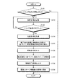
つぎに、顕微鏡システム1が行う動作について説明する。図4は、本実施の形態1にかかる顕微鏡システム1が行う処理の概要を示すフローチャートである。なお、以下においては、顕微鏡装置2の電動ユニットとして電動ステージ21を例に説明する。
Next, operations performed by the microscope system 1 will be described. FIG. 4 is a flowchart illustrating an outline of processing performed by the microscope system 1 according to the first embodiment. In the following, the
図4に示すように、駆動制御部743は、タッチパネル63に対し、ドラッグ操作が開始されたか否かを判断する(ステップS101)。具体的には、図5に示すように、駆動制御部743は、ユーザがタッチパネル63にタッチ(図5(a))することにより、タッチパネル63から接触位置を示す位置信号が入力されたか否かを判断する。タッチパネル63に対し、ドラッグ操作が開始されたと駆動制御部743が判断した場合(ステップS101:Yes)、顕微鏡システム1は、ステップS102へ移行する。一方、タッチパネル63を介してドラッグ操作が開始されていないと駆動制御部743が判断した場合(ステップS101:No)、顕微鏡システム1は、本処理を終了する。
As illustrated in FIG. 4, the
続いて、駆動制御部743は、タッチパネル63から出力される位置信号を位置信号記憶部732に記憶する(ステップS102)。この場合、駆動制御部743は、図5(b)に示すように、ユーザがタッチパネル63にタッチし続けているとき、所定の周期毎、たとえば1パルス毎に、タッチパネル63から出力される位置信号を時系列に沿って位置信号記憶部732に記憶する。
Subsequently, the
その後、駆動制御部743は、タッチパネル63に対し、ドラッグ操作が終了したか否かを判断する(ステップS103)。具体的には、図5に示すように、駆動制御部743は、ユーザがタッチパネル63から指を離反(図5(b)→図5(c))することにより、タッチパネル63から位置信号が停止したか否かを判断する。タッチパネル63に対し、ドラッグ操作が終了していないと駆動制御部743が判断した場合(ステップS103:No)、顕微鏡システム1は、ステップS102へ戻る。一方、タッチパネル63に対し、ドラッグ操作が終了したと駆動制御部743が判断した場合(ステップS103:Yes)、顕微鏡システム1は、ステップS104へ移行する。
Thereafter, the
続いて、駆動制御部743は、位置信号記憶部732に記憶された位置信号を取得し(ステップS104)、取得した位置信号に含まれるドラッグ操作の終了時の座標と開始時の座標とに基づいて、指がタッチパネル63上で移動した移動距離と移動方向を算出する(ステップS105)。具体的には、制御部74は、ユーザが指でタッチパネル63に最初にタッチした位置である開始位置(始点)と、ユーザが指をタッチパネル63から離反させた終了位置(終点)とを結ぶ直線に基づいて、指がタッチパネル63上で移動した移動距離と移動方向を算出する。
Subsequently, the
その後、駆動制御部743は、算出した移動距離および移動方向に応じて、電動ステージ21を駆動する駆動信号を顕微鏡制御部3に出力する(ステップS106)。なお、駆動信号には、電動ステージ21を駆動する駆動方向および駆動量が含まれる。
Thereafter, the
続いて、顕微鏡制御部3は、駆動制御部743から入力された駆動信号に基づいて、モータ211を駆動することにより、電動ステージ21を駆動し(ステップS107)、電動ステージ21の移動完了を示す移動完了信号を制御端末7へ出力する(ステップS108)。
Subsequently, the
その後、制御部74は、撮像制御部5に撮影指示信号を出力することにより、撮像装置4に電動ステージ21の移動後の標本試料Sを撮像させて画像データを生成させることにより、表示部62が表示する画像を電動ステージ21移動後の画像に更新する(ステップS109)。具体的には、図5(d)に示すように、表示部62が表示する画像を電動ステージ21移動後の画像に更新する。これにより、ユーザは、タッチパネル63で操作した標本試料S上の所望の観察箇所を確認することができる。
Thereafter, the control unit 74 outputs an imaging instruction signal to the
以上説明した本発明の実施の形態1によれば、駆動制御部743がタッチパネル63から位置信号が出力され、この位置信号の出力が停止したとき、位置信号記憶部732に記憶されるタッチパネル63から出力された位置信号を取得し、この位置信号に基づいて、顕微鏡装置2の電動ステージ21を駆動する駆動信号を出力する。この結果、ユーザが所望する場所に電動ステージ21を移動させることができる。
According to the first embodiment of the present invention described above, when the
また、本発明の実施の形態1によれば、駆動制御部743がタッチパネル63から出力される位置信号を位置信号記憶部732に一時的に記憶し、ユーザによる操作が終了してから電動ステージ21の駆動量を算出するので、制御ロジックを簡易にすることができる。
Further, according to the first embodiment of the present invention, the
(実施の形態1の変形例1)
上述した実施の形態1において、駆動制御部743は、ユーザがタッチパネル63から指を離反することにより、タッチパネル63から位置信号が停止したか否かを判断し、ドラッグ操作が終了したか否かを判断していたが、たとえばタッチパネル63から出力される位置信号が一定時間、略同じ位置を示す場合、タッチパネル63による操作が終了したと判断し、位置信号記憶部732が記憶する位置信号を取得して駆動信号を顕微鏡制御部3に出力することも可能である。
(Modification 1 of Embodiment 1)
In the first embodiment described above, the
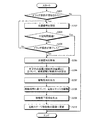
図6は、本実施の形態1の変化例1にかかる顕微鏡システム1が行う処理の概要を示すフローチャートである。なお、以下においては、顕微鏡装置2の電動ユニットとして電動ステージ21を例に説明する。
FIG. 6 is a flowchart illustrating an outline of processing performed by the microscope system 1 according to the first modification of the first embodiment. In the following, the
図6に示すように、ステップS201〜ステップS202は、図4のステップS101〜ステップS102それぞれに対応する。 As shown in FIG. 6, steps S201 to S202 correspond to steps S101 to S102 of FIG.
ステップS203において、駆動制御部743は、タッチパネル63から出力される位置信号が一定時間(たとえば1秒)ほぼ同じタッチパネル63の位置を示しているか否かを判断する。タッチパネル63から出力される位置信号が一定時間略同じ位置を示していると制御部74が判断した場合(ステップS203:Yes)、顕微鏡システム1は、ステップS205へ移行する。一方、タッチパネル63から出力される位置情報が一定時間ほぼ同じ位置を示していないと制御部74が判断した場合(ステップS203:No)、顕微鏡システム1は、ステップS204へ移行する。
In step S203, the
ステップS204〜ステップS210は、図4のステップS103〜ステップS109それぞれに対応する。 Steps S204 to S210 correspond to steps S103 to S109 in FIG.
以上説明した本発明における実施の形態1の変形例1によれば、駆動制御部743がタッチパネル63から出力される位置信号が一定時間を超えてタッチパネル63の略同じ位置を示す場合、タッチパネル63による操作が終了したと判断し、位置信号記憶部732に記憶された位置信号を取得し、この位置信号に基づいて、顕微鏡装置2の電動ステージ21を駆動する駆動信号を出力する。この結果、ユーザの操作に追従して徐々に電動ステージ21を駆動することができ、ユーザが所望する位置まで電動ステージ21を早く移動させることができる。
According to the first modification of the first embodiment of the present invention described above, when the position signal output from the
(実施の形態1の変形例2)
上述した実施の形態1において、電動ユニットとして電動ステージ21のみの動作を説明していたが、駆動制御部743がタッチパネル63から位置信号が出力されて停止したとき、電動ステージ21の駆動と撮像装置4のピント位置の調整との制御を同時に行ってもよい。この場合、駆動制御部743は、タッチパネル63から出力される位置信号が停止したとき、位置信号記憶部732が記憶する位置信号を取得し、取得した位置信号に基づいて、電動ステージ21の駆動信号および撮像装置4のピント位置を調整する指示信号をそれぞれ生成する。その後、駆動制御部743は、顕微鏡制御部3および撮像制御部5にそれぞれ駆動信号および指示信号を出力する。
(
In Embodiment 1 described above, the operation of only the
このように、本実施の形態1の変形例2によれば、ユーザは、タッチパネル63に対して一つの動作のみで、標本試料S上の所望の観察位置に移動させることができるとともに、観察位置に撮像装置4のピントがあった画像を確認することができる。
As described above, according to the second modification of the first embodiment, the user can move the
(実施の形態1の変形例3)
上述した実施の形態1において、電動ステージ21におけるXY平面の移動を説明していたが、電動ステージ21のZ方向の駆動制御を行ってもよい。この場合、駆動制御部743は、タッチパネル63から出力される位置信号が出力され、この位置信号の出力が停止したとき、タッチパネル63による操作が終了したと判断し、位置信号記憶部732が記憶する位置信号を取得し、取得した位置信号に基づいて、電動ステージ21のZ方向の駆動を指示する駆動信号を生成する。その後、駆動制御部743は、顕微鏡制御部3に駆動信号を出力する。
(
In Embodiment 1 described above, the movement of the XY plane in the
このように、本実施の形態1の変形例3によれば、駆動制御部743がタッチパネル63から出力される位置信号を位置信号記憶部732に一時的に記憶し、ユーザによる操作が終了してから電動ステージ21のZ方向の駆動量を算出するので、制御ロジックを簡易にすることができる。さらに、ユーザの操作に追従して電動ステージ21をZ方向に滑らかに移動することができる。
Thus, according to the third modification of the first embodiment, the
(実施の形態2)
つぎに、本発明の実施の形態2について説明する。本発明の実施の形態2は、上述した実施の形態1にかかる顕微鏡システムによる動作のみ異なり、顕微鏡システムの構成は上述した実施の形態1にかかる顕微鏡システムと同様の構成を有する。このため、以下においては、本発明の実施の形態2にかかる顕微鏡システムによる動作のみ説明する。
(Embodiment 2)
Next, a second embodiment of the present invention will be described. The second embodiment of the present invention differs only in the operation of the microscope system according to the first embodiment described above, and the configuration of the microscope system has the same configuration as the microscope system according to the first embodiment described above. For this reason, only the operation of the microscope system according to the second embodiment of the present invention will be described below.
図7は、本実施の形態2にかかる顕微鏡システム1が行う処理の概要を示すフローチャートである。 FIG. 7 is a flowchart illustrating an outline of processing performed by the microscope system 1 according to the second embodiment.
図7に示すように、ステップS301〜ステップS302は、図4のステップS101〜ステップS102それぞれに対応する。 As shown in FIG. 7, steps S301 to S302 correspond to steps S101 to S102 of FIG.
ステップS303において、駆動制御部743は、撮像装置4の撮像動作を指示する指示信号を撮像制御部5に出力することにより、撮像装置4に画像データを生成させ、この画像データに対応するライブ画像を取得する。
In step S303, the
続いて、トリミング部742は、ライブ画像に対し、タッチパネル63から出力される位置信号に応じて、表示部62で表示するための表示画像を生成する(ステップS304)。具体的には、トリミング部742は、タッチパネル63から出力される位置信号に対応する表示部62の表示領域において、タッチパネル63から出力される位置信号を中心とする領域をライブ画像から切出して表示画像としてのトリミング画像を生成する。
Subsequently, the
その後、表示制御部744は、トリミング部742が生成した表示画像を表示部62に表示させる(ステップS305)。
Thereafter, the
続いて、駆動制御部743は、ドラッグ操作が終了したか否かを判断する(ステップS306)。ドラッグ操作が終了したと駆動制御部743が判断した場合(ステップS306:Yes)、顕微鏡システム1は、ステップS307へ移行する。一方、ドラッグ操作が終了していないと駆動制御部743が判断した場合(ステップS306:No)、顕微鏡システム1は、ステップS302へ戻る。
Subsequently, the
ステップS307〜ステップS312は、図4のステップS103〜ステップS109それぞれに対応する。 Steps S307 to S312 correspond to steps S103 to S109 in FIG.
以上説明した本発明の実施の形態2によれば、駆動制御部743がタッチパネル63から位置信号が出力されている場合、撮像装置4の撮像動作を指示する指示信号を撮像制御部5に出力することにより、撮像装置4に画像データを生成させ、トリミング部742がタッチパネル63から出力される位置信号に応じて画像データに対応する画像から表示画像としてのトリミング画像を所定間隔毎に生成し、表示制御部744がトリミング部742によって所定時間ごとに生成されたタッチパネル63から出力される位置信号に応じた表示画像としてのトリミング画像を表示部62に更新して表示する。この結果、ユーザがタッチパネル63に対して行った操作に追従して仮想的に画像のみを更新するので、ユーザは、敏速に標本試料Sの観察を行うことができる。
According to the second embodiment of the present invention described above, when the
(実施の形態3)
つぎに、本発明の実施の形態3について説明する。本発明の実施の形態3にかかる顕微鏡システムは、上述した実施の形態にかかる顕微鏡システムによる動作のみ異なり、顕微鏡システムの構成は上述した実施の形態にかかる顕微鏡システムと同様の構成を有する。このため、以下においては、本発明の実施の形態2にかかる顕微鏡システムによる動作のみ説明する。
(Embodiment 3)
Next, a third embodiment of the present invention will be described. The microscope system according to the third embodiment of the present invention is different only in operation by the microscope system according to the above-described embodiment, and the configuration of the microscope system has the same configuration as the microscope system according to the above-described embodiment. For this reason, only the operation of the microscope system according to the second embodiment of the present invention will be described below.
図8は、本実施の形態3にかかる顕微鏡システム1が行う処理の概要を示すフローチャートである。なお、本実施の形態3においては、顕微鏡装置2の電動ユニットとしてズームレンズ部243を例に説明する。
FIG. 8 is a flowchart illustrating an outline of processing performed by the microscope system 1 according to the third embodiment. In the third embodiment, a
図8に示すように、駆動制御部743は、タッチパネル63に対し、ピンチ操作が開始されたか否かを判断する(ステップS401)。具体的には、図9に示すように、制御部74は、ユーザがタッチパネル63の2箇所にタッチ(図9(a))することにより、タッチパネル63から異なる接触位置を示す2つの位置信号が出力されたか否かを判断する。タッチパネル63に対し、ピンチ操作が開始されたと駆動制御部743が判断した場合(ステップS401:Yes)、顕微鏡システム1はステップS402へ移行する。一方、タッチパネル63を介してピンチ操作が開始されていないと駆動制御部743が判断した場合(ステップS401:No)、顕微鏡システム1は、本処理を終了する。
As illustrated in FIG. 8, the
続いて、駆動制御部743は、タッチパネル63から出力される二つの位置信号に対応したタッチパネル63の位置信号を位置信号記憶部732に記憶する(ステップS402)。
Subsequently, the
その後、駆動制御部743は、タッチパネル63に対し、ピンチ操作が終了したか否かを判断する(ステップS403)。具体的には、図9に示すように、駆動制御部743は、ユーザがどちらか一方の指または両方の指をタッチパネル63から離反(図9(b)→図9(c))することにより、タッチパネル63から一方または二つの位置信号の出力が停止したか否かを判断することにより、ピンチ操作が終了したか否かを判断する。タッチパネル63に対し、ピンチ操作が終了したと駆動制御部743が判断した場合(ステップS403:Yes)、顕微鏡システム1は、ステップS404へ移行する。一方、ピンチ操作が終了していないと駆動制御部743が判断した場合(ステップS403:No)、顕微鏡システム1は、ステップS402へ戻る。
Thereafter, the
ステップS404において、駆動制御部743は、位置信号記憶部732が記憶する位置情報を取得し、取得した位置情報に基づいて、ズームレンズ部243によるズーム倍率を算出する(ステップS405)。具体的には、駆動制御部743は、ピンチ操作の開始時の二つの位置を結ぶ直線と、ピンチ操作の終了時の二つの位置を結ぶ直線との比率に基づいて、ズームレンズ部243によるズーム率を算出する。
In step S404, the
続いて、駆動制御部743は、算出したズーム倍率に応じたズーム駆動指示信号を顕微鏡制御部3に出力する(ステップS406)。
Subsequently, the
その後、顕微鏡制御部3は、ズーム駆動指示信号に基づいて、ズーム駆動部243bを駆動することにより、ズーム光学系243aを光軸に沿って駆動し(ステップS407)、ズーム光学系243aの駆動が完了した際に駆動完了信号を制御部74に出力する(ステップS408)。
Thereafter, the
続いて、駆動制御部743は、撮像制御部5に撮影指示信号を出力することにより、撮像装置4にズーム後の標本試料Sを撮像させて画像データを生成させて表示部62が表示する画像をズーム後の画像に更新する(ステップS409)。具体的には、図9(d)に示すように、表示部62がピンチ操作により拡大された標本試料Sの画像を表示する。その後、顕微鏡システム1は、本処理を終了する。
Subsequently, the
以上説明した本発明の実施の形態3によれば、駆動制御部743がタッチパネル63から位置信号が出力され、この位置信号の出力が停止したとき、位置信号記憶部732に記憶された位置信号を取得し、この位置信号に基づいて、顕微鏡装置2のズームレンズ部243を駆動する駆動信号を出力する。この結果、ユーザが標本試料Sを所望する倍率に拡大して観察することができる。
According to the third embodiment of the present invention described above, when the
なお、本発明の実施の形態3では、ピンチ操作として標本試料Sを拡大するピンチアウト操作を例に説明したが、標本試料Sを縮小するピンチイン操作であっても本発明を適用することができる。ここで、ピンチアウト操作とは、ユーザがタッチパネル63に対して異なる位置でタッチした2つのタッチ位置をタッチパネル63の外縁に向けて2つのタッチ位置の距離を広げることである。また、ピンチイン操作とは、ユーザがタッチパネル63に対して異なる位置でタッチした2つのタッチ位置をタッチパネル63の中心に向けて2つのタッチ位置の距離を縮めることである。
In the third embodiment of the present invention, the pinch-out operation for enlarging the specimen sample S is described as an example of the pinch operation. However, the present invention can be applied to a pinch-in operation for reducing the specimen sample S. . Here, the pinch-out operation is to increase the distance between the two touch positions by directing the two touch positions where the user touches the
また、本発明の実施の形態3では、駆動制御部743がピンチ操作に応じて拡大または縮小していたが、たとえばタッチパネル63から出力される位置信号の軌跡に応じて、標本試料Sの拡大または縮小を行ってもよい。
In the third embodiment of the present invention, the
また、本発明の実施の形態3では、駆動制御部743がズームレンズ部243によって標本試料Sを拡大した後に、表示部62が表示する画像を更新していたが、上述した実施の形態と同様に、タッチパネル63から出力される位置信号に応じて、トリミング部742に表示画像としてのトリミング画像を生成させることにより、画像を更新してもよい。この場合、駆動制御部743は、ピンチ操作に応じて、トリミング部742が観察画像から切出して生成するトリミング画像の大きさを指示することにより、仮想的に標本試料Sを拡大した画像をユーザに観察させることができる。
In the third embodiment of the present invention, the image displayed on the
また、本発明の実施の形態3では、駆動制御部743は、タッチパネル73から位置信号が出力された、この位置信号の出力が停止したとき、ズームレンズ部243に駆動信号を出力していたが、たとえば、電動ステージ21およびズームレンズ部243それぞれに駆動信号を同時に出力してもよい。これにより、ユーザは、一つの動作で標本試料Sの所望の位置と倍率で観察することができる。
In
なお、上述した実施の形態では、顕微鏡装置、撮像装置、表示入力部および制御端末を備えた顕微鏡システムを例に説明したが、たとえば標本試料を拡大する対物レンズ、対物レンズを介して標本試料を撮像する撮像機能、および画像を表示する表示機能を備えた撮像装置、たとえばビデオマイクロスコープ等であっても、本発明を適用することができる。 In the above-described embodiment, the microscope system including the microscope device, the imaging device, the display input unit, and the control terminal has been described as an example. The present invention can also be applied to an imaging apparatus having an imaging function for imaging and a display function for displaying an image, such as a video microscope.
また、上述した実施の形態では、顕微鏡装置として正立型顕微鏡装置を例に説明したが、たとえば倒立型顕微鏡装置であっても本発明を適用することができる。さらに、顕微鏡装置を組み込んだライン装置といった各種システムにも、本発明を適用することができる。 In the above-described embodiment, the upright microscope apparatus is described as an example of the microscope apparatus. However, the present invention can be applied to an inverted microscope apparatus, for example. Furthermore, the present invention can be applied to various systems such as a line apparatus incorporating a microscope apparatus.
また、上述した実施の形態では、表示入力部と制御端末とが別々に構成されていたが、たとえば表示入力部と制御端末とが一体的に形成された携帯型端末であってもよい。 In the above-described embodiment, the display input unit and the control terminal are separately configured. However, for example, a portable terminal in which the display input unit and the control terminal are integrally formed may be used.
1 顕微鏡システム
2 顕微鏡装置
3 顕微鏡制御部
4 撮像装置
5 撮像制御部
6 表示入力部
7 制御端末
21 電動ステージ
22 レボルバ
23 対物レンズ
24 顕微鏡本体部
25 落射照明用光源
41 撮像素子
51 AE処理部
52 AF処理部
61 表示通信部
62 表示部
63 タッチパネル
71 制御通信部
72 入力部
73 記憶部
74 制御部
211,212 モータ
241 照明レンズ
242 ハーフミラー
243 ズームレンズ部
243a ズーム光学系
243b ズーム駆動部
244 結像レンズ
731 画像データ記憶部
732 位置信号記憶部
741 画像処理部
742 トリミング部
743 駆動制御部
744 表示制御部
DESCRIPTION OF SYMBOLS 1
Claims (9)
前記標本試料を撮像した画像データに対応する画像を表示するとともに、前記複数の電動ユニットの各々の駆動に関する操作情報を表示する表示部と、
前記表示部の表示画面上に設けられ、外部からの物体の接触位置に応じた入力を受け付けるタッチパネルと、
前記タッチパネルから出力される前記接触位置の入力に応じた位置信号を記憶する記憶部と、
前記タッチパネルから前記位置信号が出力されて、該位置信号の出力が停止したとき、前記記憶部に記憶された前記位置信号を取得し、該位置信号に基づいて、前記複数の電動ユニットの各々を駆動するそれぞれの駆動信号を前記複数の電動ユニットに出力する駆動制御部と、
を備えたことを特徴とする顕微鏡システム。 A microscope system for observing a specimen by driving each of a plurality of electric units included in a microscope apparatus,
A display unit that displays an image corresponding to image data obtained by imaging the specimen and displays operation information related to driving of each of the plurality of electric units;
A touch panel that is provided on a display screen of the display unit and receives an input according to a contact position of an object from outside;
A storage unit for storing a position signal corresponding to the input of the contact position output from the touch panel;
When the position signal is output from the touch panel and the output of the position signal is stopped, the position signal stored in the storage unit is acquired, and each of the plurality of electric units is operated based on the position signal. A drive control unit for outputting each drive signal to be driven to the plurality of electric units;
A microscope system comprising:
前記駆動制御部は、前記開始位置と前記終了位置とに基づいて、前記複数の電動ユニットの各々の駆動量を算出することを特徴とする請求項1または2に記載の顕微鏡システム。 The storage unit stores a start position where the object first contacts the touch panel and an end position where the object is away from the touch panel.
The microscope system according to claim 1, wherein the drive control unit calculates a drive amount of each of the plurality of electric units based on the start position and the end position.
前記駆動制御部は、前記電動ステージを駆動する駆動信号および前記ズームレンズ部を駆動する駆動信号をそれぞれ同時に出力することを特徴とする請求項1〜4のいずれか一つに記載の顕微鏡システム。 The electric unit has an electric stage on which the specimen sample is mounted and a plane that is movable, and a zoom lens unit that enlarges the specimen sample.
The microscope system according to claim 1, wherein the drive control unit simultaneously outputs a drive signal for driving the electric stage and a drive signal for driving the zoom lens unit.
前記撮像装置が生成した前記観察画像データに対応する観察画像を前記表示部に表示させる表示制御部と、
をさらに備え、
前記駆動制御部は、前記タッチパネルから前記位置信号が出力されている場合、前記撮像装置に撮影を指示する撮影指示信号を出力し、
前記表示制御部は、前記観察画像を所定時間ごとに更新して前記表示部に表示させることを特徴とする請求項1〜6のいずれか一つに記載の顕微鏡システム。 An imaging device that images the specimen and generates observation image data of the specimen;
A display control unit that causes the display unit to display an observation image corresponding to the observation image data generated by the imaging device;
Further comprising
When the position signal is output from the touch panel, the drive control unit outputs a shooting instruction signal that instructs the imaging device to perform shooting,
The microscope system according to claim 1, wherein the display control unit updates the observation image every predetermined time and displays the updated image on the display unit.
前記駆動制御部は、前記タッチパネルから出力される前記位置信号に基づいて、前記トリミング部が前記観察画像から前記表示画像を切出す位置を指示する指示信号を出力することを特徴とする請求項7に記載の顕微鏡システム。 A trimming unit that generates a display image by cutting out an area corresponding to the display area of the display unit from the observation image;
The said drive control part outputs the instruction | indication signal which instruct | indicates the position which the said trimming part cuts out the said display image from the said observation image based on the said position signal output from the said touch panel. The microscope system described in 1.
前記表示制御部は、前記トリミング部が生成した前記表示画像を前記表示部に表示させることを特徴とする請求項8に記載の顕微鏡システム。 The trimming unit generates the display image every predetermined time when the touch panel continues to output the position signal,
The microscope system according to claim 8, wherein the display control unit causes the display unit to display the display image generated by the trimming unit.
Priority Applications (2)
| Application Number | Priority Date | Filing Date | Title |
|---|---|---|---|
| JP2011211625A JP2013072995A (en) | 2011-09-27 | 2011-09-27 | Microscope system |
| US13/618,258 US8922639B2 (en) | 2011-09-27 | 2012-09-14 | Microscope system |
Applications Claiming Priority (1)
| Application Number | Priority Date | Filing Date | Title |
|---|---|---|---|
| JP2011211625A JP2013072995A (en) | 2011-09-27 | 2011-09-27 | Microscope system |
Publications (1)
| Publication Number | Publication Date |
|---|---|
| JP2013072995A true JP2013072995A (en) | 2013-04-22 |
Family
ID=48477549
Family Applications (1)
| Application Number | Title | Priority Date | Filing Date |
|---|---|---|---|
| JP2011211625A Pending JP2013072995A (en) | 2011-09-27 | 2011-09-27 | Microscope system |
Country Status (1)
| Country | Link |
|---|---|
| JP (1) | JP2013072995A (en) |
Cited By (1)
| Publication number | Priority date | Publication date | Assignee | Title |
|---|---|---|---|---|
| JP2022516855A (en) * | 2018-12-27 | 2022-03-03 | ライカ インストゥルメンツ (シンガポール) プライヴェット リミテッド | Digital microscopy systems, methods and computer programs for operating digital microscopy systems |
Citations (7)
| Publication number | Priority date | Publication date | Assignee | Title |
|---|---|---|---|---|
| JPH08223563A (en) * | 1995-02-15 | 1996-08-30 | Meitec Corp | Controlling system for sample board for observing device |
| JPH09197287A (en) * | 1996-01-23 | 1997-07-31 | Nikon Corp | Electric microscope |
| JP2008145169A (en) * | 2006-12-07 | 2008-06-26 | Xanavi Informatics Corp | Navigation apparatus |
| JP2009101061A (en) * | 2007-10-25 | 2009-05-14 | Copcom Co Ltd | Operation control device, program for realizing this operation control device, and recording medium recording this program |
| JP2010093516A (en) * | 2008-10-08 | 2010-04-22 | Nec Corp | Mobile information terminal and operation control method for the same, and program |
| JP2010122856A (en) * | 2008-11-19 | 2010-06-03 | Sony Corp | Image processing apparatus, image displaying method, and image display program |
| JP2011118188A (en) * | 2009-12-04 | 2011-06-16 | Olympus Corp | Microscope controller and microscope system provided with microscope controller |
-
2011
- 2011-09-27 JP JP2011211625A patent/JP2013072995A/en active Pending
Patent Citations (7)
| Publication number | Priority date | Publication date | Assignee | Title |
|---|---|---|---|---|
| JPH08223563A (en) * | 1995-02-15 | 1996-08-30 | Meitec Corp | Controlling system for sample board for observing device |
| JPH09197287A (en) * | 1996-01-23 | 1997-07-31 | Nikon Corp | Electric microscope |
| JP2008145169A (en) * | 2006-12-07 | 2008-06-26 | Xanavi Informatics Corp | Navigation apparatus |
| JP2009101061A (en) * | 2007-10-25 | 2009-05-14 | Copcom Co Ltd | Operation control device, program for realizing this operation control device, and recording medium recording this program |
| JP2010093516A (en) * | 2008-10-08 | 2010-04-22 | Nec Corp | Mobile information terminal and operation control method for the same, and program |
| JP2010122856A (en) * | 2008-11-19 | 2010-06-03 | Sony Corp | Image processing apparatus, image displaying method, and image display program |
| JP2011118188A (en) * | 2009-12-04 | 2011-06-16 | Olympus Corp | Microscope controller and microscope system provided with microscope controller |
Cited By (1)
| Publication number | Priority date | Publication date | Assignee | Title |
|---|---|---|---|---|
| JP2022516855A (en) * | 2018-12-27 | 2022-03-03 | ライカ インストゥルメンツ (シンガポール) プライヴェット リミテッド | Digital microscopy systems, methods and computer programs for operating digital microscopy systems |
Similar Documents
| Publication | Publication Date | Title |
|---|---|---|
| US8922639B2 (en) | Microscope system | |
| JP5875812B2 (en) | Microscope system and illumination intensity adjustment method | |
| JP5875813B2 (en) | Microscope system | |
| JP6112819B2 (en) | Electronic device, driving method and program | |
| JP5620142B2 (en) | Imaging apparatus and imaging method | |
| JP5893314B2 (en) | Display device and microscope system | |
| JP2015197623A (en) | Microscope system | |
| JP2008099874A (en) | Endoscope processor and endoscope system | |
| US20050105174A1 (en) | Microscope system | |
| TW202002606A (en) | Image-capturing device and method for operating the same | |
| JP6238574B2 (en) | Observation device | |
| JP5860649B2 (en) | Microscope system | |
| JP6300974B2 (en) | microscope | |
| JP2013072995A (en) | Microscope system | |
| JP6150504B2 (en) | Imaging system | |
| JP5893315B2 (en) | Microscope system | |
| JP6834988B2 (en) | Control device | |
| JP5904737B2 (en) | Microscope system | |
| JP2012150142A (en) | Microscope control apparatus, microscope system and control method thereof | |
| JP5881356B2 (en) | Microscope system | |
| JP6061614B2 (en) | Microscope system | |
| JP6013100B2 (en) | Imaging apparatus and microscope system | |
| JP6173032B2 (en) | Microscope system | |
| JP6104704B2 (en) | microscope | |
| JP2011248091A (en) | Microscope apparatus and recording medium |
Legal Events
| Date | Code | Title | Description |
|---|---|---|---|
| A621 | Written request for application examination |
Free format text: JAPANESE INTERMEDIATE CODE: A621 Effective date: 20140909 |
|
| A977 | Report on retrieval |
Free format text: JAPANESE INTERMEDIATE CODE: A971007 Effective date: 20150610 |
|
| A131 | Notification of reasons for refusal |
Free format text: JAPANESE INTERMEDIATE CODE: A131 Effective date: 20150707 |
|
| A521 | Written amendment |
Free format text: JAPANESE INTERMEDIATE CODE: A523 Effective date: 20150826 |
|
| A02 | Decision of refusal |
Free format text: JAPANESE INTERMEDIATE CODE: A02 Effective date: 20160209 |