JP2013076366A - Common rail engine - Google Patents
Common rail engine Download PDFInfo
- Publication number
- JP2013076366A JP2013076366A JP2011216725A JP2011216725A JP2013076366A JP 2013076366 A JP2013076366 A JP 2013076366A JP 2011216725 A JP2011216725 A JP 2011216725A JP 2011216725 A JP2011216725 A JP 2011216725A JP 2013076366 A JP2013076366 A JP 2013076366A
- Authority
- JP
- Japan
- Prior art keywords
- engine
- injection
- wires
- exhaust
- actuators
- Prior art date
- Legal status (The legal status is an assumption and is not a legal conclusion. Google has not performed a legal analysis and makes no representation as to the accuracy of the status listed.)
- Pending
Links
Images





Landscapes
- Fuel-Injection Apparatus (AREA)
- Electrical Control Of Air Or Fuel Supplied To Internal-Combustion Engine (AREA)
Abstract
【課題】センサの誤検出を抑制することができるコモンレール式エンジンを提供する。
【解決手段】この課題解決のため、複数の燃料インジェクタの噴射アクチュエータ1〜4にそれぞれ電線1a〜4aを接続し、各電線1a〜4aを介して制御手段5から各噴射アクチュエータ1〜4に電気信号を送信し、この電気信号で各噴射アクチュエータ1〜4の作動を制御して、各燃料インジェクタから各気筒に燃料を噴射するようにしたコモンレール式エンジンにおいて、噴射アクチュエータ1〜4の各電線1a〜4aをセンサ11〜14,21〜24,28,29の電線11a〜14a,21a〜24a,28a,29aとは別に束ね、束ねた噴射アクチュエータ1〜4の電線1a〜4aからセンサ11〜14,21〜24,28,29の電線11a〜14a,21a〜24a,28a,29aを分離させた。
【選択図】図7A common rail engine capable of suppressing erroneous detection of a sensor is provided.
To solve this problem, electric wires 1a to 4a are connected to injection actuators 1 to 4 of a plurality of fuel injectors, respectively, and electric power is supplied from a control means 5 to the injection actuators 1 to 4 via the electric wires 1a to 4a. In the common rail engine in which a signal is transmitted and the operation of each of the injection actuators 1 to 4 is controlled by this electric signal to inject fuel into each cylinder from each fuel injector, each electric wire 1a of the injection actuators 1 to 4 -4a are bundled separately from the wires 11a-14a, 21a-24a, 28a, 29a of the sensors 11-14, 21-24, 28, 29, and the sensors 11-14 from the wires 1a-4a of the bundled injection actuators 1-4. , 21 to 24, 28, and 29 are separated from the wires 11a to 14a, 21a to 24a, 28a, and 29a.
[Selection] Figure 7
Description
本発明は、コモンレール式エンジンに関し、詳しくは、センサの誤検出を抑制することができるコモンレール式エンジンに関する。 The present invention relates to a common rail engine, and more particularly, to a common rail engine that can suppress erroneous detection of a sensor.
従来、コモンレール式エンジンとして、複数の燃料インジェクタの噴射アクチュエータにそれぞれ電線を接続し、各電線を介して制御手段から各噴射アクチュエータに電気信号を送信し、この電気信号で各噴射アクチュエータの作動を制御して、各燃料インジェクタから各気筒に燃料を噴射するものがある(例えば、特許文献1参照)。
この種のエンジンによれば、燃料インジェクタからの燃料の噴射タイミングと噴射量を調節して、高いエンジン出力と排気の清浄化とを図ることができる利点がある。
しかし、この従来技術では、複数の噴射アクチュエータの各電線とセンサの電線とが一くくりに束ねられていたため、問題がある。
Conventionally, as a common rail engine, electric wires are connected to the injection actuators of a plurality of fuel injectors, and electric signals are transmitted from the control means to the injection actuators via the electric wires, and the operation of each injection actuator is controlled by this electric signal. Some fuel injectors inject fuel into each cylinder (see, for example, Patent Document 1).
According to this type of engine, there is an advantage that high engine output and exhaust purification can be achieved by adjusting the injection timing and injection amount of fuel from the fuel injector.
However, this conventional technique has a problem because the electric wires of the plurality of jetting actuators and the electric wires of the sensor are bundled together.
《問題》 センサの誤検出が起こりやすい
複数の噴射アクチュエータの各電線とセンサの電線とが一くくりに束ねられていたため、複数の噴射アクチュエータの各電線で送信される高電圧の電気信号で、センサの電線で送信される低電圧の電気信号が乱されることがあり、センサの誤検出が起こりやすい。
<Problem> Sensor misdetection is likely to occur. Since the wires of the multiple injection actuators and the wires of the sensor were bundled together, the high voltage electrical signal transmitted by the wires of the multiple injection actuators The low-voltage electric signal transmitted by the electric wire may be disturbed, and sensor misdetection is likely to occur.
本発明の課題は、センサの誤検出を抑制することができるコモンレール式エンジンを提供することにある。 An object of the present invention is to provide a common rail engine that can suppress erroneous detection of a sensor.
請求項1に係る発明の発明特定事項は、次の通りである。
図7に例示するように、複数の燃料インジェクタの噴射アクチュエータ(1〜4)にそれぞれ電線(1a〜4a)を接続し、各電線(1a〜4a)を介して制御手段(5)から各噴射アクチュエータ(1〜4)に電気信号を送信し、この電気信号で各噴射アクチュエータ(1〜4)の作動を制御して、各燃料インジェクタから各気筒に燃料を噴射するようにしたコモンレール式エンジンにおいて、
図7に例示するように、噴射アクチュエータ(1〜4)の各電線(1a〜4a)をセンサ(11〜14,21〜24,28,29)の電線(11a〜14a,21a〜24a,28a,29a)とは別に束ね、束ねた噴射アクチュエータ(1〜4)の電線(1a〜4a)からセンサ(11〜14,21〜24,28,29)の電線(11a〜14a,21a〜24a,28a,29a)を分離させた、ことを特徴とするコモンレール式エンジン。
Invention specific matters of the invention according to claim 1 are as follows.
As illustrated in FIG. 7, electric wires (1a to 4a) are respectively connected to the injection actuators (1 to 4) of a plurality of fuel injectors, and each injection is performed from the control means (5) via the electric wires (1a to 4a). In a common rail engine in which an electric signal is transmitted to the actuator (1 to 4), and the operation of each injection actuator (1 to 4) is controlled by this electric signal so that fuel is injected from each fuel injector to each cylinder. ,
As illustrated in FIG. 7, the electric wires (1a to 4a) of the injection actuators (1 to 4) are connected to the electric wires (11a to 14a, 21a to 24a, 28a) of the sensors (11 to 14, 21 to 24, 28, 29). , 29a) are bundled separately, and the wires (1a-4a) of the bundled injection actuators (1-4) to the wires (11a-14a, 21a-24a) of the sensors (11-14, 21-24, 28, 29), 28a, 29a) separated, common rail type engine characterized by that.
(請求項1に係る発明)
請求項1に係る発明は、次の効果を奏する。
《効果》 センサの誤検出を抑制することができる。
図7に例示するように、噴射アクチュエータ(1〜4)の各電線(1a〜4a)をセンサ(11〜14,21〜24,28,29)の電線(11a〜14a,21a〜24a,28a,29a)とは別に束ね、束ねた噴射アクチュエータ(1〜4)の電線(1a〜4a)からセンサ(11〜14,21〜24,28,29)の電線(11a〜14a,21a〜24a,28a,29a)を分離させたので、複数の噴射アクチュエータ(1〜4)の各電線(1a〜4a)で送信される高電圧の電気信号で、センサ(11〜14,21〜24,28,29)の電線(11a〜14a,21a〜24a,28a,29a)で送信される低電圧の電気信号が乱される不具合が起こりにくく、センサ(11〜14,21〜24,28,29)の誤検出を抑制することができる。
(Invention of Claim 1)
The invention according to claim 1 has the following effects.
<Effect> Sensor false detection can be suppressed.
As illustrated in FIG. 7, the electric wires (1a to 4a) of the injection actuators (1 to 4) are connected to the electric wires (11a to 14a, 21a to 24a, 28a) of the sensors (11 to 14, 21 to 24, 28, 29). , 29a) are bundled separately, and the wires (1a-4a) of the bundled injection actuators (1-4) to the wires (11a-14a, 21a-24a) of the sensors (11-14, 21-24, 28, 29), 28a, 29a) are separated from each other, so that the high-voltage electrical signals transmitted from the electric wires (1a-4a) of the plurality of jetting actuators (1-4) are the sensors (11-14, 21-24, 28, 29) electric wires (11a to 14a, 21a to 24a, 28a and 29a) are less likely to disturb the low voltage electrical signals transmitted by the sensors (11 to 14, 21 to 24, 28 and 29). False detection can be suppressed.
(請求項2に係る発明)
請求項2に係る発明は、請求項1に係る発明の効果に加え、次の効果を奏する。
《効果》 各噴射アクチュエータの電線の熱損傷を防止することができる。
図1、図2に例示するように、各噴射アクチュエータ(1〜4)の電線(1a〜4a)がシリンダヘッドカバー(7)上と吸気側で配索され、エンジンの熱を受けにくく、各噴射アクチュエータ(1〜4)の電線(1a〜4a)の熱損傷を防止することができる。
(Invention of Claim 2)
The invention according to claim 2 has the following effect in addition to the effect of the invention according to claim 1.
<Effect> It is possible to prevent thermal damage to the electric wire of each injection actuator.
As illustrated in FIGS. 1 and 2, the electric wires (1a to 4a) of the injection actuators (1 to 4) are routed on the cylinder head cover (7) and on the intake side, so that the heat of the engine is not easily received. Thermal damage to the electric wires (1a to 4a) of the actuators (1 to 4) can be prevented.
(請求項3に係る発明)
請求項3に係る発明は、請求項1または請求項2に係る発明の効果に加え、次の効果を奏する。
《効果》 エンジン本体への排気処理装置の取り付け位置の変更に容易に対応することができる。
図7に例示するように、排気センサ用コネクタ(15)を噴射アクチュエータ用コネクタ(17)やエンジン本体用コネクタ(16)から分離させたので、エンジン本体(18)への排気処理装置(10)の取り付け位置が変更され、排気センサ(11〜14)の電線(11a〜14a)を異なる長さのものに交換せざるを得ない場合、排気センサ用コネクタ(15)の交換は必要となるものの、噴射アクチュエータ用コネクタ(17)やエンジン本体用用コネクタ(16)は交換を必要とせず、エンジン本体(18)への排気処理装置(10)の取り付け位置の変更に容易に対応することができる。
(Invention of Claim 3)
The invention according to
<Effect> It is possible to easily cope with a change in the attachment position of the exhaust treatment device to the engine body.
As illustrated in FIG. 7, since the exhaust sensor connector (15) is separated from the injection actuator connector (17) and the engine body connector (16), an exhaust treatment device (10) to the engine body (18) is provided. If the mounting position of the exhaust sensor is changed and the wires (11a to 14a) of the exhaust sensors (11 to 14) have to be replaced with different lengths, the exhaust sensor connector (15) must be replaced. The injection actuator connector (17) and the engine body connector (16) do not need to be replaced, and can easily cope with a change in the attachment position of the exhaust treatment device (10) to the engine body (18). .
図1〜図10は本発明の実施形態に係るエンジンを説明する図であり、この実施形態では、コモンレール式の水冷立形4気筒ディーゼルエンジンについて説明する。 FIGS. 1 to 10 are views for explaining an engine according to an embodiment of the present invention. In this embodiment, a common rail type water-cooled vertical four-cylinder diesel engine will be described.
このエンジンの構成は、次の通りである。
図5に示すように、シリンダブロック(55)の上部にシリンダヘッド(6)を組み付け、シリンダヘッド(6)の上部にシリンダヘッドカバー(7)を組み付け、シリンダブロック(55)の前部にギヤケース(9)を組み付け、このギヤケース(9)の前部にエンジン冷却ファン(56)を配置し、シリンダブロック(55)の後部にフライホイールハウジング(57)を組み付け、シリンダブロック(55)の下部にオイルパン(58)を組み付けている。
図1〜図5に示すように、フライホイールハウジング(57)の上部にはステー(59)を介して排気処理装置(10)を組み付けている。
図3に示すように、シリンダヘッド(6)の横一側面には吸気マニホルド(8)を組み付け、図5に示すように、シリンダヘッド(6)の横他側面には排気マニホルド(35)を組み付けている。
The configuration of this engine is as follows.
As shown in FIG. 5, the cylinder head (6) is assembled to the upper part of the cylinder block (55), the cylinder head cover (7) is assembled to the upper part of the cylinder head (6), and the gear case ( 9), an engine cooling fan (56) is disposed at the front of the gear case (9), a flywheel housing (57) is assembled at the rear of the cylinder block (55), and an oil is provided below the cylinder block (55). The bread (58) is assembled.
As shown in FIGS. 1 to 5, the exhaust treatment device (10) is assembled to the upper portion of the flywheel housing (57) via a stay (59).
As shown in FIG. 3, an intake manifold (8) is assembled on one lateral side of the cylinder head (6), and an exhaust manifold (35) is assembled on the other lateral side of the cylinder head (6) as shown in FIG. It is assembled.
図7に示すように、複数の燃料インジェクタの噴射アクチュエータ(1〜4)にそれぞれ電線(1a〜4a)を接続し、各電線(1a〜4a)を介して制御手段(5)から各噴射アクチュエータ(1〜4)に電気信号を送信し、この電気信号で各噴射アクチュエータ(1〜4)の作動を制御して、各燃料インジェクタから各気筒に燃料を噴射するようにしている。 As shown in FIG. 7, electric wires (1a to 4a) are respectively connected to the injection actuators (1 to 4) of a plurality of fuel injectors, and each injection actuator is connected from the control means (5) via the electric wires (1a to 4a). An electric signal is transmitted to (1-4), and the operation of each injection actuator (1-4) is controlled by this electric signal, so that fuel is injected from each fuel injector into each cylinder.
図7に示すように、噴射アクチュエータ(1〜4)の各電線(1a〜4a)をセンサ(11〜14,21〜24,28,29)の電線(11a〜14a,21a〜24a,28a,29a)とは別に束ね、束ねた噴射アクチュエータ(1〜4)の電線(1a〜4a)からセンサ(11〜14,21〜24,28,29)の電線(11a〜14a,21a〜24a,28a,29a)を分離させている。 As shown in FIG. 7, the electric wires (1a to 4a) of the injection actuators (1 to 4) are connected to the electric wires (11a to 14a, 21a to 24a, 28a, 28a) of the sensors (11 to 14, 21 to 24, 28, 29). 29a) separately from the bundled electric actuators (1-4) from the bundled electric actuators (1-4) to the sensors (11-14, 21-24, 28, 29) (11a-14a, 21a-24a, 28a). 29a) are separated.
これにより、複数の噴射アクチュエータ(1〜4)の各電線(1a〜4a)で送信される高電圧の電気信号で、センサ(11〜14,21〜24,28,29)の電線(11a〜14a,21a〜24a,28a,29a)で送信される低電圧の電気信号が乱される不具合が起こりにくく、センサ(11〜14,21〜24,28,29)の誤検出を抑制することができる。 Thereby, the electric wires (11a to 11) of the sensors (11 to 14, 21 to 24, 28, 29) are high voltage electric signals transmitted by the electric wires (1a to 4a) of the plurality of injection actuators (1 to 4). 14a, 21a to 24a, 28a, 29a) are less likely to disturb the low-voltage electrical signal transmitted, and suppress the erroneous detection of the sensors (11-14, 21-24, 28, 29). it can.
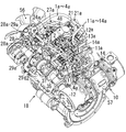
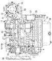
図1、図2に示すように、シリンダヘッド(6)の上部にシリンダヘッドカバー(7)を組み付け、複数の噴射アクチュエータ(1〜4)を、シリンダヘッドカバー(7)の吸気側横側方で前後方向に並べ、各噴射アクチュエータ(1〜4)の電線(1a〜4a)を、シリンダヘッドカバー(7)上でそれぞれ前側の噴射アクチュエータ(1〜3)の電線(1a〜3a)と順に束ねながら、エンジン前部まで導出し、この束ねた電線(1a〜4a)をエンジン前部で吸気側に横向きに折り曲げ、その後に吸気側で後ろ向きに折り曲げ、図3に示すように、その後に吸気側で下向きに折り曲げて、吸気マニホルド(8)の横側を通過させている。 As shown in FIGS. 1 and 2, a cylinder head cover (7) is assembled to the upper part of the cylinder head (6), and a plurality of injection actuators (1 to 4) are moved back and forth on the side of the intake side of the cylinder head cover (7). While arranging the electric wires (1a to 4a) of the injection actuators (1 to 4) in sequence with the electric wires (1a to 3a) of the front injection actuators (1 to 3) on the cylinder head cover (7), Lead to the front of the engine, and the bundled wires (1a to 4a) are bent sideways on the intake side at the front of the engine, then bent backward on the intake side, and then downward on the intake side as shown in FIG. And is passed through the side of the intake manifold (8).
これにより、各噴射アクチュエータ(1〜4)の電線(1a〜4a)がシリンダヘッドカバー(7)上と吸気側で配索され、エンジンの熱を受けにくく、各噴射アクチュエータ(1〜4)の電線(1a〜4a)の熱損傷を防止することができる。 As a result, the electric wires (1a to 4a) of the injection actuators (1 to 4) are routed on the cylinder head cover (7) and the intake side, and are difficult to receive the heat of the engine, and the electric wires of the injection actuators (1 to 4). Thermal damage of (1a to 4a) can be prevented.
図1〜図5に示すように、排気処理装置(10)をエンジン本体(18)に取り付け、排気処理装置(10)に複数の排気センサ(11〜14)を設け、図7に示すように、複数の排気センサ(11〜14)の各電線(11a〜14a)を束ねて排気センサ用コネクタ(15)に接続し、複数の噴射アクチュエータ(1〜4)の電線(1a〜4a)を束ねて噴射アクチュエータ用コネクタ(17)に接続し、エンジン本体用のセンサ(21〜24,28,29)やアクチュエータ(25〜27)の電線(21a〜29a)を束ねてエンジン本体用コネクタ(16)に接続し、排気センサ用コネクタ(15)を噴射アクチュエータ用コネクタ(17)やエンジン本体用コネクタ(16)から分離させている。 As shown in FIGS. 1 to 5, the exhaust treatment device (10) is attached to the engine body (18), and the exhaust treatment device (10) is provided with a plurality of exhaust sensors (11 to 14), as shown in FIG. The electric wires (11a to 14a) of the plurality of exhaust sensors (11 to 14) are bundled and connected to the exhaust sensor connector (15), and the electric wires (1a to 4a) of the plurality of injection actuators (1 to 4) are bundled. Are connected to the injection actuator connector (17), and the engine main body sensors (21 to 24, 28, 29) and the electric wires (21a to 29a) of the actuator (25 to 27) are bundled to connect the engine main body connector (16). The exhaust sensor connector (15) is separated from the injection actuator connector (17) and the engine body connector (16).
これにより、エンジン本体(18)への排気処理装置(10)の取り付け位置が変更され、排気センサ(11〜14)の電線(11a〜14a)を異なる長さのものに交換せざるを得ない場合、排気センサ用コネクタ(15)の交換は必要となるものの、噴射アクチュエータ用コネクタ(17)やエンジン本体用用コネクタ(16)は交換を必要とせず、エンジン本体(18)への排気処理装置(10)の取り付け位置の変更に容易に対応することができる。
なお、図3に示すように、これらのコネクタ(15〜17)は、シリンダブロック(55)の吸気側の壁面にブラケット(19)を介して取り付け、上下に並べ、上から排気センサ用コネクタ(15)、エンジン本体用コネクタ(16)、噴射アクチュエータ用コネクタ(17)としている。
Thereby, the attachment position of the exhaust treatment device (10) to the engine body (18) is changed, and the electric wires (11a to 14a) of the exhaust sensors (11 to 14) must be replaced with ones of different lengths. In this case, the exhaust sensor connector (15) needs to be replaced, but the injection actuator connector (17) and the engine body connector (16) do not need to be replaced. It is possible to easily cope with the change of the attachment position of (10).
In addition, as shown in FIG. 3, these connectors (15-17) are attached to the wall surface of the cylinder block (55) on the intake side via a bracket (19), arranged vertically, and from above the exhaust sensor connector ( 15) an engine body connector (16) and an injection actuator connector (17).
図1〜図4に示すように、噴射アクチュエータ(1〜4)は第1気筒〜第4気筒のものである。噴射アクチュエータ(1〜4)の電線(1a〜4a)は、最後尾の第4気筒の噴射アクチュエータ(4)の電線(4a)にその前の第3気筒の噴射アクチュエータ(3)の電線(3a)が束ねられ、これらにその前の第2気筒の噴射アクチュエータ(2)の電線(2a)が束ねられ、これらに最前部の第1気筒の噴射アクチュエータ(1)の電線(1a)が束ねられる。これらは噴射アクチュエータ用コネクタ(17)に接続される。図7に示すように、この噴射アクチュエータ用コネクタ(17)は制御手段(5)側のコネクタと連結される。制御手段(5)はエンジンECUである。ECUは電子制御ユニットの略称である。 As shown in FIGS. 1 to 4, the injection actuators (1 to 4) are those of the first to fourth cylinders. The electric wires (1a to 4a) of the injection actuators (1 to 4) are connected to the electric wires (4a) of the injection actuator (4) of the last fourth cylinder and the electric wires (3a of the injection actuator (3) of the previous third cylinder. ) Are bundled, and the electric wire (2a) of the injection actuator (2) of the second cylinder in front of them is bundled with them, and the electric wire (1a) of the injection actuator (1) of the foremost first cylinder is bundled with these. . These are connected to the injection actuator connector (17). As shown in FIG. 7, the injection actuator connector (17) is connected to the connector on the control means (5) side. The control means (5) is an engine ECU. ECU is an abbreviation for electronic control unit.
図4に示すように、排気処理装置(10)内では、上流側にDOC(61)が収容され、下流側にDPF(30)が配置されている。
DOCはディーゼル酸化触媒の略称である。
DPFはディーゼルバティキュレートフィルタの略称であり、排気中のPMを捕捉するものである。PMは粒子状物質の略称である。
排気センサ(11〜14)は、DPF入口とDPF出口の排気の差圧を検出する排気差圧センサ(11)、DOC入口の排気温度センサ(12)、DPF入口の排気温度センサ(13)、DPF出口の排気温度センサ(14)であり、これら排気センサ(11〜14)の電線(11a〜14a)は束ねられ、図3、図7に示すように、排気センサ用コネクタ(15)に接続される。この排気センサ用コネクタ(15)は制御手段(5)側のコネクタと連結される。
図4に示すように、排気センサ(11〜14)の電線(11a〜14a)は排気側からヘッドカバー(7)上を吸気側に横断し、吸気側で束ねられ、図3に示すように下向きに折り曲げられ、吸気マニホルド(8)の横側方を通過している。
As shown in FIG. 4, in the exhaust treatment device (10), the DOC (61) is accommodated on the upstream side, and the DPF (30) is disposed on the downstream side.
DOC is an abbreviation for diesel oxidation catalyst.
DPF is an abbreviation for diesel particulate filter and captures PM in exhaust gas. PM is an abbreviation for particulate matter.
The exhaust sensors (11-14) include an exhaust differential pressure sensor (11) for detecting a differential pressure between exhaust at the DPF inlet and the DPF outlet, an exhaust temperature sensor (12) at the DOC inlet, an exhaust temperature sensor (13) at the DPF inlet, An exhaust temperature sensor (14) at the DPF outlet, and the electric wires (11a to 14a) of these exhaust sensors (11 to 14) are bundled and connected to an exhaust sensor connector (15) as shown in FIGS. Is done. This exhaust sensor connector (15) is connected to the connector on the control means (5) side.
As shown in FIG. 4, the wires (11a-14a) of the exhaust sensors (11-14) traverse the head cover (7) from the exhaust side to the intake side, are bundled on the intake side, and face downward as shown in FIG. And passes through the side of the intake manifold (8).
図7に示すように、エンジン本体用のセンサ(21〜24,28,29)は、過給圧センサ(21)、カム角センサ(22)、クランク角センサ(23)、レール圧センサ(24)、水温センサ(28)、油圧スイッチ(29)である。過給圧センサ(21)は過給機(62)から過給パイプ(48)を介して吸気スロットルに供給された過給圧を検出する。カム角センサ(22)はエンジン回転数の半分の回転数で回転するカム軸の角度を検出し、各気筒の上死点が圧縮上死点であるか排気上死点であるか等、各気筒の燃焼行程を判別する。クランク角センサ(23)はクランク角とエンジン回転数を検出する。レール圧センサ(24)はコモンレール(63)のレール圧を検出する。水温センサ(28)はエンジン冷却水の温度を検出する。油圧スイッチ(29)は、オイルギャラリの油圧を検出し、油圧が所定値よりも低い場合にはエンジンを停止させる。 As shown in FIG. 7, the sensors (21 to 24, 28, 29) for the engine main body are a supercharging pressure sensor (21), a cam angle sensor (22), a crank angle sensor (23), a rail pressure sensor (24 ), A water temperature sensor (28), and a hydraulic switch (29). The supercharging pressure sensor (21) detects the supercharging pressure supplied from the supercharger (62) to the intake throttle via the supercharging pipe (48). The cam angle sensor (22) detects the angle of the camshaft rotating at half the engine speed, and whether each cylinder top dead center is compression top dead center or exhaust top dead center, etc. Determine the combustion stroke of the cylinder. The crank angle sensor (23) detects the crank angle and the engine speed. The rail pressure sensor (24) detects the rail pressure of the common rail (63). A water temperature sensor (28) detects the temperature of engine cooling water. The oil pressure switch (29) detects the oil pressure of the oil gallery, and stops the engine when the oil pressure is lower than a predetermined value.
エンジン本体用のアクチュエータ(25〜27)は、スロットルアクチュエータ(25)、EGRバルブアクチュエータ(26)、調量アクチュエータ(27)である。スロットルアクチュエータ(25)はスロットル弁の開度を調節する。EGRバルブアクチュエータ(26)はEGRバルブの開度を調節する。調量アクチュエータ(27)は燃料サプライポンプ(64)からコモンレール(63)への燃料供給量を調量する。 The engine body actuators (25-27) are a throttle actuator (25), an EGR valve actuator (26), and a metering actuator (27). The throttle actuator (25) adjusts the opening of the throttle valve. The EGR valve actuator (26) adjusts the opening degree of the EGR valve. The metering actuator (27) measures the amount of fuel supplied from the fuel supply pump (64) to the common rail (63).
エンジン本体用のセンサ(21〜24,28,29)とアクチュエータ(25〜27)の電線(21a〜29a)は束ねてエンジン本体用コネクタ(16)に接続される。このエンジン本体用コネクタ(16)は、制御手段(5)側のコネクタと連結される。
図3に示すように、エンジン本体用のセンサ(21〜24,28,29)とアクチュエータ(25〜27)の電線(21a〜29a)は吸気側で束ねられ、吸気マニホルド(8)の横側を通過する。
The sensors (21-24, 28, 29) for the engine body and the electric wires (21a-29a) of the actuators (25-27) are bundled and connected to the connector (16) for the engine body. The engine body connector (16) is connected to the connector on the control means (5) side.
As shown in FIG. 3, the sensors (21-24, 28, 29) for the engine body and the wires (21a-29a) of the actuators (25-27) are bundled on the intake side, and the side of the intake manifold (8) Pass through.
図4に示すように、このエンジンは、エンジン本体(18)にDPF(30)を収容した排気処理装置(10)を取り付けた排気処理装置付きエンジンである。
前記の通り、排気処理装置(10)に複数の排気温度センサ(12〜14)を設け、この複数の排気温度センサ(12〜14)にそれぞれ電線(12a〜14a)を接続している。
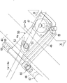
図8に示すように、この電線(12a〜14a)の途中に中継コネクタ(12b〜14b)を配置するとともに、排気処理装置(10)に排気差圧センサ(11)を接続するに当たり、この中継コネクタ(12b〜14b)と排気差圧センサ(11)とを単一のブラケット(31)に一括して取り付け、このブラケット(31)をエンジン本体(18)に取り付けている。
ブラケット(31)はシリンダヘッドカバー(7)の後部の排気側に取り付けている。
As shown in FIG. 4, this engine is an engine with an exhaust treatment device in which an exhaust treatment device (10) containing a DPF (30) is attached to an engine body (18).
As described above, the exhaust treatment device (10) is provided with a plurality of exhaust temperature sensors (12-14), and electric wires (12a-14a) are connected to the plurality of exhaust temperature sensors (12-14), respectively.
As shown in FIG. 8, the relay connectors (12b to 14b) are arranged in the middle of the electric wires (12a to 14a), and the relays are connected to connect the exhaust differential pressure sensor (11) to the exhaust treatment device (10). The connectors (12b to 14b) and the exhaust differential pressure sensor (11) are collectively attached to a single bracket (31), and the bracket (31) is attached to the engine body (18).
The bracket (31) is attached to the exhaust side of the rear part of the cylinder head cover (7).
これにより、エンジン本体(18)に対する排気処理装置(10)の取り付け位置が変更されても、排気処理装置(10)の近くにブラケット(31)の取り付け位置を変更すれば、中継コネクタ(12b〜14b)と排気差圧センサ(11)もブラケット(31)と共に排気処理装置(10)の近くに配置され、エンジン本体(18)への排気処理装置(10)の取り付け位置の変更に容易に対応することができる。 Thereby, even if the attachment position of the exhaust treatment device (10) with respect to the engine body (18) is changed, if the attachment position of the bracket (31) is changed near the exhaust treatment device (10), the relay connector (12b to 12b). 14b) and the exhaust differential pressure sensor (11) are also arranged near the exhaust treatment device (10) together with the bracket (31), and can easily cope with a change in the mounting position of the exhaust treatment device (10) to the engine body (18). can do.
図8に示すように、ブラケット(31)にコネクタ取り付け片(12c〜14c)と遮熱壁(32)とを設け、この遮熱壁(32)の内向き面(33)をコネクタ取り付け片(12c〜14c)に臨ませ、遮熱壁(32)の外向き面(34)を排気マニホルド(35)の上方空間(36)に沿わせた。
これにより、排気マニホルド(35)からその上方空間(36)に浮上する熱気が、遮熱壁(32)で遮られ、中継コネクタ(12b〜14b)を排気マニホルド(35)からその上方空間(36)に浮上する熱気から保護することができる。
As shown in FIG. 8, the bracket (31) is provided with a connector mounting piece (12c to 14c) and a heat shield wall (32), and the inward surface (33) of the heat shield wall (32) is connected to the connector mounting piece ( 12c-14c), the outward surface (34) of the heat shield wall (32) was placed along the upper space (36) of the exhaust manifold (35).
As a result, hot air rising from the exhaust manifold (35) to the upper space (36) is blocked by the heat shield wall (32), and the relay connectors (12b to 14b) are connected to the upper space (36 from the exhaust manifold (35). ) Can be protected from the hot air that emerges.
図8に示すように、遮熱壁(32)の内向き面(33)にクランプ(37・37)を介して排気温度センサ(12〜14)の電線(12a〜14a)を束ねて支持している。
これにより、排気マニホルド(35)からその上方空間(36)に浮上する熱気が、遮熱壁(32)で遮られ、排気温度センサ(12〜14)の電線(12a〜14a)を排気マニホルド(35)からその上方空間(36)に浮上する熱気から保護することができる。
As shown in FIG. 8, the electric wires (12a to 14a) of the exhaust temperature sensors (12 to 14) are bundled and supported via clamps (37 and 37) on the inward surface (33) of the heat shield wall (32). ing.
As a result, hot air rising from the exhaust manifold (35) to the upper space (36) is blocked by the heat shield wall (32), and the electric wires (12a to 14a) of the exhaust temperature sensors (12 to 14) are connected to the exhaust manifold ( It is possible to protect from the hot air that rises from 35) to its upper space (36).
図10に示すように、シリンダヘッド(6)の天井部(40)に弁取付座(41)と弁座(42)とを設け、弁取付座(41)と弁座(42)とは同心の円環状に形成し、弁座(42)の中心部に弁口(43)を設け、弁取付座(41)にダイヤフラム式のブリーザ弁(44)の周縁部を取り付け、弁座(42)にブリーザ弁(44)の中央部の弁面(45)を着座させ、弁口(43)にブリーザ出口通路(46)を連通させ、ブリーザ弁(44)を上方から弁ケース(47)で覆っている。 As shown in FIG. 10, a valve mounting seat (41) and a valve seat (42) are provided on the ceiling (40) of the cylinder head (6), and the valve mounting seat (41) and the valve seat (42) are concentric. The valve seat (42) is provided with a valve opening (43) at the center thereof, the peripheral edge of the diaphragm breather valve (44) is attached to the valve mounting seat (41), and the valve seat (42) The breather valve (44) is seated on the central valve face (45), the breather outlet passage (46) is communicated with the valve port (43), and the breather valve (44) is covered with the valve case (47) from above. ing.
図10に示すように、燃料インジェクタの噴射アクチュエータ(1〜4)の電線(1a〜4a)を弁ケース(47)の上と過給パイプ(48)の下を通過させるに当たり、図9、図10に示すように、シリンダヘッド(6)の天井壁(49)に電線支持板(50)を取り付け、この電線支持板(50)にクランプ取付座(51)を設け、このクランプ取付座(51)に噴射アクチュエータ(1〜4)の電線(1a〜4a)を支持するクランプ(52)を取り付けるとともに、この電線支持板(50)に弁取付座(41)と弁座(42)と弁口(43)とを設け、電線支持板(50)の下面に溝(53)を凹設し、この溝(53)の下開口面をシリンダヘッド(6)の天井壁(49)で塞いで、断面方形状のブリーザ出口通路(46)を形成している。 As shown in FIG. 10, when passing the electric wires (1a to 4a) of the injection actuators (1 to 4) of the fuel injector over the valve case (47) and under the supercharged pipe (48), FIG. As shown in FIG. 10, a wire support plate (50) is attached to the ceiling wall (49) of the cylinder head (6), a clamp mounting seat (51) is provided on the wire support plate (50), and the clamp mounting seat (51 ) Are attached with clamps (52) that support the electric wires (1a-4a) of the injection actuators (1-4), and the electric valve support plate (50) has a valve mounting seat (41), a valve seat (42), and a valve port. (43), a groove (53) is formed in the lower surface of the electric wire support plate (50), and the lower opening surface of the groove (53) is closed by the ceiling wall (49) of the cylinder head (6). A breather outlet passage (46) having a square cross section is formed.
図10に示すように、電線支持板(50)の下面に溝(53)を凹設し、この溝(53)の下開口面をシリンダヘッド(6)の天井壁(49)で塞いで、断面方形状のブリーザ出口通路(46)を形成したので、丸パイプに比べ、短い高さ寸法でもブリーザ出口通路(46)の大きな通路断面積を確保することができ、弁取付座(41)の高さ、ひいては弁ケース(47)の高さを低くすることができる。
このため、過給機付きコモンレール式エンジンに適用し、燃料インジェクタの噴射アクチュエータ(1〜4)の電線(1a〜4a)を弁ケース(47)の上と過給パイプ(48)の下を通過させる場合でも、電線(1a〜4a)が弁ケース(47)の上方を通過する位置を低くすることができ、電線(1a〜4a)を弁ケース(47)と接近した過給パイプ(48)の下方を通過させるのに、電線(1a〜4a)を下方に急角度で折り曲げる必要もなくなり、噴射アクチュエータ(1〜4)の電線(1a〜4a)の配索がブリーザ弁(44)の弁ケース(47)で妨げられることがない。
As shown in FIG. 10, a groove (53) is formed in the lower surface of the electric wire support plate (50), and the lower opening surface of the groove (53) is closed by the ceiling wall (49) of the cylinder head (6). Since the breather outlet passage (46) having a square cross section is formed, a larger passage cross-sectional area of the breather outlet passage (46) can be secured even with a shorter height than the round pipe, and the valve mounting seat (41) can be secured. The height, and hence the height of the valve case (47) can be lowered.
For this reason, it is applied to a common rail engine with a turbocharger, and the electric actuators (1-4) of the fuel injector pass over the valve case (47) and under the supercharged pipe (48). Even in the case where the electric wire (1a to 4a) is passed, the position where the electric wire (1a to 4a) passes above the valve case (47) can be lowered, and the supercharged pipe (48) close to the valve case (47). It is no longer necessary to bend the electric wires (1a to 4a) downward at a steep angle in order to pass through the lower part of the nozzle, and the arrangement of the electric wires (1a to 4a) of the injection actuators (1 to 4) The case (47) is not obstructed.
図10に示すように、ブリーザ出口通路(46)は弁口(43)からブリーザ弁(44)と弁取付座(41)の下方を横断した後、図9に示すように、前方に伸び前端で左右に分岐し、一方の開口(65)をブリーザパイプ(66)を介して過給機(62)のコンプレッサ入口(66)に連通させている。他方の開口(68)はプラグ(69)で塞いでいる。この他方の開口(68)は、過給機(62)のないエンジンに用いる場合には、吸気スロットルに連通させることができる。 As shown in FIG. 10, the breather outlet passage (46) extends forward from the valve port (43) under the breather valve (44) and the valve mounting seat (41) and then extends forward as shown in FIG. And one opening (65) communicates with the compressor inlet (66) of the supercharger (62) through the breather pipe (66). The other opening (68) is closed with a plug (69). This other opening (68) can be communicated with an intake throttle when used in an engine without a supercharger (62).
(1〜4) 噴射アクチュエータ
(1a〜4a) 電線
(5) 制御手段
(6) シリンダヘッド
(7) シリンダヘッドカバー
(10) 排気処理装置
(11) 排気差圧センサ
(12〜14) 排気温度センサ
(11a〜14a) 電線
(15) 排気センサ用コネクタ
(16) エンジン本体用コネクタ
(17) 噴射アクチュエータ用コネクタ
(18) エンジン本体
(21) 過給圧センサ
(22) カム角センサ
(23) クランク角センサ
(24) レール圧センサ
(25) スロットルアクチュエータ
(26) EGRバルブアクチュエータ
(27) 調量アクチュエータ
(28) 水温センサ
(29) 油圧スイッチ
(21a〜29a) 電線
(1-4) Injection actuator
(1a-4a) Electric wire
(5) Control means
(6) Cylinder head
(7) Cylinder head cover
(10) Exhaust treatment equipment
(11) Exhaust differential pressure sensor
(12-14) Exhaust temperature sensor
(11a-14a) Electric wire
(15) Exhaust sensor connector
(16) Engine body connector
(17) Injection actuator connector
(18) Engine body
(21) Boost pressure sensor
(22) Cam angle sensor
(23) Crank angle sensor
(24) Rail pressure sensor
(25) Throttle actuator
(26) EGR valve actuator
(27) Metering actuator
(28) Water temperature sensor
(29) Hydraulic switch
(21a-29a) Electric wire
Claims (3)
噴射アクチュエータ(1〜4)の各電線(1a〜4a)をセンサ(11〜14,21〜24,28,29)の電線(11a〜14a,21a〜24a,28a,29a)とは別に束ね、束ねた噴射アクチュエータ(1〜4)の電線(1a〜4a)からセンサ(11〜14,21〜24,28,29)の電線(11a〜14a,21a〜24a,28a,29a)を分離させた、ことを特徴とするコモンレール式エンジン。 Electric wires (1a to 4a) are connected to the injection actuators (1 to 4) of a plurality of fuel injectors, respectively, and electricity is supplied from the control means (5) to the injection actuators (1 to 4) via the electric wires (1a to 4a). In a common rail engine that transmits a signal, controls the operation of each injection actuator (1 to 4) with this electric signal, and injects fuel into each cylinder from each fuel injector,
Bundle each wire (1a-4a) of the injection actuator (1-4) separately from the wires (11a-14a, 21a-24a, 28a, 29a) of the sensors (11-14, 21-24, 28, 29), The wires (11a-14a, 21a-24a, 28a, 29a) of the sensors (11-14, 21-24, 28, 29) were separated from the wires (1a-4a) of the bundled injection actuators (1-4). This is a common rail engine.
シリンダヘッド(6)の上部にシリンダヘッドカバー(7)を組み付け、複数の噴射アクチュエータ(1〜4)を、シリンダヘッドカバー(7)の吸気側横側方で前後方向に並べ、各噴射アクチュエータ(1〜4)の電線(1a〜4a)を、シリンダヘッドカバー(7)上でそれぞれ前側の噴射アクチュエータ(1〜3)の電線(1a〜3a)と順に束ねながら、エンジン前部まで導出し、この束ねた電線(1a〜4a)をエンジン前部で吸気側に横向きに折り曲げ、その後に吸気側で後ろ向きに折り曲げ、その後に吸気側で下向きに折り曲げて、吸気マニホルド(8)の横側を通過させたことを特徴とするコモンレール式エンジン。 In the common rail engine according to claim 1,
A cylinder head cover (7) is assembled to the upper part of the cylinder head (6), and a plurality of injection actuators (1 to 4) are arranged in the front-rear direction on the intake side lateral side of the cylinder head cover (7). 4) The electric wires (1a to 4a) of 4) were led out to the front of the engine while being bundled in order with the electric wires (1a to 3a) of the front injection actuators (1 to 3) on the cylinder head cover (7). The electric wires (1a to 4a) were bent sideways on the intake side at the front of the engine, then bent backward on the intake side, then bent downward on the intake side, and passed through the side of the intake manifold (8). A common rail engine characterized by
排気処理装置(10)をエンジン本体(18)に取り付け、排気処理装置(10)に複数の排気センサ(11〜14)を設け、複数の排気センサ(11〜14)の各電線(11a〜14a)を束ねて排気センサ用コネクタ(15)に接続し、複数の噴射アクチュエータ(1〜4)の電線(1a〜4a)を束ねて噴射アクチュエータ用コネクタ(17)に接続し、エンジン本体用のセンサ(21〜24,28,29)やアクチュエータ(25〜27)の電線(21a〜29a)を束ねてエンジン本体用コネクタ(16)に接続し、排気センサ用コネクタ(15)を噴射アクチュエータ用コネクタ(17)やエンジン本体用コネクタ(16)から分離させた、ことを特徴とするコモンレール式エンジン。 In the common rail type engine according to claim 1 or 2,
The exhaust treatment device (10) is attached to the engine body (18), the exhaust treatment device (10) is provided with a plurality of exhaust sensors (11-14), and the electric wires (11a-14a) of the plurality of exhaust sensors (11-14) are provided. ) Are bundled and connected to the exhaust sensor connector (15), and the wires (1a to 4a) of the plurality of injection actuators (1 to 4) are bundled and connected to the injection actuator connector (17). (21-24, 28, 29) and the wires (21a-29a) of the actuators (25-27) are bundled and connected to the engine body connector (16), and the exhaust sensor connector (15) is connected to the injection actuator connector (15). 17) A common rail engine separated from the engine main body connector (16).
Priority Applications (1)
| Application Number | Priority Date | Filing Date | Title |
|---|---|---|---|
| JP2011216725A JP2013076366A (en) | 2011-09-30 | 2011-09-30 | Common rail engine |
Applications Claiming Priority (1)
| Application Number | Priority Date | Filing Date | Title |
|---|---|---|---|
| JP2011216725A JP2013076366A (en) | 2011-09-30 | 2011-09-30 | Common rail engine |
Publications (1)
| Publication Number | Publication Date |
|---|---|
| JP2013076366A true JP2013076366A (en) | 2013-04-25 |
Family
ID=48480001
Family Applications (1)
| Application Number | Title | Priority Date | Filing Date |
|---|---|---|---|
| JP2011216725A Pending JP2013076366A (en) | 2011-09-30 | 2011-09-30 | Common rail engine |
Country Status (1)
| Country | Link |
|---|---|
| JP (1) | JP2013076366A (en) |
Cited By (1)
| Publication number | Priority date | Publication date | Assignee | Title |
|---|---|---|---|---|
| JP2015008581A (en) * | 2013-06-25 | 2015-01-15 | 株式会社Ihiシバウラ | Diesel engine harness mounting structure and diesel engine |
Citations (8)
| Publication number | Priority date | Publication date | Assignee | Title |
|---|---|---|---|---|
| JPS58167244A (en) * | 1982-03-29 | 1983-10-03 | Nissan Motor Co Ltd | Laying system for wire harness |
| JPH0649717U (en) * | 1992-12-08 | 1994-07-08 | 日産ディーゼル工業株式会社 | Filter regeneration device for particulate trap |
| JPH11343861A (en) * | 1998-05-29 | 1999-12-14 | Toyota Motor Corp | Engine control device |
| JP2001315592A (en) * | 2000-05-10 | 2001-11-13 | Auto Network Gijutsu Kenkyusho:Kk | Harness structure of engine related parts |
| JP2006316757A (en) * | 2005-05-16 | 2006-11-24 | Isuzu Motors Ltd | Exhaust gas purification method and exhaust gas purification system |
| US20080098727A1 (en) * | 2006-10-31 | 2008-05-01 | Caterpillar Inc. | Selective oxidation catalyst injection based on temperature |
| JP2010043574A (en) * | 2008-08-11 | 2010-02-25 | Hitachi Constr Mach Co Ltd | Exhaust emission control device |
| JP2011047773A (en) * | 2009-08-26 | 2011-03-10 | Yanmar Co Ltd | Engine and method of inspecting the same |
-
2011
- 2011-09-30 JP JP2011216725A patent/JP2013076366A/en active Pending
Patent Citations (8)
| Publication number | Priority date | Publication date | Assignee | Title |
|---|---|---|---|---|
| JPS58167244A (en) * | 1982-03-29 | 1983-10-03 | Nissan Motor Co Ltd | Laying system for wire harness |
| JPH0649717U (en) * | 1992-12-08 | 1994-07-08 | 日産ディーゼル工業株式会社 | Filter regeneration device for particulate trap |
| JPH11343861A (en) * | 1998-05-29 | 1999-12-14 | Toyota Motor Corp | Engine control device |
| JP2001315592A (en) * | 2000-05-10 | 2001-11-13 | Auto Network Gijutsu Kenkyusho:Kk | Harness structure of engine related parts |
| JP2006316757A (en) * | 2005-05-16 | 2006-11-24 | Isuzu Motors Ltd | Exhaust gas purification method and exhaust gas purification system |
| US20080098727A1 (en) * | 2006-10-31 | 2008-05-01 | Caterpillar Inc. | Selective oxidation catalyst injection based on temperature |
| JP2010043574A (en) * | 2008-08-11 | 2010-02-25 | Hitachi Constr Mach Co Ltd | Exhaust emission control device |
| JP2011047773A (en) * | 2009-08-26 | 2011-03-10 | Yanmar Co Ltd | Engine and method of inspecting the same |
Cited By (1)
| Publication number | Priority date | Publication date | Assignee | Title |
|---|---|---|---|---|
| JP2015008581A (en) * | 2013-06-25 | 2015-01-15 | 株式会社Ihiシバウラ | Diesel engine harness mounting structure and diesel engine |
Similar Documents
| Publication | Publication Date | Title |
|---|---|---|
| JP5798515B2 (en) | Vertical in-line multi-cylinder engine with exhaust treatment system | |
| US8534239B2 (en) | Multi-cylinder diesel engine | |
| JP4429359B2 (en) | Device for controlling exhaust pressure pulsation in an internal combustion engine | |
| ITTO20010786A1 (en) | SELF-PRIMING METHOD OF THE REGENERATION OF A PARTICULATE FILTER FOR A DIRECT INJECTION DIESEL ENGINE PROVIDED WITH AN INI PLANT | |
| EP2489852A1 (en) | Control device for internal combustion engine equipped with supercharger | |
| EP2848798B1 (en) | An exhaust gas recirculation cooler mount | |
| JP2009287476A (en) | Intake air control device for general purpose engine | |
| JP5687990B2 (en) | Engine with exhaust treatment device | |
| JP2011080396A (en) | Egr device | |
| CN109790777B (en) | Turbocharged engine | |
| EP2825755B1 (en) | Method for enriching exhaust gases with unburnt hydrocarbon | |
| JP6047974B2 (en) | Gas sensor protective cover structure | |
| JP2013076366A (en) | Common rail engine | |
| EP2527628B1 (en) | Control device of an internal combustion engine | |
| JP2013076368A (en) | Engine with breather device | |
| JP2008255941A (en) | Work vehicle workload control device | |
| EP2957737B1 (en) | Engine exhaust-gas purification device | |
| JP5707289B2 (en) | Engine with exhaust treatment device | |
| EP1607595B1 (en) | An exhaust system for a turbocharged diesel engine | |
| JP6724997B2 (en) | Intake passage structure for turbocharged engine | |
| JP4206781B2 (en) | Exhaust manifold structure of engine with exhaust supercharger | |
| JP2005273610A (en) | Turbocharged engine | |
| JP6209989B2 (en) | Turbocharged engine | |
| JP6232346B2 (en) | engine | |
| JP6032802B2 (en) | EGR device |
Legal Events
| Date | Code | Title | Description |
|---|---|---|---|
| A621 | Written request for application examination |
Free format text: JAPANESE INTERMEDIATE CODE: A621 Effective date: 20130926 |
|
| A131 | Notification of reasons for refusal |
Free format text: JAPANESE INTERMEDIATE CODE: A131 Effective date: 20140826 |
|
| A977 | Report on retrieval |
Free format text: JAPANESE INTERMEDIATE CODE: A971007 Effective date: 20140828 |
|
| A02 | Decision of refusal |
Free format text: JAPANESE INTERMEDIATE CODE: A02 Effective date: 20150217 |