JP2013105751A - 接触器の中に組込可能な、交流電流が供給される電気回路を保護するための装置 - Google Patents
接触器の中に組込可能な、交流電流が供給される電気回路を保護するための装置 Download PDFInfo
- Publication number
- JP2013105751A JP2013105751A JP2012266711A JP2012266711A JP2013105751A JP 2013105751 A JP2013105751 A JP 2013105751A JP 2012266711 A JP2012266711 A JP 2012266711A JP 2012266711 A JP2012266711 A JP 2012266711A JP 2013105751 A JP2013105751 A JP 2013105751A
- Authority
- JP
- Japan
- Prior art keywords
- housing
- contactor
- electrical
- fuse
- switching element
- Prior art date
- Legal status (The legal status is an assumption and is not a legal conclusion. Google has not performed a legal analysis and makes no representation as to the accuracy of the status listed.)
- Granted
Links
Images


Classifications
-
- H—ELECTRICITY
- H01—ELECTRIC ELEMENTS
- H01H—ELECTRIC SWITCHES; RELAYS; SELECTORS; EMERGENCY PROTECTIVE DEVICES
- H01H9/00—Details of switching devices, not covered by groups H01H1/00 - H01H7/00
- H01H9/10—Adaptation for built-in fuses
-
- H—ELECTRICITY
- H01—ELECTRIC ELEMENTS
- H01H—ELECTRIC SWITCHES; RELAYS; SELECTORS; EMERGENCY PROTECTIVE DEVICES
- H01H1/00—Contacts
- H01H1/12—Contacts characterised by the manner in which co-operating contacts engage
- H01H1/14—Contacts characterised by the manner in which co-operating contacts engage by abutting
- H01H1/20—Bridging contacts
- H01H1/2008—Facilitate mounting or replacing contact bridge and pressure spring on carrier
-
- H—ELECTRICITY
- H01—ELECTRIC ELEMENTS
- H01H—ELECTRIC SWITCHES; RELAYS; SELECTORS; EMERGENCY PROTECTIVE DEVICES
- H01H50/00—Details of electromagnetic relays
- H01H50/54—Contact arrangements
- H01H50/546—Contact arrangements for contactors having bridging contacts
-
- H—ELECTRICITY
- H01—ELECTRIC ELEMENTS
- H01H—ELECTRIC SWITCHES; RELAYS; SELECTORS; EMERGENCY PROTECTIVE DEVICES
- H01H85/00—Protective devices in which the current flows through a part of fusible material and this current is interrupted by displacement of the fusible material when this current becomes excessive
- H01H85/0078—Security-related arrangements
- H01H85/0082—Security-related arrangements preventing explosion of the cartridge
- H01H85/0086—Security-related arrangements preventing explosion of the cartridge use of a flexible body, e.g. inside the casing
-
- H—ELECTRICITY
- H01—ELECTRIC ELEMENTS
- H01H—ELECTRIC SWITCHES; RELAYS; SELECTORS; EMERGENCY PROTECTIVE DEVICES
- H01H85/00—Protective devices in which the current flows through a part of fusible material and this current is interrupted by displacement of the fusible material when this current becomes excessive
- H01H85/54—Protective devices wherein the fuse is carried, held, or retained by an intermediate or auxiliary part removable from the base, or used as sectionalisers
-
- H—ELECTRICITY
- H01—ELECTRIC ELEMENTS
- H01H—ELECTRIC SWITCHES; RELAYS; SELECTORS; EMERGENCY PROTECTIVE DEVICES
- H01H85/00—Protective devices in which the current flows through a part of fusible material and this current is interrupted by displacement of the fusible material when this current becomes excessive
- H01H85/54—Protective devices wherein the fuse is carried, held, or retained by an intermediate or auxiliary part removable from the base, or used as sectionalisers
- H01H85/547—Protective devices wherein the fuse is carried, held, or retained by an intermediate or auxiliary part removable from the base, or used as sectionalisers with sliding fuse carrier
-
- H—ELECTRICITY
- H01—ELECTRIC ELEMENTS
- H01H—ELECTRIC SWITCHES; RELAYS; SELECTORS; EMERGENCY PROTECTIVE DEVICES
- H01H85/00—Protective devices in which the current flows through a part of fusible material and this current is interrupted by displacement of the fusible material when this current becomes excessive
- H01H85/54—Protective devices wherein the fuse is carried, held, or retained by an intermediate or auxiliary part removable from the base, or used as sectionalisers
- H01H85/60—Protective devices wherein the fuse is carried, held, or retained by an intermediate or auxiliary part removable from the base, or used as sectionalisers the intermediate or auxiliary part having contacts at opposite ends for co-operation with the base
-
- H—ELECTRICITY
- H01—ELECTRIC ELEMENTS
- H01H—ELECTRIC SWITCHES; RELAYS; SELECTORS; EMERGENCY PROTECTIVE DEVICES
- H01H9/00—Details of switching devices, not covered by groups H01H1/00 - H01H7/00
- H01H9/10—Adaptation for built-in fuses
- H01H9/102—Fuses mounted on or constituting the movable contact parts of the switch
-
- H—ELECTRICITY
- H01—ELECTRIC ELEMENTS
- H01H—ELECTRIC SWITCHES; RELAYS; SELECTORS; EMERGENCY PROTECTIVE DEVICES
- H01H1/00—Contacts
- H01H1/12—Contacts characterised by the manner in which co-operating contacts engage
- H01H1/14—Contacts characterised by the manner in which co-operating contacts engage by abutting
- H01H1/22—Contacts characterised by the manner in which co-operating contacts engage by abutting with rigid pivoted member carrying the moving contact
- H01H1/221—Contacts characterised by the manner in which co-operating contacts engage by abutting with rigid pivoted member carrying the moving contact and a contact pressure spring acting between the pivoted member and a supporting member
- H01H2001/223—Contacts characterised by the manner in which co-operating contacts engage by abutting with rigid pivoted member carrying the moving contact and a contact pressure spring acting between the pivoted member and a supporting member using a torsion spring
Landscapes
- Physics & Mathematics (AREA)
- Electromagnetism (AREA)
- Engineering & Computer Science (AREA)
- Computer Security & Cryptography (AREA)
- Fuses (AREA)
- Switch Cases, Indication, And Locking (AREA)
- Emergency Protection Circuit Devices (AREA)
- Details Of Connecting Devices For Male And Female Coupling (AREA)
Abstract
【解決手段】ハウジング(10)と、ハウジング(10)内に配置されたヒューズ素子(16)とを含む、交流電流が供給される電気回路を保護するための装置。ハウジング(10)は、互いに対して可動な第1の部分(11)及び第2の部分(12)と、第1の部分(11)が前記第2の部分に当接して支えられるようにさせて、ハウジング(10)が閉鎖状態にセットされるようにさせるのに適した弾性手段(6)とを含む。
【選択図】図3
Description
a)ハウジングの開放、
b)ハウジングの外部への電気アークの膨張、
c)ハウジングの閉鎖、
d)ハウジングが閉鎖されたときの、電気アークの遮断、及び
e)電気アークが再形成された場合の、ステップa)からd)までの反復
を含む。
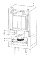
2:スイッチング素子
3:電気結合端子
5:電磁石
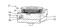
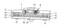
6:弾性手段(ばね)
10:ハウジング
11:第1の部分
12:第2の部分
13:機械的結合要素
14:溝
15:接続端子
16:ヒューズ素子
17:接続スタッド
18:ろう付け接合部
51:固定部
52:可動部
T:トンネル
t1、t2:時間
V:電圧
I:電流
Claims (11)
- ハウジング(10)と、前記ハウジング(10)内に配置されたヒューズ素子(16)とを備えた、交流電流が供給される電気回路を保護するための装置であって、前記ハウジング(10)は、互いに対して可動な第1の部分(11)及び第2の部分(12)と、前記第1の部分(11)が前記第2の部分に当接して支えられるようにさせて、前記ハウジング(10)が閉鎖状態にセットされるようにさせるのに適した弾性手段(6)とを備えることを特徴とする、装置。
- 前記弾性手段(6)は、前記ハウジング(10)内の圧力が閾値より高いときに前記ハウジング(10)の前記第1の部分(11)と前記第2の部分(12)とを分離させることができるように設けられることを特徴とする、請求項1に記載の装置。
- 前記ヒューズ素子(16)の各々の側に結合した、前記第2の部分(12)上に固定された少なくとも2つの接続端子(15)を備え、前記第1の部分及び前記第2の部分は、前記2つの接続端子(15)によって定められる方向に従って互いに分離することになるように設けられることを特徴とする、請求項1〜請求項2のいずれかに記載の装置。
- 前記ハウジング(10)の前記第1の部分(11)及び前記第2の部分(12)は、炭化しない面を有する材料をその内面上に含むことを特徴とする、請求項1〜請求項3のいずれかに記載の装置。
- 前記ヒューズ素子(16)は、前記2つの接続端子(15)間に設けられた少なくとも1つのろう付け接合部(18)を備えることを特徴とする、請求項3〜請求項4のいずれかに記載の装置。
- 交流電流が供給される電気回路を開路又は閉路するのに適したスイッチング素子(2)と、前記スイッチング素子(2)が前記電気回路を開路又は閉路することを制御するのに適した制御手段とを備えた電気接触器(1)であって、前記スイッチング素子(2)は、請求項1〜請求項5のいずれかに記載の保護装置を含むことを特徴とする、電気接触器(1)。
- 前記電気接触器は、前記電気回路に接続された電気結合端子(3)を備え、前記スイッチング素子は、前記保護装置の前記接続端子(15)にそれぞれ接続された少なくとも2つの接続スタッド(17)を備え、前記制御手段は、前記接続スタッド(17)が前記電気結合端子(3)から切り離される前記電気回路開位置と前記接続スタッド(17)が前記電気結合端子(3)に結合する前記電気回路閉位置との間で前記スイッチング素子(2)を移動させる、前記スイッチング素子(2)に結合された移動手段(5)を備えることを特徴とする、請求項6に記載の電気接触器(1)。
- 前記スイッチング素子(2)を前記電気回路閉位置に持ってくるように前記移動手段(5)に結合された弾性接触手段を備え、前記弾性接触手段は、前記保護装置の前記弾性手段(6)を含むことを特徴とする、請求項7に記載の電気接触器(1)。
- 前記接触器(1)は、電力接触器であることを特徴とする、請求項6〜請求項8のいずれかに記載の電気接触器(1)
- 短絡に関連した電流の増大によって引き起こされるハウジング(10)内のヒューズ素子(16)の融解に続く電気アークの生成を含む、交流電流が供給される電気回路を保護するための方法であって、
a)前記ハウジング(10)の開放ステップ、
b)前記ハウジング(10)の外部への前記電気アークの膨張ステップ、
c)前記ハウジング(10)の閉鎖ステップ、
d)前記ハウジング(10)が閉鎖されたときの、前記電気アークの遮断ステップ、及び
e)前記電気アークが再形成された場合の、ステップa)からd)までの反復ステップ
を含むことを特徴とする、方法。 - 前記ハウジング(10)は、前記ハウジング(10)内の圧力が閾値より高いときには開放され、前記圧力が前記閾値より低いときには閉鎖され、前記ハウジング(10)内の前記圧力は、交流電流の絶対値が減少したときに降下することを特徴とする、請求項10に記載の方法。
Applications Claiming Priority (2)
| Application Number | Priority Date | Filing Date | Title |
|---|---|---|---|
| FR1160451 | 2011-11-16 | ||
| FR1160451A FR2982705B1 (fr) | 2011-11-16 | 2011-11-16 | Dispositif de protection d'un circuit electrique alimente par un courant alternatif integrable dans un contacteur. |
Publications (2)
| Publication Number | Publication Date |
|---|---|
| JP2013105751A true JP2013105751A (ja) | 2013-05-30 |
| JP6247002B2 JP6247002B2 (ja) | 2017-12-13 |
Family
ID=48145242
Family Applications (1)
| Application Number | Title | Priority Date | Filing Date |
|---|---|---|---|
| JP2012266711A Expired - Fee Related JP6247002B2 (ja) | 2011-11-16 | 2012-11-16 | 接触器の中に組込可能な、交流電流が供給される電気回路を保護するための装置 |
Country Status (6)
| Country | Link |
|---|---|
| US (1) | US9773625B2 (ja) |
| JP (1) | JP6247002B2 (ja) |
| CN (1) | CN103117198B (ja) |
| BR (1) | BR102012028980B1 (ja) |
| DE (1) | DE102012021668A1 (ja) |
| FR (1) | FR2982705B1 (ja) |
Cited By (1)
| Publication number | Priority date | Publication date | Assignee | Title |
|---|---|---|---|---|
| JP2016134383A (ja) * | 2015-01-15 | 2016-07-25 | フオルクスヴアーゲン アクチエンゲゼルシヤフトVolkswagen AG | 高電圧搭載電源用の切換及び保護装置 |
Families Citing this family (3)
| Publication number | Priority date | Publication date | Assignee | Title |
|---|---|---|---|---|
| JP2563070Y2 (ja) | 1991-11-27 | 1998-02-18 | 三菱電機株式会社 | レーダ装置 |
| JP3197084B2 (ja) | 1992-12-03 | 2001-08-13 | 株式会社東芝 | レーダ装置 |
| WO2017036380A1 (en) * | 2015-08-31 | 2017-03-09 | Byd Company Limited | Relay |
Citations (7)
| Publication number | Priority date | Publication date | Assignee | Title |
|---|---|---|---|---|
| JPS4426998Y1 (ja) * | 1967-03-29 | 1969-11-12 | ||
| JPS478941U (ja) * | 1971-02-24 | 1972-10-03 | ||
| JPS50141151U (ja) * | 1974-05-10 | 1975-11-20 | ||
| JPS5665554U (ja) * | 1979-10-25 | 1981-06-01 | ||
| JPS61158060U (ja) * | 1985-03-25 | 1986-09-30 | ||
| JPH04322028A (ja) * | 1990-11-05 | 1992-11-12 | Wickmann Werke Gmbh | ミニチュアヒューズ |
| JP2010277802A (ja) * | 2009-05-28 | 2010-12-09 | Denso Corp | 電磁継電器 |
Family Cites Families (16)
| Publication number | Priority date | Publication date | Assignee | Title |
|---|---|---|---|---|
| US2186813A (en) * | 1936-06-29 | 1940-01-09 | Frank Adam Electric Co | Circuit interrupting and protecting device |
| US2249014A (en) * | 1936-09-29 | 1941-07-15 | Westinghouse Electric & Mfg Co | Distribution cutout |
| US2423227A (en) * | 1943-12-18 | 1947-07-01 | Cole Ind Inc | Combined fuse and electric switch |
| US2834855A (en) * | 1956-04-18 | 1958-05-13 | Gen Electric | Load break device |
| FR1360265A (fr) * | 1963-03-26 | 1964-05-08 | Coupe-circuit à serrage magnétique | |
| US3599135A (en) * | 1970-01-12 | 1971-08-10 | Ite Imperial Corp | Circuit protection arrangement including coordinated operation of a circuit breaker and a current limiting fuse |
| US5287079A (en) * | 1992-11-09 | 1994-02-15 | Cooper Industries, Inc. | Sub-miniature plastic fuse |
| AU678623B2 (en) * | 1993-12-13 | 1997-06-05 | Eaton Corporation | Arc-quenching filler for high voltage current limiting fuses and circuit interrupters |
| EP0780860B1 (fr) * | 1995-12-20 | 2003-05-07 | Legrand | Interrupteur auxiliaire pour coupe-circuit, et coupe-circuit correspondant |
| IT1286436B1 (it) * | 1996-12-04 | 1998-07-08 | Abb Elettrocondutture Spa | Porta-fusibile sezionatore per quadro elettrico |
| US5973418A (en) * | 1998-05-05 | 1999-10-26 | Cooper Technologies Company | Pull-out high current switch |
| US6542063B2 (en) * | 2001-01-31 | 2003-04-01 | Nippon Seisne Cable, Ltd. | Electric fuse |
| US6762670B1 (en) * | 2003-04-10 | 2004-07-13 | Chun-Chang Yen | Fuse apparatus with explosion-proof structure |
| DE10334069A1 (de) * | 2003-07-25 | 2005-03-03 | Siemens Ag | Sicherungsbehaftetes Schaltschutzgerät |
| WO2006031696A1 (en) * | 2004-09-13 | 2006-03-23 | Cooper Technologies Company | Fusible switching disconnect modules and devices |
| US7458845B2 (en) * | 2006-06-15 | 2008-12-02 | Sound Sources Technolog, Inc | Terminal assembly for selectively coupling loads in parallel and in series |
-
2011
- 2011-11-16 FR FR1160451A patent/FR2982705B1/fr active Active
-
2012
- 2012-11-07 DE DE102012021668A patent/DE102012021668A1/de not_active Withdrawn
- 2012-11-07 US US13/671,206 patent/US9773625B2/en active Active
- 2012-11-13 BR BR102012028980-6A patent/BR102012028980B1/pt not_active IP Right Cessation
- 2012-11-16 JP JP2012266711A patent/JP6247002B2/ja not_active Expired - Fee Related
- 2012-11-16 CN CN201210466497.7A patent/CN103117198B/zh active Active
Patent Citations (7)
| Publication number | Priority date | Publication date | Assignee | Title |
|---|---|---|---|---|
| JPS4426998Y1 (ja) * | 1967-03-29 | 1969-11-12 | ||
| JPS478941U (ja) * | 1971-02-24 | 1972-10-03 | ||
| JPS50141151U (ja) * | 1974-05-10 | 1975-11-20 | ||
| JPS5665554U (ja) * | 1979-10-25 | 1981-06-01 | ||
| JPS61158060U (ja) * | 1985-03-25 | 1986-09-30 | ||
| JPH04322028A (ja) * | 1990-11-05 | 1992-11-12 | Wickmann Werke Gmbh | ミニチュアヒューズ |
| JP2010277802A (ja) * | 2009-05-28 | 2010-12-09 | Denso Corp | 電磁継電器 |
Cited By (3)
| Publication number | Priority date | Publication date | Assignee | Title |
|---|---|---|---|---|
| JP2016134383A (ja) * | 2015-01-15 | 2016-07-25 | フオルクスヴアーゲン アクチエンゲゼルシヤフトVolkswagen AG | 高電圧搭載電源用の切換及び保護装置 |
| KR101798730B1 (ko) * | 2015-01-15 | 2017-12-12 | 폭스바겐 악티엔 게젤샤프트 | 고전압 전기 시스템용 스위칭 및 보호 장치 |
| US10276314B2 (en) | 2015-01-15 | 2019-04-30 | Volkswagen Ag | Switching and protection device for high-voltage wiring system |
Also Published As
| Publication number | Publication date |
|---|---|
| US20130127583A1 (en) | 2013-05-23 |
| CN103117198A (zh) | 2013-05-22 |
| JP6247002B2 (ja) | 2017-12-13 |
| US9773625B2 (en) | 2017-09-26 |
| CN103117198B (zh) | 2017-05-10 |
| FR2982705B1 (fr) | 2013-11-15 |
| BR102012028980A2 (pt) | 2015-11-03 |
| BR102012028980B1 (pt) | 2020-11-17 |
| BR102012028980A8 (pt) | 2015-12-08 |
| FR2982705A1 (fr) | 2013-05-17 |
| DE102012021668A1 (de) | 2013-05-16 |
Similar Documents
| Publication | Publication Date | Title |
|---|---|---|
| JP6165278B2 (ja) | 高電圧搭載電源用の切換及び保護装置 | |
| CN203839326U (zh) | 一种高压直流温度保险丝 | |
| CN105337169B (zh) | 一种组合式电涌保护装置 | |
| JP6357221B2 (ja) | 保護デバイス | |
| JPWO2015002187A1 (ja) | 保護デバイス | |
| US6590490B2 (en) | Time delay fuse | |
| SK2122002A3 (en) | Current limiting high voltage fuse | |
| CN103748651A (zh) | 熔断器 | |
| JP6247002B2 (ja) | 接触器の中に組込可能な、交流電流が供給される電気回路を保護するための装置 | |
| US20080186643A1 (en) | Voltage surge protection device with a movable contact comprising selective disconnection means against short-circuits | |
| EP3869531B1 (en) | High-voltage fusing apparatus | |
| KR100560058B1 (ko) | 보호소자 | |
| CN117334542B (zh) | 一种分隔腔体带隔离灭弧的熔断器 | |
| JP4708310B2 (ja) | 回路遮断装置 | |
| JP2009032567A (ja) | ヒューズ | |
| JP2015116577A (ja) | クラッドメタルと金属部品の接合方法及びその接合方法を用いた熱動式引き外し装置の製造方法並びに回路遮断器 | |
| US6538551B2 (en) | Heat concentrating barrel for wire heater in dual element fuses | |
| CN110383413A (zh) | 用于低压应用的熔断保险装置 | |
| JP7416505B1 (ja) | 保護素子 | |
| CN201877382U (zh) | 限流熔断器 | |
| CN222705433U (zh) | 一种用电设备及其抗大电流浪涌与灭弧性能温度保险丝 | |
| CN223462190U (zh) | 一种温度管理系统及其温度熔断器 | |
| JP4697462B2 (ja) | 回路遮断装置 | |
| CN220934004U (zh) | 用于智能熔断器的灭弧结构及具有其的智能熔断器 | |
| JP2020068196A (ja) | ヒューズ抵抗組立体及びヒューズ抵抗組立体の製造方法 |
Legal Events
| Date | Code | Title | Description |
|---|---|---|---|
| A621 | Written request for application examination |
Free format text: JAPANESE INTERMEDIATE CODE: A621 Effective date: 20151019 |
|
| A977 | Report on retrieval |
Free format text: JAPANESE INTERMEDIATE CODE: A971007 Effective date: 20160801 |
|
| A131 | Notification of reasons for refusal |
Free format text: JAPANESE INTERMEDIATE CODE: A131 Effective date: 20160803 |
|
| A601 | Written request for extension of time |
Free format text: JAPANESE INTERMEDIATE CODE: A601 Effective date: 20161101 |
|
| A521 | Request for written amendment filed |
Free format text: JAPANESE INTERMEDIATE CODE: A523 Effective date: 20170104 |
|
| A02 | Decision of refusal |
Free format text: JAPANESE INTERMEDIATE CODE: A02 Effective date: 20170419 |
|
| A521 | Request for written amendment filed |
Free format text: JAPANESE INTERMEDIATE CODE: A523 Effective date: 20170821 |
|
| A911 | Transfer to examiner for re-examination before appeal (zenchi) |
Free format text: JAPANESE INTERMEDIATE CODE: A911 Effective date: 20171016 |
|
| TRDD | Decision of grant or rejection written | ||
| A01 | Written decision to grant a patent or to grant a registration (utility model) |
Free format text: JAPANESE INTERMEDIATE CODE: A01 Effective date: 20171101 |
|
| A61 | First payment of annual fees (during grant procedure) |
Free format text: JAPANESE INTERMEDIATE CODE: A61 Effective date: 20171116 |
|
| R150 | Certificate of patent or registration of utility model |
Ref document number: 6247002 Country of ref document: JP Free format text: JAPANESE INTERMEDIATE CODE: R150 |
|
| R250 | Receipt of annual fees |
Free format text: JAPANESE INTERMEDIATE CODE: R250 |
|
| S111 | Request for change of ownership or part of ownership |
Free format text: JAPANESE INTERMEDIATE CODE: R313113 |
|
| S531 | Written request for registration of change of domicile |
Free format text: JAPANESE INTERMEDIATE CODE: R313531 |
|
| S533 | Written request for registration of change of name |
Free format text: JAPANESE INTERMEDIATE CODE: R313533 |
|
| R350 | Written notification of registration of transfer |
Free format text: JAPANESE INTERMEDIATE CODE: R350 |
|
| R250 | Receipt of annual fees |
Free format text: JAPANESE INTERMEDIATE CODE: R250 |
|
| LAPS | Cancellation because of no payment of annual fees |