JP2013106945A - Folding chair - Google Patents
Folding chair Download PDFInfo
- Publication number
- JP2013106945A JP2013106945A JP2012241169A JP2012241169A JP2013106945A JP 2013106945 A JP2013106945 A JP 2013106945A JP 2012241169 A JP2012241169 A JP 2012241169A JP 2012241169 A JP2012241169 A JP 2012241169A JP 2013106945 A JP2013106945 A JP 2013106945A
- Authority
- JP
- Japan
- Prior art keywords
- frame
- folding chair
- support shaft
- seat plate
- folding
- Prior art date
- Legal status (The legal status is an assumption and is not a legal conclusion. Google has not performed a legal analysis and makes no representation as to the accuracy of the status listed.)
- Granted
Links
Images

Landscapes
- Special Chairs (AREA)
Abstract
【課題】簡易な構造であって平坦状に折畳み可能な折畳み椅子、及び狭い場所に収納し易く、且つ取り出し易い折畳み椅子を提供する。
【解決手段】折畳み椅子30は、左右一対の第1のフレーム37と、第1のフレーム37に第1の支軸34を介して回動可能に連結された左右一対の第2のフレーム36と、第2のフレーム36に前方が回動可能に連結され、第1のフレーム37に後方が第2の支軸46を介して回動可能に連結された座板31と、を具備し、第1のフレーム37には、第1の支軸34又は第2の支軸46が係合する係合部45が形成され、この係合部45は、第1フレーム37の軸線に沿って形成されており、第1のフレーム37に対する第2のフレーム36の開閉動作に応じて、第1又は第2の支軸34、46がこの係合部45を移動する。
【選択図】図1[PROBLEMS] To provide a folding chair that has a simple structure and can be folded flat, and a folding chair that can be easily stored in a narrow place and that can be easily taken out.
A folding chair includes a pair of left and right first frames and a pair of left and right second frames connected to the first frame via a first support shaft. A seat plate 31 rotatably connected to the second frame 36 and rotatably connected to the first frame 37 via a second support shaft 46; One frame 37 is formed with an engaging portion 45 that engages with the first support shaft 34 or the second support shaft 46, and the engaging portion 45 is formed along the axis of the first frame 37. In response to the opening / closing operation of the second frame 36 relative to the first frame 37, the first or second support shaft 34, 46 moves the engaging portion 45.
[Selection] Figure 1
Description
本発明は、折畳み椅子に関し、特に、サーバーラックに有する隙間に収納可能な折畳み椅子に関する。 The present invention relates to a folding chair, and more particularly to a folding chair that can be stored in a gap provided in a server rack.
従来から座板を上側に回動させることで、後方フレームが前方フレームの後側に重なり合うように回動し、折り畳むことが可能な折畳み椅子が知られている。 2. Description of the Related Art Conventionally, there has been known a folding chair that can be folded by rotating a seat plate upward so that the rear frame overlaps the rear side of the front frame.
一方、サーバーラックは、サーバーとして機能するコンピュータ等の電子機器を収納するものである。このようなサーバーラックはラックフレームを有し、このラックフレームに、例えば、平坦状に形成された水平板を取り付けることによって領域を区分することができる。このようなサーバーラックは、室内に複数組み合わされて配置されており、このようなサーバーラックに収容されているサーバーのメンテナンス作業では、作業者は、例えば折畳み椅子に座ってコンピュータを膝の上に置くなどして作業を行う。 On the other hand, the server rack stores electronic devices such as computers that function as a server. Such a server rack has a rack frame, and the area can be divided by attaching a horizontal plate formed in a flat shape to the rack frame, for example. A plurality of such server racks are arranged in a combination in a room, and in maintenance work of a server accommodated in such a server rack, an operator sits on a folding chair, for example, and puts the computer on his lap. Work by placing it.
一般に知られている折畳み椅子は、その全体形状が湾曲して形成されており、サーバーラックに収容しにくく、通常は室内の適当な場所に保管されている。よって、折畳み椅子を用いる場合には、その折畳み椅子が保管されている場所まで取りに行く必要がある。 A generally known folding chair has a curved shape as a whole, is difficult to be accommodated in a server rack, and is usually stored in a suitable place in a room. Therefore, when using a folding chair, it is necessary to go to the place where the folding chair is stored.
なお、平坦状に折畳み可能な折畳み椅子であれば、収納し易く便利であり、このような折畳み椅子は従来から存在する(例えば、特許文献1参照)。 In addition, if it is a folding chair which can be folded flatly, it is easy to store and is convenient, and such a folding chair conventionally exists (for example, refer patent document 1).
一般的に知られている従来の折畳み椅子は、後方部でのみ座板を支持するため、座板が変形し易いという問題がある。 Since the conventional folding chair generally known supports a seat board only in the back part, there is a problem that a seat board tends to change.
また、特許文献1に示す折畳み椅子は、構造が複雑となり製造コストが嵩むという問題と、収納部にぴったりと収まった場合に取り出しにくいという問題がある。 Moreover, the folding chair shown in Patent Document 1 has a problem that the structure is complicated and the manufacturing cost increases, and a problem that the folding chair is difficult to take out when it fits in the storage part.
そこで、本発明は上記問題を課題の一例として為されたもので、その第1の目的は、簡易な構造であって平坦状に折畳み可能な折畳み椅子を提供することであり、第2の目的は、狭い場所に収納し易く、且つ取り出し易い折畳み椅子を提供することである。 Therefore, the present invention has been made with the above problem as an example, and a first object thereof is to provide a folding chair that has a simple structure and can be folded into a flat shape. Is to provide a folding chair that is easy to be stored in a small place and easy to take out.
上記課題を解決するために、請求項1に記載の折畳み椅子(30)は、左右一対の第1のフレーム(37)と、当該第1のフレームに第1の支軸(34)を介して回動可能に連結された左右一対の第2のフレーム(36)と、前記第2のフレームに前方が回動可能に連結され、前記第1のフレームに後方が第2の支軸(46)を介して回動可能に連結された座板(31)と、を具備し、前記第1のフレームには、前記第1の支軸又は前記第2の支軸が係合する係合部(45)が形成され、前記係合部は、前記第1のフレームの軸線に沿って形成されており、前記第1のフレームに対する前記第2のフレームの開閉動作に応じて、前記第1又は第2の支軸がこの係合部を移動することを特徴とする。 In order to solve the above problem, the folding chair (30) according to claim 1 includes a pair of left and right first frames (37) and a first support shaft (34) connected to the first frame. A pair of left and right second frames (36) connected to each other so as to be able to rotate, and a front part of the second frame is connected to the second frame so as to be rotatable, and a rear part of the first frame is connected to the first frame (46). And a seat plate (31) rotatably connected to each other, and the first frame is engaged with the first support shaft or the second support shaft. 45) is formed, and the engaging portion is formed along the axis of the first frame, and the first or second frame is formed according to the opening / closing operation of the second frame with respect to the first frame. The two support shafts move along the engaging portion.
また、請求項2に記載の折畳み椅子は、請求項1に記載の折畳み椅子において、前記第1のフレームには、利用者の背を支持する支持体(37a)が架け渡されるようにして取り付けられていることを特徴とする。 Further, the folding chair according to claim 2 is attached to the folding chair according to claim 1 so that a support (37a) for supporting a user's back is bridged over the first frame. It is characterized by being.
また、請求項3に記載の折畳み椅子は、請求項請求項2に記載の折畳み椅子において、前記支持体と前記座板との間には、前記支持体と前記座板との間には、前記支持体を前記折畳み椅子を持ち運ぶための取手として機能させるための隙間(42)が設けられていることを特徴とする。 Moreover, the folding chair of Claim 3 is a folding chair of Claim 2, Between the said support body and the said seat board, Between the said support body and the said seat board, in the folding chair of Claim 2. A gap (42) for allowing the support to function as a handle for carrying the folding chair is provided.
また、請求項4に記載の折畳み椅子は、請求項1〜3のいずれか一項に記載の折畳み椅子において、前記第1のフレーム、前記座板、及び前記第2のフレームを折り畳むことによって平坦状に形成されることを特徴とする。 Moreover, the folding chair of Claim 4 is flat by folding the said 1st flame | frame, the said seat plate, and the said 2nd frame in the folding chair as described in any one of Claims 1-3. It is formed in the shape.
本発明によれば、簡易な構造ながら平坦状に折り畳むことができる。また、取手が設けられているため狭い場所であっても取り出し易い。 According to the present invention, it can be folded into a flat shape with a simple structure. Moreover, since the handle is provided, it is easy to take out even in a narrow place.
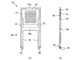
以下、本願の最良の実施形態について添付図面を参照して説明する。なお、便宜的に図1において、奥行、上下、及び左右方向を、折畳み椅子の前後、上下、及び左右方向として説明する。 Hereinafter, the best embodiment of the present application will be described with reference to the accompanying drawings. For convenience, in FIG. 1, the depth, the up and down, and the left and right directions are described as the front and rear, the up and down, and the left and right directions of the folding chair.
本実施形態の折畳み椅子30は、例えば、アルミニウムやSUS等の金属材料の削り出しにより形成され、図2(b)に示すように利用者が着座するための平板状の座板31と、この座板31を支持する支持脚33と、を備えており、図1(b)に示すように、折畳み椅子を展開した状態から、側面視で平坦状に折畳むことが可能になっている。
The folding
支持脚33は、側面視で略「X」字状の左右一対のX脚で構成され、各X脚は支軸34(本願の第1の支軸)を介して相互に回動脚自在に連結した短脚体36(本願の第2のフレーム)及び長脚体37(本願の第1のフレーム)を備えている。左右の短脚体36は、図1(a)に示すように、正面視で略H字状になるように短脚用連結体36aにより連結される。一方、左右の長脚体37は、上端が架け渡されるように長脚用連結体37aにより連結される。また、図1(a)及び図2(a)に示すように、正面視において、左右の短脚体36の幅は、左右の長脚体37の幅よりも狭く形成されており、長脚体37の内側に短脚体36が配置されている。
The
短脚体36及び長脚体37の下端部先端には、溝が形成され、この溝には、樹脂等で形成される弾性体38が、短脚体36及び長脚体37を水平方向に貫通する支持ピン39により取り付けられている。弾性体38は、当該短脚体36及び長脚体37の先端部よりも下方に突出するように取り付けられており、この弾性体38が床面と接触することで、床面との接触による傷つきが防止される。
A groove is formed at the tip of the lower end of the
また、支軸34は、左右の内側に位置する短脚体36と外側に位置する長脚体37とを貫通するピン状の部材が抜け止めされることで取り付けられている。
Further, the
左右の短脚体36は、上端部において支軸41を介して相互に回動自在に座板31の前方部が連結されている。この支軸41は、座板31の前方両側端部から外側に突出して設けられたピン状の部材であり、短脚体36を貫通して抜け止めされることで取り付けられている。
The left and right
座板31は、短脚体36と長脚体37の下端を揃えた状態において、短脚体36と長脚体37とで囲まれる領域に収まるように略方形に形成されている。座板31の両側下端部(側面視では前方部)は、短脚体36の幅に合わせて狭まるように段差を有して形成されている。また、その上端部(側面視では後方部)の中央には、図1(a)に示すように、使用者の持ち運び易さを考慮して空間を有するように凹部42が形成されている。
The
左右の長脚体37には、上方部に軸線に沿って長孔45(本願の係合部)が形成されており、座板31の後方部は支軸46(本願の第2の支軸)を介して当該左右の長脚体37に形成されている長孔45と係合して左右の長脚体37に取り付けられている。そして、折畳み椅子30を展開した状態において、この支軸46は、長孔45の下端部に位置し、折畳み椅子30を閉じると、支軸46が長孔45の上方へと移動し、完全に折畳み椅子30を閉じた状態において、この支軸46は、長孔45の上端部に位置する。この支軸46は、座板31の後方両側端部から外側に突出して設けられたピン状の部材であり、例えば、その周囲には樹脂等により形成された弾性部材が取り付けられ、長孔45の内側を摺動しつつ移動する。
A long hole 45 (engagement portion of the present application) is formed in the upper portion of the left and right
また、座板31の両側前後に設けられている支軸41、46間の側面部には、その両側端部から外側に水平方向に突出する突起体50が回転可能に設けられており、折畳み椅子30を閉じて後方の支軸46が長孔45の上端部に配置され、座板31と長脚体37とが完全に重なる際に、当該突起体50が長脚体37の端部を乗り越えて長孔45と係合する。この係合によって、座板31が回動することを防止し、折り畳まれた状態を維持可能となっている。これにより、折畳み椅子30を持ち運ぶ際に、折畳み椅子30が展開することを防止することが可能である。
Further, on the side surface portion between the
また、座板31及び支持脚33の厚みを同一とすることで、折畳み椅子30を閉じた状態において、同幅で平坦状に折畳まれることになり、収容体10に折畳み椅子30が収容された際に、折畳み椅子を載置する載置面との接触面積を大きくとることができるのでずれにくく載置しておくことが可能である。
Further, by making the
ここで、図1及び図2を用いて、折畳み椅子30の折り畳み動作について説明する。図6に示す展開状態では、座板31が水平状態に支持脚33によって支持され、長脚体37が座板31に対して直角からやや開いた状態にある。このとき、短脚体36及び長脚体37は「X」字状に開いた状態に保持される。そして、この状態から、座板31の後方部を上方に持ち上げると、支軸46が長孔45を上方へと移動し、座板31と短脚体36とが徐々に一直線状に近づきつつ、短脚体36と長脚体37とが閉脚しようとする。
Here, the folding operation of the
さらに、座板31と短脚体36とが長脚体37と重なるように折り畳むと、閉脚動作が更に進み、突起体50が長脚体37の端部を乗り越えて長孔45と係合し、短脚体36、座板31、及び長脚体37が完全に重なり、折畳み動作は終了する。逆の手順で、折畳み椅子30が閉じた状態から、座板31の前方部を前方へと引き出すと、短脚体36と長脚体37とが「X」字状に開き、折畳み椅子30は展開される。
Further, when the
以上に説明したように、本実施形態の折畳み椅子は、折り畳まれた状態から椅子として機能するように組み立てることが簡単にできる。一方で、椅子として組み立てられた状態から、簡単に折り畳むことが可能である。 As described above, the folding chair of this embodiment can be easily assembled so as to function as a chair from the folded state. On the other hand, it can be easily folded from the state assembled as a chair.
また、本実施形態の折畳み椅子30は、折り畳まれた状態において、全体が略平坦状に形成される。よって、狭い隙間にすっきりと収めることができ、見栄えがよい。また、載置面に対して座板31の面が接触するように配置することで、面接触により載置面に対してずれにくく載置しておくことが可能である。また、座板31の後端に凹部42を設けることで、長脚用連結体37aの中央部を取手として用いることができるので、取り出し易く且つ持ち運び等において作業性が良い。
Moreover, the
なお、本願は本実施形態に限定されるものではなく、種々の形態にて実施することが可能である。例えば、本実施形態の機構を用いて、背もたれなしの折畳み椅子としても構わない。このようにすれば、折畳み椅子の小型化が図れ、座板を高めに設定することが可能となる。 In addition, this application is not limited to this embodiment, It can implement in a various form. For example, a folding chair without a backrest may be used by using the mechanism of this embodiment. If it does in this way, size reduction of a folding chair can be achieved and it will become possible to set a seat board high.
また、長脚体37に形成される長孔は溝等であっても構わない。
Further, the long hole formed in the
30 折畳み椅子
36 短脚体
37 長脚体
34、46 支軸
45 長孔
30
上記課題を解決するために、請求項1に記載の折畳み椅子(30)は、左右一対の第1のフレーム(37)と、当該第1のフレームに第1の支軸(34)を介して回動可能に連結された左右一対の第2のフレーム(36)と、前記第2のフレームに前方が回動可能に連結され、前記第1のフレームに後方が第2の支軸(46)を介して回動可能に連結された座板(31)と、を具備し、前記第1のフレームには、前記第2の支軸が係合する係合部(45)が形成され、前記係合部は、前記第1フレームの軸線に沿って形成されており、前記第1のフレームに対する前記第2のフレームの開閉動作に応じて、前記第2の支軸がこの係合部を移動することを特徴とする。 In order to solve the above problem, the folding chair (30) according to claim 1 includes a pair of left and right first frames (37) and a first support shaft (34) connected to the first frame. A pair of left and right second frames (36) connected to each other so as to be able to rotate, and a front part of the second frame is connected to the second frame so as to be rotatable, and a rear part of the first frame is connected to the first frame (46). comprising a, and pivotally linked seat plate (31) through, wherein the first frame, prior Symbol engaging portion which the second shaft engaging (45) is formed, the engaging portion is formed along the axis of the first frame, in accordance with the opening and closing operation of the second frame for the first frame, prior Symbol second shaft is the engagement portion It is characterized by moving.
また、請求項2に記載の折畳み椅子は、請求項1に記載の折畳み椅子において、前記座板の側面には、前記第1のフレームに対する前記第2のフレームの折り畳み動作によって、前記係合部に係合する突起体(50)が設けられていることを特徴とする。 Further, the folding chair according to claim 2 is the folding chair according to claim 1 , wherein the engaging portion is formed on a side surface of the seat plate by a folding operation of the second frame with respect to the first frame. A protrusion (50) is provided to engage with.
また、請求項3に記載の折畳み椅子は、請求項1、又は2に記載の折畳み椅子において、前記支持体と前記座板との間には、取手として機能させるための隙間(42)を有していることを特徴とする。 The chair folding according to claim 3, Yes in the folding chair according to claim 1 or 2, between the seat plate and the support gap to function as a handle (42) It is characterized by that.
Claims (4)
当該第1のフレームに第1の支軸を介して回動可能に連結された左右一対の第2のフレームと、
前記第2のフレームに前方が回動可能に連結され、前記第1のフレームに後方が第2の支軸を介して回動可能に連結された座板と、を具備し、
前記第1のフレームには、前記第1の支軸又は前記第2の支軸が係合する係合部が形成され、前記係合部は、前記第1のフレームの軸線に沿って形成されており、前記第1のフレームに対する前記第2のフレームの開閉動作に応じて、前記第1又は第2の支軸がこの係合部を移動することを特徴とする折畳み椅子。 A pair of left and right first frames;
A pair of left and right second frames rotatably connected to the first frame via a first support shaft;
A front plate rotatably connected to the second frame and a back plate rotatably connected to the first frame via a second support shaft;
The first frame is formed with an engaging portion with which the first support shaft or the second support shaft is engaged, and the engaging portion is formed along the axis of the first frame. The folding chair is characterized in that the first or second support shaft moves in the engaging portion in accordance with the opening / closing operation of the second frame with respect to the first frame.
Priority Applications (1)
| Application Number | Priority Date | Filing Date | Title |
|---|---|---|---|
| JP2012241169A JP5393865B2 (en) | 2012-10-31 | 2012-10-31 | Folding chair |
Applications Claiming Priority (1)
| Application Number | Priority Date | Filing Date | Title |
|---|---|---|---|
| JP2012241169A JP5393865B2 (en) | 2012-10-31 | 2012-10-31 | Folding chair |
Publications (2)
| Publication Number | Publication Date |
|---|---|
| JP2013106945A true JP2013106945A (en) | 2013-06-06 |
| JP5393865B2 JP5393865B2 (en) | 2014-01-22 |
Family
ID=48704329
Family Applications (1)
| Application Number | Title | Priority Date | Filing Date |
|---|---|---|---|
| JP2012241169A Active JP5393865B2 (en) | 2012-10-31 | 2012-10-31 | Folding chair |
Country Status (1)
| Country | Link |
|---|---|
| JP (1) | JP5393865B2 (en) |
Cited By (1)
| Publication number | Priority date | Publication date | Assignee | Title |
|---|---|---|---|---|
| JP2015093151A (en) * | 2013-11-14 | 2015-05-18 | センターピア株式会社 | Folding chair |
Citations (2)
| Publication number | Priority date | Publication date | Assignee | Title |
|---|---|---|---|---|
| JPS52111209U (en) * | 1976-02-20 | 1977-08-24 | ||
| JP3054624U (en) * | 1998-06-02 | 1998-12-08 | 秀人 井上 | Folding chair that doubles as a carrier |
-
2012
- 2012-10-31 JP JP2012241169A patent/JP5393865B2/en active Active
Patent Citations (2)
| Publication number | Priority date | Publication date | Assignee | Title |
|---|---|---|---|---|
| JPS52111209U (en) * | 1976-02-20 | 1977-08-24 | ||
| JP3054624U (en) * | 1998-06-02 | 1998-12-08 | 秀人 井上 | Folding chair that doubles as a carrier |
Cited By (1)
| Publication number | Priority date | Publication date | Assignee | Title |
|---|---|---|---|---|
| JP2015093151A (en) * | 2013-11-14 | 2015-05-18 | センターピア株式会社 | Folding chair |
Also Published As
| Publication number | Publication date |
|---|---|
| JP5393865B2 (en) | 2014-01-22 |
Similar Documents
| Publication | Publication Date | Title |
|---|---|---|
| EP2668872B1 (en) | Composite chair | |
| CN113586596A (en) | Internal folding type hinge structure with flexible display panel | |
| JP5393865B2 (en) | Folding chair | |
| JP6276974B2 (en) | Folding chair | |
| US20140070574A1 (en) | Linkage for a foldable high chair | |
| KR20150022333A (en) | Combine chair and high chair | |
| JP2013154043A (en) | Folding chair | |
| JP2025015665A (en) | Toy component and doll toy | |
| JP5935398B2 (en) | Chair | |
| JP6069255B2 (en) | Door structure and dishwasher | |
| JP6201169B1 (en) | Folding stand mirror | |
| TWM491101U (en) | Hinge composed of plural moveable joints | |
| JP3226743U (en) | Folding table | |
| JP2010253233A (en) | Dressing table | |
| JP6082569B2 (en) | Container and container with folding chair | |
| JP4261499B2 (en) | Vehicle table structure | |
| KR102161678B1 (en) | Chair for infant | |
| CN209769748U (en) | Sofa bed | |
| JP5830505B2 (en) | Front panel structure | |
| ITBZ20010008U1 (en) | UPHOLSTERED SEAT FURNITURE. | |
| JP2005087232A (en) | Furniture with auxiliary top plate | |
| JP2002223884A (en) | Chair | |
| KR20160025129A (en) | Variableness type sofa | |
| KR100545799B1 (en) | Backrest chair | |
| JP2008110147A (en) | table |
Legal Events
| Date | Code | Title | Description |
|---|---|---|---|
| A521 | Request for written amendment filed |
Free format text: JAPANESE INTERMEDIATE CODE: A523 Effective date: 20130411 |
|
| A621 | Written request for application examination |
Free format text: JAPANESE INTERMEDIATE CODE: A621 Effective date: 20130411 |
|
| A871 | Explanation of circumstances concerning accelerated examination |
Free format text: JAPANESE INTERMEDIATE CODE: A871 Effective date: 20130411 |
|
| A975 | Report on accelerated examination |
Free format text: JAPANESE INTERMEDIATE CODE: A971005 Effective date: 20130510 |
|
| A131 | Notification of reasons for refusal |
Free format text: JAPANESE INTERMEDIATE CODE: A131 Effective date: 20130604 |
|
| A521 | Request for written amendment filed |
Free format text: JAPANESE INTERMEDIATE CODE: A523 Effective date: 20130805 |
|
| TRDD | Decision of grant or rejection written | ||
| A01 | Written decision to grant a patent or to grant a registration (utility model) |
Free format text: JAPANESE INTERMEDIATE CODE: A01 Effective date: 20130917 |
|
| A61 | First payment of annual fees (during grant procedure) |
Free format text: JAPANESE INTERMEDIATE CODE: A61 Effective date: 20131015 |
|
| R150 | Certificate of patent or registration of utility model |
Ref document number: 5393865 Country of ref document: JP Free format text: JAPANESE INTERMEDIATE CODE: R150 Free format text: JAPANESE INTERMEDIATE CODE: R150 |
|
| R250 | Receipt of annual fees |
Free format text: JAPANESE INTERMEDIATE CODE: R250 |
|
| R250 | Receipt of annual fees |
Free format text: JAPANESE INTERMEDIATE CODE: R250 |
|
| R250 | Receipt of annual fees |
Free format text: JAPANESE INTERMEDIATE CODE: R250 |
|
| R250 | Receipt of annual fees |
Free format text: JAPANESE INTERMEDIATE CODE: R250 |
|
| R250 | Receipt of annual fees |
Free format text: JAPANESE INTERMEDIATE CODE: R250 |
|
| R250 | Receipt of annual fees |
Free format text: JAPANESE INTERMEDIATE CODE: R250 |