JP2013123723A - Continuous coil cooling system - Google Patents
Continuous coil cooling system Download PDFInfo
- Publication number
- JP2013123723A JP2013123723A JP2011272806A JP2011272806A JP2013123723A JP 2013123723 A JP2013123723 A JP 2013123723A JP 2011272806 A JP2011272806 A JP 2011272806A JP 2011272806 A JP2011272806 A JP 2011272806A JP 2013123723 A JP2013123723 A JP 2013123723A
- Authority
- JP
- Japan
- Prior art keywords
- skid
- coil
- carry
- water tank
- fixed
- Prior art date
- Legal status (The legal status is an assumption and is not a legal conclusion. Google has not performed a legal analysis and makes no representation as to the accuracy of the status listed.)
- Granted
Links
Images

Landscapes
- Winding, Rewinding, Material Storage Devices (AREA)
- Heat Treatment Of Strip Materials And Filament Materials (AREA)
Abstract
【課題】大掛かりな温度管理システムが不要で、メンテナンスの費用も抑制できる連続式冷却装置を提供する。
【解決手段】水槽1内に列設方向に沿って配設されコイル2を浸漬した状態で保持可能な複数の固定スキッド3と、列設方向の一方における水槽1よりも外側の搬入位置でコイル2を保持可能な搬入スキッド5と、列設方向の他方における水槽1よりも外側の搬出位置でコイル2を保持可能な搬出スキッド7と、列設方向に沿って並び且つ列設方向に沿って進退可能な複数の移動体と、移動体の夫々に支持された状態で昇降可能で且つコイル2を保持可能な可動スキッド11とを備える。そして、移動体の進退及び可動スキッド11の昇降により、搬入スキッド5と固定スキッド3との間、固定スキッド3同士の間、及び固定スキッド3と搬出スキッド7との間で、列設方向の一方から他方に向けて順にコイル2を移動させる。
【選択図】図1The present invention provides a continuous cooling device that does not require a large-scale temperature management system and can reduce maintenance costs.
SOLUTION: A plurality of fixed skids 3 arranged along a row direction in a water tank 1 and capable of holding the coil 2 in a dipped state, and a coil at a carry-in position outside the water tank 1 in one side of the row direction. 2, a carry-in skid 5 that can hold 2, a carry-out skid 7 that can hold the coil 2 at the carry-out position outside the water tank 1 on the other side in the row direction, and a row along the row direction. A plurality of movable bodies that can advance and retreat, and a movable skid 11 that can move up and down while being supported by each of the movable bodies and can hold the coil 2 are provided. Then, by moving the movable body forward and backward and raising and lowering the movable skid 11, one side in the row direction between the carry-in skid 5 and the fixed skid 3, between the fixed skids 3, and between the fixed skid 3 and the carry-out skid 7. The coil 2 is moved sequentially from one to the other.
[Selection] Figure 1
Description
本発明は、熱間圧延後に巻き取られたコイルを冷却する連続式コイル冷却装置に関するものである。 The present invention relates to a continuous coil cooling apparatus for cooling a coil wound up after hot rolling.
熱間圧延されて巻き取られたコイルは、出荷や次工程までに常温近くまで冷却する必要がある。一般的には、熱延工場に併設されたコイルヤードで空冷されるが、次工程や客先へのリードタイムを短縮するために水冷する場合もある。コイルの水冷には、次のような方法が知られている。
先ず、コイルヤードのスキッド毎にノズルを設け、コイルに対してノズルから冷却水を噴霧又は噴射する方法がある(特許文献1、2参照)。また、冷却水を溜めた水槽にコイルを浸漬する方法もある(特許文献3参照)。
The coil that is hot-rolled and wound up needs to be cooled to near room temperature before shipment or the next process. Generally, it is air-cooled in a coil yard attached to a hot rolling factory, but may be water-cooled to shorten the lead time to the next process or customer. The following methods are known for water cooling of the coil.
First, there is a method in which a nozzle is provided for each coil yard skid, and cooling water is sprayed or injected from the nozzle to the coil (see Patent Documents 1 and 2). There is also a method of immersing the coil in a water tank in which cooling water is stored (see Patent Document 3).
コイルに冷却水を噴霧又は噴射したり、コイルを水槽に浸漬したりする方法では、冷却前と冷却後にコイルを搬送する際にクレーンが使用されるが、こうした冷却設備では水蒸気が充満しているため、クレーンが腐食しやすく、メンテナンスの費用が高くなってしまう。また、設備自体も老朽化しやすい。
さらに、冷却するためヤードのうち、空いた番地にコイルをランダムに置いてゆくと、コイル毎に冷却時間を計測しなければならないため、温度管理のシステムが大掛かりになってしまう。
本発明の課題は、大掛かりな温度管理システムが不要で、メンテナンスの費用も抑制できる連続式冷却装置を提供することである。
In the method of spraying or spraying cooling water on the coil or immersing the coil in the water tank, a crane is used to transport the coil before and after cooling, but such cooling equipment is filled with water vapor. Therefore, the crane is easily corroded, and the cost of maintenance becomes high. Also, the equipment itself is prone to aging.
Furthermore, if the coil is randomly placed in a vacant address in the yard for cooling, the cooling time must be measured for each coil, so that the temperature management system becomes large.
An object of the present invention is to provide a continuous cooling device that does not require a large-scale temperature management system and that can suppress maintenance costs.
本発明の一態様に係る連続式コイル冷却装置では、冷却水を貯留し、水平面における予め設定した列設方向に沿って複数のコイルを浸漬可能な水槽と、列設方向に沿って水槽内に配設され、コイルを浸漬させた状態で保持可能な複数の固定スキッドと、列設方向の一方側であり水槽よりも外側の搬入位置で、水槽に搬入する前のコイルを保持可能な搬入スキッドと、列設方向の他方側であり水槽よりも外側の搬出位置で、水槽から搬出した後のコイルを保持可能な搬出スキッドと、少なくとも水槽に貯留された冷却水の外で、列設方向に沿って並び、且つ列設方向に沿って進退可能な複数の移動体と、移動体の夫々に支持された状態で、昇降可能で、且つコイルを保持可能な可動スキッドと、を備え、移動体の進退、及び可動スキッドの昇降により、搬入スキッドと固定スキッドとの間、固定スキッド同士の間、及び固定スキッドと搬出スキッドとの間で、列設方向の一方から他方に向けて順にコイルを移動させることを特徴とする。 In the continuous coil cooling apparatus according to one aspect of the present invention, the cooling water is stored, and a water tank capable of immersing a plurality of coils along a preset arrangement direction in a horizontal plane, and a water tank along the arrangement direction. A plurality of fixed skids that can be held in a state where the coils are immersed, and a carry-in skid that can hold the coil before being carried into the water tank at a carry-in position on one side in the arrangement direction and outside the water tank And at the carry-out position on the other side in the row direction and outside the water tank, a carry-out skid capable of holding the coil after being carried out from the water tank, and at least outside the cooling water stored in the water tank, in the row direction. And a movable skid that can be moved up and down and can hold a coil while being supported by each of the movable bodies. Back and forth, and moving skids up and down More, between the carry-skid and the fixed skid, between the stationary skids each other, and between the fixed skid and unloading skid, characterized in that to turn move the coil toward the other from one row arrangement direction.
本発明の一態様に係る連続式コイル冷却装置では、固定スキッド、搬入スキッド、及び搬出スキッドは、コイルにおける軸方向の中央を保持し、可動スキッドは、コイルにおける軸方向の両端側を保持することを特徴とする。
本発明の一態様に係る連続式コイル冷却装置では、搬入スキッドは、搬入位置までコイルを搬入する搬入台車に搭載され、搬出スキッドは、搬出位置からコイルを搬出する搬出台車に搭載されることを特徴とする。
本発明の一態様に係る連続式コイル冷却装置では、可動スキッドは、移動体との間に介装された伸縮機構の伸縮により、上下方向に昇降可能に構成され、伸縮機構は、少なくとも水槽に貯留された冷却水の外に配置されることを特徴とする。
In the continuous coil cooling device according to one aspect of the present invention, the fixed skid, the carry-in skid, and the carry-out skid hold the center in the axial direction of the coil, and the movable skid holds both ends of the coil in the axial direction. It is characterized by.
In the continuous coil cooling apparatus according to one aspect of the present invention, the carry-in skid is mounted on a carry-in carriage that carries the coil to the carry-in position, and the carry-out skid is loaded on the carry-out carriage that carries the coil from the carry-out position. Features.
In the continuous coil cooling apparatus according to one aspect of the present invention, the movable skid is configured to be movable up and down in the vertical direction by expansion and contraction of an expansion and contraction mechanism interposed between the movable body and the expansion and contraction mechanism at least in the water tank. It is arranged outside the stored cooling water.
本発明の一態様に係る連続式コイル冷却装置によれば、コイルをスキッド上に載せるためのクレーン設備が不要となるので、メンテナンスの費用を抑制することができる。また、搬入側から搬出側へと順に移動させてゆくので、水槽への浸漬時間によって冷却後のコイル温度が求まるので、大掛かりな温度管理システムも不要となる。 According to the continuous coil cooling device concerning one mode of the present invention, since the crane equipment for putting a coil on a skid becomes unnecessary, the cost of maintenance can be controlled. Further, since the coil is moved in order from the carry-in side to the carry-out side, the coil temperature after cooling is determined by the immersion time in the water tank, so that a large temperature management system is not required.
以下、本発明の実施形態を図面に基づいて説明する。
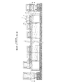
図1は、連続式コイル冷却装置の全体図である。
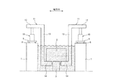
図2は、水槽の断面図である。
水槽1には、冷却水を貯留してあり、この水槽1は、水平面における予め設定した設定した列設方向に沿って複数のコイル2を浸漬するのに充分な深さと広さがある。水槽1内の底面には、コイル2を浸漬した状態で保持可能な複数の固定スキッド3を、列設方向に沿って固定している。なお、列設方向の一方を搬入側と定義し、他方を搬出側と定義し、さらに水平面上で列設方向と直交する方向を幅方向と定義する。
Hereinafter, embodiments of the present invention will be described with reference to the drawings.
FIG. 1 is an overall view of a continuous coil cooling apparatus.
FIG. 2 is a cross-sectional view of the water tank.
Cooling water is stored in the water tank 1, and the water tank 1 has a depth and width sufficient to immerse the plurality of
固定スキッド3の上面には、幅方向から見て、略V字形の溝が形成されており、幅方向にコイル2の軸方向を合わせた状態で、固定スキッド3の溝にコイル2を載置できる。複数の固定スキッド3のうち、列設方向の両端に位置するものは、コイル2を水面近傍で保持する高さに設定されており、それ以外のものは、コイル2の全体を水中に浸漬させた状態で保持する高さに設定されている。
A substantially V-shaped groove is formed on the upper surface of the fixed
固定スキッド3は、水槽1における幅方向の略中央に固定してある。固定スキッド3の幅方向長さは、コイル2の軸方向長さよりも短く設定されており、固定スキッド3は、コイル2の軸方向中央を保持する。
列設方向の搬入側で、水槽1よりも外側では、所定の軌道に沿って搬入台車4が走行する。この搬入台車4には、コイル2を保持可能な搬入スキッド5が搭載されており、この搬入スキッド5に冷却前のコイル2を載置して予め設定した搬入位置まで搬入する。この搬入位置とは、搬入スキッド5が前述した固定スキッド3と同列となる位置である。
The
On the carry-in side in the row direction, outside the water tank 1, the carry-in cart 4 travels along a predetermined track. A loading skid 5 capable of holding the
搬入スキッド5の上面には、幅方向から見て、略V字形の溝が形成されており、幅方向にコイル2の軸方向を合わせた状態で、搬入スキッド5の溝にコイル2を載置できる。この搬入スキッド5におけるコイル2の保持位置は、固定スキッド3のうち、列設方向における最も搬入側に位置するものと同等である。つまり、水槽1に貯留された冷却水の水位近傍でコイル2を保持する高さに設定されている。
搬入スキッド5の幅方向長さは、コイル2の軸方向長さよりも短く設定されており、搬入スキッド5は、コイル2の軸方向中央を保持する。
A substantially V-shaped groove is formed on the upper surface of the carry-in skid 5 when viewed from the width direction, and the
The width in the width direction of the carry-in skid 5 is set shorter than the length in the axial direction of the
列設方向の搬出側で、水槽1よりも外側では、所定の軌道に沿って搬出台車6が走行する。この搬出台車6には、コイル2を保持可能な搬出スキッド7が搭載されており、この搬出スキッド7に冷却後のコイル2を載置して予め設定した搬出位置から搬出する。この搬出位置とは、搬出スキッド7が前述した固定スキッド3と同列となる位置である。
On the carry-out side in the line-up direction and outside the water tank 1, the carry-out carriage 6 travels along a predetermined track. A carry-out skid 7 that can hold the
搬出スキッド7の上面には、幅方向から見て、略V字形の溝が形成されており、幅方向にコイル2の軸方向を合わせた状態で、搬出スキッド7の溝にコイル2を載置できる。この搬出スキッド7におけるコイル2の保持位置は、固定スキッド3のうち、列設方向における最も搬出側に位置するものと同等である。つまり、水槽1に貯留された冷却水の水位近傍でコイル2を保持する高さに設定されている。
搬出スキッド7の幅方向長さは、コイル2の軸方向長さよりも短く設定されており、搬出スキッド7は、コイル2の軸方向中央を保持する。
A substantially V-shaped groove is formed on the upper surface of the carry-out skid 7 when viewed from the width direction, and the
The length in the width direction of the carry-out skid 7 is set to be shorter than the length in the axial direction of the
水槽1を構成する幅方向両端の側壁上面には、夫々、列設方向に沿って延びる一対のレール8が敷設されており、この一対のレール8に沿って複数の移動体9が進退する。レール8は、列設方向の長さが、水槽1の長さよりも長く、搬入側は、少なくとも搬入位置にある搬入スキッド5の上方にまで延在し、搬出側は、少なくとも搬出位置にある搬出スキッド7の上方にまで延在する。
この移動体9は、水槽1に貯留された冷却水を挟んで幅方向で対向する、つまり対岸に位置する移動体9同士が一対となり、同期して進退する。
A pair of
The
幅方向で一対の移動体9は、列設方向に、固定スキッド3の数量よりも一組だけ多い台数が並べてある。したがって、搬入スキッド5及び各固定スキッド3に対応する位置に、夫々、一対の移動体9を配置させると、搬出スキッド7に対応する位置だけ、一対の移動体9がない空車状態となる。この幅方向で一対となる夫々の移動体9を、搬入スキッド5及び各固定スキッド3に対応させて、搬入側に寄せた状態をコイル受け取り状態と称す。一方、各固定スキッド3及び搬出スキッド7に対応する位置に、夫々、一対の移動体9を配置させると、搬入スキッド5に対応する位置だけ、一対の移動体9がない空車状態となる。この幅方向で一対となる夫々の移動体9を、各固定スキッド3及び搬出スキッド7に対応させて、搬入側に寄せた状態をコイル受け渡し状態と称す。
The pair of
移動体9は、進退方向に離れた前輪車軸及び後輪車軸を有し、計4つの車輪を介してレール8に接地している。また、移動体9には、進退方向に離れた2箇所に、上下方向に伸縮可能な昇降用シリンダ10を設けている。
昇降用シリンダ10の上端には、昇降用シリンダ10(伸縮機構)の伸縮に伴って昇降し、コイル2を保持可能な可動スキッド11を設けている。
可動スキッド11は、昇降用シリンダ10の上端に固定され水槽1の幅方向内側に延びる水平フレーム12と、この水平フレーム12の幅方向内側から下方に延びる垂直フレーム13と、この垂直フレーム13の下端から幅方向内側に延びるスキッドフレーム14と、を備える。
なお、幅方向で一対の移動体9は、夫々、水平フレーム12同士を連結してもよく、これによれば構造的な強度が増す。
The moving
A
The
Note that the pair of moving
幅方向で対向する一対の垂直フレーム13は、幅方向における内周面同士の距離が、コイル2の軸方向の長さよりも大きく、幅方向における外周面同士の距離が、水槽1を構成する側壁同士の距離よりも小さくなるように設定されている。これにより、水槽1の幅方向の一端側において、垂直フレーム13は、固定スキッド3に載置したコイル2と、水槽1を構成する側壁との隙間を、コイル2及び水槽1を構成する側壁に接触(干渉)することなく、列設方向及び上下方向に移動することができる。
The pair of
幅方向で対向する一対のスキッドフレーム14は、幅方向の内側に向いた先端同士の距離が、固定スキッド3の幅よりも大きくなるように設定されている。これにより、スキッドフレーム14は、固定スキッド3に接触(干渉)することなく、列設方向及び上下方向に移動することができる。
幅方向で対向する一対のスキッドフレーム14は、幅方向の内側に向いた先端同士の距離が、コイル2の軸方向長さよりも小さくなるように設定されており、スキッドフレーム14の上面には、幅方向から見て、略V字形の溝が形成されている。これにより、幅方向にコイル2の軸方向を合わせた状態で、コイル2の軸方向両側を、幅方向で対向する一対のスキッドフレーム14の溝に載置できる。
上記のレール8、移動体9、昇降用シリンダ10等は、少なくとも水槽1に貯留された冷却水の外に配置する。これにより、レール8、移動体9、昇降用シリンダ10等の防水処理を省くことができる。
The pair of skid frames 14 facing each other in the width direction are set such that the distance between the tips facing inward in the width direction is larger than the width of the fixed
The pair of skid frames 14 facing each other in the width direction is set such that the distance between the tips facing inward in the width direction is smaller than the axial length of the
The
一方、固定スキッド3、スキッドフレーム14等は、水槽1に貯留された冷却水の中に浸すため、防水処理や防錆処理を必要とする。
各移動体9の進退、及び昇降用シリンダ10の伸縮は、図示しない制御装置によって駆動制御される。
制御装置は、搬入スキッド5と最も搬入側に位置する固定スキッド3との間、隣接する固定スキッド3同士の間、及び最も搬出側に位置する固定スキッド3と搬出スキッド7との間で、列設方向の搬入側から搬出側に向けて順にコイル2を移動させる。
On the other hand, since the fixed
Advancing / retreating of each moving
The controller is arranged between the carry-in skid 5 and the fixed
ここで、動作について説明する。
図3は、移動体9及び昇降用シリンダ10の動作について説明した図である。
図中の(a)では、固定スキッド3にコイル2を載置しており、この固定スキッド3に対して移動体9は列設方向の搬入側にある。また、スキッドフレーム14の上面が、コイル2の下部よりも下方となるように、昇降用シリンダ10は収縮させてある。この状態から移動体9をレール8に沿って搬出側に前進させる。このとき、垂直フレーム13及びスキッドフレーム14がコイル2及び固定スキッド3に接触(干渉)することはない。
Here, the operation will be described.
FIG. 3 is a diagram illustrating the operation of the moving
In (a) in the figure, the
図中の(b)では、移動体9がレール8に沿って搬出側に前進したことで、固定スキッド3と移動体9とが列設方向の同一位置にある。すなわち、固定スキッド3に載置されたコイル2の真下にスキッドフレーム14がある。この状態から昇降用シリンダ10を伸張させる。このとき、垂直フレーム13及びスキッドフレーム14が固定スキッド3に接触(干渉)することはないが、スキッドフレーム14の上面がコイル2の下部に当接する。したがって、コイル2が固定スキッド3に載置された状態からスキッドフレーム14に載置された状態へと切り替る。
In (b) in the figure, the fixed
図中の(c)では、昇降用シリンダ10を伸張させたことで、スキッドフレーム14の上昇に伴ってコイル2が上昇する。このとき、コイル2が冷却水の水面から露出することはなく、冷却水に浸漬した状態を維持しており、且つコイル2の下部が固定スキッド3の上面よりも上方となる。この状態から移動体9をレール8に沿って搬出側に前進させる。このとき、垂直フレーム13及びスキッドフレーム14がコイル2及び固定スキッド3に接触(干渉)することはなく、且つコイル2が固定スキッド3に接触(干渉)することはない。
In (c) in the figure, the
そして、移動体9をレール8に沿って搬出側に前進させて、隣接する搬出側の固定スキッド3と移動体9とを列設方向の同一位置にする。すなわち、コイル2が載置されていない固定スキッド3の真上にスキッドフレーム14を配置させる。この状態から昇降用シリンダ10を収縮させる。このとき、垂直フレーム13及びスキッドフレーム14が固定スキッド3に接触(干渉)することはないが、コイル2の下部が固定スキッド3の上面に当接する。したがって、コイル2がスキッドフレーム14に載置された状態から固定スキッド3に載置された状態へと切り替る。この状態から移動体9をレール8に沿って搬入側に後退させる。このとき、垂直フレーム13及びスキッドフレーム14がコイル2及び固定スキッド3に接触(干渉)することはない。
Then, the
ここでは、隣接する固定スキッド3同士の間、つまり水中で、搬出側に向けてコイル2を移動させる動作について説明したが、搬入スキッド5と最も搬入側に位置する固定スキッド3との間、及び最も搬出側に位置する固定スキッド3と搬出スキッド7との間で、搬出側に向けてコイル2を移動させる動作についても同様の手順を実行する。
なお、水中で搬出側に向けてコイル2を移動させる場合には、スキッドフレーム14の上面がコイル2の下部よりも下方となる位置を最下位とし、コイル2が冷却水の水面から露出することなく、且つコイル2の下部が固定スキッド3の上面よりも上方となる位置を最高位としている。こうした条件を満たすために、コイル2の直径を考慮しつつ、垂直フレーム13の上下方向長さ、昇降用シリンダ10のストローク量、固定スキッド3の高さ、スキッドフレーム14の上下方向厚み、水槽1の深さ、冷却水の水位等を設定する必要がある。
Here, the operation of moving the
In addition, when moving the
また、最も搬入側に位置する固定スキッド3とその次に搬入側に位置する固定スキッド3との間、及び最も搬出側に位置する固定スキッド3とその次に搬出側に位置する固定スキッド3との間で、搬出側に向けてコイル2を移動させる場合には、コイル2を水面近傍で保持する位置と、コイル2の全体を水中に浸漬させた状態で保持する位置との間で、スキッドフレーム14を昇降させる必要がある。したがって、水中で搬出側に向けてコイル2を移動させる場合よりも、昇降用シリンダ10のストローク量を確保しなければならない。
Further, between the fixed
また、搬入スキッド5と最も搬入側に位置する固定スキッド3との間、及び最も搬出側に位置する固定スキッド3と搬出スキッド7との間で、搬出側に向けてコイル2を移動させる場合には、水槽1を構成する列設方向両端の側壁を越えなければならない。したがって、水槽1を構成する列設方向両端の側壁の高さに応じて、昇降用シリンダ10のストローク量を設定する必要がある。
Further, when the
本実施形態では、幅方向で一対の移動体9は、列設方向に、固定スキッド3の数量よりも一組だけ多い台数が並べてある。それで、幅方向で一対となる夫々の移動体9を、搬入側に寄せたコイル受け取り状態と、搬入側に寄せたコイル受け渡し状態との間で、交互に進退させることで、列設方向の搬入側から搬出側に向けて順にコイル2を移動させることができる。
このように、従来のように広大な冷却用のコイルヤードの設備を不要とし、またコイル2をスキッド上に載せるためのクレーンの設備が不要となるので、メンテナンス費用の削減に繋がる。
In the present embodiment, the pair of moving
Thus, the need for a large cooling coil yard facility as in the prior art and a crane facility for placing the
また、冷却水で満たされた水槽1の中にコイル2を浸す冷却方法なので、冷却水を熱交換機などで適切な温度に保つことにより、従来のようにコイル2に冷却水を噴射又は噴霧したりする方法と比べて、次工程で処理可能となるコイル温度まで冷却するための所要時間が短縮されるので、顧客への納期も短縮することができる。
また、本設備では連続的にコイル2を冷却しているので、冷却開始時のコイル温度と水槽1内で滞留する時間とに基づいて、冷却後のコイル温度が計算によって求まるので、従来のようなコイルヤードでの大規模な温度管理システムを構築しなくてもよい。
In addition, since the
In addition, since the
また、移動体9、昇降用シリンダ10、可動スキッド11などを含めて、水槽1の全体を覆えば、水蒸気が設備環境に充満することを防ぐことができるので、屋内に設置する場合であっても、従来と比べて建屋自体の腐食を最小限に抑制することができる。したがって、建屋の補修費用を従来よりも抑制することができる。
本実施形態では、冷却前のコイル2を搬入位置まで搬入台車4によって搬入し、冷却後のコイル2を搬出位置まで搬出台車6によって搬出しているが、これに限定されるものではない。すなわち、搬入位置や搬出位置が、水蒸気の充満する環境でなければ、搬入位置までの搬入や、搬出位置からの搬出には、クレーンを使用してもよい。
Further, if the entire aquarium 1 including the moving
In this embodiment, the
また、本実施形態では、水槽1を構成する幅方向両端の側壁上面に、レール8を敷設しているが、これに限定されるものではない。要は、列設方向に沿って移動体9が進退できればよいので、水槽1以外の他の構造物、例えば屋内の床面等にレール8を敷設してもよい。
その他、本実施形態の趣旨を逸脱しない範囲で、各構成の数量、サイズ、形状等は任意に変更することができる。
Moreover, in this embodiment, although the
In addition, the quantity, size, shape, and the like of each component can be arbitrarily changed without departing from the spirit of the present embodiment.
1 水槽
2 コイル
3 固定スキッド
4 搬入台車
5 搬入スキッド
6 搬出台車
7 搬出スキッド
8 レール
9 移動体
10 昇降用シリンダ
11 可動スキッド
12 水平フレーム
13 垂直フレーム
14 スキッドフレーム
DESCRIPTION OF SYMBOLS 1
Claims (4)
前記列設方向に沿って前記水槽内に配設され、前記コイルを浸漬させた状態で保持可能な複数の固定スキッドと、
前記列設方向の一方側であり前記水槽よりも外側の搬入位置で、前記水槽に搬入する前の前記コイルを保持可能な搬入スキッドと、
前記列設方向の他方側であり前記水槽よりも外側の搬出位置で、前記水槽から搬出した後の前記コイルを保持可能な搬出スキッドと、
少なくとも前記水槽に貯留された冷却水の外で、前記列設方向に沿って並び、且つ前記列設方向に沿って進退可能な複数の移動体と、
前記移動体の夫々に支持された状態で、昇降可能で、且つ前記コイルを保持可能な可動スキッドと、を備え、
前記移動体の進退、及び前記可動スキッドの昇降により、前記搬入スキッドと前記固定スキッドとの間、前記固定スキッド同士の間、及び前記固定スキッドと前記搬出スキッドとの間で、前記列設方向の一方から他方に向けて順に前記コイルを移動させることを特徴とする連続式コイル冷却装置。 A water tank that stores cooling water and is capable of immersing a plurality of coils along a predetermined arrangement direction in a horizontal plane;
A plurality of fixed skids disposed in the water tank along the row direction and capable of being held in a state in which the coil is immersed;
A carry-in skid capable of holding the coil before being carried into the water tank at a carry-in position outside the water tank on one side in the row direction;
An unloading skid capable of holding the coil after unloading from the water tank at the unloading position on the other side of the row direction and outside the water tank;
Outside the cooling water stored in at least the water tank, a plurality of moving bodies arranged along the row direction and capable of moving back and forth along the row direction,
A movable skid capable of moving up and down and holding the coil in a state supported by each of the moving bodies,
By moving the movable body forward and backward, and raising and lowering the movable skid, between the loading skid and the fixed skid, between the fixed skids, and between the fixed skid and the unloading skid, A continuous coil cooling apparatus, wherein the coil is moved in order from one to the other.
前記可動スキッドは、前記コイルにおける軸方向の両端側を保持することを特徴とする請求項1に記載の連続式コイル冷却装置。 The fixed skid, the carry-in skid, and the carry-out skid hold an axial center of the coil,
The continuous coil cooling apparatus according to claim 1, wherein the movable skid holds both ends of the coil in the axial direction.
前記搬出スキッドは、前記搬出位置から前記コイルを搬出する搬出台車に搭載されることを特徴とする請求項1又は2に記載の連続式コイル冷却装置。 The carry-in skid is mounted on a carry-in carriage that carries the coil into the carry-in position,
The continuous coil cooling apparatus according to claim 1 or 2, wherein the carry-out skid is mounted on a carry-out carriage that carries out the coil from the carry-out position.
前記伸縮機構は、少なくとも前記水槽に貯留された冷却水の外に配置されることを特徴とする請求項1〜3の何れか一項に記載の連続式コイル冷却装置。
The movable skid is configured to be vertically movable by expansion and contraction of an expansion / contraction mechanism interposed between the movable body,
The continuous coil cooling device according to any one of claims 1 to 3, wherein the expansion and contraction mechanism is disposed at least outside the cooling water stored in the water tank.
Priority Applications (1)
| Application Number | Priority Date | Filing Date | Title |
|---|---|---|---|
| JP2011272806A JP5891767B2 (en) | 2011-12-13 | 2011-12-13 | Continuous coil cooling system |
Applications Claiming Priority (1)
| Application Number | Priority Date | Filing Date | Title |
|---|---|---|---|
| JP2011272806A JP5891767B2 (en) | 2011-12-13 | 2011-12-13 | Continuous coil cooling system |
Publications (2)
| Publication Number | Publication Date |
|---|---|
| JP2013123723A true JP2013123723A (en) | 2013-06-24 |
| JP5891767B2 JP5891767B2 (en) | 2016-03-23 |
Family
ID=48775302
Family Applications (1)
| Application Number | Title | Priority Date | Filing Date |
|---|---|---|---|
| JP2011272806A Expired - Fee Related JP5891767B2 (en) | 2011-12-13 | 2011-12-13 | Continuous coil cooling system |
Country Status (1)
| Country | Link |
|---|---|
| JP (1) | JP5891767B2 (en) |
Cited By (2)
| Publication number | Priority date | Publication date | Assignee | Title |
|---|---|---|---|---|
| CN103447316A (en) * | 2013-09-09 | 2013-12-18 | 中冶赛迪工程技术股份有限公司 | Temperature-controlling and cold-controlling method and process layout for final molding rolling of high-speed wire rods |
| JP2020069490A (en) * | 2018-10-30 | 2020-05-07 | 日本製鉄株式会社 | Steel slab cooling equipment and steel slab cooling method |
Citations (2)
| Publication number | Priority date | Publication date | Assignee | Title |
|---|---|---|---|---|
| JPS4897713A (en) * | 1972-03-27 | 1973-12-12 | ||
| JPH0228312U (en) * | 1988-08-05 | 1990-02-23 |
-
2011
- 2011-12-13 JP JP2011272806A patent/JP5891767B2/en not_active Expired - Fee Related
Patent Citations (2)
| Publication number | Priority date | Publication date | Assignee | Title |
|---|---|---|---|---|
| JPS4897713A (en) * | 1972-03-27 | 1973-12-12 | ||
| JPH0228312U (en) * | 1988-08-05 | 1990-02-23 |
Cited By (2)
| Publication number | Priority date | Publication date | Assignee | Title |
|---|---|---|---|---|
| CN103447316A (en) * | 2013-09-09 | 2013-12-18 | 中冶赛迪工程技术股份有限公司 | Temperature-controlling and cold-controlling method and process layout for final molding rolling of high-speed wire rods |
| JP2020069490A (en) * | 2018-10-30 | 2020-05-07 | 日本製鉄株式会社 | Steel slab cooling equipment and steel slab cooling method |
Also Published As
| Publication number | Publication date |
|---|---|
| JP5891767B2 (en) | 2016-03-23 |
Similar Documents
| Publication | Publication Date | Title |
|---|---|---|
| US9520313B2 (en) | Conveyance system and temporary storage method of articles in conveyance system | |
| CN101849025B (en) | Device and method for loading and unloading a heat treatment furnace | |
| US20160244260A1 (en) | Automated warehouse | |
| TWI382949B (en) | Item handling device | |
| TW201904854A (en) | Conveying system and conveying method | |
| CA2880217C (en) | Apparatus for moving slabs and store provided with such an apparatus | |
| JP2013178903A (en) | Secondary battery processing facility | |
| JP5891767B2 (en) | Continuous coil cooling system | |
| JP5399858B2 (en) | Heavy material conveyance mechanism and heavy material conveyance method using the same | |
| CN205274388U (en) | Guide tracked portable stereoscopic warehouse | |
| JP2011127187A (en) | Heat-treatment method and rapid cooling device for bar steel | |
| CN104480292B (en) | Cold-rolled strip coil tunnel type annealing furnace | |
| JP2013104115A (en) | In-furnace conveyance device and heating furnace | |
| CN211109640U (en) | Feeding and discharging mechanism for zinc spraying processing of cast pipe | |
| RU2671589C2 (en) | Moulding process line for moulding concrete products | |
| JP2015178396A (en) | Portal transportation storage apparatus and automatic storage/take-out type material storehouse | |
| US20170370648A1 (en) | Heat treatment system | |
| US9764898B2 (en) | Automated warehouse and operation method for same | |
| CN103668399B (en) | A kind of process unit universal for welding and coating of four doors of three-guarantees parts | |
| KR100885951B1 (en) | Dipping Cooling Device | |
| JP6448907B2 (en) | Overhead type transport storage device and automatic storage / removal type material storage | |
| JP5925952B1 (en) | Continuous furnace manufacturing method | |
| JP5901236B2 (en) | Pusher furnace | |
| TWI853674B (en) | Wire derusting equipment discharge device | |
| CN204237837U (en) | Cold-rolled strip coil tunnel type annealing furnace |
Legal Events
| Date | Code | Title | Description |
|---|---|---|---|
| A621 | Written request for application examination |
Free format text: JAPANESE INTERMEDIATE CODE: A621 Effective date: 20141027 |
|
| A977 | Report on retrieval |
Free format text: JAPANESE INTERMEDIATE CODE: A971007 Effective date: 20151125 |
|
| TRDD | Decision of grant or rejection written | ||
| A01 | Written decision to grant a patent or to grant a registration (utility model) |
Free format text: JAPANESE INTERMEDIATE CODE: A01 Effective date: 20160126 |
|
| A61 | First payment of annual fees (during grant procedure) |
Free format text: JAPANESE INTERMEDIATE CODE: A61 Effective date: 20160208 |
|
| R150 | Certificate of patent or registration of utility model |
Ref document number: 5891767 Country of ref document: JP Free format text: JAPANESE INTERMEDIATE CODE: R150 |
|
| LAPS | Cancellation because of no payment of annual fees |