JP2013123764A - Machine tool and workpiece machining method of machine tool - Google Patents
Machine tool and workpiece machining method of machine tool Download PDFInfo
- Publication number
- JP2013123764A JP2013123764A JP2011272652A JP2011272652A JP2013123764A JP 2013123764 A JP2013123764 A JP 2013123764A JP 2011272652 A JP2011272652 A JP 2011272652A JP 2011272652 A JP2011272652 A JP 2011272652A JP 2013123764 A JP2013123764 A JP 2013123764A
- Authority
- JP
- Japan
- Prior art keywords
- workpiece
- reference surface
- machine tool
- lift
- machining
- Prior art date
- Legal status (The legal status is an assumption and is not a legal conclusion. Google has not performed a legal analysis and makes no representation as to the accuracy of the status listed.)
- Pending
Links
- 238000003754 machining Methods 0.000 title claims abstract description 26
- 238000000034 method Methods 0.000 title claims abstract description 8
- 230000007246 mechanism Effects 0.000 claims abstract description 45
- 238000004140 cleaning Methods 0.000 claims abstract description 26
- 239000012530 fluid Substances 0.000 claims abstract description 7
- 239000002826 coolant Substances 0.000 abstract description 17
- 230000006866 deterioration Effects 0.000 description 4
- 238000003825 pressing Methods 0.000 description 4
- 230000002542 deteriorative effect Effects 0.000 description 2
- 238000005553 drilling Methods 0.000 description 2
- 230000013011 mating Effects 0.000 description 2
- 239000007921 spray Substances 0.000 description 2
- 230000005540 biological transmission Effects 0.000 description 1
- 244000145845 chattering Species 0.000 description 1
Images

Landscapes
- Auxiliary Devices For Machine Tools (AREA)
- Jigs For Machine Tools (AREA)
Abstract
Description
本発明は、ワークを基準部材の基準面上にクランプするとともに、該基準面高さに支持した状態で加工を行うようにした工作機械及び該工作機械のワーク加工方法に関する。 The present invention relates to a machine tool that clamps a workpiece on a reference surface of a reference member and performs processing while being supported at the height of the reference surface, and a workpiece machining method for the machine tool.
工作機械においては、ワークを加工することで生じる切り屑等に起因したワークの傷つきや加工精度の悪化を防止する観点から、加工終了後にテーブルをクーラント等により洗浄するようにしている。例えば、特許文献1では、加工終了後に加工済みワークと次加工ワークとを交換する際に、テーブルに付着した切り屑等をクーラントや高圧空気を噴射することで除去するようにしている。
In machine tools, the table is cleaned with coolant or the like after the end of processing from the viewpoint of preventing damage to the workpiece and deterioration of processing accuracy due to chips generated by processing the workpiece. For example, in
ところで、前記従来装置のように、ワーク交換時にテーブルを洗浄する場合、洗浄後、次加工ワークをテーブルにセットするまでの間に切り屑が付着することがあり、やはりワークの傷付きや加工精度の悪化を招くおそれがある。 By the way, when the table is cleaned at the time of workpiece replacement as in the above-mentioned conventional device, chips may adhere after the cleaning until the next workpiece is set on the table. There is a risk of worsening.
このような切り屑の付着をなくすには、工作機械の加工領域を囲むよう設けられたカバーの作業用開口を開閉する扉を開けて、次加工ワークをセットする直前に作業者がクーラントを噴射してテーブルを洗浄にすることが好ましい。しかしながら、このようにするとワークを交換するたびに人手により洗浄を行う必要があり、生産性が悪化するという問題が生じる。また洗浄中に跳ね返ったクーラントや切り屑等が作業用開口から機外に飛散するおそれがあり、作業環境が悪化するという問題も生じる。 In order to eliminate such adhesion of chips, the operator opens the door that opens and closes the work opening of the cover provided to surround the machining area of the machine tool, and the operator sprays the coolant immediately before setting the next workpiece. Thus, it is preferable to clean the table. However, if it does in this way, it will be necessary to wash manually every time a workpiece | work is replaced | exchanged, and the problem that productivity deteriorates arises. In addition, there is a possibility that coolant, chips, etc. bounced during cleaning may scatter outside the machine from the work opening, resulting in a problem that the work environment deteriorates.
本発明は、前記従来の状況に鑑みてなされたもので、生産性及び作業環境の悪化の問題を生じることなく、次加工ワークを加工位置にセットする直前に切り屑を除去することにより、ワークの傷付きや加工精度の悪化を確実に防止できる工作機械及び該工作機械のワーク加工方法を提供することを課題としている。 The present invention has been made in view of the above-described conventional situation, and by removing chips immediately before setting the next workpiece to the machining position without causing problems of deterioration in productivity and work environment, the workpiece is It is an object of the present invention to provide a machine tool that can surely prevent scratches and deterioration of machining accuracy and a workpiece machining method for the machine tool.
請求項1の発明は、ワークが載置される基準面を有する基準部材と、該基準面上に載置されたワークを該基準面に対してクランプするクランプ機構と、前記基準面上に載置されたワークを前記クランプと異なる位置で支持する支持機構とを備えた工作機械であって、前記支持機構は、前記ワークを、前記基準面より高所に設定されたリフトアップ位置及び前記ワークが基準面に当接する加工位置に支持可能に構成されており、前記ワークがリフトアップ位置に支持されているときに前記基準面に向かって洗浄用流体を噴射する洗浄機構を備えたことを特徴としている。
The invention according to
請求項2の発明は、クランプ機構によりワークを基準面上にクランプするとともに、支持機構によりワークのクランプ部位と異なる部位を支持した状態で該ワークを加工するようにした工作機械のワーク加工方法であって、前記支持機構によりワークを前記基準面より高所に設定されたリフトアップ位置に支持し、この状態で前記基準面に洗浄用流体を噴射供給し、しかる後、前記支持機構によりワークを前記基準面に当接させると共に前記クランプ機構によりワークを前記基準面にクランプし、さらに前記支持機構により前記ワークのクランプ部位と異なる部位を支持した状態で該ワークを加工することを特徴としている。
The invention of
請求項1,2の発明によれば、ワークを、基準面より高所に設定されたリフトアップ位置に支持した状態で基準面に洗浄用流体を噴射し、しかる後に基準面にクランプするようにしたので、ワークを基準面に載置クランプする直前に基準面を洗浄して切り屑等を除去することができ、ワークの傷付きや加工精度の悪化を防止できる。 According to the first and second aspects of the invention, the cleaning fluid is jetted onto the reference surface in a state where the workpiece is supported at a lift-up position set higher than the reference surface, and then clamped to the reference surface. As a result, the reference surface can be cleaned and chips and the like can be removed immediately before the workpiece is placed and clamped on the reference surface, thereby preventing damage to the workpiece and deterioration of processing accuracy.
これにより人手による洗浄作業を不要にでき、生産性の悪化を防止できる。また作業用開口を開閉する扉を閉じた状態で洗浄を行うことができるので、機外にクーラント等が飛散することによる作業環境の悪化を防止できる。 This eliminates the need for manual cleaning work and prevents productivity from deteriorating. In addition, since the cleaning can be performed with the door that opens and closes the work opening being closed, it is possible to prevent the working environment from being deteriorated due to the scattering of coolant or the like outside the machine.
以下、本発明の実施の形態を添付図面に基づいて説明する。 Hereinafter, embodiments of the present invention will be described with reference to the accompanying drawings.
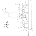
図1ないし図4は、本発明の実施例1による工作機械及びワーク加工方法を説明するための図である。 1 to 4 are views for explaining a machine tool and a workpiece machining method according to a first embodiment of the present invention.
図において、1はマシニングセンタ2に備えられたワーククランプ装置を示している。前記マシニングセンタ2は、主として、図2に示すように、工具Tが装着された主軸2a及び不図示のベッドに搭載されたテーブルをそれぞれX軸,Y軸,Z軸方向に相対移動させることによりワークWに所定の平面加工,溝加工,穴あけ加工等を行うように構成されている。
In the figure,
また図示していないが、前記マシニングセンタ2は、少なくとも加工領域を囲むように配設されたカバーを備えており、該カバーの機械正面側には作業用開口が形成され、該作業用開口は扉により開閉される。
Although not shown, the
前記ワーククランプ装置1は、前記テーブルに位置決め固定された矩形状の治具5と、該治具5上に配置固定され、前記ワークWが載置される3つの基準部材6と、該ワークWを基準部材6上に載置した状態でクランプする3つのクランプ機構7とを備えている。
The
また前記治具5には、前記ワークWを位置決めする2つの位置決めピン8,8が配設されている。この各位置決めピン8,8は、ワークWの大略対角線上に位置するよう配置されており、該ワークWに形成された位置決め孔(不図示)に挿入することで該ワークWのX軸方向及びY軸方向への移動を規制している。
The jig 5 is provided with two
前記3つの基準部材6は、三角形T1の頂点に位置するよう配置され、かつ前記ワークWの下面外縁部に対向するよう配置されている。
The three
前記各基準部材6の上面には、前記ワークWの下面に当接する平坦な基準面6aが共通の水平面上に位置するように形成されており、これによりワークWを3点で加工位置Aに支持するようになっている。
On the upper surface of each
前記各クランプ機構7は、前記治具5上に固定された支持部材10に揺動ピン11を介してクランプアーム12を揺動可能に支持し、該クランプアーム12の外端部12aに油圧により昇降駆動される駆動ロッド13を連結した構造を有する。前記各支持部材10は不図示の油圧室を有し、該油圧室は前記治具5内に設けられた油圧通路10aを介して油圧供給源14に連通接続されている。
Each
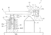
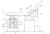
前記駆動ロッド13により前記クランプアーム12は、ワークWのクランプを解放するアンクランプ位置aと、ワークWを後述するリフトアップ位置Bに押圧するハーフクランプ位置bと、ワークWを加工位置Aに押圧するフルクランプ位置cとの間で揺動駆動される(図3,図4参照)。
With the
前記各クランプ機構7は、前記クランプアーム12の内端部12bがワークWを挟んで前記基準部材6の基準面6aに対向するよう配置されている。この内端部12bでワークWを押圧することにより該ワークWを基準部材6の基準面6aに固定するようになっている。
Each
そして本実施例のワーククランプ装置1は、前記ワークWを基準部材6の基準面6aより少し高所に設定された前記リフトアップ位置B及び該基準面6aに当接する前記加工位置Aに支持する3組の支持機構17、いわゆるナチュラルクランプ機構と、前記ワークWがリフトアップ位置Bにあるときに前記基準面6aに向かってクーラント又は高圧空気(洗浄用流体)を噴射供給する3組の洗浄機構18とを備えている。
The
前記各清浄機構18は、各基準部材6の基準面6aに指向するように配置された洗浄ノズル18aと、該洗浄ノズル18aにクーラントを供給するクーラント供給部25とを有する。このクーラント供給部25は、前記治具5内に設けられた洗浄通路18bを介して各洗浄ノズル18aに連通接続されている。
Each of the
前記3組の支持機構17は、三角形T2の頂点に位置し、かつ前記各基準部材6,6の間のワークWの下面外縁部に対向するように配置されている。
The three sets of
前記各支持機構17は、油圧室20aが形成されたシリンダ本体20と、該シリンダ本体20内に上下移動可能に配置されたプランジャ21と、前記シリンダ本体20内にプランジャ21を上方に付勢するよう配置されたプランジャバネ22と、前記プランジャ21に装着されたコレット23とを有する。
Each
前記各シリンダ本体20の油圧室20aは、前記治具5内に設けられた油圧供給通路20cを介して前記油圧供給源14に連通接続されている。この油圧室20aに油圧が供給されると、該油圧によりコレット23がプランジャ21を昇降不能に把持する。
The
前記プランジャ21は、シリンダ本体20の底壁に立設された支柱部20bに摺動可能に装着された円筒体21aに頭部21bを固定した構造を有し、該頭部21bと支柱部20bとの間に前記プランジャバネ22が配置されている。
The
前記プランジャバネ22は、シリンダ本体20の油圧室20aの油圧が開放されるとプランジャ21を前記リフトッアップ位置Bに上昇させ、該プランジャ21の頭部21bにワークWの重量が作用するとこの重量によりプランジャ21が下降する程度の軽いばね力に設定されている。
The
前記ワーククランプ装置1は、ワークWを基準部材6の基準面6aより高所に設定された前記リフトアップ位置Bに支持し、この状態で各基準面6aにクーラントを噴射した後、ワークWを各基準面6a上に載置するように構成されており、詳細には以下のように動作する。
The
ワーク加工が終了すると支持機構17の油圧が解放され、同時にクランプ機構7のクランプアーム12がクランプ位置cからアンクランプ位置aに回動する。これにより加工済ワークのクランプが開放される。
When the workpiece machining is completed, the hydraulic pressure of the
治具5から加工済みワークが搬出されると、プランジャバネ22によりプランジャ21が自動的にリフトアップ位置Bに上昇する。次いで油圧室20aに油圧が供給され、プランジャ21はコレット23によりリフトアップ位置Bに固定される。
When the processed workpiece is unloaded from the jig 5, the
次加工ワークが搬入されてプランジャ21上に載置され、クランプアーム12がアンクランプ位置aからハーフクランプ位置bに回動してワークWを押圧することにより、該ワークWはリフトアップ位置Bに保持される(図3参照)。これによりワークWと基準面6aとの間には数ミリ程度の隙間が形成される。
The next workpiece is loaded and placed on the
次いで、各洗浄ノズル18aから基準面6aに向かってクーラントが所定時間噴射される(図3の矢印参照)。この噴射されたクーラントにより基準面6aに付着した切り屑が洗い流される。
Next, coolant is sprayed from each
クーラントの供給が終了すると、支持機構17の油圧が解放され、プランジャ21がワークWの重量により下降し、該ワークWの下面が各基準面6aに当接する。
When the supply of the coolant is completed, the hydraulic pressure of the
次にクランプアーム12がハーフクランプ位置bからフルクランプ位置cに回動し、ワークWを加工位置Aにクランプする。この状態で支持機構17に再度油圧が供給され、プランジャ21が加工位置Aに固定される。これによりワークWは各基準部材6及び支持機構17により6点で支持されることとなる。
Next, the
上述の状態でワークに所定の平面加工,溝加工,穴あけ加工等が施される。ワーク加工中は、支持機構17に供給された油圧によってプランジャ21が加工位置Aに固定されているので、ワーク加工時の工具Tの押し付け荷重によるワークWのびびりや変形(図4の二点鎖線参照)が防止される。
In the above-described state, the workpiece is subjected to predetermined plane machining, grooving, drilling, and the like. During workpiece machining, since the
このように本実施例によれば、各基準部材6の基準面6aより高所に設定されたリフトアップ位置B及び該基準面6aに当接する加工位置AにワークWを支持する支持機構17と、ワークWがリフトアップ位置Bにあるときに前記基準面6aに向かってクーラントを吹き付ける洗浄機構18とを備えたので、ワークWを基準面6aに載置する直前に該基準面6aをクーラントにより洗浄することができ、切り屑を確実に除去することができる。その結果、ワークの傷付きや加工精度の悪化を防止できる。
Thus, according to the present embodiment, the lift mechanism B that is set higher than the
例えば、自動変速機のコントロールバルブでは、合わせ面を形成する平面加工及び油圧回路を形成する溝加工が行われる。この場合、合わせ面や油圧回路に切り屑による傷付きや加工精度の悪化が生じると、組み付けに必要な精度が得られなくなる。本実施例は、このような高い精度が要求されるワーク加工に好適である。 For example, in a control valve of an automatic transmission, planar processing for forming a mating surface and grooving for forming a hydraulic circuit are performed. In this case, if the mating surface or the hydraulic circuit is damaged by chips or the processing accuracy deteriorates, the accuracy required for assembly cannot be obtained. The present embodiment is suitable for workpiece machining that requires such high accuracy.
これにより人手による洗浄作業を不要にでき、生産性の悪化を防止できる。また作業用開口を開閉する扉を閉じた状態で洗浄を行うことができるので、機外にクーラント等が飛散することによる作業環境の悪化を防止できる。 This eliminates the need for manual cleaning work and prevents productivity from deteriorating. In addition, since the cleaning can be performed with the door that opens and closes the work opening being closed, it is possible to prevent the working environment from being deteriorated due to the scattering of coolant or the like outside the machine.
ワークWを基準部材6の3点のみで支持した場合、ワークWの基準部材6,6間部分やオーバーハング部分では工具Tからの荷重によりびびりや変形が生じ易い(図4の二点鎖線参照)。そこで、ワーク加工中は支持機構17のプランジャ21を加工位置Aに固定し、前述のワーク加工時の工具Tの押し付け荷重によるワークWのびびりや変形を防止し、加工精度を高めている。
When the workpiece W is supported by only three points of the
そして本実施例では、前記加工精度向上のために備えている支持機構17のプランジャ21のストロークを、ワークWをリフトアップ位置Bに支持可能のストロークに延長するだけで、ほとんどコストアップすることなく上述のワークWを基準面6aに載置する直前での該基準面6aのクーラントによる洗浄を実現できる。
In this embodiment, the stroke of the
また、コレット23に油圧を作用させることでプランジャ21をリフトアップ位置Bに固定する構造を採用したので、従来のばねを採用したものに比べてワークWをリフトアップ位置Bに確実に支持できる。また従来のばねを配置するスペースが不要となる分、装置を小型化できる。
In addition, since the structure in which the
1 ワーククランプ装置
2 マシニングセンタ(工作機械)
6 基準部材
6a 基準面
7 クランプ機構
17 支持機構
18 洗浄機構
A 加工位置
B リフトアップ位置
W ワーク
1 Work clamping
6
Claims (2)
前記支持機構は、前記ワークを、前記基準面より高所に設定されたリフトアップ位置及び前記ワークが基準面に当接する加工位置に支持可能に構成されており、
前記ワークがリフトアップ位置に支持されているときに前記基準面に向かって洗浄用流体を噴射する洗浄機構を備えた
ことを特徴とする工作機械。 A reference member having a reference surface on which the workpiece is placed, a clamping mechanism for clamping the workpiece placed on the reference surface against the reference surface, and a clamping portion of the workpiece placed on the reference surface A machine tool equipped with a support mechanism for supporting different parts,
The support mechanism is configured to be able to support the workpiece at a lift-up position set higher than the reference surface and a processing position where the workpiece contacts the reference surface,
A machine tool comprising a cleaning mechanism that ejects a cleaning fluid toward the reference surface when the workpiece is supported at a lift-up position.
前記支持機構によりワークを前記基準面より高所に設定されたリフトアップ位置に支持し、この状態で前記基準面に洗浄用流体を噴射供給し、
しかる後、前記支持機構によりワークを前記基準面に当接させると共に前記クランプ機構によりワークを前記基準面にクランプし、さらに前記支持機構により前記ワークのクランプ部位と異なる部位を支持した状態で該ワークを加工することを特徴とする工作機械のワーク加工方法。 A workpiece machining method for a machine tool, in which a workpiece is clamped on a reference surface by a clamping mechanism and the workpiece is machined in a state in which a portion different from the clamping portion of the workpiece is supported by a support mechanism,
The workpiece is supported by the support mechanism at a lift-up position set higher than the reference surface, and in this state, the cleaning fluid is jetted and supplied to the reference surface.
Thereafter, the workpiece is brought into contact with the reference surface by the support mechanism, the workpiece is clamped to the reference surface by the clamp mechanism, and the workpiece is supported by a portion different from the clamp portion of the workpiece by the support mechanism. A method for machining a workpiece of a machine tool, characterized by machining a workpiece.
Priority Applications (1)
| Application Number | Priority Date | Filing Date | Title |
|---|---|---|---|
| JP2011272652A JP2013123764A (en) | 2011-12-13 | 2011-12-13 | Machine tool and workpiece machining method of machine tool |
Applications Claiming Priority (1)
| Application Number | Priority Date | Filing Date | Title |
|---|---|---|---|
| JP2011272652A JP2013123764A (en) | 2011-12-13 | 2011-12-13 | Machine tool and workpiece machining method of machine tool |
Publications (1)
| Publication Number | Publication Date |
|---|---|
| JP2013123764A true JP2013123764A (en) | 2013-06-24 |
Family
ID=48775337
Family Applications (1)
| Application Number | Title | Priority Date | Filing Date |
|---|---|---|---|
| JP2011272652A Pending JP2013123764A (en) | 2011-12-13 | 2011-12-13 | Machine tool and workpiece machining method of machine tool |
Country Status (1)
| Country | Link |
|---|---|
| JP (1) | JP2013123764A (en) |
Cited By (1)
| Publication number | Priority date | Publication date | Assignee | Title |
|---|---|---|---|---|
| CN110153746A (en) * | 2019-05-28 | 2019-08-23 | 致兴国际钢结构(北京)有限公司 | A fixture platform for a steel structure connection plate and its use method |
-
2011
- 2011-12-13 JP JP2011272652A patent/JP2013123764A/en active Pending
Cited By (1)
| Publication number | Priority date | Publication date | Assignee | Title |
|---|---|---|---|---|
| CN110153746A (en) * | 2019-05-28 | 2019-08-23 | 致兴国际钢结构(北京)有限公司 | A fixture platform for a steel structure connection plate and its use method |
Similar Documents
| Publication | Publication Date | Title |
|---|---|---|
| JP4901884B2 (en) | Machine Tools | |
| JP5615129B2 (en) | Clamping device | |
| CN108406210A (en) | Clamp for welding | |
| CN110000518B (en) | Post-welding machining process and device for standard sections of elevators | |
| WO2013038568A1 (en) | Machine tool pallet changer, changing method and machine tool | |
| CN108907948B (en) | Automatic burr trimming workstation of engine cylinder lid robot | |
| KR102419511B1 (en) | Apparatus for changing a workpiece of a turning center | |
| KR20110067523A (en) | Automatic workpiece mounting device in vertical turning center | |
| KR20120063302A (en) | Long chip removal device for machine tools | |
| JP2013123764A (en) | Machine tool and workpiece machining method of machine tool | |
| JP3714516B2 (en) | Work unclamping structure of pallet for work conveyance. | |
| KR102545068B1 (en) | Deburring automation system for shaft | |
| CN217453843U (en) | Vacuum clamp | |
| CN118635776A (en) | A movable pin welding tool | |
| CN214922651U (en) | Metal workpiece processing equipment | |
| KR101680020B1 (en) | Plate processing machine | |
| JP7603841B2 (en) | Automatic workpiece fixing device | |
| JP4317502B2 (en) | Machine parts cleaning equipment | |
| JPWO2007132506A1 (en) | Machine tool equipment | |
| JP2019059005A (en) | Machine Tools | |
| JP7049805B2 (en) | Machine Tools | |
| JPH11170111A (en) | Deburring method and device for worked plate | |
| JP2012086327A (en) | Jig structure for machining | |
| JP2016120569A (en) | Processing device | |
| CN110802410A (en) | Combined type digit control machine tool |