JP2013137125A - Chemical heat storage device - Google Patents
Chemical heat storage device Download PDFInfo
- Publication number
- JP2013137125A JP2013137125A JP2011287336A JP2011287336A JP2013137125A JP 2013137125 A JP2013137125 A JP 2013137125A JP 2011287336 A JP2011287336 A JP 2011287336A JP 2011287336 A JP2011287336 A JP 2011287336A JP 2013137125 A JP2013137125 A JP 2013137125A
- Authority
- JP
- Japan
- Prior art keywords
- heat
- unit
- heat storage
- storage material
- heating
- Prior art date
- Legal status (The legal status is an assumption and is not a legal conclusion. Google has not performed a legal analysis and makes no representation as to the accuracy of the status listed.)
- Granted
Links
Images




Classifications
-
- Y—GENERAL TAGGING OF NEW TECHNOLOGICAL DEVELOPMENTS; GENERAL TAGGING OF CROSS-SECTIONAL TECHNOLOGIES SPANNING OVER SEVERAL SECTIONS OF THE IPC; TECHNICAL SUBJECTS COVERED BY FORMER USPC CROSS-REFERENCE ART COLLECTIONS [XRACs] AND DIGESTS
- Y02—TECHNOLOGIES OR APPLICATIONS FOR MITIGATION OR ADAPTATION AGAINST CLIMATE CHANGE
- Y02E—REDUCTION OF GREENHOUSE GAS [GHG] EMISSIONS, RELATED TO ENERGY GENERATION, TRANSMISSION OR DISTRIBUTION
- Y02E60/00—Enabling technologies; Technologies with a potential or indirect contribution to GHG emissions mitigation
- Y02E60/14—Thermal energy storage
Landscapes
- Air-Conditioning For Vehicles (AREA)
Abstract
【課題】化学蓄熱を利用した化学蓄熱装置であって、化学蓄熱材の加熱再生時におけるエネルギ効率を高め得る化学蓄熱装置を提供すること。
【解決手段】化学蓄熱装置(暖房装置1)は、反応部2、加熱部4および熱取出部6を有する。反応部2は、反応媒体と可逆的に反応して熱を発生させる化学蓄熱材Aを収容する蓄熱材収容部3と、蓄熱材収容部3に一体化されている発熱部34とを有する。加熱部4により発熱部34を誘導加熱することで、蓄熱材収容部3に収容されている反応後の反応生成物を加熱して反応生成物から反応媒体を分離させ、化学蓄熱材Aを再生する。熱取出部6は、反応部2に対して取り付けおよび取り外し可能に設けられており、化学蓄熱材Aが発生した熱を受熱するとともに受熱した熱を外部に放出する。
【選択図】図1The present invention provides a chemical heat storage device using chemical heat storage, which can improve energy efficiency during heating and regeneration of a chemical heat storage material.
A chemical heat storage device (heating device 1) includes a reaction unit 2, a heating unit 4, and a heat extraction unit 6. The reaction unit 2 includes a heat storage material storage unit 3 that stores the chemical heat storage material A that reversibly reacts with the reaction medium to generate heat, and a heat generation unit 34 that is integrated with the heat storage material storage unit 3. The heating unit 4 is induction-heated by the heating unit 4 to heat the reaction product after the reaction stored in the heat storage material storage unit 3 to separate the reaction medium from the reaction product, thereby regenerating the chemical heat storage material A. To do. The heat extraction unit 6 is provided so as to be attachable to and detachable from the reaction unit 2 and receives heat generated by the chemical heat storage material A and releases the received heat to the outside.
[Selection] Figure 1
Description
本発明は化学蓄熱装置に関し、特に電気自動車等の車両、建築構造物、屋外等において使用できる化学蓄熱装置に関する。 The present invention relates to a chemical heat storage device, and more particularly to a chemical heat storage device that can be used in vehicles such as electric vehicles, building structures, outdoors, and the like.
近年、車両、建築構造物、屋外等における暖房として、様々な暖房装置が考えられている。例えば、エンジンを搭載せずモータで走行する電気自動車では、エンジン駆動式の車両と異なり、エンジン冷却水の放熱を暖房熱として利用すること事が出来ない。このような場合に使用可能な暖房装置として、例えば特許文献1、2には、化学蓄熱を利用する方法(化学蓄熱装置)が開示されている。化学蓄熱材は反応媒体と反応して、熱を発生するとともに反応生成物を生成する。この反応は可逆反応であるため、化学蓄熱材は再生可能である。具体的には、反応媒体が水であれば、反応生成物を加熱し脱水反応させることで化学蓄熱材を再生できる。以下、必要に応じて、反応生成物を加熱し化学蓄熱材を再生することを、化学蓄熱材を加熱再生する、と称する。
In recent years, various heating devices have been considered as heating in vehicles, building structures, outdoors, and the like. For example, in an electric vehicle that runs on a motor without an engine, unlike an engine-driven vehicle, heat radiation from engine cooling water cannot be used as heating heat. As a heating device that can be used in such a case, for example,
特許文献1に紹介されている技術では、反応媒体と化学蓄熱材とを反応させる反応部の外部に電気ヒータを配設することで、反応部に収容されている反応生成物を加熱している。特許文献2に紹介されている技術では、反応部内に設けた流路に高温の流体を流通させることで、反応生成物を加熱している。
In the technique introduced in Patent Document 1, the reaction product accommodated in the reaction unit is heated by disposing an electric heater outside the reaction unit that causes the reaction medium and the chemical heat storage material to react. . In the technique introduced in
しかしながら特許文献1に紹介されている暖房装置では、ヒータを加熱することによって、ヒータと接合している反応部を間接的に加熱している。そして反応部内の反応生成物をさらに間接的に加熱している。このため、この暖房装置では、化学蓄熱材を加熱再生する際の伝熱ロスが大きく、化学蓄熱材を加熱再生する際の熱効率に劣る問題がある。また、ヒータの全面を反応部に接合しなければ更なる伝熱ロスが生じる問題もある。 However, in the heating apparatus introduced in Patent Document 1, the reaction portion joined to the heater is indirectly heated by heating the heater. And the reaction product in the reaction part is further heated indirectly. For this reason, in this heating device, there is a large heat transfer loss when heating and regenerating the chemical heat storage material, and there is a problem that the heat efficiency when heating and regenerating the chemical heat storage material is poor. Further, there is a problem that further heat transfer loss occurs unless the entire surface of the heater is joined to the reaction part.
また、特許文献2に紹介されている暖房装置では、化学蓄熱材を加熱再生する流体の温度が非常に高温である。このため、例えばこの種の暖房装置を電気自動車に搭載する場合には、流体の温度を十分に高くすることは非常に困難である。具体的には、特許文献2には、再生加熱時の流体の温度が424℃である旨が開示されている。
Moreover, in the heating apparatus introduced in
上述したように、特許文献1、2に例示される従来の暖房装置においては、化学蓄熱材を加熱再生させる機構が不十分であり、電力を過剰に消費する。このような事情により、電気自動車ばかりか、建築構造物、屋外等における暖房として、産業界では、電力の使用を低減できる暖房装置の開発が要請されている。更には、エンジン冷却用の冷却水を加熱する等、暖房以外の一般的な加熱用途にも適用可能な化学蓄熱装置の開発が要請されている。
As described above, in the conventional heating devices exemplified in
本発明は上記した実情に鑑みてなされたものであり、化学蓄熱を利用した化学蓄熱装置であって、化学蓄熱材の加熱再生時におけるエネルギ効率を高め得る化学蓄熱装置を提供することを課題とする。 This invention is made | formed in view of the above-mentioned situation, It is a chemical heat storage apparatus using chemical heat storage, Comprising: It aims at providing the chemical heat storage apparatus which can improve the energy efficiency at the time of the heating reproduction | regeneration of a chemical heat storage material. To do.
上記課題を解決する本発明の化学蓄熱装置は、(i)反応媒体と可逆的に反応して熱を発生するとともに反応生成物を生成する化学蓄熱材を収容する蓄熱材収容部と、該蓄熱材収容部に一体化されている発熱部と、該発熱部に一体化され該蓄熱材収容部の内部に延びる伝熱部と、を有する反応部と、(ii)該発熱部を誘導加熱することで該蓄熱材収容部に収容されている該反応生成物を加熱して該反応生成物から該反応媒体を分離させることにより該反応生成物を該化学蓄熱材として再生させる加熱部と、(iii)該反応部に対して取り付けおよび取り外し可能に設けられ、該化学蓄熱材が発生した熱を受熱するとともに受熱した熱を外部に放出する熱取出部と、を具備することを特徴とする。 The chemical heat storage device of the present invention that solves the above problems includes (i) a heat storage material storage unit that stores a chemical heat storage material that reversibly reacts with a reaction medium to generate heat and generates a reaction product, and the heat storage A reaction part having a heat generating part integrated with the material containing part, a heat transfer part integrated with the heat generating part and extending into the heat storage material containing part, and (ii) induction heating the heat generating part A heating unit that regenerates the reaction product as the chemical heat storage material by heating the reaction product stored in the heat storage material storage unit and separating the reaction medium from the reaction product; and iii) a heat extraction section that is detachably attached to the reaction section and receives heat generated by the chemical heat storage material and releases the received heat to the outside.
本発明の化学蓄熱装置は以下の要素(1)〜(5)の少なくとも一つを具備するのが好ましく、2以上を具備するのがより好ましい。
(1)前記伝熱部と前記発熱部とは一体成形されている。
(2)前記伝熱部は、前記発熱部に連続する伝熱基部と、該伝熱基部に連続する伝熱端部と、を有し、該伝熱端部は複数に分岐している。
(3)前記蓄熱材収容部は陥没形状をなす凹部を有し、前記発熱部の少なくとも一部は該凹部の壁面に形成され、前記加熱部の少なくとも一部は該凹部に挿入される凸状をなす。
(4)車両の室内を暖房するものである。
(5)車輪を回転駆動させる走行モータと、該走行モータを駆動させる電力を蓄電するとともに外部電源により充電可能なバッテリと、を有する車両に搭載されるものであり、該バッテリを該外部電源に接続して該外部電源から該バッテリを充電させるときに、前記加熱部は該外部電源から給電され前記発熱部を加熱して、前記反応生成物を化学蓄熱材として再生させる。
The chemical heat storage device of the present invention preferably comprises at least one of the following elements (1) to (5), more preferably 2 or more.
(1) The heat transfer section and the heat generating section are integrally formed.
(2) The heat transfer part has a heat transfer base part continuous with the heat generation part and a heat transfer end part continuous with the heat transfer base part, and the heat transfer end part is branched into a plurality.
(3) The heat storage material accommodating portion has a recessed portion having a depressed shape, at least a portion of the heat generating portion is formed on a wall surface of the recessed portion, and at least a portion of the heating portion is a convex shape inserted into the recessed portion. Make.
(4) The vehicle interior is heated.
(5) It is mounted on a vehicle having a travel motor that rotates and drives a wheel, and a battery that stores electric power for driving the travel motor and can be charged by an external power source. The battery is used as the external power source. When connecting and charging the battery from the external power source, the heating unit is supplied with power from the external power source to heat the heat generating unit and regenerate the reaction product as a chemical heat storage material.
本発明の化学蓄熱装置では、反応部の一部である発熱部を加熱部で誘導加熱する。つまり反応部自身が発熱する。このため、反応部を間接的に加熱する場合に比べて伝熱ロスに由来する熱損失を大幅に低減できる。また、本発明の化学蓄熱装置においては、発熱部に一体化されている伝熱部が、発熱部で生じた熱を反応部の内部に伝導する。このため化学蓄熱材を効率良く加熱再生できる。 In the chemical heat storage device of the present invention, the heat generating part which is a part of the reaction part is induction-heated by the heating part. That is, the reaction part itself generates heat. For this reason, compared with the case where a reaction part is heated indirectly, the heat loss resulting from a heat transfer loss can be reduced significantly. Moreover, in the chemical heat storage device of the present invention, the heat transfer part integrated with the heat generating part conducts heat generated in the heat generating part into the reaction part. For this reason, a chemical heat storage material can be efficiently heated and regenerated.
上記(1)を具備する本発明の化学蓄熱装置によると、発熱部と伝熱部とが一体成形されていることにより、発熱部と伝熱部との境界部分における伝熱ロスをなくす(または、ほぼなくす)ことができる。このため化学蓄熱材をさらに効率良く加熱再生できる。 According to the chemical heat storage device of the present invention having the above (1), the heat transfer loss at the boundary portion between the heat generating portion and the heat transfer portion is eliminated by integrally forming the heat generating portion and the heat transfer portion (or Can be almost eliminated). For this reason, a chemical heat storage material can be heated and regenerated more efficiently.
上記(2)を具備する本発明の化学蓄熱装置によると、伝熱部の表面積が大きくなるため、発熱部で生じた熱を反応部の内部に広範囲にわたって伝導できる。このため、化学蓄熱材をさらに効率良く加熱再生できる。 According to the chemical heat storage device of the present invention having the above (2), since the surface area of the heat transfer section is increased, the heat generated in the heat generating section can be conducted over a wide range inside the reaction section. For this reason, a chemical heat storage material can be heated and regenerated more efficiently.
上記(3)を具備する本発明の化学蓄熱装置によると、発熱部の表面積が大きくなるため、反応部全体を効率良く加熱でき、化学蓄熱材をさらに効率良く加熱再生できる。 According to the chemical heat storage device of the present invention having the above (3), since the surface area of the heat generating part is increased, the entire reaction part can be heated efficiently, and the chemical heat storage material can be heated and regenerated more efficiently.
上述したように、反応媒体と化学蓄熱材との反応で生じた熱は、自動車用の暖房に用いても良いし、建築構造物の室内または屋外等の暖房に用いても良い。更には、エンジン冷却用の冷却水を加熱したり物品を加熱する等、暖房以外の種々の用途に適用可能である。何れの場合にも、電気ヒータ等を使用する場合に比べて、暖房等の熱利用時に必要な電力が大きく低減するか、または、熱利用時に電力が不要になる。したがって本発明の化学蓄熱装置が上記(4)を備える場合には、車両走行時に暖房する際の電力の使用を低減または廃止でき、車両走行距離を延ばすのに有利となる。 As described above, the heat generated by the reaction between the reaction medium and the chemical heat storage material may be used for heating for automobiles or for heating indoors or outdoors in a building structure. Furthermore, the present invention can be applied to various uses other than heating such as heating cooling water for cooling an engine or heating an article. In any case, compared with the case where an electric heater or the like is used, the electric power required when using heat such as heating is greatly reduced, or no electric power is required when using heat. Therefore, when the chemical heat storage device of the present invention includes the above (4), it is possible to reduce or eliminate the use of electric power when heating the vehicle while traveling, which is advantageous for extending the vehicle travel distance.
さらに、車輪を回転駆動する走行モータと、走行モータを駆動する電力を蓄電するとともに外部電源により充電可能なバッテリと、を有する車両、つまり、所謂電気自動車またはハイブリッド自動車に本発明の化学蓄熱装置を搭載する場合には、化学蓄熱材の加熱再生にエンジンの廃熱を利用できないか、または、常には利用できない。このため、本発明の化学蓄熱装置はこれらの車両で使用される化学蓄熱装置として特に好ましく用いられる。勿論、これらの車両を暖房するための化学蓄熱装置としても好ましく用いられる。換言すると、本発明の化学蓄熱装置が上記(5)を備える場合には、車両走行時に暖房等の熱利用する際の電力の使用を低減または廃止でき、車両走行距離を延ばすのに有利となる。 Furthermore, the chemical heat storage device of the present invention is applied to a vehicle having a traveling motor that rotates the wheel and a battery that stores electric power for driving the traveling motor and can be charged by an external power source, that is, a so-called electric vehicle or hybrid vehicle. When installed, the waste heat of the engine cannot be used for heating regeneration of the chemical heat storage material, or cannot always be used. For this reason, the chemical heat storage device of the present invention is particularly preferably used as a chemical heat storage device used in these vehicles. Of course, it is also preferably used as a chemical heat storage device for heating these vehicles. In other words, when the chemical heat storage device of the present invention includes the above (5), it is possible to reduce or eliminate the use of electric power when using heat, such as heating, during vehicle travel, which is advantageous for extending the vehicle travel distance. .
本発明の化学蓄熱装置では、暖房等の加熱時には反応部に熱取出部が取り付けられる。この状態で、蓄熱材収容部に収容されている化学蓄熱材が反応媒体と可逆的に反応する。この反応により生じた熱は、熱取出部から取り出され、暖房熱等として使用される。このとき、化学蓄熱材は反応媒体と反応して反応生成物となる。 In the chemical heat storage device of the present invention, a heat extraction part is attached to the reaction part during heating such as heating. In this state, the chemical heat storage material housed in the heat storage material housing portion reacts reversibly with the reaction medium. The heat generated by this reaction is taken out from the heat extraction part and used as heating heat or the like. At this time, the chemical heat storage material reacts with the reaction medium to become a reaction product.
本発明の化学蓄熱装置には、蓄熱材収容部に流入する(および/または蓄熱材収容部から流出する)反応媒体の流量を規制するための流量規制部を設けても良い。具体的には、反応媒体を収容する媒体収容部と蓄熱材収容部との間を反応媒体が流通可能な連通路で連絡し、連通路に流量規制部を配設するのが好ましい。流量規制部としては、弁部、可変オリフィス、ポンプ等が挙げられる。弁部としては、オンオフ式の開閉バルブ、流量可変バルブが例示される。媒体収容部の圧力が化学蓄熱材収容部よりも高圧であるとき、流量規制部を開放すると、差圧に基づいて、反応媒体は連通路および流量規制部を介して媒体収容部から蓄熱材収容部に向かい、化学蓄熱材と反応して反応生成物を生成させつつ、反応熱を発生させる。 The chemical heat storage device of the present invention may be provided with a flow rate regulating unit for regulating the flow rate of the reaction medium flowing into the heat storage material accommodation unit (and / or flowing out of the heat storage material accommodation unit). Specifically, it is preferable to connect the medium storage unit that stores the reaction medium and the heat storage material storage unit through a communication path through which the reaction medium can flow, and to dispose a flow rate regulating unit in the communication path. Examples of the flow restricting portion include a valve portion, a variable orifice, a pump, and the like. Examples of the valve unit include an on / off type on-off valve and a flow rate variable valve. When the pressure of the medium storage unit is higher than that of the chemical heat storage material storage unit, if the flow rate control unit is opened, the reaction medium is stored from the medium storage unit via the communication path and the flow rate control unit based on the differential pressure. The reaction heat is generated while reacting with the chemical heat storage material to generate a reaction product.
反応生成物を化学蓄熱材として再生させるときには、蓄熱材収容部に収容されている反応生成物を、加熱手段で加熱する。具体的には反応部の一部である発熱部を誘導加熱する。そして発熱部からの熱伝導によって、反応部の他の一部である蓄熱材収容部に収容されている反応生成物を間接的に加熱する。これにより化学蓄熱材の反応生成物から反応媒体を分離させ、反応生成物を化学蓄熱材として再生させ、暖房に再度使用することができる。 When the reaction product is regenerated as a chemical heat storage material, the reaction product stored in the heat storage material storage unit is heated by a heating means. Specifically, the heat generating part which is a part of the reaction part is induction-heated. And the reaction product accommodated in the heat storage material accommodating part which is another part of the reaction part is indirectly heated by the heat conduction from the heat generating part. Thereby, the reaction medium can be separated from the reaction product of the chemical heat storage material, the reaction product can be regenerated as a chemical heat storage material, and used again for heating.
このとき、反応生成物から反応媒体が分離するため、蓄熱材収容部の内部の圧力は次第に増加する。そして、蓄熱材収容部の内部の圧力が媒体収容部の内部の圧力よりも高圧になっている時に流量規制部を開放すると、差圧に基づいて、蓄熱材収容部の反応媒体は連通路および流量規制部を介して媒体収容部に向かい、媒体収容部に収容される。 At this time, since the reaction medium is separated from the reaction product, the pressure inside the heat storage material accommodation portion gradually increases. Then, when the flow regulating part is opened when the pressure inside the heat storage material container is higher than the pressure inside the medium container, the reaction medium in the heat storage material container is connected to the communication path and the pressure difference based on the differential pressure. It goes to the medium accommodating part via the flow rate restricting part and is accommodated in the medium accommodating part.
なお、反応容器および/または熱取出手段は、持ち運び可能なポータブルタイプでも良いし、電気自動車等の車両、建築構造物、船舶、屋外等に固定的に据え付けられているタイプでも良い。例えば、本発明の化学蓄熱装置が車両に搭載される場合、熱取出し手段は車両に据え付けても良いし、車両に対して脱着可能であっても良い。反応容器もまた車両に据え付けても良いし、車両に対して脱着可能であっても良い。加熱手段は、車両に据え付けても良いが、車両に搭載しなくても良い。 The reaction vessel and / or the heat extraction means may be a portable portable type, or may be a type that is fixedly installed on a vehicle such as an electric vehicle, a building structure, a ship, or the outdoors. For example, when the chemical heat storage device of the present invention is mounted on a vehicle, the heat extraction means may be installed on the vehicle or may be removable from the vehicle. The reaction vessel may also be installed in the vehicle or may be removable from the vehicle. The heating means may be installed on the vehicle, but may not be mounted on the vehicle.
例えば熱取出手段を車両から取り外せば、住宅や屋外を暖房することもできる。また、外部加熱源によって発熱部を誘導加熱することで反応生成物を加熱再生することもできる。更には、反応容器を車両に対して脱着可能にし、加熱手段を車両の外部に配置することもできる。この場合、反応容器の一部である発熱部、蓄熱材収容部および媒体収容部もまた車両に対して脱着可能である。反応容器を車両から取り外し、車両の外部に配置した加熱手段によって発熱部を誘導加熱することで、蓄熱材収容部に収容されている反応生成物を加熱して、反応生成物から反応媒体を分離する。この場合、加熱手段は化学蓄熱装置専用でなくても良い。また、この場合の外部加熱源としては、車載電源以外の外部電源を用いることができる。 For example, if a heat extraction means is removed from a vehicle, a house or the outdoors can be heated. In addition, the reaction product can be heated and regenerated by inductively heating the heat generating portion with an external heating source. Furthermore, the reaction vessel can be attached to and detached from the vehicle, and the heating means can be arranged outside the vehicle. In this case, the heat generating part, the heat storage material accommodation part, and the medium accommodation part, which are part of the reaction container, are also detachable from the vehicle. The reaction container is removed from the vehicle, and the reaction product stored in the heat storage material storage unit is heated and the reaction medium is separated from the reaction product by induction heating of the heat generating unit by heating means arranged outside the vehicle. To do. In this case, the heating means may not be dedicated to the chemical heat storage device. In this case, an external power source other than the on-vehicle power source can be used as the external heating source.
化学蓄熱材および反応媒体は、互いに可逆的に反応して反応熱を発生させる。化学蓄熱材が反応した後の反応生成物が加熱されると、化学蓄熱材と反応媒体とは可逆的に分離される。このような化学蓄熱材としてはアルカリ土類金属(二価の金属)の化合物が挙げられる。アルカリ土類金属としては、カルシウム(Ca)、マグネシウム(Mg)、バリウム(Ba)が挙げられる。化合物としては水酸化物、酸化物、硫酸塩、硝酸塩、塩化物等が挙げられる。 The chemical heat storage material and the reaction medium react with each other reversibly to generate reaction heat. When the reaction product after the chemical heat storage material has reacted is heated, the chemical heat storage material and the reaction medium are reversibly separated. Examples of such chemical heat storage materials include alkaline earth metal (divalent metal) compounds. Examples of the alkaline earth metal include calcium (Ca), magnesium (Mg), and barium (Ba). Examples of the compound include hydroxide, oxide, sulfate, nitrate, chloride and the like.
下記の(I)〜(V)に例示する反応式に基づけば、化学蓄熱材Aとしては酸化カルシウム(CaO)、硫酸カルシウム(CaSO4)、酸化マグネシウム(MgO)、酸化バリウム(BaO)が挙げられる。反応媒体としては、価格、処理しやすさ等を考慮すると、液相状、気相状または気液共存状態の水が挙げられる。以下、これらの水を含めて水と称する。反応生成物としては、水酸化カルシウム(Ca(OH)2)、硫酸カルシウム1/2水和物(CaSO4・1/2H2O)、硫酸カルシウム2水和物(CaSO4・2H2O)、水酸化マグネシウム(Mg(OH)2)、水酸化バリウム(Ba(OH)2)が例示される。
(I)CaO+H2O→←Ca(OH)2
(II)CaSO4+1/2H2O→←CaSO4・1/2H2O
(III)CaSO4+2H2O→←CaSO4・2H2O
(IV)MgO+H2O→←Mg(OH)2
(V)BaO+H2O→←Ba(OH)2
上記した反応式として示すように、酸化カルシウム(CaO)、硫酸カルシウム(CaSO4)、酸化マグネシウム(MgO)、酸化バリウム(BaO)は、水(H2O)と可逆的に反応して熱を発生させる。反応生成物である水酸化カルシウム(Ca(OH)2)、硫酸カルシウム1/2水和物(CaSO4・1/2H2O)、硫酸カルシウム2水和物(CaSO4・2H2O)、水酸化マグネシウム(Mg(OH)2)、水酸化バリウム(Ba(OH)2)が、再生処理として加熱されると、反応生成物から水(H2O)を分離させつつ、元の出発材料である酸化カルシウム(CaO)、硫酸カルシウム(CaSO4)、酸化マグネシウム(MgO)、酸化バリウム(BaO)が可逆的に再生される。
Based on the reaction formulas exemplified in the following (I) to (V), examples of the chemical heat storage material A include calcium oxide (CaO), calcium sulfate (CaSO4), magnesium oxide (MgO), and barium oxide (BaO). . Examples of the reaction medium include water in a liquid phase, a gas phase, or a gas-liquid coexisting state in consideration of price, ease of processing, and the like. Hereinafter, these waters are referred to as water. The reaction products include calcium hydroxide (Ca (OH) 2 ), calcium sulfate hemihydrate (CaSO 4 · 1 / 2H 2 O), calcium sulfate dihydrate (CaSO 4 · 2H 2 O). And magnesium hydroxide (Mg (OH) 2 ) and barium hydroxide (Ba (OH) 2 ).
(I) CaO + H 2 O → ← Ca (OH) 2
(II) CaSO 4 + 1 / 2H 2 O → ← CaSO 4 · 1 / 2H 2 O
(III) CaSO 4 + 2H 2 O → ← CaSO 4 · 2H 2 O
(IV) MgO + H 2 O → ← Mg (OH) 2
(V) BaO + H 2 O → ← Ba (OH) 2
As shown in the above reaction formula, calcium oxide (CaO), calcium sulfate (CaSO 4 ), magnesium oxide (MgO), and barium oxide (BaO) react reversibly with water (H 2 O) to generate heat. generate. Calcium hydroxide (Ca (OH) 2 ), calcium sulfate hemihydrate (CaSO 4 · 1 / 2H 2 O), calcium sulfate dihydrate (CaSO 4 · 2H 2 O), which are reaction products, When magnesium hydroxide (Mg (OH) 2 ) and barium hydroxide (Ba (OH) 2 ) are heated as a regeneration treatment, water (H 2 O) is separated from the reaction product while the original starting material is used. Calcium oxide (CaO), calcium sulfate (CaSO 4 ), magnesium oxide (MgO), and barium oxide (BaO) are reversibly regenerated.
(実施形態1)
以下、具体例を挙げて本発明の化学蓄熱装置を説明する。図1に示すように、本発明の化学蓄熱装置における6方向を、便宜的に、上、下、左、右、前、後と呼ぶ。なお、後述する実施形態2以降における上、下、左、右、前、後もまた、図1に示す6方向と同じ方向である。
(Embodiment 1)
Hereinafter, the chemical heat storage device of the present invention will be described with specific examples. As shown in FIG. 1, the six directions in the chemical heat storage device of the present invention are called up, down, left, right, front, and back for convenience. In addition, the upper, lower, left, right, front, and rear in the second and later embodiments described later are also the same directions as the six directions shown in FIG.
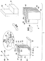
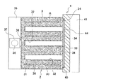
図1は実施形態1の化学蓄熱装置の概念図である。図2は実施形態1の化学蓄熱装置における反応部2および加熱部4を図1中前後左右方向に延びる平面で切断した様子を模式的に表す断面図である。なお、図2は反応部2に加熱部4が取り付けられている様子を表す。なお、実施形態1の化学蓄熱装置は暖房装置である。
FIG. 1 is a conceptual diagram of the chemical heat storage device of the first embodiment. 2 is a cross-sectional view schematically showing a state in which the
暖房装置1は、互いに分離可能な反応部2、加熱部4および熱取出部6を有する。この暖房装置1は、例えば、車載用、家庭用、業務用として使用できる。実施形態1の暖房装置において、反応部2、加熱部4および熱取出部6は何れも車両に搭載されている。
The heating device 1 includes a
反応部2は化学蓄熱材Aから熱を発生させるものであり、蓄熱材収容部3、水収容部35(反応媒体収容部)、連通路36、弁部37(流量規制部)を有する。蓄熱材収容部3は、反応媒体(水)と可逆的に反応して熱を発生させる粒状または粉末状の化学蓄熱材A(酸化カルシウム、CaO)を収容する収容室30をもつ容器31と、容器31に一体化されている発熱部34と、で構成されている。化学蓄熱材Aの粒子サイズは、反応性、反応媒体の通過性、コスト等を考慮して設定される。容器31は熱伝導性が良好な材料(例えばアルミニウム合金、銅合金、炭素鋼、合金鋼等の金属、熱伝導性が良いセラミックス)で形成されていることが好ましい。上記した(I)式に基づけば、酸化カルシウム(CaO)は水(H2O)と反応し、反応生成物として水酸化カルシウム(Ca(OH)2)を形成する。この場合、反応熱が発生し、蓄熱材収容部3が昇温する。
The
図1および図2に示すように、容器31は、凸状をなす複数の収容室30が離間配置されるとともにその一端部が連結されてなる櫛歯状をなす。互いに隣接する収容室30同士の間には凹部32が形成される。凹部32もまた複数形成されている。各収容室30の突出端部(図1中後側の端部)には、それぞれ、略板状をなす発熱部34が一体化されている。換言すると、容器31は図1中後側に開口を持つ箱状をなし、開口には発熱部34が嵌め込まれている。容器31と発熱部34とで、化学蓄熱材Aを収容する空間を区画形成している。
As shown in FIGS. 1 and 2, the
図2に示すように、各収容室30の内部には、略板状をなす伝熱部38が配置されている。各伝熱部38はそれぞれ各発熱部34に一体化され収容室30の内部に延びている。発熱部34および伝熱部38は同材(鉄)からなり、一体成形されている。なお、発熱部34は誘導加熱可能な材料からなれば良い。例えば、誘導加熱可能な材料とは、鉄等の磁性体および/またはアルミニウム、銅、ステンレスルチール等の誘導加熱可能な非磁性体を含む材料を指す。熱効率を考慮すると、発熱部34の材料は磁性体であるのがより好ましい。また、発熱部34は後述する加熱部4と広い面積で接触するのが好ましい。さらに、熱膨張による変形等を考慮すると、発熱部34は肉厚略一定の平板状をなすのが好ましい。伝熱部38は熱伝導率の高い材料からなるのが好ましい。発熱部34と伝熱部38とは一体であれば良く、同材であっても良く、異材であっても良い。また一体に成形しても良いし別体で成形し一体化しても良い。しかし発熱部34と伝熱部38との間での熱損失を考慮すると、発熱部34と伝熱部38は一体成形するのが好ましく、同材からなるのが好ましい。
As shown in FIG. 2, a
凹部32は陥没形状をなす。さらに蓄熱材収容部3は、熱取出部6および/または加熱部4の支持性を高めるためのサポート部33を有する。サポート部33は熱取出部6および/または加熱部4の表面と係合可能である。なお、場合によっては、サポート部33を廃止しても良い。
The
水収容部35は、蓄熱材収容部3に接続された状態で配置されている。水収容部35は、水(反応媒体)を予め収容しており、更に、再生時において蓄熱材収容部3に収容されている化学蓄熱材Aの反応生成物から分離された水(反応媒体)を収容する。連通路36は、蓄熱材収容部3と水収容部35とを連通させることにより、蓄熱材収容部3と水収容部35との間において水を移動させる。弁部37は連通路36を開閉させる。
The
図1に示すように、熱取出部6は、反応部2の凹部32に対して取り付けおよび取り外し可能に設けられている。具体的には、熱取出部6は、凹部32と相補的な突起状をなし凹部に対して挿入可能かつ伝熱可能である受熱部60と、受熱部60に熱的に連絡する放熱フィンで形成された放熱部62とを有する。受熱部60が凹部32に脱着可能に挿入されて、熱取出し部6が反応部2に取り付けられると、熱取出部6が反応部2の凹部32に取り付けられ、熱取出部6および反応部2が一体となる。このように熱取出部6が反応部2に取り付けられているとき、受熱部60は、蓄熱材収容部3の化学蓄熱材Aが発生した反応熱を受熱する。放熱部62は、受熱部60が受熱した熱を外部に暖房熱として放出させる。このため熱取出部6は暖房機器として機能できる。なお、受熱部60および放熱部62は、熱伝導性に優れる材料(例えばアルミニウム合金、銅合金、炭素鋼、合金鋼等の金属)で形成されていることが好ましい。受熱部60および放熱部62の熱接触面積は大きい方が好ましい。
As shown in FIG. 1, the
蓄熱材収容部3に収容されている化学蓄熱材A(酸化カルシウム、CaO)が反応を終えて反応生成物となると、暖房機能は低下する。暖房機能が低下したら、熱取出し部6を反応部2から取り外し、加熱部4を反応部2に取り付ける。熱取出し部6を反応部2に対して図1中上から下に向けてスライドさせれば、熱取出部6を反応部2に取り付けることができる。また、熱取出部6を反応部2に対して下から上に向けてスライドさせれば、熱取出部6を反応部2から取り外すことができる。加熱部4を反応部2に取り付けるまたは取り外す場合にも同様である。
When the chemical heat storage material A (calcium oxide, CaO) stored in the heat storage
加熱部4は、IHヒータ40と、IHヒータ40に一体化されているスペーサ部41とを持つ。スペーサ部41は、加熱部4を反応部2に取り付けたときに、反応部2のサポート部33と係合する部分である。加熱部4を反応部2に取り付けるときには、加熱部4を反応部2に対して図1中上から下に向けてスライドさせれば良い。加熱部4を反応部2から取り外す場合には、加熱部4を反応部2に対して図1中下から上に向けてスライドさせれば良い。
The
実施形態1の暖房装置において、加熱部のIHヒータ40に給電する電源(図略)は車両に搭載されている。給電を受けたIHヒータ40は、コイル44を発熱部34側(つまり図1中前側)に向け、蓄熱材収容部3に一体化されている発熱部34を誘導加熱する。発熱部34で生じた熱は、発熱部34に一体化されている伝熱部38および容器31に伝熱し、蓄熱材収容部3が加熱される。蓄熱材収容部3に収容されている化学蓄熱材Aの反応生成物(水酸化カルシウム、Ca(OH)2)は蓄熱材収容部3からの伝熱により加熱される。反応生成物を加熱すると、反応生成物の吸熱反応により、反応生成物から水(H2O)が分離し、反応生成物が元の化学蓄熱材A(酸化カルシウム、CaO)に再生する。再生した化学蓄熱材A(CaO)を再び水(H2O)と反応させれば、暖房熱となる反応熱を生成させつつ反応生成物(Ca(OH)2)となる。なお、IHヒータ40は、蓄熱材収容部3および/または発熱部34と別体であっても良いし、固着などして一体化しても良い。スペーサ部41は省略可能である。
In the heating device according to the first embodiment, a power source (not shown) for supplying power to the
本実施形態によれば、水収容部35、蓄熱材収容部3および連通路36の内部は、基本的には減圧雰囲気とされている。よって、水収容部35に収容されている水(反応媒体)の一部または大部分は、蒸発して水蒸気となっている。低温環境においても水収容部35には多量の水蒸気が収容されている。
According to the present embodiment, the interior of the
暖房前では、水収容部35に収容されている水の蒸発が進行しているため、水収容部35の内部圧力Pwが蓄熱材収容部3の内部圧力Pcよりも高くされている。この状態で、制御装置または手動により弁部37が開放されると、差圧に基づいて、水収容部35の水蒸気(水)は、連通路36および弁部37を介して蓄熱材収容部3に移動し、蓄熱材収容部3の化学蓄熱材Aと反応して反応熱を暖房熱として生成させる。暖房時間が継続し水収容部35に収容されていたかなりの流量の水蒸気(水)が連通路36を介して蓄熱材収容部3に移動すると、水収容部35の内部圧力Pwが次第に低下し、差圧が低下すると共に、蓄熱材収容部3の化学蓄熱材Aの大部分が反応生成物とされる。化学蓄熱材Aの大部分が反応生成物とされると、反応熱が低下して暖房能力が低下するため、反応生成物を再生させることが好ましい。
Before the heating, the evaporation of the water stored in the
反応生成物を再生させるときには、IHヒータ40で発熱部34を誘導加熱することにより蓄熱材収容部3内の反応生成物を加熱する。すると、蓄熱材収容部3に収容されている反応生成物が水を水蒸気として放出するため、蓄熱材収容部3の内部圧力Pcが次第に高くなり、水収容部35の内部圧力Pwよりも高くなる。この状態で弁部37が開放されると、蓄熱材収容部3に溜まっている水蒸気(水)は、差圧に基づいて、連通路36および弁部37を介して水収容部35に移動し、水収容部35で冷却されて凝縮されて液相状の凝縮水となる。このように水収容部35は凝縮器として機能できる。
When the reaction product is regenerated, the reaction product in the heat storage
弁部37の構造は特に限定されるものではない。弁部37はオンオフする開閉弁でも良い。この場合、制御装置は弁部37を連続的に開放させてもよいし、断続的に開放させても良い。断続的に開放される場合、弁部37の開放時間(オン時間)を調整すれば、水収容部35から蓄熱材収容部3に向かう単位時間あたりの水蒸気の流量を調整できるため、暖房装置1の暖房能力を調整できる。あるいは、弁部37は、連通路36を流れる単位時間当たりの水蒸気の流量を可変にできる可変弁でも良い。この場合、流量を調整すれば、水収容部35から蓄熱材収容部3に向かう単位時間あたりの水蒸気の流量を調整できるため、暖房装置1の暖房能力を調整できる。
The structure of the
本実施形態によれば、図1に示すように、蓄熱材収容部3に形成されている凹部32は、図1中上下方向に延設され互いに対向する伝熱面32cを有するスライド溝状をなす。相手側である受熱部60は、図1中上下方向に延設され互いに対向する伝熱面60cを有する凸状をなす。このため、反応部2の凹部32に対して熱取出部6の受熱部60を図1中上下方向に沿って嵌合させつつ相対的にスライドさせる簡単な操作で、反応部2に対して熱取出部6を取り付けることができる。伝熱面32c、60c同士は接触することが好ましいが、場合によっては、伝熱できる限り、微小隙間が形成されていても良い。また、分離させるときにおいても、反応部2の凹部32に対して熱取出部6の受熱部60を図1中上方向にスライドさせる簡単な操作で嵌合を解除させ、反応部2および熱取出部6を互いに分離させることができる。なお、凹部32の形状はこれに限定されず、例えば図1中左右方向に延びるスライド溝状であっても良い。この場合、反応部2の凹部32に対して熱取出部6の受熱部60を横方向に沿って嵌合させつつ相対的にスライドさせる簡単な操作で、反応部2に対して熱取出部6を取り付けることができる。反応部2と加熱部4との取り付けおよび取り外しに関しても同様である。
According to the present embodiment, as shown in FIG. 1, the
更に図1に示すように、水収容部35、連通路36および弁部37は、反応部2のうち凹部32と反対側の側部3sに設けられている。このため、反応部2と熱取出部6とを互いに脱着する際、および、反応部2と加熱部4とを互いに脱着する際にも、これらと干渉し難い。但し、水収容部35、連通路36および弁部37のうちの少なくとも一つを、熱取出部6と干渉しないように、反応部2の下面側に設けても良い。
Further, as shown in FIG. 1, the
なお、実施形態1の暖房装置においては、反応後の化学蓄熱材Aを再生させるときに、反応部2から熱取出部6を取り外し、反応部2と熱取出部6とを互いに分離させる。この状態で、IHヒータ4により発熱部34を誘導加熱すれば、IHヒータ4の熱が熱取出部60に奪われることが抑制される。従って、IHヒータ4の熱が反応部2の蓄熱材収容部3に効率良く伝達される。ひいては、反応部2の蓄熱材収容部3に収容されている反応後の反応生成物を効率良く加熱させ、化学蓄熱材Aとして再生させることができる。この結果、本実施形態によれば、反応生成物から化学蓄熱材Aを再生させる再生効率を高めることができる。
In addition, in the heating apparatus of Embodiment 1, when regenerating the chemical heat storage material A after reaction, the
実施形態1では、化学蓄熱材として酸化カルシウム(CaO)を採用しているが、これに限らず、例えば硫酸カルシウム(CaSO4)、酸化マグネシウム(MgO)、酸化バリウム(BaO)を採用しても良い。 In the first embodiment, calcium oxide (CaO) is employed as the chemical heat storage material. However, the present invention is not limited to this. For example, calcium sulfate (CaSO 4 ), magnesium oxide (MgO), and barium oxide (BaO) may be employed. good.
また、実施形態1における熱取出部6は、凹部32に対して伝熱可能に取り付けられるブロック状の受熱部60と、受熱部60に伝熱可能に繋げられた所謂放熱フィン状の放熱部62とを有するが、放熱部は、水や空気等の熱媒体を通過させる配管で形成しても良く、要するに暖房熱を放出できるものであれば良い。
Moreover, the
実施形態1では、流量規制部として弁部37を設けたが、これにかえて可変オリフィスやポンプを用いても良い。例えば、弁部37として流量可変バルブを用い、暖房時には、水収容部35の水蒸気(水)が、連通路36および弁部37を介して蓄熱材収容部3に移動するようにし、蓄熱材収容部3の化学蓄熱材Aと反応して反応熱を暖房熱として生成させる。このとき弁部37の流路断面積を調整することで、暖房出力を調整できる。更に、再生時には、弁部37の流路断面積を最大値とすることが好ましい。この場合、IHヒータ4による加熱を受け反応生成物から脱離した水蒸気を、蓄熱材収容部3から迅速に水収容部35に戻すことができる。このため反応生成物からの水蒸気脱離が促進され、再生時間の短縮に貢献できる。
In the first embodiment, the
また、水収容部35の内部圧力Pwと、蓄熱材収容部3の内部圧力Pcを検知することで、水蒸気の移動方向を把握し、暖房可能であるか否かを判断することも可能である。つまり、水収容部35、蓄熱材収容部3および連通路36の内部は、基本的には減圧雰囲気とされている。よって、水収容部35に収容されている水の一部または大部分は水蒸気である。暖房前においては、水収容部35および蓄熱材収容部3は基本的に同じ温度であると考えられる。この場合、通常の状態では、減圧雰囲気の水収容部35に収容されている水の蒸発が進行しているため、弁部37が閉鎖している状態では、水収容部35の内部圧力Pwは蓄熱材収容部3の内部圧力Pcよりも高い。この状態で弁部37が開放されると、差圧に基づいて、水収容部35の水蒸気(水)は連通路36および弁部37を介して蓄熱材収容部3に移動し、蓄熱材収容部3の化学蓄熱材Aと反応する。
Further, by detecting the internal pressure Pw of the
水収容部35の内部圧力Pwが蓄熱材収容部3の内部圧力Pcよりも所定値以上高ければ、弁部37の開放により、水収容部35の水蒸気を蓄熱材収容部3に良好に移動させて化学蓄熱材Aと反応させ、反応熱を暖房熱として発生させることができる。逆に、内部圧力Pwと内部圧力Pcとの差圧がなければ、弁部37が開放していたとしても、水収容部35の水蒸気を蓄熱材収容部3に移動させることができず、暖房熱は基本的には発生しない。したがって、内部圧力Pc、Pwを検知することで、水蒸気の移動方向を把握でき、暖房装置1が暖房可能な状態であるか否かを判断できる。
If the internal pressure Pw of the
また、水収容部35の内部温度は、基本的には、水収容部35において生成される水蒸気量に影響を与え、水収容部35の水蒸気圧として換算することができる。蓄熱材収容部3の内部温度は、蓄熱材収容部3において生成される水蒸気量に影響を与え、基本的には、蓄熱材収容部3の水蒸気圧として換算することができる。つまり、水収容部35および蓄熱材収容部3の内部温度を検知することによっても、水収容部35の内部圧力Pwと蓄熱材収容部3の内部圧力Pcとの高低および差圧を推定できる。より具体的には、図1に示すように、水収容部35の内部温度または内部圧力を検知する第1センサ91の検知信号、蓄熱材収容部3の内部温度または内部圧力を検知する第2センサ92の検知信号、に基づき、第1センサ91および第2センサ92に接続された制御装置93により、水収容部35の内部圧力Pwと蓄熱材収容部3の内部圧力Pcとの高低および差圧を演算し、演算結果に応じてユーザーに暖房の可否を告知することもできる。
The internal temperature of the
この暖房装置は、例えば車両や室内、屋外等に単に載置するだけでも良いし、或いは送風装置の下流側に取り付けても良い。すなわち、送風装置が吹き出す冷風を実施形態1の暖房装置に通過させ、温風として取り出しても良い。 This heating device may be simply placed, for example, in a vehicle, indoors, outdoors, or may be attached to the downstream side of the blower. That is, the cool air blown out by the blower may be passed through the heating device of Embodiment 1 and taken out as hot air.
(実施形態2)
図3は実施形態2の暖房装置の概念図であり、具体的には、取付前の反応部2および加熱部4と、取付後(再生時)の反応部2および加熱部4と、を模式的に表す。図4は実施形態2の暖房装置における反応部2および加熱部4を、図2と同位置で切断した様子を模式的に表す断面図である。なお、図4は反応部2に加熱部4が取り付けられている様子を表す。本実施形態は前記した実施形態1と基本的に同様の構成および同様の作用効果を有する。熱取出部は図示しないが、実施形態1の熱取出部6と同じものである。以下、相違する部分を中心として説明する。
(Embodiment 2)
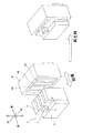
FIG. 3 is a conceptual diagram of the heating apparatus according to the second embodiment. Specifically, the
図3に示すように、実施形態2における加熱部4は、実施形態1における熱取出部6の受熱部60と略同形状の伝熱凸部42を複数持つ。伝熱凸部42はIHヒータ40におけるコイル44側の表面から図3中前方に突出している。伝熱凸部42は熱伝導性に優れる材料からなれば良く、伝熱部38ならびに実施形態1にて説明した受熱部60および放熱部62と同様の材料で構成できる。実施形態2における伝熱凸部42は鉄製である。
As shown in FIG. 3, the
図4に示すように、実施形態2における伝熱部38は発熱部34に一体化されている伝熱基部38aと伝熱基部38aから延びる伝熱端部38bとを持ち、伝熱端部38bは樹状に分岐している。蓄熱材収容部3の凹部32の壁面は、加熱部4および伝熱部38と同材(鉄)からなり、加熱部4および伝熱部38と一体に成形されている。換言すると、伝熱部38の伝熱端部38bは凹部32の壁面を介して伝熱凸部42と熱的に連絡している。
As shown in FIG. 4, the
加熱部4を反応部2に取り付けると、加熱部4の伝熱凸部42は蓄熱材収容部3の凹部32に挿入される。この状態で加熱部4のIHヒータ40に給電すると、IHヒータ40は発熱部34および伝熱凸部42を誘導加熱する。発熱部34の熱は伝熱部38に熱伝導し、蓄熱材収容部3の内部に収容されている化学蓄熱材Aを加熱する。なお、図4に示すように実施形態2における伝熱端部38bは樹状に分岐しているため、発熱部34から伝熱部38に伝導した熱は蓄熱材収容部3の内部全体に略均一に伝導する。よって、化学蓄熱材Aの加熱むらを低減できる。
When the
一方、加熱部4の伝熱凸部42のなかでIHヒータ40に隣接する部分もまた、IHヒータ40により誘導加熱される。この熱は伝熱凸部42全体に伝導し、伝熱凸部42と熱的に連絡する伝熱部38にも伝導する。このことによっても、実施形態2における蓄熱材収容部3の内部は略均一に加熱され、化学蓄熱材Aの加熱むらをさらに低減できる。
On the other hand, the portion adjacent to the
また、蓄熱材収容部3に一体化されている発熱部4を直接誘導加熱することで、化学蓄熱材Aを再生する際の熱損失を低減できる。さらに、発熱部4と伝熱部38とは一体成形されてなるため、発熱部4から伝熱部38に伝熱する際の熱損失を低減できる。これらの協働により、実施形態3の暖房装置によると、化学蓄熱材Aをより効率良く加熱再生できる。
Moreover, the heat loss at the time of reproducing | regenerating the chemical thermal storage material A can be reduced by carrying out the induction heating of the heat-generating
(実施形態3)
図5は実施形態3の暖房装置における反応部2および加熱部4を、図2と同位置で切断した様子を模式的に表す断面図である。なお、図5は反応部2に加熱部4が取り付けられている様子を表す。本実施形態は前記した実施形態1と基本的に同様の構成および同様の作用効果を有する。熱取出部は図示しないが、実施形態1の熱取出部6と同じものである。以下、相違する部分を中心として説明する。
(Embodiment 3)
FIG. 5 is a cross-sectional view schematically illustrating a state in which the
図5に示すように、実施形態3における加熱部4は、実施形態1、2の加熱部4におけるIHヒータ40と同位置に配設されているコイル44aと、3つの伝熱凸部42にそれぞれ1つずつ配設されている3つのコイル44bと、を持つ。つまり、実施形態3における加熱部4は実施形態1、2におけるIHヒータ40と略同形状の第1のIHヒータ40aと、3つの伝熱凸部42にそれぞれ一体化されている第2のIHヒータ40bと、を持つ。具体的には、各IHヒータ40bは、コイル44bを伝熱凸部42の右側に向けている。凹部32のなかで伝熱凸部42の右側に隣接する壁面32aは鉄製であり、発熱部34および伝熱部38と一体成形されている。つまり、壁面32aは伝熱端部38bと一体化され、発熱部34および伝熱部38と熱的に連絡している。そして壁面32aは、IHヒータ40bにより誘導加熱されて発熱する第2の発熱部として機能する。換言すると、実施形態3の暖房装置は、発熱部34および加熱部4からなる誘導加熱機構を四対持つ。伝熱端部38bは第2の発熱部(壁面32a)に一体化されている。
As shown in FIG. 5, the
実施形態3の暖房装置は、実施形態1、2の暖房装置と同様に、発熱部4を直接誘導加熱したこと、および、発熱部4と伝熱部38とを一体成形したことで、化学蓄熱材Aを再生する際の熱損失を低減できる。また、発熱部34および加熱部4からなる誘導加熱機構を四対設けたことで、蓄熱材収容部3に一度に大きな熱エネルギを与え得る。さらに伝熱部38および伝熱凸部42により蓄熱材収容部3の内部全体を密に熱的に連絡したことで、蓄熱材収容部3の内部全体を略均一に加熱することができる。これらの協働により、実施形態3の暖房装置によると、化学蓄熱材Aをより効率良く加熱再生できる。
The heating device of the third embodiment is similar to the heating devices of the first and second embodiments, in that the
(実施形態4)
図6は実施形態4の暖房装置の概念図であり、具体的には、取付前の反応部2および加熱部4と、取付後(再生時)の反応部2および加熱部4と、を模式的に表す。図7は実施形態4の暖房装置における反応部2および加熱部4を、図2と同位置で切断した様子を模式的に表す断面図である。なお、図7は反応部2に加熱部4が取り付けられている様子を表す。本実施形態は前記した実施形態1と基本的に同様の構成および同様の作用効果を有する。熱取出部は図示しないが、実施形態1の熱取出部6と同じものである。以下、相違する部分を中心として説明する。
(Embodiment 4)
FIG. 6 is a conceptual diagram of the heating device according to the fourth embodiment. Specifically, the
図6に示すように、実施形態4における加熱部4は、図6中前方に開口する箱状をなす。図7に示すように、加熱部4の底面45a、左壁面45bおよび右壁面45cには、それぞれ、コイル44(44a〜44c)が箱の内部を向くように取り付けられている。加熱部4の底面45aは第1のIHヒータ40aを構成している。加熱部4の左壁面45bおよび右壁面45cは、それぞれ、第2のIHヒータ40b、40cを構成している。容器31のなかで加熱部4の底面45aに対面する部分(つまり容器31の後端面)には、実施例形態1〜3と同様に発熱部34が一体化されている。容器31のなかで第2のIHヒータ40b、40cに対面する壁面(つまり容器31の右壁面31aおよび左壁面31b)は鉄製であり、発熱部34および伝熱部38と一体成形されている。つまり、壁面31a、31bは伝熱端部38bと一体化され、発熱部34および伝熱部38と熱的に連絡している。そして壁面31a、31bは、第2のIHヒータ40b、40cにより誘導加熱されて発熱する第2の発熱部として機能する。換言すると、実施形態4の暖房装置は、発熱部34および加熱部4からなる誘導加熱機構を三対持つ。
As shown in FIG. 6, the
実施形態4の暖房装置は、実施形態1〜3の暖房装置と同様に、発熱部4を直接誘導加熱したこと、および、発熱部4と伝熱部38とを一体成形したことで、化学蓄熱材Aを再生する際の熱損失を低減できる。さらに伝熱部38により蓄熱材収容部3の内部全体を略均一に加熱することができる。このため実施形態4の暖房装置によると、化学蓄熱材Aをより効率良く加熱再生できる。さらに、加熱部4を箱状にしたことで、加熱部4を複雑な形状にすることなく、蓄熱材収容部3を複数箇所から加熱でき、化学蓄熱材Aを効率良く再生できる。
The heating device of the fourth embodiment is similar to the heating devices of the first to third embodiments, in that the
(実施形態5)
図8は実施形態5の暖房装置の概念図であり、具体的には、取付前の反応部2および加熱部4と、取付後(再生時)の反応部2および加熱部4と、を模式的に表す。図9は実施形態5の暖房装置における反応部2および加熱部4を、図2と同位置で切断した様子を模式的に表す断面図である。なお、図9は反応部2に加熱部4が取り付けられている様子を表す。本実施形態は前記した実施形態1と基本的に同様の構成および同様の作用効果を有する。熱取出部は図示しないが、実施形態1の熱取出部6と同じものである。以下、相違する部分を中心として説明する。
(Embodiment 5)
FIG. 8 is a conceptual diagram of the heating apparatus according to the fifth embodiment. Specifically, the
図8に示すように、実施形態5における加熱部4は、実施形態4における加熱部4と同様に図8中前方に開口する箱状をなし、さらに、箱の内部に3つの伝熱凸部42が立設されたものである。各伝熱凸部42は実施形態2における伝熱凸部42と略同形状であり、IHヒータ40aの表面に一体化されている。したがって、伝熱凸部42の後端部は発熱部34とともにIHヒータ40aにより誘導加熱される。
As shown in FIG. 8, the
図9に示すように、箱の底面45a、左壁面45bおよび右壁面45cには、実施形態4と同様にコイル44(44a〜44c)がそれぞれ取り付けられている。加熱部4の底面45aは第1のIHヒータ40aを構成し、加熱部4の左壁面45bおよび右壁面45cは、それぞれ、第2のIHヒータ40b、40cを構成している。容器31の後端面には発熱部34が一体化され、容器31の壁面全面は伝熱部38および発熱部34と一体成形されている。つまり、容器31全体が伝熱端部38bと一体化され、発熱部34および伝熱部38と熱的に連絡している。容器31は加熱部4および伝熱部38と同じ鉄製である。なお、実施形態5の暖房装置は、実施形態4の暖房装置と同様に、発熱部34および加熱部4からなる誘導加熱機構を三対持つ。
As shown in FIG. 9, coils 44 (44a to 44c) are respectively attached to the
実施形態5の暖房装置は、実施形態1〜4の暖房装置と同様に、発熱部4を直接誘導加熱したこと、および、発熱部4と伝熱部38とを一体成形したことで、化学蓄熱材Aを再生する際の熱損失を低減できる。さらに伝熱部38および伝熱凸部42により蓄熱材収容部3の内部全体を密に熱的に連絡したことで、蓄熱材収容部3の内部全体を略均一に加熱できる。これらの協働により、実施形態5の暖房装置によると、化学蓄熱材Aをより効率良く加熱再生できる。
The heating device of the fifth embodiment is similar to the heating devices of the first to fourth embodiments, in that the
(実施形態6)
図10は実施形態6の暖房装置における反応部2および加熱部4を、図2と同位置で切断した様子を模式的に表す断面図である。なお、図10は反応部2に加熱部4が取り付けられている様子を表す。本実施形態は前記した実施形態1と基本的に同様の構成および同様の作用効果を有する。熱取出部は図示しないが、実施形態1の熱取出部6と同じものである。以下、相違する部分を中心として説明する。
(Embodiment 6)
FIG. 10 is a cross-sectional view schematically showing a state in which the
図10に示すように、実施形態6の暖房装置における伝熱部38は管状をなし、水を蓄熱材収容部3に流通させるための給排管としても機能する。伝熱部38は蓄熱材収容部3の内部全体に分布している。このため、伝熱部38を給排管として利用することで、水蒸気等の水を収容室30の化学蓄熱材A(CaO)にまんべんなく接触させて反応させ、暖房熱を生成できる。伝熱部38の周壁には、所定間隔で開口38cが形成されている。開口38cは水の出入り口となる。伝熱部38の一端部である伝熱基部38aは発熱部34と一体成形されている。伝熱部38の他端部である給排接続部38dは、中空状の集合室39に接続されている。集合室39は連通路36に接続され、さらに弁部37を介して水収容部35に接続されている。
As shown in FIG. 10, the
再生時には、伝熱部38は収容室30の反応生成物(Ca(OH)2)を加熱して水を分離させ、反応生成物(Ca(OH)2)を化学蓄熱材A(CaO)として再生させることができる。反応生成物から分離された水蒸気等の水は、伝熱部38の開口38c、内部38e、集合室39、連通路36a、弁部37、連通路36bを介して水収容部35に戻る。なお、反応時(暖房時)において、水はこの経路を逆に流通し水収容部35から蓄熱材収容部3に到達し、化学蓄熱材Aと反応する。
At the time of regeneration, the
(実施形態7)
図11は実施形態7の概念図を示す。本実施形態は前記した実施形態1と基本的にと同様の構成および同様の作用効果を有する。図11の『走行時』の図から理解できるように、本実施形態に係る暖房装置1は、車両74の室内を暖房する。車両74は電気自動車(電気車両)であり、車輪75を回転駆動させる走行モータ76と、走行モータ76を駆動させる電力を蓄電するバッテリ77(車載電源)を有するものの、エンジンを搭載していない。車両の走行時には、車両74に固定状態で据え付けられている反応部2に熱取出部6を脱着可能に取り付ける。そして、反応部2が発生させた熱を熱取出部6から温風として放熱させて車室を暖房させる。この場合、車両74に搭載されているバッテリ77の電力を車室暖房として使用せずに良いため、車両走行距離を長くできる。
(Embodiment 7)
FIG. 11 is a conceptual diagram of the seventh embodiment. The present embodiment has basically the same configuration and the same function and effect as the first embodiment. As can be understood from the “traveling” diagram of FIG. 11, the heating device 1 according to the present embodiment heats the interior of the
ここで、バッテリ77は化学電池または物理電池で形成されており、車外の家庭用電源または業務用電源等の外部電源78により充電可能である。車両74に搭載されている車載給電経路73は、バッテリ77に繋がる経路73vと、電気ヒータ4に繋がる経路78hと、経路78hをオンオフさせるスイッチ72とを有する。
Here, the
具体的には、図11の『停車時I(再生時)』として示すように、車両が停車している場合、バッテリ77を充電するときには、給電線78cにより外部電源78と車両搭載端子79とを電気的に接続させる。これにより外部電源78から給電線78cおよび車載給電経路73の経路73vを介してバッテリ77を充電する。このとき、加熱部4は、車載給電経路73の経路78hおよびスイッチ72を介して外部電源78から給電され、発熱部34を誘導加熱することで、蓄熱材収容部3内の反応生成物を加熱し化学蓄熱材Aとして再生させることができる。
Specifically, as shown in “stop time I (reproduction)” in FIG. 11, when the vehicle is stopped, when the
再生時には、図11の『停車時II(再生時)』として示すように、放熱性をもつ熱取出部6は、車両に据え付けられている反応部2から取り外し、熱取出し部6と反応部2とを互いに分離させることが好ましい。この場合、加熱部4により生じた熱が放熱性をもつ熱取出部6に奪われることが未然に防止され、反応部2を加熱させる加熱効率ひいては反応生成物を再生する再生効率を高めることができる。但し、場合によっては熱取出部6を反応部2に取り付けた状態で再生を行っても良い。
At the time of regeneration, as shown as “stop II (regeneration)” in FIG. 11, the
また、図11の『停車時II(再生時)』として示すように、反応部2が車両74に対して取り外し可能である場合には、反応部2を車外に設けた加熱部4により加熱しても良い。つまり加熱部4は車載しなくても良い。場合によっては、加熱部4を他の用途のIHヒータと兼用しても良い。加熱部4を車両外部に配設する場合には、暖房装置の一部のみを車両に搭載するため、暖房装置を実質的に軽量化できる。
Further, as shown as “stop II (regeneration)” in FIG. 11, when the
なお、車載バッテリの充電量が充分に多い場合や緊急時には、車載バッテリから加熱部4に給電することもできる。このための給電経路を予め設けておいても良い。
In addition, when the charge amount of the vehicle-mounted battery is sufficiently large or in an emergency, the
さらに、熱取出部6が車両74に対して取り外し可能である場合には、熱取出し部を車両外の暖房に用いても良い。
Furthermore, when the
上記したように本実施形態によれば、停車時において、バッテリ77の充電工程と、蓄熱材収容部3の化学蓄熱材Aの再生工程とを時間的に重複させつつ行うことができる。よって再生処理に特段の時間を必要としない。なお、夏季や熱帯地域等のように車室暖房の必要がないときには、電気ヒータ4に給電する経路73hのスイッチ72をオフしても良い。この場合、バッテリ77の充電工程は実施されるものの、化学蓄熱材Aの再生工程は実施されない。
As described above, according to the present embodiment, when the vehicle is stopped, the charging process of the
(その他)
本発明は、エンジンを搭載せず走行モータ76を搭載する電気自動車、走行モータ76およびエンジンを併有するハイブリッドカー等の車両、建築構造物、屋外等における暖房に使用できる。
(Other)
The present invention can be used for heating in vehicles such as an electric vehicle in which a traveling
本発明は上記し且つ図面に示した実施形態にのみ限定されるものではなく、要旨を逸脱しない範囲内で適宜変更して実施できる。 The present invention is not limited to the embodiments described above and shown in the drawings, and can be implemented with appropriate modifications within a range not departing from the gist.
1は暖房装置、2は反応部、3は蓄熱材収容部、5は水収容部(反応媒体収容部)、4はIHヒータ(加熱部)、32は凹部、34は発熱部、35は水収容部、36は連通路、37は弁部(流量規制部)、38は伝熱部、38aは伝熱基部、38bは伝熱端部、6は熱取出部、60は受熱部、62は放熱部、70は建築構造物、74は車両、76は走行モータ、77はバッテリ、78は外部電源を示す。 1 is a heating device, 2 is a reaction unit, 3 is a heat storage material accommodation unit, 5 is a water accommodation unit (reaction medium accommodation unit), 4 is an IH heater (heating unit), 32 is a recess, 34 is a heating unit, and 35 is water. Housing part, 36 is a communication path, 37 is a valve part (flow rate regulating part), 38 is a heat transfer part, 38 a is a heat transfer base part, 38 b is a heat transfer end part, 6 is a heat extraction part, 60 is a heat receiving part, 62 is A heat radiation part, 70 is a building structure, 74 is a vehicle, 76 is a traveling motor, 77 is a battery, and 78 is an external power source.
Claims (6)
該発熱部を誘導加熱することで該蓄熱材収容部に収容されている該反応生成物を加熱して該反応生成物から該反応媒体を分離させることにより該反応生成物を該化学蓄熱材として再生させる加熱部と、
該反応部に対して取り付けおよび取り外し可能に設けられ、該化学蓄熱材が発生した熱を受熱するとともに受熱した熱を外部に放出する熱取出部と、を具備することを特徴とする化学蓄熱装置。 A heat storage material container that contains a chemical heat storage material that reversibly reacts with the reaction medium to generate heat and generates a reaction product; a heat generation unit integrated with the heat storage material storage unit; and the heat generation unit And a heat transfer portion integrated into the heat storage material accommodating portion and extending inside the heat storage material accommodating portion,
The reaction product contained in the heat storage material container is heated by induction heating of the heat generating part to separate the reaction medium from the reaction product, whereby the reaction product is used as the chemical heat storage material. A heating unit to be regenerated,
A chemical heat storage device, comprising: a heat extraction unit that is detachably attached to the reaction unit and receives heat generated by the chemical heat storage material and releases the heat received to the outside. .
該伝熱端部は複数に分岐している請求項1または請求項2に記載の化学蓄熱装置。 The heat transfer part has a heat transfer base part that is continuous with the heat generation part, and a heat transfer end part that is continuous with the heat transfer base part,
The chemical heat storage device according to claim 1, wherein the heat transfer end portion is branched into a plurality of portions.
前記加熱部の少なくとも一部は該凹部に挿入される凸状をなす請求項1〜請求項3の何れか一項に記載の化学蓄熱装置。 The heat storage material accommodating portion has a recessed portion having a depressed shape, and at least a part of the heat generating portion is formed on a wall surface of the recessed portion,
The chemical heat storage device according to any one of claims 1 to 3, wherein at least a part of the heating unit has a convex shape inserted into the concave portion.
該バッテリを該外部電源に接続して該外部電源から該バッテリを充電させるときに、前記加熱部は該外部電源から給電され前記発熱部を加熱して、前記反応生成物を化学蓄熱材として再生させる請求項1〜請求項5の何れか一項に記載の化学蓄熱装置。 It is mounted on a vehicle having a travel motor that rotationally drives wheels, and a battery that stores electric power for driving the travel motor and can be charged by an external power source,
When the battery is connected to the external power source and the battery is charged from the external power source, the heating unit is supplied with power from the external power source to heat the heat generating unit and regenerate the reaction product as a chemical heat storage material The chemical heat storage device according to any one of claims 1 to 5.
Priority Applications (1)
| Application Number | Priority Date | Filing Date | Title |
|---|---|---|---|
| JP2011287336A JP5850233B2 (en) | 2011-12-28 | 2011-12-28 | Chemical heat storage device |
Applications Claiming Priority (1)
| Application Number | Priority Date | Filing Date | Title |
|---|---|---|---|
| JP2011287336A JP5850233B2 (en) | 2011-12-28 | 2011-12-28 | Chemical heat storage device |
Publications (2)
| Publication Number | Publication Date |
|---|---|
| JP2013137125A true JP2013137125A (en) | 2013-07-11 |
| JP5850233B2 JP5850233B2 (en) | 2016-02-03 |
Family
ID=48912987
Family Applications (1)
| Application Number | Title | Priority Date | Filing Date |
|---|---|---|---|
| JP2011287336A Expired - Fee Related JP5850233B2 (en) | 2011-12-28 | 2011-12-28 | Chemical heat storage device |
Country Status (1)
| Country | Link |
|---|---|
| JP (1) | JP5850233B2 (en) |
Cited By (8)
| Publication number | Priority date | Publication date | Assignee | Title |
|---|---|---|---|---|
| WO2015178137A1 (en) * | 2014-05-19 | 2015-11-26 | 株式会社豊田自動織機 | Chemical heat storage device |
| WO2015182275A1 (en) * | 2014-05-30 | 2015-12-03 | 株式会社豊田自動織機 | Chemical heat storage device |
| WO2015186604A1 (en) * | 2014-06-02 | 2015-12-10 | 株式会社豊田自動織機 | Chemical heat storage apparatus |
| JP2016050681A (en) * | 2014-08-28 | 2016-04-11 | 株式会社デンソー | Cooling device |
| WO2017073154A1 (en) * | 2015-10-26 | 2017-05-04 | 株式会社デンソー | Air conditioning device for vehicles |
| WO2019189886A1 (en) * | 2018-03-29 | 2019-10-03 | 日本スピンドル製造株式会社 | Dust collection system and heat storage system |
| CN113329895A (en) * | 2019-01-29 | 2021-08-31 | 国立大学法人东海国立大学机构 | Heat storage device |
| JP2023550660A (en) * | 2020-09-21 | 2023-12-04 | オークソイ・ゲゼルシャフト・ミット・ベシュレンクテル・ハフツング | Devices for receiving, storing, and releasing thermal energy |
Citations (13)
| Publication number | Priority date | Publication date | Assignee | Title |
|---|---|---|---|---|
| JPS57134639A (en) * | 1981-02-13 | 1982-08-19 | Katsuto Atake | Portable-type cooler-heater |
| JPS5914707U (en) * | 1982-07-21 | 1984-01-28 | 日産自動車株式会社 | Automotive air conditioner |
| JPH05248779A (en) * | 1992-03-04 | 1993-09-24 | Sharp Corp | Heat accumulator |
| JPH0748128A (en) * | 1993-07-14 | 1995-02-21 | Seta Giken:Kk | Electromagnetic induction hydrogen release device |
| JPH08320190A (en) * | 1995-05-26 | 1996-12-03 | Sanyo Electric Co Ltd | Heat exchanger |
| JPH1168367A (en) * | 1997-08-26 | 1999-03-09 | Pfu Ltd | Heating element cooling structure |
| JP2002031426A (en) * | 2000-07-18 | 2002-01-31 | Matsushita Electric Ind Co Ltd | Heat storage device |
| JP2002122294A (en) * | 2000-10-16 | 2002-04-26 | Toyota Industries Corp | Hydrogen storage alloy tank and method for storing and releasing hydrogen |
| JP2004149033A (en) * | 2002-10-31 | 2004-05-27 | Honda Motor Co Ltd | Temperature control structure of power storage device |
| JP2010216772A (en) * | 2009-03-18 | 2010-09-30 | Toyota Central R&D Labs Inc | Chemical heat storage reactor and chemical heat storage system |
| JP2010223575A (en) * | 2009-02-24 | 2010-10-07 | Denso Corp | Heat storage device |
| JP2011094878A (en) * | 2009-10-29 | 2011-05-12 | Negishi:Kk | Heating element using latent thermal storage medium which can be supercooled |
| WO2011128972A1 (en) * | 2010-04-13 | 2011-10-20 | トヨタ自動車 株式会社 | Vehicle control device |
-
2011
- 2011-12-28 JP JP2011287336A patent/JP5850233B2/en not_active Expired - Fee Related
Patent Citations (13)
| Publication number | Priority date | Publication date | Assignee | Title |
|---|---|---|---|---|
| JPS57134639A (en) * | 1981-02-13 | 1982-08-19 | Katsuto Atake | Portable-type cooler-heater |
| JPS5914707U (en) * | 1982-07-21 | 1984-01-28 | 日産自動車株式会社 | Automotive air conditioner |
| JPH05248779A (en) * | 1992-03-04 | 1993-09-24 | Sharp Corp | Heat accumulator |
| JPH0748128A (en) * | 1993-07-14 | 1995-02-21 | Seta Giken:Kk | Electromagnetic induction hydrogen release device |
| JPH08320190A (en) * | 1995-05-26 | 1996-12-03 | Sanyo Electric Co Ltd | Heat exchanger |
| JPH1168367A (en) * | 1997-08-26 | 1999-03-09 | Pfu Ltd | Heating element cooling structure |
| JP2002031426A (en) * | 2000-07-18 | 2002-01-31 | Matsushita Electric Ind Co Ltd | Heat storage device |
| JP2002122294A (en) * | 2000-10-16 | 2002-04-26 | Toyota Industries Corp | Hydrogen storage alloy tank and method for storing and releasing hydrogen |
| JP2004149033A (en) * | 2002-10-31 | 2004-05-27 | Honda Motor Co Ltd | Temperature control structure of power storage device |
| JP2010223575A (en) * | 2009-02-24 | 2010-10-07 | Denso Corp | Heat storage device |
| JP2010216772A (en) * | 2009-03-18 | 2010-09-30 | Toyota Central R&D Labs Inc | Chemical heat storage reactor and chemical heat storage system |
| JP2011094878A (en) * | 2009-10-29 | 2011-05-12 | Negishi:Kk | Heating element using latent thermal storage medium which can be supercooled |
| WO2011128972A1 (en) * | 2010-04-13 | 2011-10-20 | トヨタ自動車 株式会社 | Vehicle control device |
Cited By (13)
| Publication number | Priority date | Publication date | Assignee | Title |
|---|---|---|---|---|
| WO2015178137A1 (en) * | 2014-05-19 | 2015-11-26 | 株式会社豊田自動織機 | Chemical heat storage device |
| WO2015182275A1 (en) * | 2014-05-30 | 2015-12-03 | 株式会社豊田自動織機 | Chemical heat storage device |
| WO2015186604A1 (en) * | 2014-06-02 | 2015-12-10 | 株式会社豊田自動織機 | Chemical heat storage apparatus |
| JP2016050681A (en) * | 2014-08-28 | 2016-04-11 | 株式会社デンソー | Cooling device |
| WO2017073154A1 (en) * | 2015-10-26 | 2017-05-04 | 株式会社デンソー | Air conditioning device for vehicles |
| CN111886468A (en) * | 2018-03-29 | 2020-11-03 | 日本斯频德制造株式会社 | Dust collection system and heat storage system |
| WO2019189886A1 (en) * | 2018-03-29 | 2019-10-03 | 日本スピンドル製造株式会社 | Dust collection system and heat storage system |
| KR20200132856A (en) * | 2018-03-29 | 2020-11-25 | 니혼 스핀들 세이조 가부시키가이샤 | Dust collection system, heat storage system |
| JPWO2019189886A1 (en) * | 2018-03-29 | 2021-04-08 | 日本スピンドル製造株式会社 | Dust collection system, heat storage system |
| KR102579998B1 (en) * | 2018-03-29 | 2023-09-18 | 니혼 스핀들 세이조 가부시키가이샤 | Dust collection system, heat storage system |
| JP7391011B2 (en) | 2018-03-29 | 2023-12-04 | 日本スピンドル製造株式会社 | Dust collection system, heat storage system |
| CN113329895A (en) * | 2019-01-29 | 2021-08-31 | 国立大学法人东海国立大学机构 | Heat storage device |
| JP2023550660A (en) * | 2020-09-21 | 2023-12-04 | オークソイ・ゲゼルシャフト・ミット・ベシュレンクテル・ハフツング | Devices for receiving, storing, and releasing thermal energy |
Also Published As
| Publication number | Publication date |
|---|---|
| JP5850233B2 (en) | 2016-02-03 |
Similar Documents
| Publication | Publication Date | Title |
|---|---|---|
| JP5850233B2 (en) | Chemical heat storage device | |
| JP5747479B2 (en) | Heating system | |
| JP6037159B2 (en) | Chemical heat storage device | |
| JP6282665B2 (en) | Battery temperature control device | |
| ES2355274T3 (en) | SYSTEM FOR STORAGE AMMONIA AND FREE AMMONIA FROM A STORAGE MATERIAL AND PROCEDURE FOR STORAGE AND RELEASE AMMONIA. | |
| JP4692643B2 (en) | Secondary battery system and vehicle equipped with secondary battery system | |
| JP5338699B2 (en) | Heat storage device | |
| JP2018524538A5 (en) | ||
| KR101238692B1 (en) | Passenger car air conditioning system with adsorption heat pumps | |
| US20140007915A1 (en) | Thermoelectric generator for a vehicle and heat storage device for a thermoelectric generator of a vehicle | |
| JP6591727B1 (en) | Electric vehicle | |
| JP2010216772A (en) | Chemical heat storage reactor and chemical heat storage system | |
| JP2007016747A (en) | Waste heat power generator for automobiles | |
| JP2016088160A (en) | Fuel cell two-wheeled vehicle | |
| JP2009257239A (en) | Chemical thermal storage system for vehicle | |
| KR20210070267A (en) | Temperature control element with adsorption material, in particular for controlling the temperature of a battery cell unit of a motor vehicle | |
| JP5567447B2 (en) | Vehicle charger and battery cooling structure | |
| JP2015145745A (en) | Cooling gear device | |
| JP5046294B2 (en) | Power supply system and mobile device equipped with the power supply system | |
| JP2000294301A (en) | Device for cooling secondary battery pack and electric vehicle | |
| JP2020197186A (en) | vehicle | |
| JP2021197254A (en) | Battery heating apparatus and vehicle | |
| JP2005269738A (en) | Vehicle energy storage device | |
| CN108779052A (en) | reactor with cooling device | |
| KR20120045944A (en) | Bicycle having heating and cooling apparatus |
Legal Events
| Date | Code | Title | Description |
|---|---|---|---|
| A621 | Written request for application examination |
Free format text: JAPANESE INTERMEDIATE CODE: A621 Effective date: 20141110 |
|
| A977 | Report on retrieval |
Free format text: JAPANESE INTERMEDIATE CODE: A971007 Effective date: 20150811 |
|
| A131 | Notification of reasons for refusal |
Free format text: JAPANESE INTERMEDIATE CODE: A131 Effective date: 20150818 |
|
| A521 | Written amendment |
Free format text: JAPANESE INTERMEDIATE CODE: A523 Effective date: 20150929 |
|
| TRDD | Decision of grant or rejection written | ||
| A01 | Written decision to grant a patent or to grant a registration (utility model) |
Free format text: JAPANESE INTERMEDIATE CODE: A01 Effective date: 20151105 |
|
| A61 | First payment of annual fees (during grant procedure) |
Free format text: JAPANESE INTERMEDIATE CODE: A61 Effective date: 20151118 |
|
| R151 | Written notification of patent or utility model registration |
Ref document number: 5850233 Country of ref document: JP Free format text: JAPANESE INTERMEDIATE CODE: R151 |
|
| LAPS | Cancellation because of no payment of annual fees |