JP2013143255A - スライドスイッチ - Google Patents
スライドスイッチ Download PDFInfo
- Publication number
- JP2013143255A JP2013143255A JP2012002783A JP2012002783A JP2013143255A JP 2013143255 A JP2013143255 A JP 2013143255A JP 2012002783 A JP2012002783 A JP 2012002783A JP 2012002783 A JP2012002783 A JP 2012002783A JP 2013143255 A JP2013143255 A JP 2013143255A
- Authority
- JP
- Japan
- Prior art keywords
- slider
- slide switch
- slide
- movement direction
- movable
- Prior art date
- Legal status (The legal status is an assumption and is not a legal conclusion. Google has not performed a legal analysis and makes no representation as to the accuracy of the status listed.)
- Granted
Links
- 238000003780 insertion Methods 0.000 claims abstract description 13
- 230000037431 insertion Effects 0.000 claims abstract description 13
- 238000000605 extraction Methods 0.000 claims abstract description 8
- 239000004519 grease Substances 0.000 description 5
- 210000000078 claw Anatomy 0.000 description 4
- 230000007246 mechanism Effects 0.000 description 4
- 230000000694 effects Effects 0.000 description 3
- 238000000034 method Methods 0.000 description 3
- 238000000465 moulding Methods 0.000 description 3
- 239000000428 dust Substances 0.000 description 2
- 230000005489 elastic deformation Effects 0.000 description 2
- 239000000463 material Substances 0.000 description 2
- 230000005012 migration Effects 0.000 description 2
- 238000013508 migration Methods 0.000 description 2
- 230000004048 modification Effects 0.000 description 2
- 238000012986 modification Methods 0.000 description 2
- 230000002093 peripheral effect Effects 0.000 description 2
- 239000011347 resin Substances 0.000 description 2
- 229920005989 resin Polymers 0.000 description 2
- 239000000126 substance Substances 0.000 description 2
- 230000008901 benefit Effects 0.000 description 1
- 238000004891 communication Methods 0.000 description 1
- 238000005260 corrosion Methods 0.000 description 1
- 230000007797 corrosion Effects 0.000 description 1
- 238000001514 detection method Methods 0.000 description 1
- 238000001035 drying Methods 0.000 description 1
- 239000012466 permeate Substances 0.000 description 1
- 230000008569 process Effects 0.000 description 1
- 238000005476 soldering Methods 0.000 description 1
Images







Classifications
-
- A—HUMAN NECESSITIES
- A44—HABERDASHERY; JEWELLERY
- A44B—BUTTONS, PINS, BUCKLES, SLIDE FASTENERS, OR THE LIKE
- A44B11/00—Buckles; Similar fasteners for interconnecting straps or the like, e.g. for safety belts
- A44B11/25—Buckles; Similar fasteners for interconnecting straps or the like, e.g. for safety belts with two or more separable parts
-
- H—ELECTRICITY
- H01—ELECTRIC ELEMENTS
- H01H—ELECTRIC SWITCHES; RELAYS; SELECTORS; EMERGENCY PROTECTIVE DEVICES
- H01H15/00—Switches having rectilinearly-movable operating part or parts adapted for actuation in opposite directions, e.g. slide switch
- H01H15/02—Details
- H01H15/06—Movable parts; Contacts mounted thereon
- H01H15/10—Operating parts
-
- B—PERFORMING OPERATIONS; TRANSPORTING
- B60—VEHICLES IN GENERAL
- B60R—VEHICLES, VEHICLE FITTINGS, OR VEHICLE PARTS, NOT OTHERWISE PROVIDED FOR
- B60R22/00—Safety belts or body harnesses in vehicles
- B60R22/48—Control systems, alarms, or interlock systems, for the correct application of the belt or harness
-
- H—ELECTRICITY
- H01—ELECTRIC ELEMENTS
- H01H—ELECTRIC SWITCHES; RELAYS; SELECTORS; EMERGENCY PROTECTIVE DEVICES
- H01H15/00—Switches having rectilinearly-movable operating part or parts adapted for actuation in opposite directions, e.g. slide switch
- H01H15/02—Details
-
- H—ELECTRICITY
- H01—ELECTRIC ELEMENTS
- H01H—ELECTRIC SWITCHES; RELAYS; SELECTORS; EMERGENCY PROTECTIVE DEVICES
- H01H15/00—Switches having rectilinearly-movable operating part or parts adapted for actuation in opposite directions, e.g. slide switch
- H01H15/02—Details
- H01H15/06—Movable parts; Contacts mounted thereon
- H01H15/10—Operating parts
- H01H15/14—Operating parts adapted for actuation at a limit or other predetermined position in the path of a body, the relative movement of switch and body being primarily for a purpose other than the actuation of the switch, e.g. door switch, limit switch, floor-levelling switch of a lift
-
- B—PERFORMING OPERATIONS; TRANSPORTING
- B60—VEHICLES IN GENERAL
- B60R—VEHICLES, VEHICLE FITTINGS, OR VEHICLE PARTS, NOT OTHERWISE PROVIDED FOR
- B60R22/00—Safety belts or body harnesses in vehicles
- B60R22/48—Control systems, alarms, or interlock systems, for the correct application of the belt or harness
- B60R2022/4808—Sensing means arrangements therefor
- B60R2022/4816—Sensing means arrangements therefor for sensing locking of buckle
-
- H—ELECTRICITY
- H01—ELECTRIC ELEMENTS
- H01H—ELECTRIC SWITCHES; RELAYS; SELECTORS; EMERGENCY PROTECTIVE DEVICES
- H01H1/00—Contacts
- H01H1/12—Contacts characterised by the manner in which co-operating contacts engage
- H01H1/36—Contacts characterised by the manner in which co-operating contacts engage by sliding
- H01H1/365—Bridging contacts
-
- H—ELECTRICITY
- H01—ELECTRIC ELEMENTS
- H01H—ELECTRIC SWITCHES; RELAYS; SELECTORS; EMERGENCY PROTECTIVE DEVICES
- H01H3/00—Mechanisms for operating contacts
- H01H3/32—Driving mechanisms, i.e. for transmitting driving force to the contacts
- H01H3/48—Driving mechanisms, i.e. for transmitting driving force to the contacts using lost-motion device
Landscapes
- Engineering & Computer Science (AREA)
- Automation & Control Theory (AREA)
- Mechanical Engineering (AREA)
- Slide Switches (AREA)
Abstract
【解決手段】スライドスイッチは対象物の抜出状態と挿入係合状態とを検知する。スライドスイッチは、ボディとスライダと端子と接片とを含む。スライダはスライド可能にボディに保持され、対象物の挿入によって押されてスライド移動する。端子は、ボディの、スライダと対向する面にスライド移動方向に沿って配置されている固定接点を備える。接片はスライダに取り付けられ、スライダのスライド移動に伴い、ボディの固定接点配置面上を摺動する可動接点を備える。スライダは、対象物の抜出及び挿入に伴いスライド移動方向に移動する可動部の動作を受ける係合部を備え、その係合部は可動部が動作してもスライダは動作しない空走距離を発生させる形状である。
【選択図】図1
Description
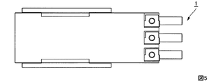
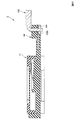
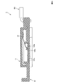
図1Aはスライダ11が初期位置に位置する場合の第一実施形態に係るスライドスイッチ1の正面図を、図1Bはスライダ11が動作後位置に位置する場合の正面図を示す。図2は第一実施形態に係るスライドスイッチ1の底面図を、図3はその左側面図を、図4はその右側面図を、図5はその背面図を示す。図6はスライドスイッチ1を正面側から見た斜視図を、図7はその分解斜視図を、図8はスライドスイッチ1を背面側から見た斜視図を、図9はその分解斜視図を示す。なお、各図において三つのハーネス151〜153を合わせて示し、図1A、図1B及び図6において可動部51を合わせて示している。
ボディ14は樹脂製であり、略矩形板状である。またボディ14には3つの端子131〜133がインサート成形されて形成されている(図10参照)。
スライダ11は樹脂製であり、略矩形板状である。スライダ11には、そのスライド移動方向と直交する幅方向両端の接片取付面上に突出して一対の係合片111が形成されている。係合片111の先端(遊端)には互いに内向きに係合爪111aが形成されている(図9及び図10参照)。
トングがバックル装置に挿入されると、バックル装置側に設けられている可動部51が押され、可動部51が初期位置から動作後位置方向に空走距離分を移動し、可動部51が係合穴115の一端部(右端)に係合し、可動部51によってスライダ11が押され動作後位置までスライド移動する。トングがバックル装置から抜去されると、バックル装置側の機構により、可動部51が初期位置までスライド移動して復帰し、それに伴いスライダ11が可動部51に押され初期位置までスライド移動して復帰する。言い換えると、バックル装置側の機構により、可動部51が動作後位置から初期位置方向に空走距離分を移動し、可動部51が係合穴115の他端部(左端)に係合し、可動部51によってスライダ11が押され初期位置までスライド移動する。スライダ11のスライド移動に伴い、可動接点121c及び122cが固定接点131aまたは132a上を摺動し、可動接点123c及び124cが固定接点133a上を摺動する。以下、詳細を説明する。
本実施形態では可動部51が動作してもスライダ11が動作しない空走距離を発生させる形状をスライダ11に持たせているのでシートベルトのバックル装置側の可動部51の動作範囲に関わらずスライドスイッチ1のスライダ11の動作範囲を小さく設定することができる。スライダ11の動作範囲を小さく設定することで、スライドスイッチ1のスライド移動方向の長さを小さくすることができ、小型化を実現できる。
スライドスイッチはバックル装置に組み込まれるものに限定されず、対象物の抜出状態と挿入係合状態とを検知する全般に利用することができる。特に、ON/OFFの出力信号のみを必要とし、可動部の動作範囲が大きく(ロングストローク)、かつその動作範囲を小さく設定することはできないが、スライドスイッチのスライド移動方向の長さを小さくしたい場合に有効である。
Claims (5)
- 対象物の抜出状態と挿入係合状態とを検知するスライドスイッチであって、
ボディと、
スライド可能に前記ボディに保持され、前記対象物の挿入によって押されてスライド移動するスライダと、
前記ボディの、前記スライダと対向する面にスライド移動方向に沿って配置されている固定接点を備える端子と、
前記スライダに取り付けられ、前記スライダのスライド移動に伴い、前記ボディの前記固定接点配置面上を摺動する可動接点を備える接片と、を含み、
前記スライダは、前記対象物の抜出及び挿入に伴いスライド移動方向に移動する可動部の動作を受ける係合部を備え、その係合部は前記可動部が動作しても前記スライダは動作しない空走距離を発生させる形状である、
スライドスイッチ。 - 請求項1記載のスライドスイッチであって、
前記可動部は柱形状部分を備えるものとし、前記スライダは、その前記可動部の動作を受ける面にスライド移動方向に延びる溝を有し、その溝のスライド移動方向の長さが前記柱形状部分のスライド移動方向の長さよりも長くなるように前記スライダが形成され、
前記柱形状部分と前記溝の端部とが係合して前記スライダはスライド移動する、
スライドスイッチ。 - 請求項1記載のスライドスイッチであって、
前記可動部はスライド移動方向に延びる溝状の係合穴を備えるものとし、前記スライダは、その前記可動部の動作を受ける面に突起を有し、その突起のスライド移動方向の長さが前記係合穴のスライド移動方向の長さよりも短くなるように前記スライダが形成され、
前記係合穴と前記突起の端部とが係合して前記スライダはスライド移動する、
スライドスイッチ。 - 請求項1から3の何れかに記載のスライドスイッチであって、
スライド移動の全範囲において、前記ボディ及び前記スライダが前記固定接点及び前記接片を全方位に対して覆う、
スライドスイッチ。 - 請求項1から3の何れかに記載のスライドスイッチであって、
前記ボディの前記固定接点配置面には、この固定接点配置面に対して垂直に立設され、その内部に前記固定接点が配される第一筒状部が形成され、前記スライダの前記接片取付面には、この接片取付面に対して垂直に立設され、その内部に前記接片及び前記第一筒状部が収容される第二筒状部が形成されている、
スライドスイッチ。
Priority Applications (7)
| Application Number | Priority Date | Filing Date | Title |
|---|---|---|---|
| JP2012002783A JP5769639B2 (ja) | 2012-01-11 | 2012-01-11 | スライドスイッチ |
| TW101144211A TWI527076B (zh) | 2012-01-11 | 2012-11-26 | Slide switch |
| KR1020120144081A KR20130082431A (ko) | 2012-01-11 | 2012-12-12 | 슬라이드 스위치 |
| CA2800597A CA2800597A1 (en) | 2012-01-11 | 2012-12-31 | Slide switch |
| EP13150144.7A EP2615618B1 (en) | 2012-01-11 | 2013-01-03 | Slide switch |
| US13/736,854 US8952283B2 (en) | 2012-01-11 | 2013-01-08 | Slide switch |
| CN201310006934.1A CN103208390B (zh) | 2012-01-11 | 2013-01-08 | 滑动开关 |
Applications Claiming Priority (1)
| Application Number | Priority Date | Filing Date | Title |
|---|---|---|---|
| JP2012002783A JP5769639B2 (ja) | 2012-01-11 | 2012-01-11 | スライドスイッチ |
Publications (2)
| Publication Number | Publication Date |
|---|---|
| JP2013143255A true JP2013143255A (ja) | 2013-07-22 |
| JP5769639B2 JP5769639B2 (ja) | 2015-08-26 |
Family
ID=47458814
Family Applications (1)
| Application Number | Title | Priority Date | Filing Date |
|---|---|---|---|
| JP2012002783A Expired - Fee Related JP5769639B2 (ja) | 2012-01-11 | 2012-01-11 | スライドスイッチ |
Country Status (7)
| Country | Link |
|---|---|
| US (1) | US8952283B2 (ja) |
| EP (1) | EP2615618B1 (ja) |
| JP (1) | JP5769639B2 (ja) |
| KR (1) | KR20130082431A (ja) |
| CN (1) | CN103208390B (ja) |
| CA (1) | CA2800597A1 (ja) |
| TW (1) | TWI527076B (ja) |
Families Citing this family (7)
| Publication number | Priority date | Publication date | Assignee | Title |
|---|---|---|---|---|
| JP5914250B2 (ja) | 2012-08-13 | 2016-05-11 | ホシデン株式会社 | On/off検出型バックルスイッチ |
| JP5871754B2 (ja) | 2012-09-04 | 2016-03-01 | ホシデン株式会社 | On/off検出型バックルスイッチ |
| CN106184115B (zh) * | 2013-11-12 | 2020-11-06 | 张国添 | 防欺骗式汽车安全带扣座的工作方法及汽车 |
| JP6278866B2 (ja) * | 2014-04-21 | 2018-02-14 | ホシデン株式会社 | プッシュスイッチ |
| USD831572S1 (en) * | 2017-11-20 | 2018-10-23 | The Charles Machine Works, Inc. | Electrical connection cover |
| CN108364810B (zh) * | 2018-03-26 | 2024-04-16 | 广东通宇通讯股份有限公司 | 一种通信天线用双模式切换开关及其组装方法 |
| JP7340490B2 (ja) | 2020-04-15 | 2023-09-07 | ホシデン株式会社 | シートベルト着脱検出スイッチ |
Citations (4)
| Publication number | Priority date | Publication date | Assignee | Title |
|---|---|---|---|---|
| JPS5681430U (ja) * | 1979-11-28 | 1981-07-01 | ||
| JPS57128727U (ja) * | 1981-02-05 | 1982-08-11 | ||
| JPS63187228U (ja) * | 1987-05-26 | 1988-11-30 | ||
| JPH0162628U (ja) * | 1987-10-14 | 1989-04-21 |
Family Cites Families (6)
| Publication number | Priority date | Publication date | Assignee | Title |
|---|---|---|---|---|
| DE10033403A1 (de) * | 2000-07-08 | 2002-01-17 | Hartmann Hans Georg Kg | Schalter, und Verfahren zu seiner Herstellung |
| US6333479B1 (en) * | 2001-01-04 | 2001-12-25 | Chi-Long Tai | Dual in-line type finger-actuated switch |
| US6483063B2 (en) * | 2001-03-14 | 2002-11-19 | Defond Manufacturing Limited | Electrical switch including a metal heat sink |
| JP4724071B2 (ja) * | 2006-08-10 | 2011-07-13 | 株式会社東海理化電機製作所 | スイッチ装置及び、その組立方法 |
| JP2009134950A (ja) * | 2007-11-29 | 2009-06-18 | Mitsumi Electric Co Ltd | プッシュスイッチ付きスライドスイッチ |
| JP5052579B2 (ja) * | 2009-09-18 | 2012-10-17 | ホシデン株式会社 | バックル装置用スライドスイッチ |
-
2012
- 2012-01-11 JP JP2012002783A patent/JP5769639B2/ja not_active Expired - Fee Related
- 2012-11-26 TW TW101144211A patent/TWI527076B/zh not_active IP Right Cessation
- 2012-12-12 KR KR1020120144081A patent/KR20130082431A/ko not_active Ceased
- 2012-12-31 CA CA2800597A patent/CA2800597A1/en not_active Abandoned
-
2013
- 2013-01-03 EP EP13150144.7A patent/EP2615618B1/en not_active Not-in-force
- 2013-01-08 US US13/736,854 patent/US8952283B2/en not_active Expired - Fee Related
- 2013-01-08 CN CN201310006934.1A patent/CN103208390B/zh not_active Expired - Fee Related
Patent Citations (4)
| Publication number | Priority date | Publication date | Assignee | Title |
|---|---|---|---|---|
| JPS5681430U (ja) * | 1979-11-28 | 1981-07-01 | ||
| JPS57128727U (ja) * | 1981-02-05 | 1982-08-11 | ||
| JPS63187228U (ja) * | 1987-05-26 | 1988-11-30 | ||
| JPH0162628U (ja) * | 1987-10-14 | 1989-04-21 |
Also Published As
| Publication number | Publication date |
|---|---|
| JP5769639B2 (ja) | 2015-08-26 |
| CA2800597A1 (en) | 2013-07-11 |
| EP2615618B1 (en) | 2014-08-13 |
| TWI527076B (zh) | 2016-03-21 |
| US8952283B2 (en) | 2015-02-10 |
| KR20130082431A (ko) | 2013-07-19 |
| CN103208390B (zh) | 2017-07-14 |
| US20130175152A1 (en) | 2013-07-11 |
| TW201334011A (zh) | 2013-08-16 |
| CN103208390A (zh) | 2013-07-17 |
| EP2615618A1 (en) | 2013-07-17 |
Similar Documents
| Publication | Publication Date | Title |
|---|---|---|
| JP5832308B2 (ja) | スライドスイッチ | |
| JP5769639B2 (ja) | スライドスイッチ | |
| JP5769638B2 (ja) | スライドスイッチ | |
| US9281610B2 (en) | Tray type card connector having a front cover with a sealing member | |
| CN101784173A (zh) | 电子设备 | |
| CN108615989A (zh) | 卡座组件、电子设备及其控制方法 | |
| JP3160739U (ja) | 電池ケースロック機構 | |
| US10014630B1 (en) | Card connector | |
| CN103296542B (zh) | 卡连接器 | |
| CN105590776B (zh) | 开关装置 | |
| JP2010135251A (ja) | 固定接点付きケース及びそれを備えたスライドスイッチ | |
| CN101770884B (zh) | 开关装置 | |
| SG188682A1 (en) | Electrical card connector | |
| JP4340645B2 (ja) | カード用コネクタ装置 | |
| CN101685931B (zh) | 电子装置及其卡片固定模块 | |
| JP2007227326A (ja) | カードコネクタ | |
| WO2018177501A1 (en) | Switch construction | |
| JP2010135252A (ja) | スライド型電気部品 | |
| JP2010068300A (ja) | 携帯機器 |
Legal Events
| Date | Code | Title | Description |
|---|---|---|---|
| A621 | Written request for application examination |
Free format text: JAPANESE INTERMEDIATE CODE: A621 Effective date: 20140819 |
|
| A977 | Report on retrieval |
Free format text: JAPANESE INTERMEDIATE CODE: A971007 Effective date: 20150410 |
|
| A131 | Notification of reasons for refusal |
Free format text: JAPANESE INTERMEDIATE CODE: A131 Effective date: 20150414 |
|
| A521 | Written amendment |
Free format text: JAPANESE INTERMEDIATE CODE: A523 Effective date: 20150520 |
|
| TRDD | Decision of grant or rejection written | ||
| A01 | Written decision to grant a patent or to grant a registration (utility model) |
Free format text: JAPANESE INTERMEDIATE CODE: A01 Effective date: 20150616 |
|
| A61 | First payment of annual fees (during grant procedure) |
Free format text: JAPANESE INTERMEDIATE CODE: A61 Effective date: 20150623 |
|
| R150 | Certificate of patent or registration of utility model |
Ref document number: 5769639 Country of ref document: JP Free format text: JAPANESE INTERMEDIATE CODE: R150 |
|
| LAPS | Cancellation because of no payment of annual fees |