JP2013144123A - Medical instrument - Google Patents
Medical instrument Download PDFInfo
- Publication number
- JP2013144123A JP2013144123A JP2013038650A JP2013038650A JP2013144123A JP 2013144123 A JP2013144123 A JP 2013144123A JP 2013038650 A JP2013038650 A JP 2013038650A JP 2013038650 A JP2013038650 A JP 2013038650A JP 2013144123 A JP2013144123 A JP 2013144123A
- Authority
- JP
- Japan
- Prior art keywords
- sensor
- skin
- analyte sensor
- guiding structure
- medical device
- Prior art date
- Legal status (The legal status is an assumption and is not a legal conclusion. Google has not performed a legal analysis and makes no representation as to the accuracy of the status listed.)
- Pending
Links
- 238000003780 insertion Methods 0.000 claims abstract description 119
- 230000037431 insertion Effects 0.000 claims abstract description 119
- 239000012491 analyte Substances 0.000 claims abstract description 34
- 230000007246 mechanism Effects 0.000 claims abstract description 21
- 238000002347 injection Methods 0.000 claims abstract description 14
- 239000007924 injection Substances 0.000 claims abstract description 14
- 239000007858 starting material Substances 0.000 claims description 6
- 230000004913 activation Effects 0.000 abstract description 2
- 239000000243 solution Substances 0.000 abstract 1
- 210000003491 skin Anatomy 0.000 description 70
- 239000000523 sample Substances 0.000 description 13
- 229920003023 plastic Polymers 0.000 description 12
- 238000010304 firing Methods 0.000 description 11
- 230000033001 locomotion Effects 0.000 description 11
- 239000004033 plastic Substances 0.000 description 11
- 238000005452 bending Methods 0.000 description 8
- 239000002184 metal Substances 0.000 description 8
- 229910052751 metal Inorganic materials 0.000 description 8
- 238000000034 method Methods 0.000 description 8
- WQZGKKKJIJFFOK-GASJEMHNSA-N Glucose Natural products OC[C@H]1OC(O)[C@H](O)[C@@H](O)[C@@H]1O WQZGKKKJIJFFOK-GASJEMHNSA-N 0.000 description 7
- 238000013459 approach Methods 0.000 description 7
- 238000001514 detection method Methods 0.000 description 7
- 239000008103 glucose Substances 0.000 description 7
- 241001465754 Metazoa Species 0.000 description 5
- 238000004891 communication Methods 0.000 description 5
- 241000124008 Mammalia Species 0.000 description 4
- 230000001965 increasing effect Effects 0.000 description 4
- NOESYZHRGYRDHS-UHFFFAOYSA-N insulin Chemical compound N1C(=O)C(NC(=O)C(CCC(N)=O)NC(=O)C(CCC(O)=O)NC(=O)C(C(C)C)NC(=O)C(NC(=O)CN)C(C)CC)CSSCC(C(NC(CO)C(=O)NC(CC(C)C)C(=O)NC(CC=2C=CC(O)=CC=2)C(=O)NC(CCC(N)=O)C(=O)NC(CC(C)C)C(=O)NC(CCC(O)=O)C(=O)NC(CC(N)=O)C(=O)NC(CC=2C=CC(O)=CC=2)C(=O)NC(CSSCC(NC(=O)C(C(C)C)NC(=O)C(CC(C)C)NC(=O)C(CC=2C=CC(O)=CC=2)NC(=O)C(CC(C)C)NC(=O)C(C)NC(=O)C(CCC(O)=O)NC(=O)C(C(C)C)NC(=O)C(CC(C)C)NC(=O)C(CC=2NC=NC=2)NC(=O)C(CO)NC(=O)CNC2=O)C(=O)NCC(=O)NC(CCC(O)=O)C(=O)NC(CCCNC(N)=N)C(=O)NCC(=O)NC(CC=3C=CC=CC=3)C(=O)NC(CC=3C=CC=CC=3)C(=O)NC(CC=3C=CC(O)=CC=3)C(=O)NC(C(C)O)C(=O)N3C(CCC3)C(=O)NC(CCCCN)C(=O)NC(C)C(O)=O)C(=O)NC(CC(N)=O)C(O)=O)=O)NC(=O)C(C(C)CC)NC(=O)C(CO)NC(=O)C(C(C)O)NC(=O)C1CSSCC2NC(=O)C(CC(C)C)NC(=O)C(NC(=O)C(CCC(N)=O)NC(=O)C(CC(N)=O)NC(=O)C(NC(=O)C(N)CC=1C=CC=CC=1)C(C)C)CC1=CN=CN1 NOESYZHRGYRDHS-UHFFFAOYSA-N 0.000 description 4
- 238000004519 manufacturing process Methods 0.000 description 4
- 239000000463 material Substances 0.000 description 4
- 230000008569 process Effects 0.000 description 4
- 230000001141 propulsive effect Effects 0.000 description 4
- 239000008280 blood Substances 0.000 description 3
- 210000004369 blood Anatomy 0.000 description 3
- 150000001875 compounds Chemical class 0.000 description 3
- 239000004020 conductor Substances 0.000 description 3
- 239000011162 core material Substances 0.000 description 3
- 238000013461 design Methods 0.000 description 3
- 230000001939 inductive effect Effects 0.000 description 3
- WABPQHHGFIMREM-UHFFFAOYSA-N lead(0) Chemical compound [Pb] WABPQHHGFIMREM-UHFFFAOYSA-N 0.000 description 3
- 238000000465 moulding Methods 0.000 description 3
- 238000010008 shearing Methods 0.000 description 3
- 102000004877 Insulin Human genes 0.000 description 2
- 108090001061 Insulin Proteins 0.000 description 2
- 210000004027 cell Anatomy 0.000 description 2
- 230000006835 compression Effects 0.000 description 2
- 238000007906 compression Methods 0.000 description 2
- 230000008878 coupling Effects 0.000 description 2
- 238000010168 coupling process Methods 0.000 description 2
- 238000005859 coupling reaction Methods 0.000 description 2
- 238000002788 crimping Methods 0.000 description 2
- 238000010586 diagram Methods 0.000 description 2
- 239000003814 drug Substances 0.000 description 2
- 229940079593 drug Drugs 0.000 description 2
- 239000012530 fluid Substances 0.000 description 2
- 239000006260 foam Substances 0.000 description 2
- 230000006870 function Effects 0.000 description 2
- 208000014674 injury Diseases 0.000 description 2
- 229940125396 insulin Drugs 0.000 description 2
- 150000002739 metals Chemical class 0.000 description 2
- 238000012544 monitoring process Methods 0.000 description 2
- 230000035515 penetration Effects 0.000 description 2
- 230000002441 reversible effect Effects 0.000 description 2
- 238000007789 sealing Methods 0.000 description 2
- 210000000434 stratum corneum Anatomy 0.000 description 2
- 230000008733 trauma Effects 0.000 description 2
- 230000001960 triggered effect Effects 0.000 description 2
- 102000004190 Enzymes Human genes 0.000 description 1
- 108090000790 Enzymes Proteins 0.000 description 1
- BQCADISMDOOEFD-UHFFFAOYSA-N Silver Chemical compound [Ag] BQCADISMDOOEFD-UHFFFAOYSA-N 0.000 description 1
- 229910000831 Steel Inorganic materials 0.000 description 1
- 230000009471 action Effects 0.000 description 1
- 230000006978 adaptation Effects 0.000 description 1
- 238000004026 adhesive bonding Methods 0.000 description 1
- 230000005540 biological transmission Effects 0.000 description 1
- 210000001124 body fluid Anatomy 0.000 description 1
- 239000010839 body fluid Substances 0.000 description 1
- 238000006243 chemical reaction Methods 0.000 description 1
- 238000005253 cladding Methods 0.000 description 1
- 230000001419 dependent effect Effects 0.000 description 1
- 230000000881 depressing effect Effects 0.000 description 1
- 206010012601 diabetes mellitus Diseases 0.000 description 1
- 201000010099 disease Diseases 0.000 description 1
- 208000037265 diseases, disorders, signs and symptoms Diseases 0.000 description 1
- 230000000694 effects Effects 0.000 description 1
- 210000003722 extracellular fluid Anatomy 0.000 description 1
- 230000003116 impacting effect Effects 0.000 description 1
- 230000006698 induction Effects 0.000 description 1
- 208000015181 infectious disease Diseases 0.000 description 1
- 230000009545 invasion Effects 0.000 description 1
- 230000007774 longterm Effects 0.000 description 1
- 238000005259 measurement Methods 0.000 description 1
- 230000003287 optical effect Effects 0.000 description 1
- 235000015927 pasta Nutrition 0.000 description 1
- 230000037368 penetrate the skin Effects 0.000 description 1
- 230000000149 penetrating effect Effects 0.000 description 1
- 230000037081 physical activity Effects 0.000 description 1
- 230000035790 physiological processes and functions Effects 0.000 description 1
- 239000002985 plastic film Substances 0.000 description 1
- 238000005381 potential energy Methods 0.000 description 1
- 238000004382 potting Methods 0.000 description 1
- 238000002360 preparation method Methods 0.000 description 1
- 238000003825 pressing Methods 0.000 description 1
- 238000012545 processing Methods 0.000 description 1
- 230000001681 protective effect Effects 0.000 description 1
- 231100000241 scar Toxicity 0.000 description 1
- 230000001568 sexual effect Effects 0.000 description 1
- 229910001285 shape-memory alloy Inorganic materials 0.000 description 1
- 230000008054 signal transmission Effects 0.000 description 1
- 230000011664 signaling Effects 0.000 description 1
- 229910052709 silver Inorganic materials 0.000 description 1
- 239000004332 silver Substances 0.000 description 1
- 238000005476 soldering Methods 0.000 description 1
- 239000010959 steel Substances 0.000 description 1
- 210000001519 tissue Anatomy 0.000 description 1
- 238000012546 transfer Methods 0.000 description 1
Images









Classifications
-
- A—HUMAN NECESSITIES
- A61—MEDICAL OR VETERINARY SCIENCE; HYGIENE
- A61B—DIAGNOSIS; SURGERY; IDENTIFICATION
- A61B17/00—Surgical instruments, devices or methods
- A61B17/34—Trocars; Puncturing needles
- A61B17/3403—Needle locating or guiding means
-
- A—HUMAN NECESSITIES
- A61—MEDICAL OR VETERINARY SCIENCE; HYGIENE
- A61B—DIAGNOSIS; SURGERY; IDENTIFICATION
- A61B5/00—Measuring for diagnostic purposes; Identification of persons
- A61B5/68—Arrangements of detecting, measuring or recording means, e.g. sensors, in relation to patient
- A61B5/6846—Arrangements of detecting, measuring or recording means, e.g. sensors, in relation to patient specially adapted to be brought in contact with an internal body part, i.e. invasive
- A61B5/6847—Arrangements of detecting, measuring or recording means, e.g. sensors, in relation to patient specially adapted to be brought in contact with an internal body part, i.e. invasive mounted on an invasive device
- A61B5/6848—Needles
- A61B5/6849—Needles in combination with a needle set
-
- A—HUMAN NECESSITIES
- A61—MEDICAL OR VETERINARY SCIENCE; HYGIENE
- A61B—DIAGNOSIS; SURGERY; IDENTIFICATION
- A61B17/00—Surgical instruments, devices or methods
- A61B17/34—Trocars; Puncturing needles
- A61B17/3468—Trocars; Puncturing needles for implanting or removing devices, e.g. prostheses, implants, seeds, wires
-
- A—HUMAN NECESSITIES
- A61—MEDICAL OR VETERINARY SCIENCE; HYGIENE
- A61B—DIAGNOSIS; SURGERY; IDENTIFICATION
- A61B5/00—Measuring for diagnostic purposes; Identification of persons
- A61B5/145—Measuring characteristics of blood in vivo, e.g. gas concentration or pH-value ; Measuring characteristics of body fluids or tissues, e.g. interstitial fluid or cerebral tissue
- A61B5/14532—Measuring characteristics of blood in vivo, e.g. gas concentration or pH-value ; Measuring characteristics of body fluids or tissues, e.g. interstitial fluid or cerebral tissue for measuring glucose, e.g. by tissue impedance measurement
Landscapes
- Health & Medical Sciences (AREA)
- Life Sciences & Earth Sciences (AREA)
- Surgery (AREA)
- Medical Informatics (AREA)
- Public Health (AREA)
- Engineering & Computer Science (AREA)
- Biomedical Technology (AREA)
- Heart & Thoracic Surgery (AREA)
- Veterinary Medicine (AREA)
- Molecular Biology (AREA)
- Pathology (AREA)
- Animal Behavior & Ethology (AREA)
- General Health & Medical Sciences (AREA)
- Biophysics (AREA)
- Physics & Mathematics (AREA)
- Nuclear Medicine, Radiotherapy & Molecular Imaging (AREA)
- Measurement Of The Respiration, Hearing Ability, Form, And Blood Characteristics Of Living Organisms (AREA)
- Infusion, Injection, And Reservoir Apparatuses (AREA)
Abstract
Description
本発明は全般的に、多種の医療用機能又は生理学的機能を実施するよう、皮膚を通って体内へと機械的に細長い装置を運ぶ装置に係る。より具体的には、本発明は、剛性及び/又は鋭利な導入装置の支援を有することなく、あるいは汚染された鋭利な導入装置を廃棄する必要なく、安全且つ自動的に軟質のカニューレバイオセンサ又は可撓性のバイオセンサを経皮的配置に対する方法に係る。 The present invention generally relates to a device that mechanically carries an elongated device through the skin and into the body to perform a variety of medical or physiological functions. More specifically, the present invention provides a safe and automatically flexible cannula biosensor or without the need for rigid and / or sharp introducer assistance or the need to discard contaminated sharp introducers. A method for percutaneous placement of a flexible biosensor.
医療上に使用される装置の例は複数有り、該装置は、機械的に細長く且つ可撓性があり、また、皮膚を通って挿入される。 There are several examples of medically used devices that are mechanically elongated and flexible, and are inserted through the skin.
例えば、センサは、患者の体内の特定の状態の検出を容易にする。電気化学的センサは一般的に、糖尿病の管理において血糖値を監視するよう使用される。あるスキームでは、酵素を組み込む電気化学的センサは、小さな直径のワイヤ上に作られる。第2の基準電極はまた、検出電極の近くにおいてワイヤの周囲に作られる。センサ組立体は、間質液によって取り囲まれるよう、皮膚を介して挿入される。センサ組立体の一部は、皮膚を出て、身体の外部に残り、そこで検出電極及び基準電極に対する電気接続がなされ得る。身体の外側における適切な電子計測装置は、血糖値を記録及び表示するようセンサからの電流を測定するよう使用され得る。かかる種類の装置は、例えば、Heller外による米国特許第5,965,380号明細書(特許文献1)、及びWard外による米国特許第5,165,407号明細書(特許文献2)において説明される。 For example, sensors facilitate the detection of specific conditions within the patient's body. Electrochemical sensors are commonly used to monitor blood glucose levels in diabetes management. In one scheme, an electrochemical sensor incorporating an enzyme is made on a small diameter wire. A second reference electrode is also made around the wire near the detection electrode. The sensor assembly is inserted through the skin so as to be surrounded by the interstitial fluid. A portion of the sensor assembly exits the skin and remains outside the body where an electrical connection can be made to the detection and reference electrodes. A suitable electronic measuring device outside the body can be used to measure the current from the sensor to record and display the blood glucose level. Such a device is described, for example, in US Pat. No. 5,965,380 by Heller et al. And US Pat. No. 5,165,407 by Ward et al. Is done.
電気化学的グルコースセンサに加えて、複数の他の電気化学的センサは、血液又は他の体液の化学的性質又は材質を測定するよう開発されている。電気化学的センサは、一般的には、パラメータを測定するよう1つ又はそれより多い電気化学的工程及び電気信号を利用する。他の種類のセンサは、測定を実施するよう光学技術を使用する工程及び信号を有する。 In addition to electrochemical glucose sensors, a number of other electrochemical sensors have been developed to measure the chemistry or material of blood or other body fluids. Electrochemical sensors typically utilize one or more electrochemical processes and electrical signals to measure parameters. Other types of sensors have steps and signals that use optical techniques to perform measurements.
他の適用において、カニューレとセンサとを組み合わせた装置は、皮膚を介して挿入され、インシュリンが人工膵臓系の一部として体内へと導入されるようにする。かかる適用において、細長く(断面が小さい)可撓性の装置は、より大きくより剛性な装置に対して複数の利点を有する。患者の安心感は、特には長期間の挿入中において増大し、侵入部位における外傷は、低減される。可撓性の装置はまた、身体活動中の皮膚の動きに対して調整することができ、患者の安心感を増大させる。多くの場合において、かかる装置は、5乃至7日間体内に挿入されたままである。 In other applications, a combined cannula and sensor device is inserted through the skin to allow insulin to be introduced into the body as part of an artificial pancreatic system. In such applications, elongated (small cross-section) flexible devices have several advantages over larger and more rigid devices. Patient comfort increases, especially during long-term insertion, and trauma at the entry site is reduced. The flexible device can also be adjusted for skin movement during physical activity, increasing patient comfort. In many cases, such devices remain inserted into the body for 5-7 days.
かかる装置の細長く可撓性のある特性は患者の安心感を増大させはするが、このような装置は、皮膚を介する挿入が困難である。典型的な皮下注射の針とは異なり、該装置は、脆弱且つ柔らかすぎるため、通常の力及び速度を使用して皮膚表面を介して単純に押され得ない。かかる装置の先端が皮膚に対して押し進められる際、装置は、皮膚侵入を達成するよう求められるより大幅に小さい力で曲がってつぶれる。場合によっては容易に侵入するよう装置の先端が鋭くされ得るが、このアプローチは、典型的には侵入を確実なものとするには適切ではなく、管状の装置等である複数の装置は、鋭利にされるよう適切ではない。また、鋭利にする工程は、製造コスト及び複雑性を増大させる。 Although the slender and flexible nature of such devices increases patient comfort, such devices are difficult to insert through the skin. Unlike typical hypodermic needles, the device is too fragile and too soft to be simply pushed through the skin surface using normal forces and speeds. As the tip of such a device is pushed against the skin, the device bends and collapses with much less force than is required to achieve skin penetration. Although in some cases the tip of the device can be sharpened to easily penetrate, this approach is typically not appropriate to ensure penetration, and multiple devices, such as tubular devices, are sharp. Not appropriate to be. The sharpening process also increases manufacturing costs and complexity.
当業者には理解される通り、ヒト(人間)の皮膚は、比較的不可入性の外側層、角質層、及びより容易に侵入される内側層に影響される生体力学的特性を有する。かかる生体力学的特性によって、皮膚表面の侵入は、比較的脆弱で細長く可撓性のある装置を皮膚へと導入することにおいて主な問題を示すようにされる。 As will be appreciated by those skilled in the art, human skin has biomechanical properties that are affected by the relatively impervious outer layer, the stratum corneum, and the more easily invaded inner layer. Such biomechanical properties make skin surface invasion present a major problem in introducing relatively fragile, slender and flexible devices into the skin.
先行技術は、かかる細長く可撓性の装置の皮膚を介する挿入に対して複数の手法を与える。ある場合においては、装置は、皮下注射の針又はトロカール等である鋭利な端部を有する中空の管の内部において同軸に配置される。針は、内部の装置と共に皮膚を通って挿入される。第2の段階として、針は、引き込められ、装置をあとに残し、皮膚を通って体内へ入る。例えば、Ward外による米国特許第6,695,860号明細書(特許文献3)が参照される。挿入工程は、大きな直径の針により、痛みを伴い得、装置のみが通るよう必要とされるよりも大きな開口が皮膚に作られ、外傷及び感染の可能性を高める。 The prior art provides multiple approaches to the insertion of such elongated flexible devices through the skin. In some cases, the device is placed coaxially inside a hollow tube with a sharp end, such as a hypodermic needle or trocar. The needle is inserted through the skin with the internal device. As a second step, the needle is retracted, leaving the device behind and through the skin into the body. See, for example, US Pat. No. 6,695,860 by Ward et al. The insertion process can be painful due to the large diameter needle, creating a larger opening in the skin than is required for only the device to pass, increasing the possibility of trauma and infection.
この手法の変形では、装置の機能は、皮膚へと挿入されたままにされなければならない薄い針へと組み込まれる。針は、皮膚を貫通する支援をするよう鋭利な先端及び更なる機械的強度を与える。しかしながら、より大きな寸法及び剛性により、この手法も、挿入の間患者に不快感を与える一因である。例えば、米国特許第6,501,976号明細書(特許文献4)が参照される。 In a variation of this approach, the functionality of the device is incorporated into a thin needle that must be left inserted into the skin. The needle provides a sharp tip and additional mechanical strength to assist in penetrating the skin. However, due to the larger dimensions and stiffness, this approach also contributes to patient discomfort during insertion. For example, see US Pat. No. 6,501,976 (Patent Document 4).
更には、剛性な針の存在は、装置が皮膚を出るところである皮膚の表面に対して取り付けられる装置筐体の寸法及び形状に対して、機械的制約を与える。また、装置挿入において使用されたあとに他の個人の皮膚を誤って刺した場合、病気を移すことがあり得るため、針は、生物学的有害物質「鋭利なもの」(a biohazard “sharp”)として扱われなければならない。 Furthermore, the presence of a rigid needle places mechanical constraints on the size and shape of the device housing that is attached to the surface of the skin where the device exits the skin. In addition, the needle can be used to insert a biohazard “sharp” because it can transfer disease if accidentally stabbed into another person's skin after being used in the device insertion. ) Must be treated as.
上記課題に対して、針等である導入装置を使用することなく哺乳類の皮膚に入り得る医療機器を提供することを目的とする。 In order to solve the above problems, an object of the present invention is to provide a medical device that can enter the skin of a mammal without using an introduction device such as a needle.
可撓性の検体センサと、前記可撓性の検体センサを皮膚へと挿入する挿入装置とを含む医療機器であって、
前記挿入装置は、
前記可撓性の検体センサに対して軸方向支持を与えるよう適合され、また、使用時に前記皮膚に対して外部にあるよう適合される誘導構造であって、当該誘導構造は出口部を有する、誘導構造と、
前記誘導構造に関連付けられる注射始動装置であって、当該注射始動装置は、前記可撓性の検体センサに対して高速推進力を適用するよう適合される機構を有し、制御された衝撃及び駆動力が、前記可撓性の検体センサに適用され、前記可撓性の検体センサは、前記誘導構造を少なくとも部分的に通って、かつ、前記誘導構造とは独立して動き、かつ、前記出口部を少なくとも部分的に通過して、前記皮膚への前記可撓性の検体センサの挿入が引き起こされる、注射始動装置と、
を有し、
前記挿入装置は、前記皮膚への前記可撓性の検体センサの挿入を、剛性を有する及び/又は鋭利な導入装置無しで引き起こすよう構成される、
医療機器。
A medical device comprising a flexible analyte sensor and an insertion device for inserting the flexible analyte sensor into the skin,
The insertion device is
A guiding structure adapted to provide axial support to the flexible analyte sensor and adapted to be external to the skin in use, the guiding structure having an outlet portion; A guiding structure;
An injection starter associated with the guide structure, the injection starter having a mechanism adapted to apply a high speed propulsion force to the flexible analyte sensor for controlled impact and drive Force is applied to the flexible analyte sensor, the flexible analyte sensor moving at least partially through the guidance structure and independent of the guidance structure, and the outlet An injection triggering device that is at least partially passed through a section to cause insertion of the flexible analyte sensor into the skin;
Have
The insertion device is configured to cause insertion of the flexible analyte sensor into the skin without a rigid and / or sharp introducer;
Medical equipment.
針等である導入装置を使用することなく哺乳類の皮膚に入り得る医療機器を提供できる。 A medical device that can enter the skin of a mammal without using an introduction device such as a needle can be provided.
本発明の実施例は、添付の図面と併せて以下の詳細な説明によって容易に理解される。本明細書において、同様の参照符号は、同様の構造上要素を示す。本発明の実施例は、添付の図中、制限的ではなく例証として図示される。 Embodiments of the present invention will be readily understood by the following detailed description in conjunction with the accompanying drawings. In the specification, like reference numerals indicate like structural elements. Embodiments of the invention are illustrated by way of example and not limitation in the accompanying figures.
以下の詳細な説明において、添付の図面が参照される。図中、同様の参照符号は同様の部分を示し、本発明が実行され得る実施例を図示する目的で示される。他の実施例が利用され得ること、及び構造上又は論理上の変更が本発明の範囲から逸脱せずになされ得ることは、理解されるべきである。したがって、以下の詳細な説明は、制限的なものではなく、本発明にしたがった実施例の範囲は、添付の請求項及びそれと同等のものによって定義される。 In the following detailed description, reference is made to the accompanying drawings. In the drawings, like reference numerals indicate like parts and are shown for the purpose of illustrating embodiments in which the invention may be practiced. It is to be understood that other embodiments can be utilized and that structural or logical changes can be made without departing from the scope of the present invention. The following detailed description is, therefore, not to be taken in a limiting sense, and the scope of the embodiments according to the present invention is defined by the appended claims and their equivalents.
多種の動作は、本発明の実施例を理解する支援をし得るよう、同様に複数の別個の動作として説明され得る。しかしながら、記載の順序は、かかる動作が順序依存性であることを意味するものとして解釈されるべきではない。 The various operations may be described as a plurality of separate operations as well, to assist in understanding embodiments of the present invention. However, the order of description should not be construed to imply that such operations are order dependent.
本明細書(請求項を含む)は、上方/下方、後方/前方、及び上部/下部等である透視的記載を使用し得る。かかる記載は、単に説明を容易にするよう使用されるものであり、本発明の実施例の適用を制限することは意図されない。 This specification (including claims) may use perspective descriptions such as up / down, back / front, top / bottom, and the like. Such descriptions are merely used to facilitate the description and are not intended to limit the application of embodiments of the present invention.
本発明の目的に対して、「A/B」という形式における語句は、A又はBを意味する。本発明の目的に対して、「A及び/又はB」という形式における語句は、「(A)、(B)、又は(A及びB)」を意味する。本発明の目的に対して、「A、B、及びCのうち少なくとも1つ」という形式における語句は、「(A)、(B)、(C)、(A及びB)、(A及びC)、(B及びC)、(A、B、及びC)」を意味する。本発明の目的に対して、「(A)B」は「(B)又は(AB)」、即ちAが任意の要素であることを意味する。 For the purposes of the present invention, a phrase in the form “A / B” means A or B. For purposes of the present invention, a phrase in the form “A and / or B” means “(A), (B), or (A and B)”. For the purposes of the present invention, a phrase in the form “at least one of A, B, and C” refers to “(A), (B), (C), (A and B), (A and C ), (B and C), (A, B, and C) ". For the purposes of the present invention, “(A) B” means “(B) or (AB)”, ie, A is an optional element.
本明細書は、「一実施例では」又は「実施例では」という語句を使用し得、該語句は、1つ又はそれ以上の同一又は異なる実施例を各々示し得る。更には、本発明の実施例に対して使用される「有する」、「含む」及びそれと同等の語は、同義である。 This specification may use the phrases “in one embodiment” or “in an embodiment”, which may each denote one or more of the same or different embodiments. Furthermore, the terms “comprising”, “including” and equivalent terms used for the embodiments of the present invention are synonymous.
本発明の実施例及び請求項を説明することを目的として、「高速推進力(“high speed motive force”)」という語は、センサを実質的に屈曲させること又は実質的に偏向させることなく、例えば約0.5N/mm又は10N/mmの力等である、(比較的不可入性の外側層、角質層、及びより容易に侵入される内側層を有する)動物の皮膚へと薄く可撓性のある医療用装置を駆動させるよう十分な力、を指すものである。当業者には明らかである通り、薄く可撓性のある医療装置を動物の皮膚へと駆動するよう必要とされる力は、該医療装置が動物の皮膚の表面が与える抵抗以外の他の抵抗にあう場合に増大する。該抵抗とは、例えば瘢痕組織、又は医療装置が通らなければならない管又は誘導構造がもたらす摩擦抵抗である。「高速推進力」という表現は、医療装置がかかる他の抵抗にあい得る場合において薄く可撓性のある医療装置を動物の皮膚へと駆動するよう必要とされる力、を包含する。言い換えれば、「高速推進力」という表現は、推進力が適用される際に医療装置上に作用する全ての力の合計が動物の皮膚へと医療装置を駆動させるよう十分であるよう、薄く可撓性のある医療装置に対して適用される必要がある推進力の量、を包含する。 For purposes of describing embodiments and claims of the present invention, the term “high speed motive force” is used without substantially bending or substantially deflecting the sensor, Thin and flexible to the animal's skin (with a relatively impervious outer layer, stratum corneum, and more easily invaded inner layer), such as a force of about 0.5 N / mm or 10 N / mm It refers to a force sufficient to drive a sexual medical device. As will be apparent to those skilled in the art, the force required to drive a thin and flexible medical device into the animal's skin is a resistance other than that provided by the surface of the animal's skin. It increases when meeting. The resistance is the frictional resistance provided by, for example, scar tissue or a tube or guiding structure through which a medical device must pass. The expression “fast propulsion” includes the force required to drive a thin and flexible medical device into the animal's skin where the medical device can meet such other resistances. In other words, the expression “fast propulsion” can be thin enough that the sum of all forces acting on the medical device when the propulsion is applied is sufficient to drive the medical device to the animal's skin. Including the amount of propulsion that needs to be applied to the flexible medical device.
「アクチュエータ」という語は、何かを動かす又は制御する、多種の電気、水圧、磁気、空気圧、又は他の手段のいずれかを示す。「ソレノイドアクチュエータ」という語は、電気エネルギを直線又は回転動作へと変換する多種の電気機械装置を示す。「トリガ」という語は、工程又は反応を開始する、多種の電気、水圧、磁気、空気圧、又は他の手段のいずれかを示す。「サボット(“sabot”)」という語は、中心ホールを有する厚い円形のディスクを示す。 The term “actuator” refers to any of a variety of electrical, hydraulic, magnetic, pneumatic, or other means of moving or controlling something. The term “solenoid actuator” refers to a variety of electromechanical devices that convert electrical energy into linear or rotational motion. The term “trigger” refers to any of a variety of electrical, hydraulic, magnetic, pneumatic, or other means that initiate a process or reaction. The term “sabot” refers to a thick circular disc with a central hole.
本発明の実施例及び請求項における記載を目的として、「軸方向支持」という語は、装置の長さ方向を通って引かれる仮想線に対して垂直に作用する力のベクトルに抵抗するよう、比較的真っ直ぐな細長い物体に対して推進力が適用される際に、該物体を支持又はブレーシングすることを意味する。かかる支持又はブレーシングは、真っ直ぐで細長い物体のクリンピング、しわ、折畳み、又は屈曲を防ぐあるいは低減するよう十分である。あるいは、かかる支持又はブレーシングは、物体が最小限の屈曲後に比較的真っ直ぐな構造まで戻り得るよう十分であり、物体は、最小限のクリンピング、しわ、折畳み、又は屈曲を有してその形状を実質的に保持する。 For the purpose of describing embodiments and claims of the present invention, the term “axial support” is intended to resist a force vector acting perpendicular to an imaginary line drawn through the length of the device. When propulsive force is applied to a relatively straight elongate object, it means to support or brace the object. Such support or bracing is sufficient to prevent or reduce crimping, wrinkling, folding, or bending of straight and elongated objects. Alternatively, such support or bracing is sufficient to allow the object to return to a relatively straight structure after minimal bending, and the object has its shape with minimal crimping, wrinkling, folding, or bending. Hold substantially.
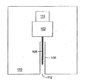
本発明の実施例及び請求項における記載を目的として、「関連付けられる」という語は、物体、要素、又は機能が、他の物体、要素、又は機能に対してあるいはそれらに近接して結合又は接続され、また、それらに連通する、ことを指す。例えば、図1中に記載される通り、機構102は、検体センサ108に対して高速推進力を適用し得、検体センサ108が誘導構造106を通って動くようにする。したがって機構102は、誘導構造106の近くにあり且つ誘導構造106と連通し、故に誘導構造106と「関連付けられる」。
For the purpose of describing embodiments and claims of the present invention, the term “associated with” means that an object, element, or function is coupled or connected to or in proximity to another object, element, or function. And also communicate with them. For example, as described in FIG. 1, the
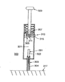
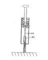
他の例では、図3Aに示される通り、スプリング307は、センサ301に向かってプランジャ305を押し下げ得、誘導構造303を通ってセンサ301を駆動し得る。したがって、プランジャ305及びスプリング307は、誘導構造303と練通し、故に誘導構造303と「関連付けられる」。プランジャ305及びスプリング307は、誘導構造303と物理的に接触してもしなくてもよく、静止位置にある際に接触してもしなくてもよい。また、図3中、スプリング307は、プランジャ305と関連付けられる。即ち、スプリング307は、プランジャ305に対して接続される。
In another example, as shown in FIG. 3A, the
他の例では、図6Aにおいて示される通り、スライダ605は、誘導構造601に対して結合され、挿入スプリング603は、スライダ605を誘導構造601の上部にわたって動かし得る。このようにして、挿入スプリング603及びスライダ605はいずれも、湾曲した誘導構造601に「関連付けられる」。
In another example, as shown in FIG. 6A,
図10に示される更に他の例では、CO2カートリッジ1001は、CO2ガスをマニホールド1003へと放出し得る。該マニホールドは、ガスが内部バルブ(図示せず)を通過し、中空ピン1009に入るようにし得、該中空ピンは、ロッド1011を前進させて挿入に対してセンサ(図示せず)にぶつかる(striking)。したがって、CO2カートリッジ1001は、センサ(図示せず)と連通し、故にセンサと「関連付けられる」。
In yet another example shown in FIG. 10, the
本発明の実施例及び請求項における記載を目的として、「ガイド部材」という語は、検体センサを少なくとも部分的に軸方向に取り囲み、且つ誘導構造内部に合うよう適合される装置、を意味し、ガイド部材は、挿入中、挿入前、及び/又は挿入後のいずれかにおいて、センサと誘導構造との間における空間の少なくとも一部を少なくとも部分的に占有する。ガイド部材は、軸方向支持を与え得るか、あるいは誘導構造を通って動くセンサを支援するかのいずれか、あるいはそれらの両方であり得る。典型的なガイド部材は、サボット、プラスチックの螺旋、矩形の金属ガイド、開放セルフォームプラスチック(open cell foam plastic)シリンダ、及び薄いプラスチックディスクを有する。当業者には理解される通り、ガイド部材は、多くの異なる材料を有して作られ得、誘導構造の形状に対応し得るあるいは対応し得ない多種の形状において、形成され得る。 For the purpose of describing embodiments and claims of the present invention, the term “guide member” means a device that at least partially surrounds the analyte sensor in the axial direction and is adapted to fit within the guiding structure; The guide member at least partially occupies at least a portion of the space between the sensor and the guiding structure either during insertion, before insertion, and / or after insertion. The guide member may either provide axial support or assist the sensor moving through the guiding structure, or both. Typical guide members include sabots, plastic spirals, rectangular metal guides, open cell foam plastic cylinders, and thin plastic discs. As will be appreciated by those skilled in the art, the guide member can be made of many different materials and can be formed in a variety of shapes that may or may not correspond to the shape of the guiding structure.
本発明の実施例及び請求項における記載を目的として、「電気ネットワーク」という語は、部分的には、関連付けられたセンサからの電気信号を受信するよう、また、任意では、センサ信号に応答する外部電子監視ユニット等に対して更なる信号を送信するよう、適合される所望の構造的関係における、電子回路及び構成要素を意味する。回路及び他の構成要素は、プリント回路基板、つなぎ(tethered)システム又は有線システム等を有しても有さなくてもよい。信号送信は、RF通信等である電磁波を有して無線で発生し得るか、あるいは、データは、誘導結合を使用して読まれ得る。他の実施例では、送信は、有線であるいは他の直接接続を介してなされ得る。 For purposes of description of embodiments and claims of the present invention, the term “electrical network” will, in part, receive an electrical signal from an associated sensor and optionally respond to the sensor signal. It means electronic circuits and components in a desired structural relationship adapted to send further signals to an external electronic monitoring unit or the like. The circuitry and other components may or may not have a printed circuit board, a tethered system, a wired system, or the like. The signal transmission can occur wirelessly with electromagnetic waves, such as RF communications, or the data can be read using inductive coupling. In other embodiments, the transmission can be made in a wired or other direct connection.
本発明の一実施例は、図1中に示される通り、検体センサ108の挿入に対して適合され得る誘導構造106に対して結合される高速推進力を生成するよう結合される機構102を有し得る。機構102は、トリガ114によって制御され得る。本発明の多種の実施例では、検体センサ108は、誘導構造を通って誘導構造開口112を出る機構102によって生成される高速推進力によって駆動され得る。図1では、誘導構造開口112は、筐体110のエッジ部と同一平面であるよう図示される。しかしながら、実施例では、誘導構造開口は、筐体110の外側に配置され得るか、あるいは筐体110のより大きな開口の内側に入れ子にされ得る。
One embodiment of the present invention has a
実施例では、誘導構造は、円形の断面を有する中空の管であり得る。実施例では、誘導構造は、直線状であり得る。実施例では、誘導構造は、センサが挿入されるべき皮膚に対して垂直である方向以外の方向においてセンサに対して推進力が適用されるよう湾曲され得る。実施例では、誘導構造は、円形の断面を有する湾曲された中空の管であり得る。 In an embodiment, the guiding structure can be a hollow tube having a circular cross section. In an embodiment, the guiding structure can be linear. In an embodiment, the guiding structure may be curved so that a driving force is applied to the sensor in a direction other than the direction that is perpendicular to the skin into which the sensor is to be inserted. In an embodiment, the guiding structure may be a curved hollow tube having a circular cross section.
多種の実施例では、開口112が位置付けられる筐体110のエッジは、挿入に先立って皮膚に対して同一平面に配置され得る。皮膚と同一平面上に筐体11のエッジを配置することは、センサのバックリング又は偏向なくセンサを挿入するよう支援し得る皮膚表面上の張力を生成し得る。誘導構造112が筐体110の表面を越えて延在する一実施例においては、皮膚に対して張力を与え得るのは、皮膚に対する誘導構造112の圧力であり得る。
In various embodiments, the edge of the
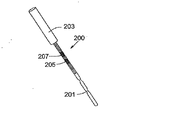
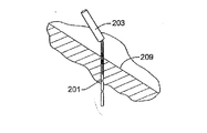
図2Aは、本発明の多種の実施例に従って挿入され得る検体センサ200を示す。図2A中、検体センサ200は、ある長さの薄く可撓性のあるワイヤ上へと作られている電気化学的グルコースセンサである。基準又はグラウンド電極205及び検出電極207は、検体センサ200へと組み込まれ得る。センサ200の小さな直径の端部201(近位端部)は、皮膚を通って挿入され得る。一実施例では、この直径は、約0.25mm又はそれより小さくあり得る。一実施例では、センサ200のより大きな直径端部(遠位端部)上で、その直径は、剛性を増大させ得且つ電気的接続を促進し得る鋼管203のスリーブを加えることによって、増大されている。複数の実施例では、より大きな断面の直径は、例えば約0.5mmであり得る。一実施例では、センサのより大きな直径部分は、挿入時に身体の外側に残り得る。図2Bは、皮膚へと挿入される際のセンサの断面を示す。複数の実施例では、例えば約15mmである10−20mmの長さのセンサ200は、皮膚の下方に差し込まれ得る。
FIG. 2A illustrates an
実施例において、本発明の一実施例に従って挿入されるセンサは、剛性又は可撓性であり得る。複数の実施例において、可撓性のセンサは、破損することなくある期間(例えば3−7日間又はそれより長く)にわたって、反復的に屈曲され得るものであり、例えば該屈曲は、通常の運動中に人間において皮下埋込みされるセンサによって与えられる屈曲の種類である。一実施例では、可撓性のセンサは、破損することなく、数百回又は数千回屈曲され得る。 In an embodiment, a sensor inserted in accordance with an embodiment of the present invention can be rigid or flexible. In embodiments, the flexible sensor can be flexed repeatedly over a period of time (eg, 3-7 days or longer) without breaking, eg, the flexing is a normal motion A type of flexion imparted by a sensor that is implanted subcutaneously in humans. In one example, a flexible sensor can be bent hundreds or thousands of times without breaking.
図3Aは、本発明の一実施例に従った挿入装置を示す。センサ301は、挿入装置300内部において誘導構造303へと配置され得る。一実施例では、誘導構造303は、センサ301のより大きな直径端部302の自由な通過を可能にし得る一方、軸方向支持を与える。誘導構造303はまた、センサ301のより小さな直径の端部304に対してなんらかの軸方向支持を与え得るが、小さな直径端部304において誘導構造303の内部とセンサ301との間においてより大きなクリアランスがあり得る。一実施例では、誘導構造303は、センサ301を皮膚へと成功裏に駆動するよう、センサに対して軸方向支持を与え得る。
FIG. 3A shows an insertion device according to one embodiment of the present invention. The
挿入装置300はまた、プランジャ305、圧縮スプリング307、並びに、スプリング311及びピン313を有する解放機構を有し得る。センサ挿入に対する準備において、プランジャ305は、スプリング307において張力を作り得るハンドル309を使用してスプリング307に対して引き込められ得る。解放機構は、プランジャ305を適所に維持する。センサ301を埋め込むよう、ピン313は、スロット315及び圧縮スプリング311を介してプランジャ305の本体へと押し進められ得、プランジャ305を解放し、スプリング307がプランジャ305を挿入装置300のバレル321を下げ進め、センサ301の大きな直径端部302にぶつかる(strike)ようにする。プランジャ305は、皮膚317における適所へとセンサ301を駆動し得る。挿入時に、挿入装置300は、皮膚317におけるその位置を妨害することなく、センサ301の端部にわたって引き込められ得る。
The
一実施例では、適切な電気的接続は、挿入装置300が引き込められたあとに作られ得る。他の一実施例では、挿入装置300は、検出装置、及び、センサ301に対する電気的接続を有する多種の電気構成要素を有する関連付けられる筐体と一体にされ得る。かかる一実施例では、電気構成要素は、挿入に先立ってセンサ301に対して接続され得、また、挿入時に、挿入装置300は、誘導構造303及び/又は挿入装置300において存在するスロットを介して操作によって引き込められ得る。言い換えれば、誘導構造303及び/又は挿入装置300は、センサ301がその遠位端部(大きな直径の端部)において更なる電気構成要素に対して電気的に接続される際でも、センサ301との関連からいずれかの装置を取り外し得るようスロット(直線状又は湾曲)を有して構成される。
In one embodiment, a suitable electrical connection can be made after the
当業者は、センサを支持するよう、また制御された衝突(impact)及び駆動力を与えるよう本発明の実施例の多種の目的を満たす、ガイド及び支持構造、スプリング、プランジャ、及び解放機構に対して、多数の代替案が可能である、ことを理解する。 Those skilled in the art will be aware of guide and support structures, springs, plungers, and release mechanisms that meet the various objectives of embodiments of the present invention to support the sensor and to provide controlled impact and drive forces. Understand that many alternatives are possible.
また、ワイヤに基づく電気化学的グルコースセンサが使用され得る一方で、他のセンサ等である同様の形状のセンサ、又は、インシュリン又は他の薬剤を分注するよう使用される小さな管等である薬物運搬装置は、本発明の実施例におけるグルコースセンサに対して代替され得る。 Also, a wire-based electrochemical glucose sensor can be used, while other sensors, etc. are similarly shaped sensors, or drugs, such as small tubes used to dispense insulin or other drugs The transport device can be substituted for the glucose sensor in the embodiments of the present invention.
一実施例では、挿入機構は、使い捨て組立体の一部として1度のみ使用され得る。かかる一実施例では、装置が既に引き込められたプランジャと挿入に対して設定及び準備された解放機構とを有して組み立てられ得るため、プランジャを引くよう手動の手段を与えること、及びユーザによって解放機構を設定することは、必要とされ得ない。 In one example, the insertion mechanism can be used only once as part of a disposable assembly. In one such embodiment, the device can be assembled with a plunger already retracted and a release mechanism set and prepared for insertion, thus providing a manual means to pull the plunger and by the user Setting a release mechanism may not be required.
センサを損傷させることなく皮膚に入るよう、皮膚に対するセンサの先端の強い初期衝突(high initial impact)は利用され得、その後、より柔らかい内側皮膚層を通って挿入を完了させるよう、制御された駆動力が続く。図3A中に示される挿入装置の一実施例は、駆動されるセンサの端部と引き込められたプランジャとの間において空間又は距離を与える、ことは留意される。 A high initial impact of the sensor tip against the skin can be utilized to enter the skin without damaging the sensor, and then controlled drive to complete the insertion through the softer inner skin layer Power continues. It is noted that one embodiment of the insertion device shown in FIG. 3A provides a space or distance between the end of the driven sensor and the retracted plunger.
図3A中に示される実施例では、スプリングの力により、プランジャは、センサの端部を打つ前にこの距離にわたって加速される。プランジャの速度は、皮膚の硬い外側層を通って素早く駆動させる支援をし得るセンサに対する更なる初期衝突を与える。一実施例では、挿入を完了させるには、スプリングの力のみで十分であり得る。 In the example shown in FIG. 3A, the force of the spring causes the plunger to be accelerated over this distance before striking the end of the sensor. The speed of the plunger provides a further initial impact on the sensor that can help drive it quickly through the hard outer layer of the skin. In one example, the spring force alone may be sufficient to complete the insertion.
他の実施例では、皮膚に対するセンサ先端の強い初期衝突は、他の方途において達成され得る。例えば、図3Bに示される他の実施例では、センサ301は、皮膚から最初に待避され得、最初にプランジャ310と接触し得る。この実施例では、センサ301は、皮膚に衝突を与える前にプランジャ310と共に加速され得る。
In other embodiments, a strong initial impact of the sensor tip against the skin can be achieved in other ways. For example, in another embodiment shown in FIG. 3B,
更に他の実施例では、センサのみは、皮膚に浸入するよう十分な衝突をもたらす運動量を達成するよう推進力によって加速され得る。 In still other embodiments, only the sensor can be accelerated by a propulsion to achieve a momentum that results in sufficient impact to penetrate the skin.
当業者は、本発明の他の実施例において高速推進力を与えるようスプリング以外の手段が利用され得る、ことを理解する。複数の例は、電気ソレノイド、電気起因駆動力を与える形状記憶合金スプリング、関連付けられたCO2カートリッジ、圧縮空気ポンプ等を有する。 Those skilled in the art will appreciate that means other than springs may be utilized to provide high speed thrust in other embodiments of the invention. Examples include electrical solenoids, shape memory alloy springs that provide electrical drive, associated CO2 cartridges, compressed air pumps, and the like.
図4は、縮小され且つ湾曲されたガイド及び支持手段を有する挿入装置400の一実施例を示す。一実施例では、挿入に先立ち、センサ401は、そのより大きな端部402において支持される。センサ401の薄い遠位端部404は、挿入中に湾曲したパスに追随する。しかしながら、この場合、誘導構造409は、第一に湾曲部403を有する一部開放領域を有し得る。該湾曲部は、挿入中にセンサ401によって形成されるアークの半径の外側に位置するセンサ401の一側のみにおいてセンサを案内及び支持し得る。当業者は、挿入力が適用される一方で、センサ401は、湾曲部403に沿う挿入装置400の誘導構造409の支持壁に対して半径方向外向きの力を与え得る、ことが理解される。この半径方向の力は、完全に取り囲む誘導構造を必要とすることなくセンサ401を支持及び安定化させる傾向があり得る。
FIG. 4 shows an embodiment of an
図4中の実施例の他の特徴は、誘導構造409の皮膚接触側部における開放領域により、挿入の完了時にセンサが挿入装置400から容易且つ完全に開放され得る、ことである。更には、一実施例では、開放領域は、追加的な電気的接続及び/又はセンサ401に関連付けられる構成要素が挿入前、挿入中、及び/又は挿入後に収容され得るよう、十分な大きさであり得る。
Another feature of the embodiment in FIG. 4 is that the open area on the skin contacting side of the guiding
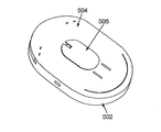
図5Aは、本発明の一実施例を示す。該実施例において、組み立てられた挿入装置は、トランスミッタ502、一実施例では使い捨てされ得るセンサ基部504、及びプローブトリガ506を有し得る。この実施例では、センサ及びセンサに対して高速推進力を供給する手段(図示せず)は、センサ基部504内に有され得る。一実施例では、センサは、皮膚上へとセンサ基部504の底部を配置すること、及び(圧入、スナップフィット、又は他の種類の配置において)トランスミッタ502の上部上を押すことによって挿入され得てプローブトリガ506を動かすか、あるいは、トリガされ得てセンサ基部504内部における高速推進力を供給する手段をセンサにぶつからせ、皮膚へと挿入する。
FIG. 5A shows one embodiment of the present invention. In the example, the assembled insertion device can have a
図5Aにおいて記載される実施例は、センサ基部504及びトランスミッタ502等である使い捨て又は再利用可能な部分を有し得る。故に、一実施例では、使い捨て装置は、最良可能なトランスミッタ構成要素502及び使い捨てセンサ基部504を有して与えられ得る。実施例では、他の電気構成要素(バッテリ、処理構成要素等)は、トランスミッタ構成要素502及び/又はセンサ基部504において与えられ得る。
The embodiment described in FIG. 5A may have disposable or reusable parts, such as
トランスミッタ構成要素は、関連付けられたセンサから電気信号を受けるよう、また、センサ信号に応じる外部電子監視ユニット等に対して更なる信号を送信するよう適合される電気ネットワークを有し得る本発明の一実施例に従った回路を有し得る。実施例では、電気ネットワークは、例えば該ネットワークがプリント回路基板、つなぎシステム、又は有線システム等を有するか否か、といった所望される構造的関係において多種の構成要素を有し得る。一実施例では、信号伝達は、RF通信等である電磁波を有して無線で発生し得るか、あるいはデータは、誘導結合を使用して読み込まれ得る。他の実施例では、伝達は、有線であるいは他の直接接続を介してなされ得る。 The transmitter component may have an electrical network adapted to receive an electrical signal from an associated sensor and to transmit further signals to an external electronic monitoring unit or the like that is responsive to the sensor signal. It may have a circuit according to the embodiment. In an embodiment, an electrical network may have a variety of components in a desired structural relationship, such as whether the network has a printed circuit board, a tether system, a wired system, or the like. In one embodiment, signaling can occur wirelessly with electromagnetic waves, such as RF communications, or data can be read using inductive coupling. In other embodiments, the communication can be done in a wired or other direct connection.
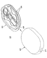
図5Bにおいて分解されて示される本発明の一実施例では、検出装置500は、トランスミッタ502をセンサ基部504上の溝506へと摺動することによって、組み立てられ得る。センサ基部504上の溝506は、センサ基部504及びトランスミッタ502を共に位置合わせして固定する。一実施例では、ロッキングラッチ508は、更なる固定を与えるよう、ロッキングエッジ510に対して固定する。
In one embodiment of the invention, shown exploded in FIG. 5B, the
一実施例では、トランスミッタは、再利用され得、センサ基部は、1回のみ使用されて廃棄されるよう適合され得る。他の実施例では、センサ基部及びトランスミッタはいずれも、再利用され得る。更に他の実施例では、いずれも廃棄されるよう適合され得る。 In one example, the transmitter can be reused and the sensor base can be adapted to be used and discarded only once. In other embodiments, both the sensor base and the transmitter can be reused. In still other embodiments, any can be adapted to be discarded.
本発明の実施例では、ハンドツールは、トランスミッタ及びセンサ基部を共に組み立てるよう使用され得る。ハンドツールは、まずトランスミッタをハンドツール上において上下逆に置くことによって使用され得る。センサ基部は、センサ基部の下部に沿って適所に位置付けられるバッキングカード及びテープストリップ、並びに対向する面にわたって保護用バブルキャップを備えられ得る。バブルキャップは、センサ基部から取り除かれ得、センサ基部は、ハンドツールの摺動部材上へと配置され得る。バッキングカードは、ハンドツール内においてセンサを位置合わせするよう使用され得る。次に、摺動部材は、トランスミッタにわたって押され得、トランスミッタ及びセンサ基部を共にスナッピングする。他の一実施例では、ハンドツールは、摺動部材ではなく、共にヒンジで動く2つの構成要素を有し得る。組立て後、バッキングカードは、取り除かれ得、ツールは、患者の身体上に装置を位置付けるよう使用され得る。実施例では、ツールを押すことによって、トリガは動き得、注射始動装置(injection activation device)を始動させ、センサが患者に挿入され得る。ハンドツールは、解放タブを締め付けることによって解放され得る。多くの異なるハンドツールの実施例が利用され得ること、又は実施例によってはハンドツールが使用され得ないことは、当業者には明らかである。 In embodiments of the present invention, the hand tool can be used to assemble the transmitter and sensor base together. The hand tool can be used by first placing the transmitter upside down on the hand tool. The sensor base may be provided with a backing card and tape strip positioned in place along the bottom of the sensor base, and a protective bubble cap over the opposing surfaces. The bubble cap can be removed from the sensor base, and the sensor base can be placed on the sliding member of the hand tool. The backing card can be used to align the sensor within the hand tool. The sliding member can then be pushed across the transmitter, snapping the transmitter and sensor base together. In another embodiment, the hand tool may have two components that move together with a hinge rather than a sliding member. After assembly, the backing card can be removed and the tool can be used to position the device on the patient's body. In an embodiment, by pressing the tool, the trigger can move, trigger an injection activation device, and a sensor can be inserted into the patient. The hand tool can be released by tightening the release tab. It will be apparent to those skilled in the art that many different hand tool embodiments may be utilized, or in some embodiments, hand tools may not be used.
複数の実施例では、高速推進力を供給する手段は、センサ基部に対して取り付けられ得る。他の実施例では、高速推進力を供給する手段は、センサ基部又はトランスミッタの一部ではない別個のハンドルに存在し得る。かかるハンドルの詳細は、米国特許出願番号第11/468,673号明細書において見られ得る。該文献は、トロカールも用いてセンサを挿入するよう推進力を与えるためにハンドルを使用する装置を記載する。本発明がトロカール又は関連する装置を使用することなくセンサを挿入する方法及び装置を有するが、ハンドルを有する該特許文献からの詳細は、本発明の多種の実施例に拡大適用され得る。 In embodiments, the means for supplying high speed propulsion can be attached to the sensor base. In other embodiments, the means for providing high speed propulsion may be in a separate handle that is not part of the sensor base or transmitter. Details of such a handle can be found in US patent application Ser. No. 11 / 468,673. The document describes a device that uses a handle to provide thrust to insert a sensor also using a trocar. Although the present invention has a method and apparatus for inserting a sensor without the use of a trocar or related device, details from the patent literature having a handle can be extended to various embodiments of the present invention.
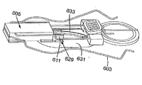
図6Aは、本発明の実施例に従ったセンサ基部600の構成要素を示す。湾曲した誘導構造601は、湾曲プローブ(図示せず)の上方端部を収容し得るスライダ605を介して挿入スプリング603に対して結合され得る。リード線607及び609は、電気接点をなすようセンサに対してはんだ付けされ得る。故に、スライダ605は、インサート成形に対して筐体を与え得、それによって末端を密封し、露出されたプローブに対する保護を与える。
FIG. 6A shows components of
挿入スプリング603は、製造中に取り付けられ得、スライダ605の最も外方の端部にわたって引き戻され得る。スライダ605は、2つのビーム611(一方のみを図示)によって前方に動かないようにされ得る。該ビームは、スライダ605から突出し、センサ基部600の基部表面615における矩形ホール613のエッジと係合する。このようにして、挿入スプリング603は、位置エネルギを保持し、スライダ605は、固定されたままにされ得る。
The
バッテリリード線617及び619は、例えば、バッテリ621に対してスポット溶接され得、バッテリ621は、ポッティング化合物(a potting compound)(図示せず)又は他の適切な固定化合物又は機械的手段を使用して適所に固定され得る。全ての4つのリード線607,609,617及び619は、コネクタ組立体625へとインサート成形され得る小型ワイヤスプリング623に対して取り付けられ得る。軟質ゴムガスケット627は、コネクタ組立体625の周辺に対して取り付けられ得、トランスミッタ(図示せず)が適所に固定され次第、トランスミッタ上における対応する接触パッドを密封する。コネクタ組立体625の接続面は、接触及び密封の特性が接合中に干渉しないよう、また、全接合力がトランスミッタ及びセンサ基部600を外すよう作用しないよう、角度を有する(on an angle)。
Battery leads 617 and 619 can be spot welded to, for example,
図6Bは、センサ基部600の複数の化合物の分解図である。この図では、誘導構造601は、トリガ631のライザー629及び露出プローブ633を省略され得る。本発明のこの実施例では、ライザー629は、上方に押し上げられ得る。これは同様に、2つの矩形ビーム611を上方に押し上げ得、該ビームが矩形ホール613の前方エッジ(図6A参照)に対して摺動させ得、ライザー629は開放され得る。開放されると、挿入スプリング603は、もはや抵抗を有し得ず、スライダ605を迅速に前進させ得る。そのようにする際、湾曲プローブ633は、湾曲誘導構造を通過し、センサ基部における開口(図示せず)を部分的に通過し、その後患者の皮膚へと挿入され得る。
FIG. 6B is an exploded view of a plurality of compounds in the
本発明のこの実施例では、トリガ631は、患者の皮膚上に装置を配置すること、及び下方向の圧力を適用することによって始動され得、トリガ631及びライザー629は装置に対して上方に上げられる。
In this embodiment of the invention, the
図6Cは、センサ基部600の断面図である。ここでは、トリガ631は、より明らかに図示される。トリガ631の上部上における湾曲特性は、挿入前にプローブ633を適所に維持し得、挿入中に湾曲プローブ633を案内する支援をする。トリガ631と基部表面615との間におけるギャップ635は、トリガ631が挿入中に押し上げられる際に、閉鎖し得る。
FIG. 6C is a cross-sectional view of
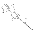
図7Aは、本発明の一実施例に従ったプローブガイドのコンセプトを示す。センサ701は、恒久的に取り付けられた上部ガイド703を有して図示される。本発明の一実施例では、上部ガイド703は、センサ701上へとインサート成形され得る。他の実施例では、上部ガイド703は、接着によって取り付けられ得る。他の実施例では、上部ガイド703は、超音波溶接され得る。下方端部ガイド705は、装置の筐体本体(図示せず)の一部であり得る。挿入時、センサ701は、筐体本体の成形特徴であり得る下方端部ガイド705内において摺動する。他の実施例では、下方端部ガイド705は、製造中に、筐体本体に対して接着される別個の部分であり得る。
FIG. 7A shows the concept of a probe guide according to one embodiment of the present invention. The
下方端部ガイド705は、センサ701が皮膚に対して90度ではない角度において皮膚へと挿入され得るよう、角度を付けられ得る。本発明の他の実施例では、センサ701は、90度を含む0−90度の他の角度において挿入され得る。
The
中央サボットガイド707は、変動性であり得、センサ701が皮膚へと挿入される際にセンサ701上において略中心に位置決めされたままにされ得る。言い換えれば、本発明の一実施例では、中央サボットガイド707は、センサ701又は挿入装置のいずれにも接着され得ない。中央サボットガイド707は、挿入時のセンサ701のバックリングを防ぎ得る。図7中の全ての構成要素は、センサ701が挿入されたあとに、装置と共に残り得る。
The
図7A中の誘導のコンセプトは、3つのガイドを有して図示されるが、3つより多いガイド又は3つより少ないガイドは、センサを案内してバックリングを防ぐよう用いられ得る、ことが当業者によって理解される。図7中の誘導コンセプトは円筒形のガイドを有して図示されるが、矩形の形状を制限的ではなく有する他の形状が用いられ得ることは、当業者によって理解される。多種の実施例において、ガイドは、誘導構造の形状及び寸法を収容するよう形成及び寸法取りされ得る。 Although the guidance concept in FIG. 7A is illustrated with three guides, more or less than three guides can be used to guide the sensor to prevent buckling. As understood by those skilled in the art. Although the guidance concept in FIG. 7 is illustrated with a cylindrical guide, it will be appreciated by those skilled in the art that other shapes having a rectangular shape without limitation can be used. In various embodiments, the guide can be shaped and dimensioned to accommodate the shape and dimensions of the guide structure.
図7A中に示されるガイドが多種のプラスチック又は金属を制限的ではなく有する他の材料から作られ得ることは、当業者によって理解される。 It will be appreciated by those skilled in the art that the guide shown in FIG. 7A can be made from other materials having various types of plastics or metals without limitation.
本発明の複数の実施例において、中央ガイドは、挿入中に容易につぶれ(collapse)得、且つ圧縮されると実質的に弾性を有さない、開放セルフォームプラスチックを有して作られ得る。 In embodiments of the present invention, the central guide can be made with an open cell foam plastic that can easily collapse during insertion and that is substantially inelastic when compressed.
他の実施例では、中央ガイドは、プローブを案内して挿入中のバックリングを防ぐ役割を有し得る中央ホールを有するプラスチックの螺旋を有し得る。該螺旋は、挿入中につぶれ得、圧縮される際に大変僅かな空間を占める。螺旋は、センサの挿入時に装置の本体内に残り得る。プラスチックの螺旋の製造は、成形すること又はロッティーニパスタ押出機に類似する装置を用いることによって、達成され得る。 In other embodiments, the central guide may have a plastic helix with a central hole that may serve to guide the probe and prevent buckling during insertion. The helix can collapse during insertion and occupies very little space when compressed. The helix can remain in the body of the device upon sensor insertion. The production of a plastic helix can be achieved by molding or by using an apparatus similar to a Rottini Pasta extruder.
本発明の他の実施例では、中央ガイドは、各々が中央ホールを有する一連の薄いプラスチックディスクによって置き換えられ得る。ディスクは、プローブを案内し得、挿入中のバックリングを防ぎ得る。挿入時、ディスクは、互いの上方で閉じ得(may close upon each other)、圧縮される際に大変僅かな空間を取り得る。本発明の多種の実施例では、ディスクは、薄いプラスチックシートから成形又はスタンプされ得る。 In another embodiment of the invention, the central guide can be replaced by a series of thin plastic disks each having a central hole. The disc can guide the probe and prevent buckling during insertion. When inserted, the discs may close close each other and take up very little space when compressed. In various embodiments of the invention, the disc can be molded or stamped from a thin plastic sheet.
図7Bに示される本発明の実施例では、上部ガイド709及び中央ガイド711は、センサ701に対する電気的接続を作ること、並びに、ガイドセンサ701を支援し、挿入中のバックリングを防ぐことを容易にし得る。これらの実施例では、ガイドは、複数の適切な金属を有する適切な導電性材料を有して作られ得る。一実施例では、上部ガイド709は、センサの露出されたコア(図示せず)に対してはんだ付けされ得、中央ガイド711は、溝713を介して銀クラッディング(図示せず)にはんだ付けされ得る。センサ701に対して上部ガイド709をはんだ付けすることは、センサ701に対する恒久的な取付けをもたらし得、高速推進力を適用する機構(図示せず)が挿入中に上部ガイド709に対して直接作用するようにし得る。
In the embodiment of the present invention shown in FIG. 7B, the
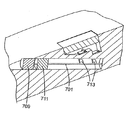
これより参照される図7Cは、挿入装置へと配置された図7Bのセンサ及びガイド設計の一実施例の断面図である。電気接点は、装置の本体へと組み込まれている一式のリーフスプリング接点713を用いることによって、装置とガイド709及び711との間において作られ得る。接点は、挿入時に、センサ701の移動の端部近くにおいて作られ得る。他の実施例では、電気接点は、上部と中央ガイド709及び711との間において夫々センサ701から離れて整列される(dressed)はんだ付けされたワイヤによって作られ得る。
Reference is now made to FIG. 7C, which is a cross-sectional view of one embodiment of the sensor and guide design of FIG. 7B placed into the insertion device. Electrical contacts can be made between the device and guides 709 and 711 by using a set of
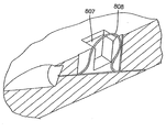
図8は、本発明の一実施例に従った挿入装置の底部の断面図である。センサ801は、弓状であり、装置の本体内において抑制される(restrained)弓状センサ801のジョブ湾曲は、露出された開口807を僅かに出て延在し得る。図8に示される通り、露出開口807は、装置の底部表面(皮膚上へと配置されるよう適合される表面)上に位置付けられる。装置は、患者の皮膚(図示せず)に対して配置され得、押し下げられ得る。力は、
弓状センサ801の上部に対して加えられ得、センサ801を真っ直ぐにするよう押し、センサ801が皮膚に入るよう、センサ801の近位先端/端部を十分な圧力を有して皮膚と接触するよう押し進める。センサ801は、コア材料を有し得、該コア材料は、真っ直ぐにされる際に高速推進力を生成するよう、弓状にされる際に十分な量のエネルギを格納するために十分な弾性特性を有する。
FIG. 8 is a cross-sectional view of the bottom of the insertion device according to one embodiment of the present invention. The sensor 801 is arcuate and the job curvature of the arcuate sensor 801 that is restrained within the body of the device may extend slightly out of the exposed
Can be applied to the top of the arcuate sensor 801 and pushes the sensor 801 straight to bring the proximal tip / end of the sensor 801 into contact with the skin with sufficient pressure so that the sensor 801 enters the skin Push to do. The sensor 801 can have a core material that is elastic enough to store a sufficient amount of energy when bowed to produce a high speed propulsion when straightened. Has characteristics.
多種の実施例では、図9Aの直接駆動直線ソレノイドアクチュエータ設計が取り入れられ得、センサに対して高速推進力を与えるようにする。これらの実施例では、ソレノイド901は、支持構造909を使用して装置の主要部分に対して結合され得る。支持構造909は、中空のコアを有する円筒形部材907を有する。ソレノイドシャフト903は、挿入ロッドとなるよう延在され得、センサの端部(図示せず)に対して直接衝突を与え、且つ高速推進力を与える。一実施例では、ソレノイドシャフト903は、円筒形部材907において部分的に位置付けられ得る。電力がソレノイド901に対して与えられる際、シャフト903は、挿入に対してセンサに高速推進力を与えるよう円筒形部材907を通って移動し得る。挿入後、円筒形部材907とシャフトストップ911との間において位置付けられる伸縮スプリング905は、シャフトをその挿入前の位置に戻し得る。
In various embodiments, the direct drive linear solenoid actuator design of FIG. 9A can be incorporated to provide high speed thrust to the sensor. In these embodiments, the
多種の実施例では、図9B中の回転ソレノイドアクチュエータ設計は、センサに対してこうそくしを与えるよう用いられ得る。かかる実施例では、回転ソレノイド951は、装置の本体部分に対して結合され得、支持構造967を使用する。アーム953は、ソレノイドの回転プレート957に対して取り付けられ得、アームの遠端は、穴あけされ、それ自体の上で後方に曲げられ得、ロッド955の上方端部に対して取り付けられるピン959を係合するよう開口を与える。電力がソレノイド951に対して与えられると、ソレノイドは、(図9Bにおける方向で)時計方向に周り、回転プレート957を回転させ、ピン959を直線ガイドスロット961に沿って動かし得る。ピン959の直線動作は、関連付けられるロッド955が装置の筐体構造の一部である中空の円筒形部材965を通って直線方向に動くようにし得る。ロッド955は、センサの端部(図示せず)に衝突し、センサの挿入に対する高速推進力を与え得る。
In various embodiments, the rotary solenoid actuator design in FIG. 9B can be used to provide a candle for the sensor. In such an embodiment, the
多少の実施例では、ロッドは、電力がソレノイドから除去される際にその本来の位置まで戻り得る。実施例では、スプリングは、製造者によってソレノイドへと組み入れられ得、電力が除去されると静止位置まで確実に戻るようにされる。 In some embodiments, the rod may return to its original position when power is removed from the solenoid. In an embodiment, the spring can be incorporated into the solenoid by the manufacturer to ensure that it returns to the rest position when power is removed.
ソレノイドを利用する本発明の実施例が図9A及び9B中の構造に制限されないことは、当業者によって理解される。例えば、図9B中の回転ソレノイドの実施例は、回転プレートに対して接続される回転アームではなくカム表面を組み入れ得る。図9A中に示される直線ソレノイドアクチュエータを使用する実施例は、図9A中に示される細長いソレノイドを利用するのではなくセンサの端部に衝突するよう多種の構成における中間構成要素を組み入れ得る。 It will be appreciated by those skilled in the art that embodiments of the present invention that utilize solenoids are not limited to the structure in FIGS. 9A and 9B. For example, the rotary solenoid embodiment in FIG. 9B may incorporate a cam surface rather than a rotating arm connected to a rotating plate. The embodiment using the linear solenoid actuator shown in FIG. 9A may incorporate intermediate components in a variety of configurations to impact the end of the sensor rather than utilizing the elongate solenoid shown in FIG. 9A.
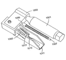
図10は、CO2カートリッジを用いる本発明の一実施例を示す。図示される通り、CO2カートリッジ1001のヘッド部は、マニホールド1003におけるホールへと配置され得、CO2カートリッジ1001の後方のナットは締められ、中空ピン(図示せず)がCO2カートリッジ1001を穿通するマニホールドへとより深くCO2カートリッジ1001が動くようにし、圧縮CO2がシステムに入り得るようにする。内部マニホールドチャンバは2つある(図示せず)。一方のチャンバは、CO2カートリッジ1001に対して接続し、他方は中空ピン1009に対して接続する。バルブを搭載するスプリング(図示せず)は、それらの間に位置決めされ得、カートリッジ1001及びその関連付けられるマニホールドチャンバからの圧力を最初に阻止する(hold back)。スプリングを搭載した撃針(firing pin)1007がバルブヘッド部1005を打つようにされる際、内部バルブ(図示せず)は一時的に開き、ある量のガスが、CO2カートリッジに関連付けられるマニホールドチャンバから中空管1009に関連付けられるマニホールドチャンバへと流れ得る。ガスは続いて、中空管1009に入り得、ロッド1011を前方に進ませ、挿入に対してセンサ(図示せず)にぶつからせる。ロッド1011が移動の端部に近付く際、排気口1013は、CO2が逃げ得るよう中空管1009の端部と過ぎて移動し得る。伸縮スプリング1015は、挿入後にロッド1011を動かし元の位置に戻すよう、用いられ得る。
FIG. 10 shows an embodiment of the present invention using a CO2 cartridge. As shown, the head of the
空気ポンプを用いる本発明の一実施例は、図11の断面図において示される。図11中に示される実施例は、前述されたCO2カートリッジの実施例におけるものと同様のマニホールドシステムを用い得る。マニホールドは、筐体構造1104に入れられる。レバーアーム1101が引き上げられる際、空気は、一方向バルブ(図示せず)を介してピストン1105に関連付けられるマニホールドチャンバへと吸引され得る。レバーアーム1101を押し下げることで、関連付けられるマニホールドへと進められ得るピストン1105のシャフトに対して結合されるリンク1103を動かす。マニホールドへのピストン1105の動作は、レバーアーム1101の上方ストロークにおいて関連付けられたマニホールドチャンバへと吸引されている空気を圧縮し得る。撃針1109がバルブヘッド部1111にぶつかるようにされる際、内部バルブ(図示せず)は一時的に開放し、圧縮空気は、ピストン1105と関連付けられたマニホールドチャンバから中空管1113に関連付けられるマニホールドチャンバへと動き得る。続いてガスは、中空管1113に入り得、ロッド1115を前進させて挿入に対してセンサ(図示せず)にぶつからせる。ロッド1115が移動の端部に近付く際、ロッド上の排気口(図示せず)は、中空管1113の端部を過ぎて移動し得、圧縮ガスが逃げ得るようにする。伸縮スプリング1117は、挿入後にロッド1115を動かしてその元の位置まで戻すよう、用いられ得る。
One embodiment of the present invention using an air pump is shown in the cross-sectional view of FIG. The embodiment shown in FIG. 11 may use a manifold system similar to that in the CO2 cartridge embodiment described above. The manifold is placed in the
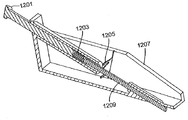
図12は、機械的スプリングを用いる本発明に従った一実施例を示す。この実施例では、弓状スプリング1205は、最初にボタン1201に向かって上方に弓状にされ得、ロッド1209の長さに沿って分かれるアクチュエータフレーム(actuator frame 1207 part way along the length of rod)へと配置され得る。ボタン1201は、押される場合に、弓状スプリング1205に対してぜんまい(power spring)1203を圧縮し得る一方、弓状スプリング1205におけるカットアウトは、ロッド1209のヘッド部が前進することを防ぐよう、ロッド1209へとスロットカットを係合させ得る。他の実施例では、外側リッジは、ロッド1209上においてスロットの代わりに用いられ得る。
FIG. 12 shows an embodiment according to the invention using a mechanical spring. In this embodiment, the
所定の力において、弓状スプリング1205は、「オイル缶(oil can)」効果を示し得、その湾曲は、向きを即座に反転させ得る。この作用は、ロッド1209をリッジカットから弓状スプリング1205へと解放し、ロッド1209は、挿入に対する高速推進力を有してセンサ(図示せず)にぶつかり得るぜんまい1203において作られる力によって、前方に駆動され得る。
At a given force, the
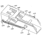
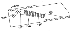
図13Aは、本発明の実施例に従った機械的スプリングを示す。スライダ1301は、支持構造1303の遠端まで引き戻され得、ピン1313によって支持されるスプリング1305において張力をもたらす。これより参照する図13Bは、機械的スプリングアクチュエータの断面図であり、スライダ1301は、ロッド1315の上部において傾斜された表面に寄りかかる傾斜された機構1317を有する。スライダ1301は、トリガ機構(図示せず)によって適所に維持され得る。ロッド1315は、各端部が支持構造1303の2つの傾斜スロット1309(図13A参照)内にあるピン1307に対して取り付けられ得る。トリガがスライダ1301を解放する際、スライダは、前進してロッド1315を動かし得、ピン1307によりスロット1309に対して平行である経路において動くようにする。続いてロッド1315は、挿入に対して高速推進力を供給するセンサ(図示せず)に衝突し得る。ロッド1314の移動の端部に向かってその傾斜上部機構は、スライダ1301の対応する傾斜機構から滑り落ち得、伸縮スプリング1311によって与えられる力を使用してロッドがその静止位置まで戻るようにする。スライダ1301は、再度引き戻される際、ロッドの上方端部から出て上方向に方向付けるカム表面(図示せず)に沿って乗り得、その後方に再度戻り、次の発射(firing)に対して準備する。
FIG. 13A shows a mechanical spring according to an embodiment of the present invention. The
図14は、機械的スプリング衝突装置の断面図である。該装置は、本発明の一実施例に従った挿入に対してセンサに高速推進力を与えるよう用いられる。ボタン1401が押される際、トリガアーム1403は、前方に駆動され得る。トリガアーム1403の対向する端部における小さな剪断部材1405は、撃針1407の上方端部において最初に係合され得、ロッド1411から撃針1407を引き離し、また、撃針1409が格納されたエネルギを圧縮及び増大するようにする。剪断部がその移動端部に向かって動く際、撃針1407は、夫々の移動方向の角度における違いにより、剪断部から滑り落ち得る。この時点で、撃針1407は、圧縮された撃針1409によって供給される力を有して前進し得、ロッド1411に衝突し、またロッドがセンサ(図示せず)に衝突して挿入に対する高速推進力を供給するようにさせる。
FIG. 14 is a cross-sectional view of a mechanical spring collision device. The device is used to provide a high speed thrust to the sensor for insertion according to one embodiment of the present invention. When the button 1401 is pressed, the
続いて、トリガアーム1403は、伸縮スプリング1413によって供給される力を有してその静止位置に向かって後進し得る。また、ロッド1411は、伸縮スプリング1413によって供給される力を有してその静止位置にまで後進し得る。剪断部材が撃針1407の上方端部にわたって通過する際、剪断部は、撃針1407の上方端部をクリアにするよう回転し、スプリング1415は、剪断部を回転させて次の挿入に対して準備するよう適所に戻す。
Subsequently, the
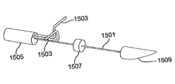
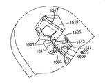
図15Aは、本発明の一実施例に従うワイヤリングのスキームを示す。センサ1501は、プラスチック底部ガイド1509及びプラスチック中央ガイド1507を有して図示される。リードワイヤ1503は、一実施例では、センサ1501に対してはんだ付けされ得、続いて上方ガイド1505へとインサート成形され得る。これより参照される図15Bにおいて、リードワイヤ1503の対向する端部は、装置の本体における接点1511に対してはんだ付けされ得る。誘導構造における開放溝1513は、センサ挿入中に、遮られないリードワイヤ1503の運動を可能にし得る。
FIG. 15A shows a wiring scheme according to one embodiment of the present invention.
挿入に先立ち、パッド1515は、ピン1521をレセプタクル1523へと部分的に配置することによって装置に対して部分的に取り付けられ得る。センサの挿入時、ピン1521は、レセプタクル1523へと完全に押圧され得、パッド1515がその最終位置へと押される際、短絡バー1517をバッテリパッド1525(一方のみを図示)に対して接触させ得る。このようにして、短絡バー1517は、装置の電力回路を完成させてそれをオンにする役割を有する。
Prior to insertion, the
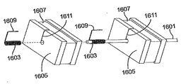
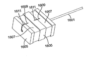
図16A及び16Bは、本発明の一実施例に従うセンサ電気終端組立体(sensor electrical termination assembly)を示す。図16Aは、実施例の分解図を示す。センサ1601は、センサ1601の上方導電性領域にわたって位置付けられる一式の斜めにされたコイルスプリング1603と適合され得る。2つの小さな矩形の筐体1605は、スプリングの上方に位置付けられ得、シート金属の2つの矩形の部分1607は、矩形の筐体1605における対応する溝へと配置され得る。図16Bを参照すると、斜めにされたコイルスプリング1603から延在する2つのリード線1609は、矩形筐体1605におけるスロット1611を介して与えられ得、シート金属の2つの部分1607上へとスポット溶接され得る。センサの挿入時に、この終端組立体は、挿入流路(図示せず)を下方に動かされる。挿入流路の底部において、矩形のシート金属1607は、流路(図示せず)から突出する2つの形成されたスプリング部材と接触し得る。
16A and 16B show a sensor electrical termination assembly according to one embodiment of the present invention. FIG. 16A shows an exploded view of the example.
他のアプローチは、2つの斜めにされたコイルスプリングの下方の向きを反転させ、リード線がスプリングの下方端部から出るようにする、ことである。そのようにして、組立体は、密封された接続を形成するよう矩形筐体へとインサート成形され得る。 Another approach is to reverse the downward orientation of the two angled coil springs so that the lead exits from the lower end of the spring. As such, the assembly can be insert molded into a rectangular housing to form a sealed connection.
他の実施例は、挿入流路の底部において終端組立体を事前に位置付けることを有する。該実施例では、センサは、組立体を通って移動し得、挿入時にスプリングと電気的に接触し得る。 Another embodiment includes prepositioning the termination assembly at the bottom of the insertion channel. In the example, the sensor can move through the assembly and can be in electrical contact with the spring upon insertion.
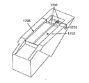
図17A及び17Bは、本発明の一実施例に従うペーパー誘導構造(paper guidance structure)を示す。図17Aに示される通り、ペーパー1703は、矩形のスロット1705内部及びセンサ1701の上方に配置され得る。ペーパー1703は、挿入に先立ちペーパー1703を固定するよう、また挿入中にガイドセンサ1701を案内するよう、使用され得る。挿入に先立ち、センサ1701は、例えばセンサ1701の直径の半分の深さにおいて、溝1711(図17B中で可視)に置かれ得る。
Figures 17A and 17B illustrate a paper guidance structure according to one embodiment of the present invention. As shown in FIG. 17A, the
図17Bを参照すると、注射始動装置(図示せず)は、センサ1701の上方端部を押し得、挿入中に矩形のスロット1705内を動き得る。動く際、注射始動装置は、スロット1711に沿ってペーパー1703を分け得、センサ1701が挿入される際にペーパーの裂け目1709を作る。挿入時に、センサ1701の導電性領域は、リーフスプリング1707と接触史得、装置に対してセンサ1701を電気的に結合させる。
Referring to FIG. 17B, an injection trigger (not shown) can push the upper end of
他の実施例では、薄いプラスチックのカバーリング等である他の同様な材料は、ペーパーを代替し得る。 In other embodiments, other similar materials, such as thin plastic coverings, may replace the paper.
本発明の一実施例では、更なる構成要素は、挿入装置に対して結合し得る(例えば、挿入装置に対してスナップ留めされ得るか、ワイヤ接続され得るか、無線通信し得る)1つ又はそれより多い別個のモジュールにおいて収容され得る。例えば、別個のモジュールは、メモリ構成要素、バッテリ構成要素、トランスミッタ、レシーバ、トランシーバ、プロセッサ、及び/又はディスプレイ構成要素を有し得る。 In one embodiment of the invention, one or more additional components may be coupled to the insertion device (eg, may be snapped to the insertion device, wired, or wirelessly communicated). It can be accommodated in more separate modules. For example, a separate module may have a memory component, a battery component, a transmitter, a receiver, a transceiver, a processor, and / or a display component.
本発明の一実施例では、実質的に均等な断面を有するセンサは、利用され得る。あるいは、本発明の一実施例では、多種の断面を有するセンサが使用され得る。実施例では、センサは、円筒形、四角形、矩形等であり得る。一実施例では、センサは、ワイヤタイプのセンサであり得る。一実施例では、センサは可撓性であり得る。 In one embodiment of the present invention, a sensor having a substantially uniform cross section may be utilized. Alternatively, in one embodiment of the present invention, sensors having various cross sections can be used. In embodiments, the sensor can be cylindrical, square, rectangular, etc. In one example, the sensor may be a wire type sensor. In one example, the sensor can be flexible.
望ましい実施例を説明するよう特定の実施例が図示及び説明されてきたが、同一の目的を達成すると予測される多種の他の及び/又は同等の実施例又は実施は、本発明の範囲から逸脱することなく図示及び説明される実施例の代替となり得る、ことが当業者によって理解される。当業者は、本発明に従った実施例が大変多種の方途において実施され得る、ことを容易に理解する。本願は、ここに記載される実施例の変形又は適合を包含するよう意図される。したがって、本発明に従った実施例が請求項及びそれと同等のものによってのみ制限されることは、明らかに意図されている。 While specific embodiments have been illustrated and described to illustrate the preferred embodiment, various other and / or equivalent embodiments or implementations that are expected to achieve the same objective are not within the scope of the invention. It will be understood by those skilled in the art that the embodiments shown and described may be substituted without being described. Those skilled in the art will readily appreciate that embodiments according to the present invention can be implemented in a very wide variety of ways. This application is intended to cover variations or adaptations of the embodiments described herein. Therefore, it is manifestly intended that embodiments in accordance with the present invention be limited only by the claims and the equivalents thereof.
本発明は、センサ、又は流体運搬構造、又は流体運搬構造センサの組合せ等である装置を例えば哺乳類の皮膚へと送る装置及び方法に係る。かかる装置により、センサは、針等である導入装置を使用することなく哺乳類の皮膚に入り得る。本発明の実施例に従う装置は、哺乳類の皮膚への取付けに対して筐体を有し、該筐体は、バイオセンサの遠位端部を受容する出口部、及び注射始動装置を有する。該注射始動装置は、哺乳類の皮膚に部分的に入るよう十分に早い速度を有して、検出装置を筐体内における第1の位置から出口部を介して第2の位置まで押し進める機構を有する。 The present invention relates to an apparatus and method for delivering a device, such as a sensor, or a fluid carrying structure, or a combination of fluid carrying structure sensors, to the skin of a mammal, for example. With such a device, the sensor can enter the skin of a mammal without the use of an introducer device, such as a needle. An apparatus according to an embodiment of the present invention has a housing for attachment to mammalian skin, the housing having an outlet for receiving the distal end of the biosensor and an injection triggering device. The injection triggering device has a mechanism that pushes the detection device from a first position in the housing to a second position through the outlet portion at a sufficiently high speed to partially enter the mammalian skin.
Claims (10)
前記挿入装置は、
前記可撓性の検体センサに対して軸方向支持を与えるよう適合され、また、使用時に前記皮膚に対して外部にあるよう適合される誘導構造であって、当該誘導構造は出口部を有する、誘導構造と、
前記誘導構造に関連付けられる注射始動装置であって、当該注射始動装置は、前記可撓性の検体センサに対して高速推進力を適用するよう適合される機構を有し、制御された衝撃及び駆動力が、前記可撓性の検体センサに適用され、前記可撓性の検体センサは、前記誘導構造を少なくとも部分的に通って、かつ、前記誘導構造とは独立して動き、かつ、前記出口部を少なくとも部分的に通過して、前記皮膚への前記可撓性の検体センサの挿入が引き起こされる、注射始動装置と、
を有し、
前記挿入装置は、前記皮膚への前記可撓性の検体センサの挿入を、剛性を有する及び/又は鋭利な導入装置無しで引き起こすよう構成される、
医療機器。 A medical device comprising a flexible analyte sensor and an insertion device for inserting the flexible analyte sensor into the skin,
The insertion device is
A guiding structure adapted to provide axial support to the flexible analyte sensor and adapted to be external to the skin in use, the guiding structure having an outlet portion; A guiding structure;
An injection starter associated with the guide structure, the injection starter having a mechanism adapted to apply a high speed propulsion force to the flexible analyte sensor for controlled impact and drive Force is applied to the flexible analyte sensor, the flexible analyte sensor moving at least partially through the guidance structure and independent of the guidance structure, and the outlet An injection triggering device that is at least partially passed through a section to cause insertion of the flexible analyte sensor into the skin;
Have
The insertion device is configured to cause insertion of the flexible analyte sensor into the skin without a rigid and / or sharp introducer;
Medical equipment.
請求項1に記載の医療機器。 The guidance structure further includes at least one guide member associated with the guidance structure, the at least one guide member is adapted to fit within the guidance structure, and the analyte sensor is the at least one guide member. Adapted to pass through the guide member,
The medical device according to claim 1.
前記筐体は、
前記注射始動装置であって、前記筐体内で少なくとも部分的に固定される注射始動装置と、
前記誘導構造と位置合わせされる開口であって、最初は前記筐体内に全体が収納される前記センサが、前記高速推進力の適用時に、前記筐体の前記開口及び前記誘導構造の両方を通過することができる、開口と、
を有する、
請求項1に記載の医療機器。 The insertion device further comprises a housing;
The housing is
The injection starter, wherein the injection starter is at least partially secured within the housing;
An opening that is aligned with the guiding structure, and initially the sensor is housed entirely within the housing, and passes through both the opening and the guiding structure of the housing when the high-speed propulsion is applied. Can with an opening,
Having
The medical device according to claim 1.
請求項1に記載の医療機器。 The guiding structure is a tube having a circular diameter;
The medical device according to claim 1.
前記少なくとも1つのガイド部材は、前記誘導構造の内部に合うよう適合される、
請求項1に記載の医療機器。 The insertion device further comprises at least one guide member associated with both the guiding structure and the analyte sensor;
The at least one guide member is adapted to fit within the guide structure;
The medical device according to claim 1.
請求項1に記載の医療機器。 Further comprising an electrical network coupled to the analyte sensor;
The medical device according to claim 1.
請求項1に記載の医療機器。 The guiding structure is a curved guiding structure;
The medical device according to claim 1.
請求項7に記載の医療機器。 The curved guiding structure is a curved hollow tube having a circular cross section;
The medical device according to claim 7.
挿入の間、前記センサによって形成される前記アークの前記半径の内側に少なくとも部分的に位置する、一部開放領域と、
を有する、請求項7に記載の医療機器。 The curved guiding structure, during insertion, an upper surface located at least partially outside the radius of the arc formed by the sensor;
A partially open region located at least partially inside the radius of the arc formed by the sensor during insertion;
The medical device according to claim 7, comprising:
Applications Claiming Priority (4)
| Application Number | Priority Date | Filing Date | Title |
|---|---|---|---|
| US73573205P | 2005-11-11 | 2005-11-11 | |
| US60/735,732 | 2005-11-11 | ||
| US11/558,394 | 2006-11-09 | ||
| US11/558,394 US20070173706A1 (en) | 2005-11-11 | 2006-11-09 | Method and apparatus for insertion of a sensor |
Related Parent Applications (1)
| Application Number | Title | Priority Date | Filing Date |
|---|---|---|---|
| JP2008540203A Division JP2009515595A (en) | 2005-11-11 | 2006-11-10 | Method and apparatus for sensor insertion |
Publications (1)
| Publication Number | Publication Date |
|---|---|
| JP2013144123A true JP2013144123A (en) | 2013-07-25 |
Family
ID=38049158
Family Applications (2)
| Application Number | Title | Priority Date | Filing Date |
|---|---|---|---|
| JP2008540203A Pending JP2009515595A (en) | 2005-11-11 | 2006-11-10 | Method and apparatus for sensor insertion |
| JP2013038650A Pending JP2013144123A (en) | 2005-11-11 | 2013-02-28 | Medical instrument |
Family Applications Before (1)
| Application Number | Title | Priority Date | Filing Date |
|---|---|---|---|
| JP2008540203A Pending JP2009515595A (en) | 2005-11-11 | 2006-11-10 | Method and apparatus for sensor insertion |
Country Status (6)
| Country | Link |
|---|---|
| US (1) | US20070173706A1 (en) |
| EP (1) | EP1945113A4 (en) |
| JP (2) | JP2009515595A (en) |
| CN (2) | CN101304697B (en) |
| CA (1) | CA2628444A1 (en) |
| WO (1) | WO2007058921A2 (en) |
Families Citing this family (211)
| Publication number | Priority date | Publication date | Assignee | Title |
|---|---|---|---|---|
| US7381184B2 (en) | 2002-11-05 | 2008-06-03 | Abbott Diabetes Care Inc. | Sensor inserter assembly |
| AU2003303597A1 (en) | 2002-12-31 | 2004-07-29 | Therasense, Inc. | Continuous glucose monitoring system and methods of use |
| US8771183B2 (en) | 2004-02-17 | 2014-07-08 | Abbott Diabetes Care Inc. | Method and system for providing data communication in continuous glucose monitoring and management system |
| US8066639B2 (en) | 2003-06-10 | 2011-11-29 | Abbott Diabetes Care Inc. | Glucose measuring device for use in personal area network |
| US7591801B2 (en) | 2004-02-26 | 2009-09-22 | Dexcom, Inc. | Integrated delivery device for continuous glucose sensor |
| US20190357827A1 (en) | 2003-08-01 | 2019-11-28 | Dexcom, Inc. | Analyte sensor |
| US8886273B2 (en) | 2003-08-01 | 2014-11-11 | Dexcom, Inc. | Analyte sensor |
| US8626257B2 (en) | 2003-08-01 | 2014-01-07 | Dexcom, Inc. | Analyte sensor |
| US7920906B2 (en) | 2005-03-10 | 2011-04-05 | Dexcom, Inc. | System and methods for processing analyte sensor data for sensor calibration |
| US7299082B2 (en) | 2003-10-31 | 2007-11-20 | Abbott Diabetes Care, Inc. | Method of calibrating an analyte-measurement device, and associated methods, devices and systems |
| USD914881S1 (en) | 2003-11-05 | 2021-03-30 | Abbott Diabetes Care Inc. | Analyte sensor electronic mount |
| US9247900B2 (en) | 2004-07-13 | 2016-02-02 | Dexcom, Inc. | Analyte sensor |
| US8532730B2 (en) | 2006-10-04 | 2013-09-10 | Dexcom, Inc. | Analyte sensor |
| US8364231B2 (en) | 2006-10-04 | 2013-01-29 | Dexcom, Inc. | Analyte sensor |
| US8364230B2 (en) | 2006-10-04 | 2013-01-29 | Dexcom, Inc. | Analyte sensor |
| US8425416B2 (en) | 2006-10-04 | 2013-04-23 | Dexcom, Inc. | Analyte sensor |
| US8425417B2 (en) | 2003-12-05 | 2013-04-23 | Dexcom, Inc. | Integrated device for continuous in vivo analyte detection and simultaneous control of an infusion device |
| WO2009048462A1 (en) | 2007-10-09 | 2009-04-16 | Dexcom, Inc. | Integrated insulin delivery system with continuous glucose sensor |
| US8808228B2 (en) | 2004-02-26 | 2014-08-19 | Dexcom, Inc. | Integrated medicament delivery device for use with continuous analyte sensor |
| WO2005119524A2 (en) | 2004-06-04 | 2005-12-15 | Therasense, Inc. | Diabetes care host-client architecture and data management system |
| US8989833B2 (en) | 2004-07-13 | 2015-03-24 | Dexcom, Inc. | Transcutaneous analyte sensor |
| US8886272B2 (en) | 2004-07-13 | 2014-11-11 | Dexcom, Inc. | Analyte sensor |
| US20070045902A1 (en) | 2004-07-13 | 2007-03-01 | Brauker James H | Analyte sensor |
| US7783333B2 (en) | 2004-07-13 | 2010-08-24 | Dexcom, Inc. | Transcutaneous medical device with variable stiffness |
| US8512243B2 (en) | 2005-09-30 | 2013-08-20 | Abbott Diabetes Care Inc. | Integrated introducer and transmitter assembly and methods of use |
| US9398882B2 (en) | 2005-09-30 | 2016-07-26 | Abbott Diabetes Care Inc. | Method and apparatus for providing analyte sensor and data processing device |
| US9743862B2 (en) | 2011-03-31 | 2017-08-29 | Abbott Diabetes Care Inc. | Systems and methods for transcutaneously implanting medical devices |
| US8613703B2 (en) | 2007-05-31 | 2013-12-24 | Abbott Diabetes Care Inc. | Insertion devices and methods |
| US7883464B2 (en) | 2005-09-30 | 2011-02-08 | Abbott Diabetes Care Inc. | Integrated transmitter unit and sensor introducer mechanism and methods of use |
| US8029441B2 (en) | 2006-02-28 | 2011-10-04 | Abbott Diabetes Care Inc. | Analyte sensor transmitter unit configuration for a data monitoring and management system |
| US7697967B2 (en) | 2005-12-28 | 2010-04-13 | Abbott Diabetes Care Inc. | Method and apparatus for providing analyte sensor insertion |
| US9351669B2 (en) | 2009-09-30 | 2016-05-31 | Abbott Diabetes Care Inc. | Interconnect for on-body analyte monitoring device |
| US9636450B2 (en) | 2007-02-19 | 2017-05-02 | Udo Hoss | Pump system modular components for delivering medication and analyte sensing at seperate insertion sites |
| US7731657B2 (en) | 2005-08-30 | 2010-06-08 | Abbott Diabetes Care Inc. | Analyte sensor introducer and methods of use |
| US10226207B2 (en) | 2004-12-29 | 2019-03-12 | Abbott Diabetes Care Inc. | Sensor inserter having introducer |
| US8571624B2 (en) | 2004-12-29 | 2013-10-29 | Abbott Diabetes Care Inc. | Method and apparatus for mounting a data transmission device in a communication system |
| US9572534B2 (en) | 2010-06-29 | 2017-02-21 | Abbott Diabetes Care Inc. | Devices, systems and methods for on-skin or on-body mounting of medical devices |
| US9788771B2 (en) | 2006-10-23 | 2017-10-17 | Abbott Diabetes Care Inc. | Variable speed sensor insertion devices and methods of use |
| US9259175B2 (en) | 2006-10-23 | 2016-02-16 | Abbott Diabetes Care, Inc. | Flexible patch for fluid delivery and monitoring body analytes |
| US8333714B2 (en) | 2006-09-10 | 2012-12-18 | Abbott Diabetes Care Inc. | Method and system for providing an integrated analyte sensor insertion device and data processing unit |
| US7545272B2 (en) | 2005-02-08 | 2009-06-09 | Therasense, Inc. | RF tag on test strips, test strip vials and boxes |
| US8112240B2 (en) | 2005-04-29 | 2012-02-07 | Abbott Diabetes Care Inc. | Method and apparatus for providing leak detection in data monitoring and management systems |
| CA2620586A1 (en) | 2005-08-31 | 2007-03-08 | Boris P. Kovatchev | Improving the accuracy of continuous glucose sensors |
| US9521968B2 (en) | 2005-09-30 | 2016-12-20 | Abbott Diabetes Care Inc. | Analyte sensor retention mechanism and methods of use |
| US8880138B2 (en) | 2005-09-30 | 2014-11-04 | Abbott Diabetes Care Inc. | Device for channeling fluid and methods of use |
| US7766829B2 (en) | 2005-11-04 | 2010-08-03 | Abbott Diabetes Care Inc. | Method and system for providing basal profile modification in analyte monitoring and management systems |
| US9615851B2 (en) * | 2005-11-11 | 2017-04-11 | Waveform Technologies, Inc. | Method and apparatus for insertion of a sensor |
| EP1968432A4 (en) | 2005-12-28 | 2009-10-21 | Abbott Diabetes Care Inc | Medical device insertion |
| US11298058B2 (en) | 2005-12-28 | 2022-04-12 | Abbott Diabetes Care Inc. | Method and apparatus for providing analyte sensor insertion |
| US7736310B2 (en) | 2006-01-30 | 2010-06-15 | Abbott Diabetes Care Inc. | On-body medical device securement |
| US7885698B2 (en) | 2006-02-28 | 2011-02-08 | Abbott Diabetes Care Inc. | Method and system for providing continuous calibration of implantable analyte sensors |
| US7826879B2 (en) | 2006-02-28 | 2010-11-02 | Abbott Diabetes Care Inc. | Analyte sensors and methods of use |
| US9392969B2 (en) | 2008-08-31 | 2016-07-19 | Abbott Diabetes Care Inc. | Closed loop control and signal attenuation detection |
| US7630748B2 (en) | 2006-10-25 | 2009-12-08 | Abbott Diabetes Care Inc. | Method and system for providing analyte monitoring |
| US7618369B2 (en) | 2006-10-02 | 2009-11-17 | Abbott Diabetes Care Inc. | Method and system for dynamically updating calibration parameters for an analyte sensor |
| US7620438B2 (en) | 2006-03-31 | 2009-11-17 | Abbott Diabetes Care Inc. | Method and system for powering an electronic device |
| US8374668B1 (en) | 2007-10-23 | 2013-02-12 | Abbott Diabetes Care Inc. | Analyte sensor with lag compensation |
| US8473022B2 (en) | 2008-01-31 | 2013-06-25 | Abbott Diabetes Care Inc. | Analyte sensor with time lag compensation |
| US8219173B2 (en) | 2008-09-30 | 2012-07-10 | Abbott Diabetes Care Inc. | Optimizing analyte sensor calibration |
| US7801582B2 (en) | 2006-03-31 | 2010-09-21 | Abbott Diabetes Care Inc. | Analyte monitoring and management system and methods therefor |
| US7653425B2 (en) | 2006-08-09 | 2010-01-26 | Abbott Diabetes Care Inc. | Method and system for providing calibration of an analyte sensor in an analyte monitoring system |
| US8346335B2 (en) | 2008-03-28 | 2013-01-01 | Abbott Diabetes Care Inc. | Analyte sensor calibration management |
| US9675290B2 (en) | 2012-10-30 | 2017-06-13 | Abbott Diabetes Care Inc. | Sensitivity calibration of in vivo sensors used to measure analyte concentration |
| US8224415B2 (en) | 2009-01-29 | 2012-07-17 | Abbott Diabetes Care Inc. | Method and device for providing offset model based calibration for analyte sensor |
| US8226891B2 (en) | 2006-03-31 | 2012-07-24 | Abbott Diabetes Care Inc. | Analyte monitoring devices and methods therefor |
| US8140312B2 (en) | 2007-05-14 | 2012-03-20 | Abbott Diabetes Care Inc. | Method and system for determining analyte levels |
| US8478557B2 (en) | 2009-07-31 | 2013-07-02 | Abbott Diabetes Care Inc. | Method and apparatus for providing analyte monitoring system calibration accuracy |
| WO2007143225A2 (en) | 2006-06-07 | 2007-12-13 | Abbott Diabetes Care, Inc. | Analyte monitoring system and method |
| US8275438B2 (en) | 2006-10-04 | 2012-09-25 | Dexcom, Inc. | Analyte sensor |
| US8478377B2 (en) | 2006-10-04 | 2013-07-02 | Dexcom, Inc. | Analyte sensor |
| US8447376B2 (en) | 2006-10-04 | 2013-05-21 | Dexcom, Inc. | Analyte sensor |
| US8562528B2 (en) | 2006-10-04 | 2013-10-22 | Dexcom, Inc. | Analyte sensor |
| US8298142B2 (en) | 2006-10-04 | 2012-10-30 | Dexcom, Inc. | Analyte sensor |
| US8449464B2 (en) | 2006-10-04 | 2013-05-28 | Dexcom, Inc. | Analyte sensor |
| AU2007308804A1 (en) | 2006-10-26 | 2008-05-02 | Abbott Diabetes Care, Inc. | Method, system and computer program product for real-time detection of sensitivity decline in analyte sensors |
| US8121857B2 (en) | 2007-02-15 | 2012-02-21 | Abbott Diabetes Care Inc. | Device and method for automatic data acquisition and/or detection |
| US20080199894A1 (en) | 2007-02-15 | 2008-08-21 | Abbott Diabetes Care, Inc. | Device and method for automatic data acquisition and/or detection |
| US8732188B2 (en) | 2007-02-18 | 2014-05-20 | Abbott Diabetes Care Inc. | Method and system for providing contextual based medication dosage determination |
| US8930203B2 (en) | 2007-02-18 | 2015-01-06 | Abbott Diabetes Care Inc. | Multi-function analyte test device and methods therefor |
| US8123686B2 (en) | 2007-03-01 | 2012-02-28 | Abbott Diabetes Care Inc. | Method and apparatus for providing rolling data in communication systems |
| CA2683959C (en) | 2007-04-14 | 2017-08-29 | Abbott Diabetes Care Inc. | Method and apparatus for providing data processing and control in medical communication system |
| WO2008130898A1 (en) | 2007-04-14 | 2008-10-30 | Abbott Diabetes Care, Inc. | Method and apparatus for providing data processing and control in medical communication system |
| EP2146622B1 (en) | 2007-04-14 | 2016-05-11 | Abbott Diabetes Care Inc. | Method and apparatus for providing dynamic multi-stage signal amplification in a medical device |
| ES2461090T3 (en) | 2007-04-14 | 2014-05-16 | Abbott Diabetes Care Inc. | Procedure and apparatus for providing data treatment and control in a medical communication system |
| CA2683930A1 (en) | 2007-04-14 | 2008-10-23 | Abbott Diabetes Care Inc. | Method and apparatus for providing data processing and control in medical communication system |
| WO2009096992A1 (en) | 2007-04-14 | 2009-08-06 | Abbott Diabetes Care, Inc. | Method and apparatus for providing data processing and control in medical communication system |
| US8461985B2 (en) | 2007-05-08 | 2013-06-11 | Abbott Diabetes Care Inc. | Analyte monitoring system and methods |
| US8665091B2 (en) | 2007-05-08 | 2014-03-04 | Abbott Diabetes Care Inc. | Method and device for determining elapsed sensor life |
| US7928850B2 (en) | 2007-05-08 | 2011-04-19 | Abbott Diabetes Care Inc. | Analyte monitoring system and methods |
| US8456301B2 (en) | 2007-05-08 | 2013-06-04 | Abbott Diabetes Care Inc. | Analyte monitoring system and methods |
| US8239166B2 (en) | 2007-05-14 | 2012-08-07 | Abbott Diabetes Care Inc. | Method and apparatus for providing data processing and control in a medical communication system |
| US8444560B2 (en) | 2007-05-14 | 2013-05-21 | Abbott Diabetes Care Inc. | Method and apparatus for providing data processing and control in a medical communication system |
| US8560038B2 (en) | 2007-05-14 | 2013-10-15 | Abbott Diabetes Care Inc. | Method and apparatus for providing data processing and control in a medical communication system |
| US9125548B2 (en) | 2007-05-14 | 2015-09-08 | Abbott Diabetes Care Inc. | Method and apparatus for providing data processing and control in a medical communication system |
| US8260558B2 (en) | 2007-05-14 | 2012-09-04 | Abbott Diabetes Care Inc. | Method and apparatus for providing data processing and control in a medical communication system |
| US10002233B2 (en) | 2007-05-14 | 2018-06-19 | Abbott Diabetes Care Inc. | Method and apparatus for providing data processing and control in a medical communication system |
| US8600681B2 (en) | 2007-05-14 | 2013-12-03 | Abbott Diabetes Care Inc. | Method and apparatus for providing data processing and control in a medical communication system |
| US7996158B2 (en) | 2007-05-14 | 2011-08-09 | Abbott Diabetes Care Inc. | Method and apparatus for providing data processing and control in a medical communication system |
| US8103471B2 (en) | 2007-05-14 | 2012-01-24 | Abbott Diabetes Care Inc. | Method and apparatus for providing data processing and control in a medical communication system |
| US20080306444A1 (en) | 2007-06-08 | 2008-12-11 | Dexcom, Inc. | Integrated medicament delivery device for use with continuous analyte sensor |
| CN103251414B (en) | 2007-06-21 | 2017-05-24 | 雅培糖尿病护理公司 | Device for detecting analyte level |
| EP2171031B1 (en) | 2007-06-21 | 2018-12-05 | Abbott Diabetes Care Inc. | Health management devices and methods |
| US8160900B2 (en) | 2007-06-29 | 2012-04-17 | Abbott Diabetes Care Inc. | Analyte monitoring and management device and method to analyze the frequency of user interaction with the device |
| US7768386B2 (en) | 2007-07-31 | 2010-08-03 | Abbott Diabetes Care Inc. | Method and apparatus for providing data processing and control in a medical communication system |
| US8834366B2 (en) | 2007-07-31 | 2014-09-16 | Abbott Diabetes Care Inc. | Method and apparatus for providing analyte sensor calibration |
| WO2009042810A2 (en) * | 2007-09-25 | 2009-04-02 | Isense Corporation | Method and apparatus for treating skin prior to biosensor insertion |
| US8216138B1 (en) | 2007-10-23 | 2012-07-10 | Abbott Diabetes Care Inc. | Correlation of alternative site blood and interstitial fluid glucose concentrations to venous glucose concentration |
| US8409093B2 (en) | 2007-10-23 | 2013-04-02 | Abbott Diabetes Care Inc. | Assessing measures of glycemic variability |
| US8377031B2 (en) | 2007-10-23 | 2013-02-19 | Abbott Diabetes Care Inc. | Closed loop control system with safety parameters and methods |
| US20090164239A1 (en) | 2007-12-19 | 2009-06-25 | Abbott Diabetes Care, Inc. | Dynamic Display Of Glucose Information |
| WO2009105709A1 (en) | 2008-02-21 | 2009-08-27 | Dexcom, Inc. | Systems and methods for processing, transmitting and displaying sensor data |
| BRPI0909361A2 (en) * | 2008-03-17 | 2015-09-29 | Isense Corp | analyte sensor subset and methods and apparatus for inserting an analyte sensor associated with it |
| US8396528B2 (en) | 2008-03-25 | 2013-03-12 | Dexcom, Inc. | Analyte sensor |
| US8252229B2 (en) | 2008-04-10 | 2012-08-28 | Abbott Diabetes Care Inc. | Method and system for sterilizing an analyte sensor |
| US8924159B2 (en) | 2008-05-30 | 2014-12-30 | Abbott Diabetes Care Inc. | Method and apparatus for providing glycemic control |
| US7826382B2 (en) | 2008-05-30 | 2010-11-02 | Abbott Diabetes Care Inc. | Close proximity communication device and methods |
| US8591410B2 (en) | 2008-05-30 | 2013-11-26 | Abbott Diabetes Care Inc. | Method and apparatus for providing glycemic control |
| US8876755B2 (en) | 2008-07-14 | 2014-11-04 | Abbott Diabetes Care Inc. | Closed loop control system interface and methods |
| US9943644B2 (en) | 2008-08-31 | 2018-04-17 | Abbott Diabetes Care Inc. | Closed loop control with reference measurement and methods thereof |
| US20100057040A1 (en) | 2008-08-31 | 2010-03-04 | Abbott Diabetes Care, Inc. | Robust Closed Loop Control And Methods |
| US8734422B2 (en) | 2008-08-31 | 2014-05-27 | Abbott Diabetes Care Inc. | Closed loop control with improved alarm functions |
| US8622988B2 (en) | 2008-08-31 | 2014-01-07 | Abbott Diabetes Care Inc. | Variable rate closed loop control and methods |
| US8986208B2 (en) | 2008-09-30 | 2015-03-24 | Abbott Diabetes Care Inc. | Analyte sensor sensitivity attenuation mitigation |
| DE502008003439D1 (en) * | 2008-10-02 | 2011-06-16 | Eyesense Ag | Implantation device for metabolite sensors |
| US9326707B2 (en) | 2008-11-10 | 2016-05-03 | Abbott Diabetes Care Inc. | Alarm characterization for analyte monitoring devices and systems |
| US8103456B2 (en) | 2009-01-29 | 2012-01-24 | Abbott Diabetes Care Inc. | Method and device for early signal attenuation detection using blood glucose measurements |
| US9402544B2 (en) | 2009-02-03 | 2016-08-02 | Abbott Diabetes Care Inc. | Analyte sensor and apparatus for insertion of the sensor |
| US20100198033A1 (en) * | 2009-02-05 | 2010-08-05 | Peter Krulevitch | Flexible indwelling biosensor, flexible indwelling biosensor insertion device, and related methods |
| US8497777B2 (en) | 2009-04-15 | 2013-07-30 | Abbott Diabetes Care Inc. | Analyte monitoring system having an alert |
| EP2419015A4 (en) | 2009-04-16 | 2014-08-20 | Abbott Diabetes Care Inc | Analyte sensor calibration management |
| WO2010127050A1 (en) | 2009-04-28 | 2010-11-04 | Abbott Diabetes Care Inc. | Error detection in critical repeating data in a wireless sensor system |
| WO2010127187A1 (en) | 2009-04-29 | 2010-11-04 | Abbott Diabetes Care Inc. | Method and system for providing data communication in continuous glucose monitoring and management system |
| US8483967B2 (en) | 2009-04-29 | 2013-07-09 | Abbott Diabetes Care Inc. | Method and system for providing real time analyte sensor calibration with retrospective backfill |
| US8597274B2 (en) | 2009-05-22 | 2013-12-03 | Abbott Diabetes Care Inc. | Usability features for integrated insulin delivery system |
| WO2010138856A1 (en) | 2009-05-29 | 2010-12-02 | Abbott Diabetes Care Inc. | Medical device antenna systems having external antenna configurations |
| US8613892B2 (en) | 2009-06-30 | 2013-12-24 | Abbott Diabetes Care Inc. | Analyte meter with a moveable head and methods of using the same |
| US10376213B2 (en) * | 2009-06-30 | 2019-08-13 | Waveform Technologies, Inc. | System, method and apparatus for sensor insertion |
| EP3689237B1 (en) | 2009-07-23 | 2021-05-19 | Abbott Diabetes Care, Inc. | Method of manufacturing and system for continuous analyte measurement |
| EP2473099A4 (en) | 2009-08-31 | 2015-01-14 | Abbott Diabetes Care Inc | ANALYTICAL SUBSTANCE MONITORING SYSTEM AND METHODS OF MANAGING ENERGY AND NOISE |
| EP4070727B1 (en) | 2009-08-31 | 2023-07-05 | Abbott Diabetes Care, Inc. | Displays for a medical device |
| JP5795584B2 (en) | 2009-08-31 | 2015-10-14 | アボット ダイアベティス ケア インコーポレイテッドAbbott Diabetes Care Inc. | Medical device |
| WO2011026147A1 (en) | 2009-08-31 | 2011-03-03 | Abbott Diabetes Care Inc. | Analyte signal processing device and methods |
| US9320461B2 (en) | 2009-09-29 | 2016-04-26 | Abbott Diabetes Care Inc. | Method and apparatus for providing notification function in analyte monitoring systems |
| EP2311374A1 (en) * | 2009-10-13 | 2011-04-20 | Roche Diagnostics GmbH | Apparatus for retrieving and analysing blood; coupling mechanism for lancets |
| WO2011053881A1 (en) | 2009-10-30 | 2011-05-05 | Abbott Diabetes Care Inc. | Method and apparatus for detecting false hypoglycemic conditions |
| USD924406S1 (en) | 2010-02-01 | 2021-07-06 | Abbott Diabetes Care Inc. | Analyte sensor inserter |
| WO2011112753A1 (en) | 2010-03-10 | 2011-09-15 | Abbott Diabetes Care Inc. | Systems, devices and methods for managing glucose levels |
| ES2881798T3 (en) | 2010-03-24 | 2021-11-30 | Abbott Diabetes Care Inc | Medical device inserters and medical device insertion and use procedures |
| US8635046B2 (en) | 2010-06-23 | 2014-01-21 | Abbott Diabetes Care Inc. | Method and system for evaluating analyte sensor response characteristics |
| US11064921B2 (en) | 2010-06-29 | 2021-07-20 | Abbott Diabetes Care Inc. | Devices, systems and methods for on-skin or on-body mounting of medical devices |
| US10092229B2 (en) | 2010-06-29 | 2018-10-09 | Abbott Diabetes Care Inc. | Calibration of analyte measurement system |
| WO2012048168A2 (en) | 2010-10-07 | 2012-04-12 | Abbott Diabetes Care Inc. | Analyte monitoring devices and methods |
| CN103619255B (en) | 2011-02-28 | 2016-11-02 | 雅培糖尿病护理公司 | Devices, systems and methods associated with analyte monitoring devices and devices incorporating them |
| US10136845B2 (en) | 2011-02-28 | 2018-11-27 | Abbott Diabetes Care Inc. | Devices, systems, and methods associated with analyte monitoring devices and devices incorporating the same |
| US20120226122A1 (en) * | 2011-03-04 | 2012-09-06 | Arturo Meuniot | Inserter for in-vitro analyte sensor |
| EP3575796B1 (en) | 2011-04-15 | 2020-11-11 | DexCom, Inc. | Advanced analyte sensor calibration and error detection |
| EP4122384A1 (en) | 2011-06-16 | 2023-01-25 | Abbott Diabetes Care, Inc. | Temperature-compensated analyte monitoring devices, systems, and methods thereof |
| US9069536B2 (en) | 2011-10-31 | 2015-06-30 | Abbott Diabetes Care Inc. | Electronic devices having integrated reset systems and methods thereof |
| US9622691B2 (en) | 2011-10-31 | 2017-04-18 | Abbott Diabetes Care Inc. | Model based variable risk false glucose threshold alarm prevention mechanism |
| CA2840640C (en) | 2011-11-07 | 2020-03-24 | Abbott Diabetes Care Inc. | Analyte monitoring device and methods |
| US8710993B2 (en) | 2011-11-23 | 2014-04-29 | Abbott Diabetes Care Inc. | Mitigating single point failure of devices in an analyte monitoring system and methods thereof |
| US9317656B2 (en) | 2011-11-23 | 2016-04-19 | Abbott Diabetes Care Inc. | Compatibility mechanisms for devices in a continuous analyte monitoring system and methods thereof |
| WO2013078426A2 (en) | 2011-11-25 | 2013-05-30 | Abbott Diabetes Care Inc. | Analyte monitoring system and methods of use |
| AU2012352560B2 (en) | 2011-12-11 | 2017-01-19 | Abbott Diabetes Care Inc. | Analyte sensor devices, connections, and methods |
| KR101195175B1 (en) * | 2012-02-03 | 2012-10-29 | 김현하 | Potable mask device |
| CA2806765C (en) * | 2012-03-08 | 2020-09-22 | Isense Corporation | Method and apparatus for insertion of a sensor |
| US10132793B2 (en) | 2012-08-30 | 2018-11-20 | Abbott Diabetes Care Inc. | Dropout detection in continuous analyte monitoring data during data excursions |
| US9968306B2 (en) | 2012-09-17 | 2018-05-15 | Abbott Diabetes Care Inc. | Methods and apparatuses for providing adverse condition notification with enhanced wireless communication range in analyte monitoring systems |
| EP2901153A4 (en) | 2012-09-26 | 2016-04-27 | Abbott Diabetes Care Inc | METHOD AND APPARATUS FOR IMPROVING DELAY CORRECTION DURING IN VIVO MEASUREMENT OF SUBSTANCE CONCENTRATION WITH VARIABILITY AND RANGE DATA OF ANALYTE SUBSTANCE CONCENTRATION |
| US10076285B2 (en) | 2013-03-15 | 2018-09-18 | Abbott Diabetes Care Inc. | Sensor fault detection using analyte sensor data pattern comparison |
| US10433773B1 (en) | 2013-03-15 | 2019-10-08 | Abbott Diabetes Care Inc. | Noise rejection methods and apparatus for sparsely sampled analyte sensor data |
| US9474475B1 (en) | 2013-03-15 | 2016-10-25 | Abbott Diabetes Care Inc. | Multi-rate analyte sensor data collection with sample rate configurable signal processing |
| CN103750818B (en) * | 2013-12-25 | 2016-03-30 | 浙江凯立特医疗器械有限公司 | For the quick implantation device of implantating biological sensors |
| AU2014374361B9 (en) | 2013-12-31 | 2019-07-04 | Abbott Diabetes Care Inc. | Self-powered analyte sensor and devices using the same |
| US20150257685A1 (en) * | 2014-03-13 | 2015-09-17 | Sano Intelligence, Inc. | System for monitoring body chemistry |
| US20170185748A1 (en) | 2014-03-30 | 2017-06-29 | Abbott Diabetes Care Inc. | Method and Apparatus for Determining Meal Start and Peak Events in Analyte Monitoring Systems |
| US10617353B2 (en) * | 2014-06-23 | 2020-04-14 | Omeq Medical Ltd. | Identifying a target anatomic location in a subject's body, and delivering a medicinal substance thereto |
| US10456064B2 (en) * | 2014-09-03 | 2019-10-29 | Nova Biomedical Corporation | Subcutaneous sensor inserter and method |
| CA2984939A1 (en) | 2015-05-14 | 2016-11-17 | Abbott Diabetes Care Inc. | Compact medical device inserters and related systems and methods |
| US10213139B2 (en) | 2015-05-14 | 2019-02-26 | Abbott Diabetes Care Inc. | Systems, devices, and methods for assembling an applicator and sensor control device |
| US11553883B2 (en) | 2015-07-10 | 2023-01-17 | Abbott Diabetes Care Inc. | System, device and method of dynamic glucose profile response to physiological parameters |
| CN108024716B (en) * | 2015-10-21 | 2022-04-29 | 德克斯康公司 | Transdermal analyte sensors, applicators therefor, and associated methods |
| DE202016009211U1 (en) | 2015-12-30 | 2024-04-08 | Dexcom, Inc. | Systems for transcutaneous analyte sensors |
| GB201610820D0 (en) * | 2016-04-27 | 2016-08-03 | Depuy (Ireland) | An impactor |
| EP3474729B1 (en) | 2016-06-22 | 2023-04-19 | Roche Diabetes Care GmbH | Medical device for transcutaneously inserting an insertable element into a body tissue |
| CN106037763B (en) * | 2016-07-04 | 2019-01-25 | 普乐药业有限公司 | Optical fiber sensor injector |
| CN108056778B (en) * | 2016-11-09 | 2024-08-16 | 南通九诺医疗科技有限公司 | Biosensor electrode elastic implant device and method of use thereof |
| CN108078569B (en) * | 2016-11-21 | 2024-06-25 | 南通九诺医疗科技有限公司 | A dynamic blood glucose monitor directly monitored by mobile phone APP and control method thereof |
| CN108078570B (en) * | 2016-11-21 | 2024-06-25 | 南通九诺医疗科技有限公司 | A dynamic blood glucose monitoring circuit with built-in acceleration sensor and control method thereof |
| US11071478B2 (en) | 2017-01-23 | 2021-07-27 | Abbott Diabetes Care Inc. | Systems, devices and methods for analyte sensor insertion |
| US11596330B2 (en) | 2017-03-21 | 2023-03-07 | Abbott Diabetes Care Inc. | Methods, devices and system for providing diabetic condition diagnosis and therapy |
| US10849539B2 (en) | 2017-03-28 | 2020-12-01 | PercuSense, Inc. | Sensor insertion |
| DK3928688T3 (en) | 2017-06-23 | 2022-08-29 | Dexcom Inc | TRANSCUNATE ANALYTE SENSORS, APPLICATORS THEREOF AND CANNULEE HUBS WITH ANTI-ROTATION ELEMENT |
| US11331022B2 (en) | 2017-10-24 | 2022-05-17 | Dexcom, Inc. | Pre-connected analyte sensors |
| US11382540B2 (en) | 2017-10-24 | 2022-07-12 | Dexcom, Inc. | Pre-connected analyte sensors |
| JP7117333B2 (en) * | 2018-02-07 | 2022-08-12 | テルモ株式会社 | Placement device and base member |
| EP4070730A1 (en) | 2018-06-07 | 2022-10-12 | Abbott Diabetes Care, Inc. | Focused sterilization and sterilized sub-assemblies for analyte monitoring systems |
| USD926325S1 (en) | 2018-06-22 | 2021-07-27 | Dexcom, Inc. | Wearable medical monitoring device |
| MX2021007294A (en) | 2018-12-21 | 2021-07-15 | Abbott Diabetes Care Inc | Systems, devices, and methods for analyte sensor insertion. |
| USD1002852S1 (en) | 2019-06-06 | 2023-10-24 | Abbott Diabetes Care Inc. | Analyte sensor device |
| TWI723731B (en) * | 2019-08-02 | 2021-04-01 | 華廣生技股份有限公司 | Biosensor implantation device and implantation method |
| CN110946633A (en) * | 2019-11-26 | 2020-04-03 | 杭州电子科技大学 | Portable quick extrusion device |
| EP4203819B1 (en) | 2020-08-31 | 2024-07-31 | Abbott Diabetes Care Inc. | Systems, devices, and methods for analyte sensor insertion |
| US12576599B2 (en) | 2020-09-15 | 2026-03-17 | Abbott Diabetes Care Inc. | Systems, devices, and methods for an analyte sensor |
| ES3000715T3 (en) | 2020-09-15 | 2025-03-03 | Abbott Diabetes Care Inc | Device for analyte monitoring |
| USD999913S1 (en) | 2020-12-21 | 2023-09-26 | Abbott Diabetes Care Inc | Analyte sensor inserter |
| CN112718067A (en) * | 2021-01-15 | 2021-04-30 | 上海寇伟科技发展有限公司 | Turtle stomach plastic garbage crushing apparatus |
| JP2024527596A (en) | 2021-07-16 | 2024-07-25 | アボット ダイアベティス ケア インコーポレイテッド | Systems, devices, and methods for analyte monitoring |
| KR102940388B1 (en) * | 2022-01-12 | 2026-03-18 | 주식회사 아이센스 | Applicator for medical device and applicator assembly |
| US20240268811A1 (en) * | 2023-02-09 | 2024-08-15 | Biomet Manufacturing, Llc | Handheld self-punching device |
| CN118058780B (en) * | 2024-04-19 | 2024-07-12 | 吉林大学第一医院 | Osmotic pump implantation instrument |
Family Cites Families (21)
| Publication number | Priority date | Publication date | Assignee | Title |
|---|---|---|---|---|
| US1132065A (en) * | 1914-10-05 | 1915-03-16 | George Bernhard | Garden-hose support. |
| US5390671A (en) * | 1994-03-15 | 1995-02-21 | Minimed Inc. | Transcutaneous sensor insertion set |
| NL9401534A (en) * | 1994-09-21 | 1996-05-01 | Gijsbertus Gerardus Petrus Van | Use of starch for parenteral applications. |
| CA2159052C (en) * | 1994-10-28 | 2007-03-06 | Rainer Alex | Injection device |
| CA2164582A1 (en) * | 1994-12-07 | 1996-06-08 | Wolfgang Wagner | Device and method for suction-pressure injection including a system of its apply |
| US5568806A (en) * | 1995-02-16 | 1996-10-29 | Minimed Inc. | Transcutaneous sensor insertion set |
| DE19647683A1 (en) * | 1995-11-06 | 1998-07-23 | Wolfgang Dr Med Wagner | Measurement of, esp. glucose level, using suction cup |
| FR2756493B1 (en) * | 1996-12-02 | 2001-04-13 | Delab | DEVICE FOR LOCAL ADMINISTRATION OF SOLID OR SEMI-SOLID FORMULATIONS |
| US6607509B2 (en) * | 1997-12-31 | 2003-08-19 | Medtronic Minimed, Inc. | Insertion device for an insertion set and method of using the same |
| GB0012165D0 (en) * | 2000-05-20 | 2000-07-12 | Team Consulting Ltd | Portable device with consistent power output |
| GB0025147D0 (en) * | 2000-10-13 | 2000-11-29 | Torsana Diabetes Diagnostics A | Optical sensor for in situ measurement of analytes |
| EP1702635B1 (en) * | 2000-11-09 | 2008-01-16 | Insulet Corporation | Transcutaneous delivery means |
| US6695860B1 (en) * | 2000-11-13 | 2004-02-24 | Isense Corp. | Transcutaneous sensor insertion device |
| US6501976B1 (en) | 2001-06-12 | 2002-12-31 | Lifescan, Inc. | Percutaneous biological fluid sampling and analyte measurement devices and methods |
| US6936006B2 (en) * | 2002-03-22 | 2005-08-30 | Novo Nordisk, A/S | Atraumatic insertion of a subcutaneous device |
| US6960192B1 (en) * | 2002-04-23 | 2005-11-01 | Insulet Corporation | Transcutaneous fluid delivery system |
| US20040010207A1 (en) * | 2002-07-15 | 2004-01-15 | Flaherty J. Christopher | Self-contained, automatic transcutaneous physiologic sensing system |
| US7544185B2 (en) | 2002-10-07 | 2009-06-09 | Novo Nordisk A/S | Needle device comprising a plurality of needles |
| WO2004098683A1 (en) * | 2003-05-08 | 2004-11-18 | Novo Nordisk A/S | Internal needle inserter |
| US8989833B2 (en) * | 2004-07-13 | 2015-03-24 | Dexcom, Inc. | Transcutaneous analyte sensor |
| WO2007041355A2 (en) * | 2005-09-30 | 2007-04-12 | Intuity Medical, Inc. | Catalysts for body fluid sample extraction |
-
2006
- 2006-11-09 US US11/558,394 patent/US20070173706A1/en not_active Abandoned
- 2006-11-10 WO PCT/US2006/043737 patent/WO2007058921A2/en not_active Ceased
- 2006-11-10 CN CN2006800421150A patent/CN101304697B/en not_active Expired - Fee Related
- 2006-11-10 EP EP06827695A patent/EP1945113A4/en not_active Withdrawn
- 2006-11-10 CN CN201210238616.3A patent/CN102743213B/en not_active Expired - Fee Related
- 2006-11-10 JP JP2008540203A patent/JP2009515595A/en active Pending
- 2006-11-10 CA CA002628444A patent/CA2628444A1/en not_active Abandoned
-
2013
- 2013-02-28 JP JP2013038650A patent/JP2013144123A/en active Pending
Also Published As
| Publication number | Publication date |
|---|---|
| CN101304697A (en) | 2008-11-12 |
| CN101304697B (en) | 2012-08-29 |
| WO2007058921A2 (en) | 2007-05-24 |
| CN102743213A (en) | 2012-10-24 |
| JP2009515595A (en) | 2009-04-16 |
| HK1122482A1 (en) | 2009-05-22 |
| CA2628444A1 (en) | 2007-05-24 |
| EP1945113A4 (en) | 2010-08-25 |
| US20070173706A1 (en) | 2007-07-26 |
| WO2007058921A3 (en) | 2007-08-30 |
| EP1945113A2 (en) | 2008-07-23 |
| WO2007058921B1 (en) | 2007-10-18 |
| CN102743213B (en) | 2014-10-22 |
Similar Documents
| Publication | Publication Date | Title |
|---|---|---|
| JP2013144123A (en) | Medical instrument | |
| US12290385B2 (en) | Method and apparatus for insertion of a sensor | |
| JP6395123B2 (en) | Method and apparatus for sensor insertion | |
| US20080139903A1 (en) | Method and apparatus for insertion of a sensor using an introducer | |
| EP2624757B1 (en) | Diagnostic device | |
| JP3464220B2 (en) | Syringe and method of use | |
| JP5015013B2 (en) | assembly | |
| CA2194441A1 (en) | Multiple segment encapsulated medical lancing device | |
| JP2010531692A (en) | Inserter with bistable equilibrium | |
| WO2005065399A2 (en) | Improved penetrating member control using auto-pre-tent | |
| JP2016523681A (en) | Intravascular catheter insertion device | |
| HK1176264A (en) | Method and apparatus for insertion of a sensor | |
| HK1122482B (en) | Method and apparatus for insertion of a sensor | |
| US20260020796A1 (en) | Sensor insertion apparatus for variable angle sensor insertion | |
| HK1189475A (en) | An insertion device and an analyte sensor | |
| JP2014518115A (en) | Apparatus and method for an endoscope and / or instrument operated by a shape memory alloy member | |
| EP4615553A1 (en) | Microneedle patch delivery applicator and method |
Legal Events
| Date | Code | Title | Description |
|---|---|---|---|
| A977 | Report on retrieval |
Free format text: JAPANESE INTERMEDIATE CODE: A971007 Effective date: 20140509 |
|
| A131 | Notification of reasons for refusal |
Free format text: JAPANESE INTERMEDIATE CODE: A131 Effective date: 20140603 |
|
| A601 | Written request for extension of time |
Free format text: JAPANESE INTERMEDIATE CODE: A601 Effective date: 20140902 |
|
| A602 | Written permission of extension of time |
Free format text: JAPANESE INTERMEDIATE CODE: A602 Effective date: 20140905 |
|
| A02 | Decision of refusal |
Free format text: JAPANESE INTERMEDIATE CODE: A02 Effective date: 20150303 |