JP2013155502A - Mound coating method and mound coating structure - Google Patents
Mound coating method and mound coating structure Download PDFInfo
- Publication number
- JP2013155502A JP2013155502A JP2012015470A JP2012015470A JP2013155502A JP 2013155502 A JP2013155502 A JP 2013155502A JP 2012015470 A JP2012015470 A JP 2012015470A JP 2012015470 A JP2012015470 A JP 2012015470A JP 2013155502 A JP2013155502 A JP 2013155502A
- Authority
- JP
- Japan
- Prior art keywords
- mound
- bag
- concrete
- covering
- shaped body
- Prior art date
- Legal status (The legal status is an assumption and is not a legal conclusion. Google has not performed a legal analysis and makes no representation as to the accuracy of the status listed.)
- Granted
Links
Images


Landscapes
- Revetment (AREA)
Abstract
Description
本発明は、水底のマウンドを被覆するマウンド被覆工法およびマウンド被覆構造に関する。 The present invention relates to a mound covering method and a mound covering structure for covering a bottom mound.
防波堤などの設置のために水底に捨石によりマウンドを構築してから、そのマウンドを被覆する工法として、捨石上に被覆石を設置する方法や被覆ブロックを設置する方法が知られている。通常、被覆石または被覆ブロックは、捨石上面を均し、不陸を低減した上で設置される。しかし、被覆石は重量にばらつきがあるとともに形状も様々であり、津波による非常に大きな外力に対して安定性のある重量が大きい石材を大量に入手することは難しい。 As a construction method for covering a mound after a mound is constructed on the bottom of the water for installing a breakwater or the like, a method of installing a covering stone or a method of installing a covering block is known. Usually, a covering stone or a covering block is installed after leveling the rubble surface to reduce unevenness. However, the coated stones vary in weight and have various shapes, and it is difficult to obtain a large amount of stone materials that are stable against a very large external force caused by the tsunami.
また、被覆ブロックは、被覆石に比べれば安定性は良いものの、捨石マウンドに大きな不陸がある場合には、安定するように設置することが難しい。被覆ブロックは、型枠を用いて陸上製作を行うため製作できるサイズに限界があり、たとえば、最大クラスの被覆ブロックで約長さ4.18m×幅4.18m×高さ2.5mであり、非常に大きな外力に対して安定性をもつことは難しい。 In addition, although the covering block is more stable than the covering stone, it is difficult to stably install the covering block when there is a large unevenness in the rubble mound. The covering block has a limit in the size that can be manufactured because it is made on land using a formwork, for example, the largest class covering block is about 4.18m long x 4.18m wide x 2.5m high, which is very large It is difficult to have stability against external forces.
特許文献1は、防波堤護岸工において、港内への越波による被覆石の洗掘を防止するための被覆工の構造安定性、耐久性を高めることを目的とし、防波堤ケーソンの背面に築造された被覆石法面の表面を布製型枠で製作したコンクリートマットによって被覆する護岸被覆工を提案する(要約)。 Patent Document 1 is a cover built on the back of a breakwater caisson for the purpose of improving the structural stability and durability of the cover work to prevent scouring of the cover stone due to overtopping into the harbor in the breakwater revetment We propose a revetment coating method in which the surface of a stone slope is covered with a concrete mat made of cloth formwork (summary).
特許文献2は、流動性を有する改良土を水中に埋立てることにより、水中に任意の傾斜角の法面を有する構造物を低コストで設けられるようにすることを目的とし、袋体に気泡混合処理土からなる充填材を充填することにより、板状で水に浮く浮遊型枠を制作し、次いで、浮遊型枠の下端部となる部分に錘を配置して、下端部側だけを水底に沈んだ状態とすることにより、浮遊型枠を斜めに立てた状態に配置し、次いで、浮遊型枠の下端部を水底に固定し、上端部を固定構造物に係留することで、浮遊型枠を設置し、次いで、浮遊型枠の内側に改良土を打設することにより、法面を有する構造物を構築する施工方法を提案する(要約)。 Patent Document 2 aims to provide a structure having a slope with an arbitrary inclination angle in water at a low cost by embedding improved soil having fluidity in water, A floating formwork that floats on water is produced by filling with a filler made of mixed processing soil, and then a weight is placed on the bottom part of the floating formwork, and only the bottom side is the bottom of the bottom. By placing the floating formwork in a slanted state, the bottom end of the floating formwork is fixed to the bottom of the water, and the top end is moored to the fixed structure. We propose a construction method for constructing structures with slopes by installing frames and then placing improved soil inside floating molds (summary).
津波等により港湾の防波堤が被災した場合、低気圧や台風による高波浪に備え、港湾における荷役作業等を円滑に行うためには被災した防波堤等の早期の復旧が必要になる。また、大規模な津波により広範囲の施設が被災した場合には、必要量の石材や被覆ブロックの確保自体が難しくなる可能性があり、また、潜水士等のマウンドのならし作業に従事する作業員の確保が難しくなる。 When a harbor breakwater is damaged by a tsunami or the like, early restoration of the damaged breakwater or the like is necessary to carry out cargo handling work in the harbor smoothly in preparation for high waves caused by low pressure or typhoons. In addition, if a large-scale facility is damaged by a large-scale tsunami, it may be difficult to secure the required amount of stones and covering blocks, and work to mound the submarine and other mounds. It becomes difficult to secure staff.
さらに、防波堤の設置水深が深く、マウンド水深が深い場合には、マウンドの潜水士によるならしの作業自体が難しくなる。また、マウンド水深が深い場合、特許文献1のように布製型枠を用いて現場施工されたコンクリートマット、モルタルマットで被覆石法面を覆う方法は、布製型枠設置の作業が難しくなってしまう。また、特許文献2の方法は、浮遊型枠を浮かべ、錘により下端部側だけを水底に沈ませ、斜めに立てた状態にし、浮遊型枠の下端部を水底に固定し、上端部を固定構造物に係留することで、浮遊型枠を設置してから、浮遊型枠の内側に改良土を打設するため、同様に施工が難しくなってしまう。さらに、マウンドに設置された被覆工は、波浪や水流によって大きな揚圧力や流体力が加わり、揚圧力や流体力に対して安定させることが必要である。 In addition, when the breakwater is deep and the mound is deep, it is difficult for the mound diver to perform the leveling work itself. Moreover, when the mound water depth is deep, the method of covering the covering stone slope with the concrete mat and the mortar mat that are constructed on site using the cloth form as in Patent Document 1 makes it difficult to install the cloth form. . In the method of Patent Document 2, the floating mold is floated, the lower end side is sunk on the bottom of the water with a weight, and the bottom of the floating mold is fixed to the bottom of the water, and the upper end is fixed. By mooring to the structure, since the improved soil is placed inside the floating mold after the floating mold is installed, the construction is similarly difficult. Furthermore, the covering work installed on the mound needs to be stabilized against the lifting pressure and fluid force by applying a large lifting pressure and fluid force due to waves and water flow.
本発明は、上述のような従来技術の問題に鑑み、マウンドの不陸に追従してマウンド上のならし作業を不要とするとともに水深が深い場合でも施工が容易なマウンド被覆工法およびマウンド被覆構造を提供することを目的とする。 SUMMARY OF THE INVENTION In view of the above-mentioned problems of the prior art, the present invention eliminates the leveling work on the mound following the mound of the mound and makes it easy to construct even when the water depth is deep and the mound covering structure The purpose is to provide.
上記目的を達成するために、本実施形態によるマウンド被覆工法は、内部にコンクリートまたは固化体の充填が可能な可撓性のある袋状体を用意する工程と、前記袋状体を巻回した状態または折り畳んだ状態で被覆対象のマウンド面の一部に設置する工程と、前記袋状体の内部に連通するホースを通して流動性のあるコンクリートまたは固化体を前記袋状体に圧入することで前記袋状体を拡げながら前記袋状体に充填する工程と、を含み、前記マウンド面を前記コンクリートまたは固化体が充填された袋状体で被覆することを特徴とする。 In order to achieve the above object, the mound coating method according to the present embodiment includes a step of preparing a flexible bag-like body that can be filled with concrete or a solidified body, and winding the bag-like body. A step of installing in a part of a mound surface to be coated in a state or a folded state, and press-fitting fluid concrete or solidified body into the bag-like body through a hose communicating with the inside of the bag-like body. Filling the bag-like body while expanding the bag-like body, and covering the mound surface with the bag-like body filled with the concrete or solidified body.
このマウンド被覆工法によれば、袋状体にコンクリートが流し込まれることで、袋状体はマウンド面に拡がるが、このとき、マウンド面に不陸があっても、袋状体は可撓性があり流し込まれるコンクリートは硬化前で柔らかいので、不陸の凹凸形状に追従することができる。このため、被覆前におけるマウンドMの水中ならし作業が不要となり、工期短縮、施工コスト削減および安全性向上に寄与することができる。また、巻回しまたは折り畳んだ袋状体をマウンドに設置し、この袋状体にポンプ等によりコンクリートを圧入するだけでよいので、マウンド法先水深が深い場合でも施工が容易となる。 According to this mound covering method, the concrete is poured into the bag-like body so that the bag-like body spreads on the mound surface. At this time, even if the mound surface is uneven, the bag-like body is flexible. Since the concrete poured in is soft before hardening, it can follow the uneven shape of the land. For this reason, the water leveling work of the mound M before coating becomes unnecessary, which can contribute to shortening the construction period, reducing the construction cost, and improving the safety. Further, since a wound or folded bag-like body is installed on the mound, and concrete is simply pressed into the bag-like body by a pump or the like, the construction is easy even when the mound method prior water depth is deep.
上記マウンド被覆工法において前記袋状体は、前記被覆後に前記マウンド面と連通する通水部が形成されるように予め加工されていることが好ましい。たとえば、袋状体に予め多数の孔を形成したり、隣の袋状体と組み合わせることで通水部が形成されるような形状とする。 In the mound covering method, it is preferable that the bag-like body is processed in advance so that a water passage portion communicating with the mound surface is formed after the covering. For example, it is set as a shape by which a water flow part is formed by forming many holes in a bag-like body beforehand, or combining with an adjacent bag-like body.
また、前記充填されるコンクリートまたは固化体は、前記圧入されるとき、スランプフロー50cm以上のフレッシュ性状を有することが好ましい。これによりコンクリート等の流動性がよくなり、袋状体への充填性が向上する。 Moreover, it is preferable that the concrete or solidified material to be filled has a fresh property with a slump flow of 50 cm or more when being pressed. Thereby, fluidity | liquidity, such as concrete, improves and the filling property to a bag-shaped body improves.
本実施形態のマウンド被覆構造は、上述のマウンド被覆工法によりマウンド面に構築されることを特徴とする。 The mound covering structure of the present embodiment is constructed on the mound surface by the above-described mound covering method.
このマウンド被覆構造によれば、袋状体にコンクリートが流し込まれることで、袋状体はマウンド面に拡がるが、このとき、マウンド面に不陸があっても、袋状体は可撓性があり流し込まれるコンクリートは硬化前で柔らかいので、不陸の凹凸形状に追従することができる。このため、硬化し完成したコンクリート被覆工は、マウンド面の不陸に応じた形状で構築される。したがって、被覆前におけるマウンドMの水中ならし作業が不要となり、工期短縮、施工コスト削減および安全性向上に寄与することができる。また、巻回しまたは折り畳んだ袋状体をマウンドに設置し、この袋状体にポンプ等によりコンクリートを圧入するだけで設置できるので、マウンド水深が深い場合でも施工が容易となる。 According to this mound covering structure, the concrete is poured into the bag-like body so that the bag-like body spreads on the mound surface. At this time, even if the mound surface is uneven, the bag-like body is flexible. Since the concrete poured in is soft before hardening, it can follow the uneven shape of the land. For this reason, the concrete coating work which is hardened and completed is constructed in a shape corresponding to the unevenness of the mound surface. Therefore, the water leveling work of the mound M before coating becomes unnecessary, which can contribute to shortening the construction period, reducing the construction cost and improving the safety. Further, since the wound or folded bag-like body can be installed on the mound and the concrete can be installed only by press-fitting concrete into the bag-like body with a pump or the like, the construction is easy even when the mound water depth is deep.
本発明のマウンド被覆工法およびマウンド被覆構造によれば、マウンドの不陸に追従してマウンド上のならし作業を不要とすることができ、水深が深い場合でもマウンド被覆工の施工が容易となる。 According to the mound covering method and the mound covering structure of the present invention, the leveling work on the mound can be made unnecessary following the unevenness of the mound, and the construction of the mound covering can be facilitated even when the water depth is deep. .
以下、本発明を実施するための形態について図面を用いて説明する。 Hereinafter, embodiments for carrying out the present invention will be described with reference to the drawings.
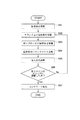
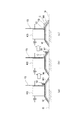
本実施形態によるマウンド被覆工法について図1〜図4を参照して説明する。図1は本実施形態によるマウンド被覆工法の各工程S01〜S07を説明するためのフローチャートである。図2は図1のマウンド被覆工法に使用可能な袋状体の概略的な平面図である。図3は図2の袋状体を巻回した状態を概略的に示す側面図(a)および図2の袋状体を折り畳んだ状態を概略的に示す側面図である。図4は図1のマウンド被覆工法の各工程を説明するためにケーソンおよびマウンド等を概略的に示す側断面図(a)〜(c)である。 The mound coating method according to the present embodiment will be described with reference to FIGS. FIG. 1 is a flowchart for explaining the steps S01 to S07 of the mound covering method according to the present embodiment. FIG. 2 is a schematic plan view of a bag-like body that can be used in the mound covering method of FIG. 3 is a side view schematically showing a state in which the bag-like body of FIG. 2 is wound and a side view schematically showing a state in which the bag-like body of FIG. 2 is folded. FIG. 4 is a side sectional view (a) to (c) schematically showing caisson, mound and the like in order to explain each step of the mound covering method of FIG.
図1に示すように、まず、内部にコンクリートやモルタル等が充填可能でかつ可撓性のある袋状体を用意する(S01)。 As shown in FIG. 1, first, a flexible bag-like body that can be filled with concrete, mortar, or the like is prepared (S01).
図2に袋状体の一例として展開した平面を示すが、袋状体10は、全体が展開して拡げられたとき、設置されるマウンドの上端から下端までの距離に対応した長さLを有し、均等に配置された多数の孔11が形成されている。孔11はコンクリート等の充填後、通水部として作用する。
FIG. 2 shows a developed plane as an example of a bag-like body. When the whole of the bag-
また、袋状体10は、ポリエステル繊維や塩化ビニール等の可撓性のある材料から構成され、内部にコンクリートやモルタルが充填可能である。袋状体10の一端側には、コンクリート等の充填のための注入口12が設けられ、他端側の近傍には、コンクリート等の充填時のエア抜きのために小孔10aが複数設けられている。
The bag-
可撓性のある袋状体10は、水底に設置される前、図2の長手方向に巻かれて、図3(a)のように巻回された状態にされ、または、図2の長手方向に折り畳まれて、図3(b)のように折り畳まれた状態にされることが可能である。
The flexible bag-
図4(a)のように、防波堤の構築のために、水底Gに捨石によるマウンドMが形成され、マウンドMの上にケーソンKSが設置されている。この状態で、次に、図4(a)のように、図3(a)の巻回された袋状体10をマウンドMの法面M1の上端近傍に設置する(S02)。袋状体10の一端側の注入口12には、フレキシブルホース15が連結されている。なお、袋状体10は、図3(b)のように折り畳んだ状態としてもよい。
As shown in FIG. 4 (a), for the construction of the breakwater, a mound M made of rubble is formed on the bottom G, and a caisson KS is installed on the mound M. In this state, next, as shown in FIG. 4A, the wound bag-
次に、ポンプ(図示省略)のホースをフレキシブルホース15に連結することで袋状体10と接続する(S03)。なお、ポンプからのホースを予めフレキシブルホース15として袋状体10の注入口12に連結しておいてもよい。また、ポンプは、陸上またはケーソン上に設置してよいが、作業台船に搭載して用いてもよい。
Next, a hose of a pump (not shown) is connected to the bag-
次に、ポンプからコンクリートを圧送し、袋状体10の内部にコンクリートを圧入すると、その圧入により巻回された袋状体10が、図4(b)のように、コンクリートCの充填とともに、注入口12のある一端側から、法面M1の上端から下端へと延びるようにして拡がる。そして、最終的には、図4(c)のように、袋状体10の他端側までコンクリートCが達して袋状体10の内部全体に充填される(S04)。
Next, when concrete is pumped from the pump and concrete is press-fitted into the bag-
次に、潜水士が袋状体10の注入口12からフレキシブルホース15を取り外し、注入口12をひもやバンド等で結束する(S05)。
Next, the diver removes the
図4のケーソンKSは、防波堤の構築のために、紙面垂直方向に複数設置されるので、その各ケーソンのマウンドに対して上記工程S02〜S05を繰り返す(S06)。この場合、袋状体10の設置工程(S02)において、図2の破線に示すように、袋状体10が拡がったとき、隣の袋状体と一部重なるように配置する。
Since a plurality of the caisson KSs in FIG. 4 are installed in the direction perpendicular to the paper surface for the construction of the breakwater, the above steps S02 to S05 are repeated for each caisson mound (S06). In this case, in the installation process (S02) of the bag-
袋状体10の内部に充填されたコンクリートCが硬化することで、袋詰めコンクリート被覆工が完成する(S07)。このようにして、マウンドMをコンクリートが充填された袋状体10で被覆する。
The concrete C filled in the bag-
上述のように、本実施形態のマウンド被覆工法によれば、袋状体10にコンクリートが流し込まれることで、袋状体10はマウンドMの法面M1に拡がるが、このとき、法面M1に不陸があっても、袋状体10は可撓性があり流し込まれるコンクリートは硬化前で柔らかいので、不陸の凹凸形状に追従することができる。このため、袋詰めコンクリート被覆工を、マウンドMの法面M1の不陸に応じた形状で構築することができる。したがって、被覆前におけるマウンドMの水中ならし作業が不要となり、工期短縮、施工コスト削減および安全性向上に寄与することができる。
As described above, according to the mound covering method of the present embodiment, the concrete is poured into the bag-
また、巻回した(または折り畳んだ)袋状体10をマウンドMに設置し、この袋状体10にポンプでコンクリートを圧入するだけでよいので、マウンド水深が深い場合でも施工が容易となる。
In addition, since the wound (or folded) bag-
また、津波等により防波堤等のマウンドが被害を受けたとき、十分な石材や被覆ブロックの確保が困難な場合であっても早期復旧の実現を図ることができる。 In addition, when a mound such as a breakwater is damaged by a tsunami or the like, early restoration can be achieved even when it is difficult to secure sufficient stones and covering blocks.
また、完成した袋詰めコンクリート被覆工は、たとえば厚さ数10cm程度で、大面積を覆う大重量の被覆工となるとともに、図2のように多数の孔11が形成されて通水部として機能するので、波浪や水流により大きな揚圧力や流体力が発生しても、それらに対して安定性を維持することができる。
Further, the completed bagged concrete covering work is, for example, about a few tens of centimeters thick and is a heavy covering work covering a large area, and a large number of
また、工程S04で袋状体10の内部に圧入するコンクリートは、スランプフロー50cm以上のフレッシュ性状を有することが好ましい。これにより、コンクリートが良好な流動性および充填性を持つことができ、袋状体10の内部へ確実に流動し充填され、その充填時の圧力により袋状体10を確実に展開し拡げることができる。
Moreover, it is preferable that the concrete press-fitted into the bag-shaped
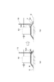
次に、図4のマウンド被覆工法の別の例について図5を参照して説明する。図5は、図4のマウンド被覆工法の別の例の各工程を説明するためにケーソンおよびマウンド等を概略的に示す側断面図(a)(b)である。 Next, another example of the mound covering method shown in FIG. 4 will be described with reference to FIG. FIGS. 5A and 5B are side cross-sectional views (a) and (b) schematically showing caisson, mound and the like in order to explain each process of another example of the mound covering method shown in FIG.
本例では、図2の袋状体のほぼ中央にコンクリートの注入口を配置し、図5(a)のように、袋状体10Aを、注入口を中心にして別々に巻く。このように二箇所で巻回状態にされた袋状体10Aを、図5(a)のようにマウンドMの法面M1のほぼ中央に設置する。なお、袋状体10Aは図3(b)のように折り畳んだ状態としてもよい。また、エア抜きのために小孔は袋状体10Aの両端側に設ける。
In this example, a concrete injection port is arranged at substantially the center of the bag-like body of FIG. 2, and the bag-
次に、図1の工程S03,S04と同様にして、袋状体10Aにコンクリートを圧入することで、図4(b)のように、袋状体10Aを法面M1の上端、下端へと拡げながら袋状体10Aにコンクリートを充填する。
Next, in the same manner as in steps S03 and S04 of FIG. 1, by pressing concrete into the bag-
次に、図1の工程S05〜S07と同様にして、袋詰めコンクリート被覆工が完成する。 Next, in the same manner as steps S05 to S07 in FIG.
図5の例によれば、コンクリートが流し込まれて袋状体10A内で流動する距離が、図2,図4の場合と比べてほぼ半分の長さとなるので、コンクリートの充填をより確実に行うことができる。
According to the example of FIG. 5, the distance that the concrete is poured and flows in the bag-
次に、図2の袋状体の別の二例について図6,図7を参照して説明する。図6,図7の各袋状体は、隣の袋状体と組み合わせることで通水部が形成されるようにしたものである。 Next, another two examples of the bag-like body of FIG. 2 will be described with reference to FIGS. Each of the bag-like bodies in FIGS. 6 and 7 is formed by combining with an adjacent bag-like body to form a water passage.
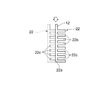
図6は、図1のマウンド被覆工法に使用可能な別の袋状体の概略的な平面図である。図7は、図1のマウンド被覆工法に使用可能なさらに別の袋状体の概略的な平面図である。 FIG. 6 is a schematic plan view of another bag-like body that can be used in the mound covering method of FIG. 1. FIG. 7 is a schematic plan view of still another bag-like body that can be used in the mound covering method of FIG.
図6の袋状体21は、内部にコンクリートやモルタル等が充填可能でかつ可撓性を有する。袋状体21は、コンクリートの注入口12から長手方向に細長く延びる中央部21aと、中央部21aから短手方向両側に枝分かれするようにして延びる複数の枝状部21bと、を有し、枝型に構成されている。袋状体21は、図2と同様の材料から可撓性に構成され、図3(a)の巻回状態または図3(b)の折り畳み状態とされて図4(a)または図5(a)のようにマウンドMに設置される。
The bag-
コンクリートの充填された袋状体21が図6のように拡がって設置されてから、隣の袋状体21を、破線で示すように、枝状部21bと21bとの間にできた空間21cにその隣の袋状体21の枝状部21bが位置するように配置する。この配置のとき、図6の実線で示す袋状体21の枝状部21bと、破線で示す隣の袋状体21の枝状部21bとの間に隙間21dが形成されるようにする。このようにして形成された多数の隙間21dが通水部として機能する。
After the bag-
図7の袋状体22は、内部にコンクリートやモルタル等が充填可能でかつ可撓性を有する。袋状体22は、コンクリートの注入口12から長手方向に細長く延びる中央部22aと、中央部22aから短手方向片側に枝分かれするようにして延びる複数の枝状部22bと、を有し、片枝型に構成されている。袋状体22は、図2と同様の材料から可撓性に構成され、図3(a)の巻回状態または図3(b)の折り畳み状態とされて図4(a)または図5(a)のようにマウンドMに設置される。
The bag-
コンクリートの充填された袋状体22が図7のように拡がって設置されてから、隣の袋状体22を、破線で示すように、枝状部22bが中央部22aの側面に接する(または一部重なる)ように配置する。これにより、図7の破線で示す隣の袋状体22の枝状部22bと枝状部22cとの間の多数の空間22cが通水部として機能する。
After the bag-
以上のように本発明を実施するための形態について説明したが、本発明はこれらに限定されるものではなく、本発明の技術的思想の範囲内で各種の変形が可能である。例えば、本実施形態では、袋状体にコンクリート(またはモルタル)を充填するようにしたが、本発明は、これに限定されず、たとえば、処理土にセメント等の固化材を混合させた固化体であってもよい。 As described above, the modes for carrying out the present invention have been described. However, the present invention is not limited to these, and various modifications can be made within the scope of the technical idea of the present invention. For example, in the present embodiment, the bag-like body is filled with concrete (or mortar), but the present invention is not limited to this. For example, the solidified body obtained by mixing a solidified material such as cement with the treated soil. It may be.
また、図2の多数の孔11による通水部の開口面積は、図2のように完全に拡がった袋状体10の面積に対し、10%程度が好ましい。また、孔11の形状は、図2では正方形状としたが、これに限定されず、円形や長方形等の形状としてもよい。
2 is preferably about 10% of the area of the bag-
10,10A 袋状体
11 孔
12 注入口
15 フレキシブルホース
21,22 袋状体
G 水底
M マウンド
M1 法面
10, 10A bag-
Claims (4)
前記袋状体を巻回した状態または折り畳んだ状態で被覆対象のマウンド面の一部に設置する工程と、
前記袋状体の内部に連通するホースを通して流動性のあるコンクリートまたは固化体を前記袋状体に圧入することで前記袋状体を拡げながら前記袋状体に充填する工程と、を含み、
前記マウンド面を前記コンクリートまたは固化体が充填された袋状体で被覆することを特徴とするマウンド被覆工法。 Preparing a flexible bag-like body that can be filled with concrete or solidified body;
Installing the bag-like body on a part of the mound surface to be covered in a wound or folded state; and
Filling the bag-like body while expanding the bag-like body by press-fitting fluid concrete or solidified body into the bag-like body through a hose communicating with the inside of the bag-like body, and
A mound covering method characterized by covering the mound surface with a bag-like body filled with the concrete or solidified body.
Priority Applications (1)
| Application Number | Priority Date | Filing Date | Title |
|---|---|---|---|
| JP2012015470A JP5946646B2 (en) | 2012-01-27 | 2012-01-27 | Mound covering method |
Applications Claiming Priority (1)
| Application Number | Priority Date | Filing Date | Title |
|---|---|---|---|
| JP2012015470A JP5946646B2 (en) | 2012-01-27 | 2012-01-27 | Mound covering method |
Publications (2)
| Publication Number | Publication Date |
|---|---|
| JP2013155502A true JP2013155502A (en) | 2013-08-15 |
| JP5946646B2 JP5946646B2 (en) | 2016-07-06 |
Family
ID=49050973
Family Applications (1)
| Application Number | Title | Priority Date | Filing Date |
|---|---|---|---|
| JP2012015470A Active JP5946646B2 (en) | 2012-01-27 | 2012-01-27 | Mound covering method |
Country Status (1)
| Country | Link |
|---|---|
| JP (1) | JP5946646B2 (en) |
Citations (7)
| Publication number | Priority date | Publication date | Assignee | Title |
|---|---|---|---|---|
| JPS5891224A (en) * | 1981-11-20 | 1983-05-31 | Penta Ocean Constr Co Ltd | Foot protection work for rubble-mound foundation of underwater structure and bag therefore |
| JPS59228510A (en) * | 1983-06-10 | 1984-12-21 | Yamamizu Sangyo Kk | Laying method of slope covering sheet |
| JPH0258033U (en) * | 1988-10-24 | 1990-04-26 | ||
| JP2000319847A (en) * | 1999-05-14 | 2000-11-21 | Toyo Constr Co Ltd | Covering method for face of slope of rubble mound |
| JP2005290836A (en) * | 2004-03-31 | 2005-10-20 | Tokyo Electric Power Co Inc:The | Concrete placement method |
| JP2007031215A (en) * | 2005-07-27 | 2007-02-08 | Ube Ind Ltd | Fine powder for concrete composition and fresh concrete |
| JP2009179494A (en) * | 2008-01-29 | 2009-08-13 | Taiheiyo Cement Corp | Heavy concrete |
-
2012
- 2012-01-27 JP JP2012015470A patent/JP5946646B2/en active Active
Patent Citations (7)
| Publication number | Priority date | Publication date | Assignee | Title |
|---|---|---|---|---|
| JPS5891224A (en) * | 1981-11-20 | 1983-05-31 | Penta Ocean Constr Co Ltd | Foot protection work for rubble-mound foundation of underwater structure and bag therefore |
| JPS59228510A (en) * | 1983-06-10 | 1984-12-21 | Yamamizu Sangyo Kk | Laying method of slope covering sheet |
| JPH0258033U (en) * | 1988-10-24 | 1990-04-26 | ||
| JP2000319847A (en) * | 1999-05-14 | 2000-11-21 | Toyo Constr Co Ltd | Covering method for face of slope of rubble mound |
| JP2005290836A (en) * | 2004-03-31 | 2005-10-20 | Tokyo Electric Power Co Inc:The | Concrete placement method |
| JP2007031215A (en) * | 2005-07-27 | 2007-02-08 | Ube Ind Ltd | Fine powder for concrete composition and fresh concrete |
| JP2009179494A (en) * | 2008-01-29 | 2009-08-13 | Taiheiyo Cement Corp | Heavy concrete |
Also Published As
| Publication number | Publication date |
|---|---|
| JP5946646B2 (en) | 2016-07-06 |
Similar Documents
| Publication | Publication Date | Title |
|---|---|---|
| KR102022341B1 (en) | Construruction method for underwater concrete block structure | |
| CN103233444B (en) | Underwater dumped rockfill bedding and side slope Anti-scouring structure and construction method thereof | |
| CN105256811B (en) | Construction method for foundation pit supporting and protecting through sheet pile supporting structure with water stopping function | |
| JP5946646B2 (en) | Mound covering method | |
| CN103911978A (en) | Offshore prefabricated platform and mounting method thereof | |
| KR940002457B1 (en) | Method and device for strengthening bearing capacity of soft ground and forming barrier wall | |
| CN106592613B (en) | A kind of Bridge Pier Construction cofferdam structure | |
| KR101104957B1 (en) | block | |
| AU2016200205B2 (en) | Concrete Block Mat Installation by Gravity Flow | |
| JP2015161065A (en) | Liquefaction prevention structure for housing ground | |
| TWI558887B (en) | Construction methods and filling methods for weak sites and sites with liquefaction concerns, as well as structural bags | |
| JP2004162426A (en) | Foundation cell, cell foundation structure and construction method of cell foundation structure | |
| CN208965494U (en) | Dome square light caisson and pile foundation combined breakwater | |
| RU120972U1 (en) | BASE OF HYDROTECHNICAL STRUCTURE | |
| KR102762119B1 (en) | A method for installing a marine breakwater wall using a cylindrical device of the TSP method | |
| JP7183218B2 (en) | Steel impermeable wall, water impermeable method of steel impermeable wall | |
| KR101404471B1 (en) | Embankment constuction by buoyancy and water pressure on the part prevention of injury and in the force functioning bottom, a mat and execution method for filter | |
| JP2022045748A (en) | Concrete structure construction method and concrete structure | |
| CN203878554U (en) | Prefabricated offshore platform | |
| CN105780725B (en) | Method for building dike on water | |
| RU170657U1 (en) | REVETMENT | |
| CN120384775B (en) | A flexible, layer-by-layer construction method for paste-based filling retaining walls | |
| KR100487140B1 (en) | Y-shaped structure element, construction methods of deep foundations and retaining structures by using the Y-shaped structure element | |
| CN108442324A (en) | Works water outlet temporary blocking device and method for blocking | |
| RU2625675C1 (en) | Revetment |
Legal Events
| Date | Code | Title | Description |
|---|---|---|---|
| A621 | Written request for application examination |
Free format text: JAPANESE INTERMEDIATE CODE: A621 Effective date: 20141201 |
|
| A977 | Report on retrieval |
Free format text: JAPANESE INTERMEDIATE CODE: A971007 Effective date: 20150827 |
|
| A131 | Notification of reasons for refusal |
Free format text: JAPANESE INTERMEDIATE CODE: A131 Effective date: 20150902 |
|
| A521 | Request for written amendment filed |
Free format text: JAPANESE INTERMEDIATE CODE: A523 Effective date: 20151014 |
|
| A02 | Decision of refusal |
Free format text: JAPANESE INTERMEDIATE CODE: A02 Effective date: 20160314 |
|
| A521 | Request for written amendment filed |
Free format text: JAPANESE INTERMEDIATE CODE: A523 Effective date: 20160427 |
|
| A911 | Transfer to examiner for re-examination before appeal (zenchi) |
Free format text: JAPANESE INTERMEDIATE CODE: A911 Effective date: 20160516 |
|
| TRDD | Decision of grant or rejection written | ||
| A01 | Written decision to grant a patent or to grant a registration (utility model) |
Free format text: JAPANESE INTERMEDIATE CODE: A01 Effective date: 20160530 |
|
| A61 | First payment of annual fees (during grant procedure) |
Free format text: JAPANESE INTERMEDIATE CODE: A61 Effective date: 20160601 |
|
| R150 | Certificate of patent or registration of utility model |
Ref document number: 5946646 Country of ref document: JP Free format text: JAPANESE INTERMEDIATE CODE: R150 |
|
| R250 | Receipt of annual fees |
Free format text: JAPANESE INTERMEDIATE CODE: R250 |
|
| R250 | Receipt of annual fees |
Free format text: JAPANESE INTERMEDIATE CODE: R250 |
|
| R250 | Receipt of annual fees |
Free format text: JAPANESE INTERMEDIATE CODE: R250 |
|
| R250 | Receipt of annual fees |
Free format text: JAPANESE INTERMEDIATE CODE: R250 |