JP2013176830A - Machine Tools - Google Patents
Machine Tools Download PDFInfo
- Publication number
- JP2013176830A JP2013176830A JP2012123520A JP2012123520A JP2013176830A JP 2013176830 A JP2013176830 A JP 2013176830A JP 2012123520 A JP2012123520 A JP 2012123520A JP 2012123520 A JP2012123520 A JP 2012123520A JP 2013176830 A JP2013176830 A JP 2013176830A
- Authority
- JP
- Japan
- Prior art keywords
- cam
- positioning
- arm
- gripping arm
- tool
- Prior art date
- Legal status (The legal status is an assumption and is not a legal conclusion. Google has not performed a legal analysis and makes no representation as to the accuracy of the status listed.)
- Granted
Links
- 238000003754 machining Methods 0.000 claims abstract description 22
- 238000012545 processing Methods 0.000 claims description 44
- 238000000926 separation method Methods 0.000 claims description 26
- 238000013459 approach Methods 0.000 claims description 25
- 230000032258 transport Effects 0.000 claims description 5
- 230000007246 mechanism Effects 0.000 abstract description 50
- 230000008859 change Effects 0.000 abstract description 3
- 230000004048 modification Effects 0.000 description 11
- 238000012986 modification Methods 0.000 description 11
- 238000003780 insertion Methods 0.000 description 8
- 230000037431 insertion Effects 0.000 description 8
- 230000002093 peripheral effect Effects 0.000 description 6
- 238000000034 method Methods 0.000 description 5
- 230000008569 process Effects 0.000 description 5
- 239000000758 substrate Substances 0.000 description 4
- 238000003860 storage Methods 0.000 description 3
- 230000006835 compression Effects 0.000 description 2
- 238000007906 compression Methods 0.000 description 2
- 238000006073 displacement reaction Methods 0.000 description 2
- 230000000149 penetrating effect Effects 0.000 description 2
- 238000003825 pressing Methods 0.000 description 2
- 238000005520 cutting process Methods 0.000 description 1
- 239000000314 lubricant Substances 0.000 description 1
- 238000003801 milling Methods 0.000 description 1
- 238000010079 rubber tapping Methods 0.000 description 1
- 239000007787 solid Substances 0.000 description 1
- 125000006850 spacer group Chemical group 0.000 description 1
Images


Classifications
-
- B—PERFORMING OPERATIONS; TRANSPORTING
- B23—MACHINE TOOLS; METAL-WORKING NOT OTHERWISE PROVIDED FOR
- B23Q—DETAILS, COMPONENTS, OR ACCESSORIES FOR MACHINE TOOLS, e.g. ARRANGEMENTS FOR COPYING OR CONTROLLING; MACHINE TOOLS IN GENERAL CHARACTERISED BY THE CONSTRUCTION OF PARTICULAR DETAILS OR COMPONENTS; COMBINATIONS OR ASSOCIATIONS OF METAL-WORKING MACHINES, NOT DIRECTED TO A PARTICULAR RESULT
- B23Q3/00—Devices holding, supporting, or positioning work or tools, of a kind normally removable from the machine
- B23Q3/155—Arrangements for automatic insertion or removal of tools, e.g. combined with manual handling
- B23Q3/1552—Arrangements for automatic insertion or removal of tools, e.g. combined with manual handling parts of devices for automatically inserting or removing tools
- B23Q3/1554—Transfer mechanisms, e.g. tool gripping arms; Drive mechanisms therefore
- B23Q2003/155414—Transfer mechanisms, e.g. tool gripping arms; Drive mechanisms therefore the transfer mechanism comprising two or more grippers
- B23Q2003/155425—Transfer mechanisms, e.g. tool gripping arms; Drive mechanisms therefore the transfer mechanism comprising two or more grippers pivotable
- B23Q2003/155428—Transfer mechanisms, e.g. tool gripping arms; Drive mechanisms therefore the transfer mechanism comprising two or more grippers pivotable about a common axis
Landscapes
- Engineering & Computer Science (AREA)
- Mechanical Engineering (AREA)
- Automatic Tool Replacement In Machine Tools (AREA)
Abstract
【課題】駆動源から離反した交換位置において、工具と加工部との位置を整合させることができる工作機械を提供する。
【解決手段】位置決めカムフォロワ83及び位置決め片86を有する位置決め機構を設ける。工具交換持において主軸ヘッド32が加工位置及び交換位置の間を移動する場合、主軸ヘッド32に設けた位置決めカム63に位置決めカムフォロワ83を当接させる。位置決めカム63から位置決めカムフォロワ83に力が作用し、位置決め片86は把持アーム70のアーム枢軸77に向けて移動する。位置決め片86は把持アーム70に対しアーム枢軸77の軸方向における位置決めを行う。その後工具ホルダ11(工具)の交換を行い、主軸34に工具を確実に装着する。
【選択図】図20A machine tool capable of aligning the positions of a tool and a machining part at an exchange position separated from a drive source.
A positioning mechanism having a positioning cam follower 83 and a positioning piece 86 is provided. When the spindle head 32 moves between the machining position and the exchange position during tool change, the positioning cam follower 83 is brought into contact with the positioning cam 63 provided on the spindle head 32. A force acts on the positioning cam follower 83 from the positioning cam 63, and the positioning piece 86 moves toward the arm pivot 77 of the gripping arm 70. The positioning piece 86 positions the gripping arm 70 in the axial direction of the arm pivot 77. Thereafter, the tool holder 11 (tool) is replaced, and the tool is securely mounted on the spindle 34.
[Selection] Figure 20
Description
本発明は、工具を把持する把持アームを、工具を交換する交換位置に搬送し、搬送した把持アームに把持された工具を加工位置から交換位置に移動した加工部に装着し、加工部を加工位置に移動させてワークを加工する工作機械に関する。 The present invention transports a gripping arm that grips a tool to an exchange position for exchanging the tool, attaches the tool gripped by the transported gripping arm to a processing unit that has moved from the processing position to the replacement position, and processes the processing unit. The present invention relates to a machine tool for machining a workpiece by moving it to a position.
一般に工作機械は、フライス加工、ねじ立て等種々の加工を行う。工作機械は、複数の工具を格納する工具マガジンを備える。工具マガジンは複数の工具を循環させることができる。工作機械は制御部からの指令に基づき工具マガジンにて工具を循環させて、所定の工具を取り出す。そして加工部(例えば主軸)に装着された工具と交換し、目的の加工を行う。 In general, machine tools perform various processes such as milling and tapping. The machine tool includes a tool magazine that stores a plurality of tools. The tool magazine can circulate a plurality of tools. The machine tool circulates the tool in the tool magazine based on a command from the control unit and takes out a predetermined tool. Then, the tool is exchanged with a tool mounted on the processing portion (for example, the main shaft), and the target processing is performed.
特許文献1には、工具収納装置(工具マガジン)及び該工具収納装置を備える工作機械が開示してある。工具収納装置は、チェーン及びスプロケットを有し、チェーンには工具を収容する複数の工具ポットが連結している。スプロケットはモータ等の駆動源に連結しており、スプロケットの回転によって所望の工具ポット(工具)を、工具を交換する交換位置に搬送する。 Patent Document 1 discloses a tool storage device (tool magazine) and a machine tool including the tool storage device. The tool storage device has a chain and a sprocket, and a plurality of tool pots for storing tools are connected to the chain. The sprocket is connected to a drive source such as a motor, and a desired tool pot (tool) is conveyed to an exchange position where the tool is exchanged by the rotation of the sprocket.
チェーンは複数の部品を連結して構成し、スプロケットに噛合した位置から離れるに従って各部品の寸法公差が累積する。そのため工具を交換位置まで搬送するために必要な予め算出した回転数だけスプロケットを回転させても、交換位置から偏倚した位置に工具が搬送することがある。 The chain is formed by connecting a plurality of parts, and the dimensional tolerance of each part accumulates as the distance from the position meshed with the sprocket increases. Therefore, even if the sprocket is rotated by the number of rotations calculated in advance necessary for transporting the tool to the replacement position, the tool may be transported to a position deviated from the replacement position.
その場合、工具と加工部との位置が整合せず、工具の加工部への取り付けが不可能になるか又は本来の位置から偏倚した位置に工具を取り付けた状態で加工部が回転し、ワークの加工中に工具が破損するおそれがある。 In that case, the position of the tool and the processing part does not match, and it becomes impossible to attach the tool to the processing part, or the processing part rotates with the tool attached to a position deviated from the original position. There is a risk of damage to the tool during machining.
本発明は斯かる事情に鑑みてなされたものであり、駆動源から離反した交換位置において、工具と加工部との位置を整合させることができる工作機械を提供することを目的とする。 The present invention has been made in view of such circumstances, and an object of the present invention is to provide a machine tool capable of aligning the positions of a tool and a machining portion at an exchange position separated from a drive source.
本発明に係る工作機械は、工具を把持し、中途部に設けた枢軸によって回転可能な複数の把持アームと、該把持アームを工具を交換する交換位置に搬送する搬送部と、前記把持アームに把持された工具を装着してワークを加工する加工部とを備え、該加工部はワークを加工する加工位置と交換位置との間を移動するようにしてある工作機械であって、前記加工部の移動によって前記加工部と同方向に移動するカムと、該カムに当接するカムフォロワを有し、前記枢軸の軸方向における前記把持アームの位置決めを行う位置決め部とを備えることを特徴とする。 A machine tool according to the present invention includes a plurality of gripping arms that grip a tool and can be rotated by a pivot provided in the middle, a transport unit that transports the gripping arm to an exchange position for exchanging the tool, and the gripping arm. A machine tool for machining a workpiece by attaching a gripped tool, the machine tool being configured to move between a machining position for machining a workpiece and an exchange position, And a cam that moves in the same direction as the processing portion, and a positioning portion that has a cam follower that contacts the cam and positions the gripping arm in the axial direction of the pivot.
本発明においては、カムフォロワを有する位置決め部を設けており、工具交換時において加工部が加工位置及び交換位置の間を移動する場合に、加工部に設けたカムにカムフォロワを当接させる。カムからカムフォロワに力が作用し、位置決め部は把持アームの枢軸に向けて移動する。位置決め部は把持アームを枢軸の軸方向にて位置決めし、工具交換が行われる。把持アームは、枢軸の軸方向が工具マガジンの循環方向に沿うように配設してあり、交換位置における循環方向の位置ずれは、枢軸の軸方向の位置ずれとなって表れる。そのため軸方向の位置決めは循環方向の位置決めとなる。 In this invention, the positioning part which has a cam follower is provided, and when a process part moves between a process position and an exchange position at the time of tool exchange, a cam follower is made to contact | abut to the cam provided in the process part. A force acts on the cam follower from the cam, and the positioning portion moves toward the pivot axis of the gripping arm. The positioning unit positions the gripping arm in the axial direction of the pivot and performs tool change. The gripping arm is disposed so that the axial direction of the pivot is along the circulation direction of the tool magazine, and the displacement in the circulation direction at the replacement position appears as a displacement in the axial direction of the pivot. Therefore, the positioning in the axial direction is the positioning in the circulation direction.
本発明に係る工作機械は、前記位置決め部が、中途部に設けた回転軸を支点にして回転する回転杆を有し、前記回転杆の一端部に前記カムフォロワを設けてあり、前記把持アームは、前記回転杵の回転によって前記回転杆の他端部が嵌合する嵌合部を有することを特徴とする。 In the machine tool according to the present invention, the positioning portion has a rotating rod that rotates about a rotation shaft provided in the middle portion, the cam follower is provided at one end of the rotating rod, and the gripping arm is The rotating rod has a fitting portion with which the other end of the rotating rod is fitted.
本発明においては、カムからカムフォロワに力が作用した場合、回転杆は回転軸を支点にして回転する。回転杆の他端部は把持アームが有する嵌合部に嵌合し、把持アームを枢軸の軸方向に位置決めする。 In the present invention, when force is applied from the cam to the cam follower, the rotary rod rotates about the rotation shaft. The other end of the rotary rod is fitted into a fitting portion of the gripping arm, and the gripping arm is positioned in the axial direction of the pivot.
本発明に係る工作機械は、前記嵌合部が、前記枢軸に外挿された環状をなし、外周に溝(又は突起)が周設してあり、前記回転杆は、前記溝(又は突起)に嵌合する突起(又は溝)を前記他端部に有することを特徴とする。 In the machine tool according to the present invention, the fitting portion has an annular shape that is extrapolated to the pivot, and a groove (or protrusion) is provided on the outer periphery, and the rotary rod is the groove (or protrusion). The other end portion has a protrusion (or a groove) that fits into the other end portion.
本発明においては、環状の嵌合部が枢軸に外挿されており、嵌合部の外周に溝(又は突起)が周設してある。回転杆は他端部に突起(又は溝)を有し、嵌合部に嵌合する。 In this invention, the annular fitting part is extrapolated by the pivot, and the groove | channel (or protrusion) is provided in the outer periphery of the fitting part. The rotary rod has a protrusion (or groove) at the other end and is fitted into the fitting portion.
本発明に係る工作機械は、前記カムフォロワが前記カムに接触する位置と前記支点との間の寸法が、前記他端部が前記嵌合部に接触する位置と前記支点との間の寸法よりも大きいことを特徴とする。 In the machine tool according to the present invention, the dimension between the position where the cam follower contacts the cam and the fulcrum is larger than the dimension between the position where the other end contacts the fitting part and the fulcrum. It is large.
本発明においては、カムフォロワがカムに接触する位置と回転杆の回転中心となる支点との間の寸法が、回転杆の他端部が前記嵌合部に接触する位置と前記支点との間の寸法よりも大きくなるようにしてある。これにより、カムから回転杆に作用する力に基づいて他端部から嵌合部へ作用させる力を大きくすることができる。 In the present invention, the dimension between the position where the cam follower comes into contact with the cam and the fulcrum serving as the rotation center of the rotary rod is between the position where the other end of the rotary rod contacts the fitting portion and the fulcrum. It is designed to be larger than the dimensions. Thereby, based on the force which acts on a rotary rod from a cam, the force made to act on a fitting part from an other end part can be enlarged.
本発明に係る工作機械は、前記カムをカム面に交差する方向へ付勢する付勢手段を備えることを特徴とする。 The machine tool according to the present invention is characterized by comprising a biasing means for biasing the cam in a direction intersecting the cam surface.
本発明においては、カムは付勢手段によりカム面に交差する方向へ付勢されている。カムまたはカムフォロアに工作時の切粉などの異物が付着した場合でも、付勢力以上の力が働けばカムが浮動することによって、カム及びカムフォロワ間に異物が噛み込まれて停止することを防ぐ。 In the present invention, the cam is biased in a direction intersecting the cam surface by the biasing means. Even when foreign matter such as cutting chips adheres to the cam or cam follower, if the force exceeding the urging force is applied, the cam floats to prevent foreign matter from being caught between the cam and cam follower and stopping.
本発明に係る工作機械は、前記位置決め部は、中途部に設けた回転軸を支点にして回転する回転杆を有し、前記回転杆の一端部に前記カムフォロワを設けてあり、前記回転杆の他端部に前記枢軸の両端部に対向する軸方向位置決め部を設けてあることを特徴とする。 In the machine tool according to the present invention, the positioning unit has a rotating rod that rotates about a rotating shaft provided in a middle portion, the cam follower is provided at one end of the rotating rod, The other end portion is provided with an axial positioning portion facing both end portions of the pivot.
本発明においては、カムからカムフォロワに力が作用した場合、回転杆は回転軸を支点にして回転する。軸方向位置決め部は枢軸の両端部に対向し、軸方向にて枢軸の位置を規制し、把持アームを軸方向に位置決めする。 In the present invention, when force is applied from the cam to the cam follower, the rotary rod rotates about the rotation shaft. The axial positioning portion faces both ends of the pivot, restricts the position of the pivot in the axial direction, and positions the gripping arm in the axial direction.
本発明に係る工作機械は、前記枢軸の両端部にテーパが形成してあり、前記軸方向位置決め部に前記テーパに対応した傾斜面が形成してあることを特徴とする。 The machine tool according to the present invention is characterized in that a taper is formed at both ends of the pivot, and an inclined surface corresponding to the taper is formed at the axial positioning portion.
本発明においては、枢軸にテーパを形成し、該テーパに対応した傾斜面を軸方向位置決め部に形成する。例えばテーパ及び傾斜面の傾斜角を略同じに設計する。回転杆が回転し、軸方向位置決め部が枢軸の両端部に近接した場合、軸方向位置決め部は円滑に枢軸に接触し、把持アームの位置決めが円滑に実現される。 In the present invention, a taper is formed on the pivot, and an inclined surface corresponding to the taper is formed on the axial positioning portion. For example, the inclination angles of the taper and the inclined surface are designed to be substantially the same. When the rotary rod rotates and the axial positioning portion comes close to both ends of the pivot, the axial positioning portion smoothly contacts the pivot and positioning of the gripping arm is realized smoothly.
本発明に係る工作機械は、前記枢軸の軸方向に交差する方向における前記把持アームの位置決めを行う第2位置決め部が前記把持アームに設けてあり、前記第2位置決め部が当接する被当接部を備えることを特徴とする。 In the machine tool according to the present invention, a second positioning portion for positioning the gripping arm in a direction intersecting the axial direction of the pivot is provided in the gripping arm, and the contacted portion with which the second positioning portion abuts It is characterized by providing.
本発明においては、第2位置決め部が被当接部に当接し、枢軸の軸方向に交差する方向において、把持アームの位置決めを行う。例えば枢軸の軸方向が左右方向の場合、第2位置決め部によって前後方向及び上下方向の位置決めを行う。 In the present invention, the second positioning portion contacts the contacted portion, and the grip arm is positioned in a direction intersecting the axial direction of the pivot. For example, when the axial direction of the pivot is the left-right direction, the second positioning portion performs positioning in the front-rear direction and the up-down direction.
本発明に係る工作機械は、前記把持アームは一端部にて工具を把持するようにしてあり、前記第2位置決め部は前記把持アームの他端部から前記枢軸の軸方向に直交する一方向に突出しており、前記枢軸の軸方向に直交する二方向にて前記被当接部に当接するようにしてあることを特徴とする。 In the machine tool according to the present invention, the gripping arm grips a tool at one end, and the second positioning portion extends in a direction perpendicular to the axial direction of the pivot from the other end of the gripping arm. It protrudes and contacts the contacted part in two directions orthogonal to the axial direction of the pivot.
本発明においては、第2位置決め部は前記枢軸の軸方向に直交する一方向に突出し、前記軸方向に直交する二方向にて前記被当接部に当接する。把持アームは前記二方向において位置決めされる。 In the present invention, the second positioning portion protrudes in one direction orthogonal to the axial direction of the pivot and contacts the contacted portion in two directions orthogonal to the axial direction. The gripping arm is positioned in the two directions.
本発明に係る工作機械は、前記加工部の移動によって前記加工部と同方向に移動し、前記把持アームが当接して前記加工部に接近する接近カム及び前記加工部から離反する離反カムとを備え、前記加工部が加工位置から交換位置に移動する場合、前記把持アームの位置決め後に、前記把持アームは前記接近カムへの当接によって前記加工部に装着した工具を把持するようにしてあり、前記加工部が交換位置から加工位置に移動する場合、前記把持アームの位置決め後に、前記把持アームは前記加工部に工具を装着し、前記離反カムへの当接によって工具から離反するようにしてあることを特徴とする。 The machine tool according to the present invention includes an approach cam that moves in the same direction as the processing portion by the movement of the processing portion, contacts the gripping arm and approaches the processing portion, and a separation cam that moves away from the processing portion. And when the processing unit moves from a processing position to an exchange position, after positioning the gripping arm, the gripping arm grips a tool attached to the processing unit by contacting the approaching cam, When the processing unit moves from the replacement position to the processing position, after the gripping arm is positioned, the gripping arm is mounted with a tool on the processing unit, and is separated from the tool by contact with the separation cam. It is characterized by that.
本発明においては、工具を装着した加工筒が加工位置から交換位置に移動する場合、工具を把持していない把持アームを位置決めした後、把持アームは加工筒に接近して工具を把持する。把持アームは工具を加工筒から取り外す。工具マガジンが回転し、工具を把持した他の把持アームが交換位置に搬送される。加工筒が交換位置から加工位置に移動を開始し、把持アームの位置決めが行われる。把持アームは加工筒に接近して工具を装着する。そして前記把持アームは加工筒から離反する。 In the present invention, when the processing cylinder equipped with the tool moves from the processing position to the replacement position, after the gripping arm not gripping the tool is positioned, the gripping arm approaches the processing cylinder and grips the tool. The gripping arm removes the tool from the processing cylinder. The tool magazine rotates and another gripping arm that grips the tool is transported to the replacement position. The processing cylinder starts to move from the replacement position to the processing position, and the grip arm is positioned. The gripping arm approaches the processing cylinder and mounts the tool. The gripping arm is separated from the processing cylinder.
本発明にあっては、カムフォロワを有する位置決め部を設けており、工具交換時において加工部が加工位置及び交換位置の間を移動する場合に、加工部に設けたカムにカムフォロワを当接させる。カムからカムフォロワに力が作用し、位置決め部は把持アームの枢軸に向けて移動する。位置決め部は把持アームを枢軸の軸方向にて位置決めする。その後、工具の交換が行われる。把持アームの位置決めを終了した後に、工具が交換されるので、工具は加工部に確実に装着され、加工部から脱落することを防止することができる。またワークの加工中に工具又は加工部が破損することを防止することができる。 In the present invention, the positioning part having the cam follower is provided, and when the machining part moves between the machining position and the exchange position when changing the tool, the cam follower is brought into contact with the cam provided in the machining part. A force acts on the cam follower from the cam, and the positioning portion moves toward the pivot axis of the gripping arm. The positioning unit positions the gripping arm in the axial direction of the pivot axis. Thereafter, the tool is changed. Since the tool is replaced after the positioning of the gripping arm is completed, the tool can be securely attached to the processing portion and can be prevented from falling off the processing portion. Further, it is possible to prevent the tool or the processing part from being damaged during the processing of the workpiece.
以下本発明を実施の形態に係る工作機械を示す図面に基づいて詳述する。以下の説明では図において矢印で示す上下、左右及び前後を使用する。作業者は前方で工作機械を操作し、ワークの着脱を行う。図1は工作機械の斜視図であり、図2は工作機械の正面図であり、図3は工作機械の右側面図、図4は工具交換装置及びガイドレールを覆うカバー等を省略した斜視図である。 Hereinafter, the present invention will be described in detail with reference to the drawings showing a machine tool according to an embodiment. In the following description, up and down, left and right, and front and rear indicated by arrows in the figure are used. The operator operates the machine tool in front and attaches / detaches the workpiece. 1 is a perspective view of a machine tool, FIG. 2 is a front view of the machine tool, FIG. 3 is a right side view of the machine tool, and FIG. 4 is a perspective view in which a tool changer and a cover that covers a guide rail are omitted. It is.
工作機械100は、基台20、Y方向移動装置22、X方向移動装置26、コラム28、Z方向移動装置30、主軸ヘッド32(加工部)、工具交換装置10(搬送部)等を備える。基台20は床面上に固定してある。基台20は、Y方向移動装置22、X方向移動装置26を介してコラム28をX方向(左右方向)及びY方向(前後方向)に移動可能に支持する。基台20は、加工対象であるワークを2軸まわりに駆動して保持するワーク保持装置120を支持する。コラム28は、Z方向移動装置30を介して主軸ヘッド32をZ方向(上下方向)に移動可能に支持する。工具交換装置10は、主軸ヘッド32に装着する工具を交換する。
The
Y方向移動装置22は、互いに平行な1対のガイドレール22a,22a、複数のブロック22b,22b,・・・,22b、Y方向移動台22c、及びY方向駆動モータ(図示略)を備える。ガイドレール22a,22aは、左右方向に適当な間隔を空けて基台20の上面に前後方向に延設してある。ブロック22b,22b,・・・,22bはガイドレール22a,22aの夫々に前後方向に移動可能に嵌合している。Y方向移動台22cはブロック22b,22b,・・・,22b上に固定してある。Y方向駆動モータの駆動によって、Y方向移動台22cは前後方向に移動する。
The Y-
X方向移動装置26は、互いに平行な1対のガイドレール26a,26a、複数のブロック26b,26b,・・・,26b、コラム台26c、及びX方向駆動モータ(図示略)を備える。ガイドレール26a,26aは前後方向に適当な間隔を空けて、Y方向移動台22cの上面に左右方向に延設してある。ブロック26b,26b,・・・,26bはガイドレール26a,26aの夫々に左右方向に移動可能に嵌合している。コラム台26cはブロック26b,26b,・・・,26b上に固定してある。X方向駆動モータの駆動によって、コラム28は左右方向に移動する。
コラム28は、コラム台26c上に固定してある。コラム28は、Y方向移動装置22及びX方向移動装置26によってY方向及びX方向に移動する。
The
The
Z方向移動装置30は、互いに平行な1対のガイドレール30a,30a、複数のブロック30b,30b,・・・,30b、主軸ヘッド台30c及びZ方向駆動モータ(図示略)を備える。ガイドレール30a,30aは、左右方向に適当な間隔を空けてコラム28の前面に上下方向に延設してある。複数のブロック30b,30b,・・・,30bはガイドレール30a,30aの夫々に上下方向に移動可能に嵌合している。主軸ヘッド台30cはブロック30b,30b,・・・,30bの前面に固定してある。Z方向駆動モータの駆動によって、主軸ヘッド台30cは上下方向に移動する。
The Z-
主軸ヘッド32は主軸ヘッド台30cに固定してある。X方向駆動モータ、Y方向駆動モータ、及びZ方向駆動モータを駆動制御することで、主軸ヘッド32は前後、左右及び上下に移動する。
The
図5は主軸ヘッド32を略示する部分断面図である。
図5に示すように、主軸ヘッド32は、前方側の内部にZ方向に延びる主軸34を回転可能に保持している。主軸34は、下端部に工具を装着した円筒状の工具ホルダ11を脱着可能に保持する。主軸34は、中空の筒形状をなし、下端部に下方に向かって内径が大きくなるテーパ穴34aが形成してある。工具ホルダ11の上部に形成したテーパ装着部12は、テーパ穴34aに嵌合させて装着する。
FIG. 5 is a partial sectional view schematically showing the
As shown in FIG. 5, the
主軸34には、テーパ穴34aの上方にドローバー(不図示)が主軸34の軸方向に移動可能に挿入してある。ドローバーは、周囲にクランプバネ(不図示)を配設している。ドローバーは、クランプバネの弾性力によって上方に付勢されている。ドローバーの下端部には、コレットチャック(不図示)が設けられている。コレットチャックは、工具ホルダ11のテーパ装着部12を主軸34のテーパ穴34aに装着すると、テーパ装着部12から上方に突出するプルスタッド12aを挟持することができる。コレットチャックは、クランプバネの弾性力によるドローバーの上方への付勢によりプルスタッド12aを挟持した状態で保持する。
In the
ドローバーの上方には、ドローバーを下方に押圧する押圧機構(不図示)が設けられている。押圧機構は、ドローバーをクランプバネの弾性力に抗して下方に押し下げる。ドローバーを下方に押し下げることで、コレットチャックはプルスタッド12aの挟持を解除する。コレットチャックがプルスタッド12aの挟持を解除することで、工具ホルダ11は主軸34から外れる。
A pressing mechanism (not shown) that presses the draw bar downward is provided above the draw bar. The pressing mechanism presses the draw bar downward against the elastic force of the clamp spring. By pushing down the draw bar, the collet chuck releases the
主軸34は、主軸ヘッド32の上端に設けられた主軸モータ35に接続されている。主軸34は、主軸モータ35の駆動により軸心回りに回転する。主軸34は、下端に工具ホルダ11を装着した状態で軸心回りに回転することで、ワーク保持装置120に固定されたワークに対して回転加工を行うことができる。
The
図6はレール部を略示する斜視図、図7はレール部を移動する工具マガジンを略示する斜視図である。
工具交換装置10は、工具マガジン40及びマガジン駆動部50を備える(図6参照)。工具交換装置10は複数の工具ホルダ11を搬送し、主軸34の下端部に工具ホルダ11を着脱する。工具マガジン40は、レール部41及びチェーン部42を備える。レール部41は、支持梁41a,41a、レール台41b、及びレール41cを備える。支持梁41a,41aは、上側を斜辺として前方へ下方傾斜した三角形状をなす板状の構造部材であり、コラム28の左右に片持ちに固定してある。支持梁41a,41aは、コラム28の左右に固定した部分から主軸ヘッド32の両側部分まで前方へ下方傾斜して延設してある。
FIG. 6 is a perspective view schematically illustrating the rail portion, and FIG. 7 is a perspective view schematically illustrating a tool magazine that moves the rail portion.
The
レール台41bは、長円形の環状部材であり、コラム28及び主軸ヘッド32を囲むように支持梁41a,41aに固定して設けてある。レール台41bは、支持梁41a,41aの上側端面に沿って、前面側下方から後面側上方へ延設してあり、水平面から略30度傾斜するように配してある(図3参照)。図6に示すように、レール台41bにおける後方の半円状の部分には、板状の取付台41eが該半円状の周縁から延設してある。取付台41eは、マガジン駆動部50を支持する。
The
図8は移動台を略示する斜視図、図9はレールに取り付けた移動台を略示する断面図である。レール41cは、略矩形状の断面を有し、レール台41b上に長円形で無端状の軌道をなすように形成してある。図9に示すように、レール41cは、長円形の軌道の内周側面及び外周側面に夫々、長円形をなす鍔状の嵌合部41d,41dを有する。該嵌合部41d,41dは、後述する内側ローラ47及び外側ローラ48のV溝に嵌合する。チェーン部42は、複数の移動台43,43,・・・、43、複数のリンク部材44,44,・・・、44、及び複数の把持アーム70,70,・・・、70を備える。複数(例えば11個)の移動台43,43,・・・、43は、夫々レール41cによって支持され、レール41cによる軌道上を移動可能としてある。リンク部材44,44,・・・、44は、隣り合う移動台43,43を連結する。複数の移動台43,43,・・・及びリンク部材44,44,・・・は、無端状のチェーンを形成する。複数(例えば22個)の把持アーム70,70,・・・、70は、夫々移動台43,43,・・・、43の下部に連結してあり、工具ホルダ11を把持する。工具マガジン40は、移動台43,43,・・・、43をレール41cの軌道に沿って循環し、把持アーム70が保持する工具ホルダ11を主軸34下方の交換位置に割り出す。レール台41bが水平面から略30度傾斜して配置してあるため、工具マガジン40の軸心方向は、鉛直線(図3参照)に対して主軸ヘッド32側に略30度傾斜している。
FIG. 8 is a perspective view schematically showing the moving table, and FIG. 9 is a cross-sectional view schematically showing the moving table attached to the rail. The
移動台43は、基板46、内側ローラ47,47、外側ローラ48,48、及び複数のピン49,49,・・・、49を備える。基板46は、略矩形状である。基板46の下面に内側ローラ47,47及び外側ローラ48,48を夫々下面法線方向の軸まわりに回動可能に軸支している。内側ローラ47,47及び外側ローラ48,48は、円板形をなし、外周にV溝を有する。内側ローラ47,47は、レール41cの内周側面に設けた嵌合部41dにV溝により嵌合し、外側ローラ48,48は、レール41cの外周側面に設けた嵌合部41dにV溝により嵌合する。6個のピン49,49,・・・、49が、基板46の上面に立設している。移動台43上の複数(例えば6個)のピン49,49,・・・、49は、レール41cの軌道における半円状の部分に移動台43が位置するときに、該半円と同心の円周上に並ぶように配置してある。複数のピン49,49,・・・、49は後述のギア51に噛合する。
The moving table 43 includes a
リンク部材44,44,・・・、44は、隣り合う移動台43,43を連結している。図に示すように、一つの移動台43に並べた6個のピン49,49,・・・、49の両端から2番目のピン上に連結軸体49b,49bを設けてある。リンク部材44,44,・・・は、連結軸体49b,49bを介して移動台43に連結している。把持アーム70,70,・・・、70は、移動台43,43,・・・43の下部に2台ずつ取り付けてある。後述するように、把持アーム70は工具ホルダ11を把持する下部先端が揺動することにより工具を交換する。把持アーム70,70,・・・、70の詳細については後述する。
The
図7に示すように、マガジン駆動部50は、ギア51及びマガジン駆動モータ52を備え、コラム28の後方に位置する取付台41eに設けてある。ギア51は、例えばトロコイド形状の歯面を有する外歯車であり、取付台41eの上面に回転可能に設けてある。ギア51は取付台41eの上面と略平行である。ギア51は、レール41cの軌道における半円状の部分で、レール41c上を周回する移動台43上のピン49,49,・・・、49に噛合する。ギア51は、ギア径をレール41cの軌道における半円部分の直径より小さく(例えば半分程度と)してある。ギア51は、ギア径を小さくすることにより、工具マガジン40の後方へのオーバーハングを抑え、かつコラム28に機械的に干渉しないようにしている。
As shown in FIG. 7, the
マガジン駆動モータ52は、モータ回転軸がギア51の軸に連結してあり、ギア51を回転駆動する。ギア51は、回転することにより移動台43上のピン49,49,・・・、49をレール41cの円周接線方向に押す。移動台43は、ギア51の回転によりレール41c上を周回する。マガジン駆動モータ52は、ギア51を回転させることにより、移動台43を搬送する。工具を交換する場合、工具マガジン40によって所定の把持アーム70が主軸34の下方の交換位置(レール台41bにおける前方下端部)に搬送される。
The
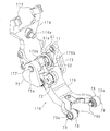
把持アーム70は後述するカム機構60によって揺動し、工具ホルダ11を交換するようにしてある。工具ホルダ11には工具が取り付けてある。図10は、カム機構60、把持アーム70及び位置決め機構を略示する斜視図、図11は、カム機構60を略示する拡大斜視図である。図10及び図11の図面中に矢印で示す前後、左右及び上下は図1に対応している。
The
図10に示すように、主軸ヘッド32の前側面にカム機構60が設けてある。図11に示すように、カム機構60は接近カム61、離反カム62及び位置決めカム63(カム)を備える。接近カム61、離反カム62及び位置決めカム63は、主軸34の前面から突出した上下方向に長い板状をなし、接近カム61、位置決めカム63及び離反カム62の順に左から右に並設されている。接近カム61は、下端よりもやや上側の位置を頂点61aとして上方に向かうに従って突出幅(前後幅)が縮幅する。接近カム61の頂点よりも下側は、下方に向かうに従って突出幅(前後幅)が縮幅する。接近カム61は、上端から下方に向けてテーパ状に高さを増し、頂点61aに連なるカム面61bを有する。
As shown in FIG. 10, a
離反カム62は、上下方向中央部よりも若干上側の部分を平坦な頂部62aとして、下方に向かうに従って突出幅(前後幅)が縮幅する。離反カム62の頂部62aよりも上側は、上方に向かうに従って突出幅が縮幅する。離反カム62は、下端から上方に向けてテーパ状に高さを増し、頂部62aに連なるカム面62bを有する。
接近カム61の上端部は離反カム62よりも上方に位置し、離反カム62の下端部は接近カム61の下端部よりも下方に位置する。離反カム62の頂部62aと接近カム61の頂点61aとは上下方向に離隔しており、両者の前後位置は略同じである。上下方向に対するカム面61bの傾斜角とカム面62bの傾斜角とは略同じであり、互いに逆向きである。
The
The upper end portion of the approaching
位置決めカム63は、上下方向中央部に突出幅が一定の平坦部63aを有する。位置決めカム63の平坦部63aより上側は、上方に向かうに従って突出幅が縮幅する。位置決めカム63の平坦部63aより下側は、下方に向かうに従って突出幅が縮幅する。位置決めカム63の上端部及び下端部は、上端及び下端からテーパ状に高さを増し、平坦部63aに連なる上側カム面63b及び下側カム面63cをそれぞれ有する。上下方向に対する上側カム面63b及び下側カム面63cの傾斜角は、それぞれカム面61bおよびカム面62bの傾斜角と略同じである。
位置決めカム63の上端は、接近カム61の上端よりも上方に位置する。位置決めカム63の下端は、接近カム61の下端と略同じ位置にある。平坦部63aの前後位置は、頂部62aよりも後方に位置し、平坦部63aは頂部62aよりも低い。
接近カム61及び離反カム62は、後述する第1カムフォロワ71及び第2カムフォロワ72に当接し、位置決めカム63は後述する位置決めカムフォロワ83に当接する。
The
The upper end of the
The
図12は、把持アーム70を略示する斜視図である。
図12に示すように、把持アーム70は、前述した移動台43に取り付ける取付板73を備える。取付板73には支持杆74が設けてあり、該支持杆74は取付板73から下方に突出している。支持杆74の中途部に、後述するピン受部81cに当接する位置決めピン74a(第2位置決め部)が設けてある。位置決めピン74aは支持杆74から後方に突出している。
FIG. 12 is a perspective view schematically showing the
As shown in FIG. 12, the
支持杆74の下端部にはブロック74bが設けてある。該ブロック74bの両側面に、後述するアーム部76の回転を案内する案内板75、75がそれぞれ固定してある。案内板75、75は互いに対向している。側面視において、案内板75は、上端部を要として下方に広がる扇状をなす。案内板75の上端部には、後述するアーム枢軸77を挿入するアーム軸孔75aが設けてある。なお前記位置決めピン74aは、アーム軸孔75aの軸方向及び上下方向に対して直交する方向に沿って支持杆74を貫通し、支持杆74から突出している。
A
把持アーム70は両案内板75、75の間に、上下に延び、下側に突出する湾曲した円弧状のアーム部76が設けてある。アーム部76の上端部にはアーム枢軸77(枢軸)が設けてあり、該アーム枢軸77の両端部は、アーム部76の上端部両側から突出している。アーム枢軸77の両端部には周方向に沿ってテーパ77a、77aが形成してある。アーム枢軸77の両端部は、各案内板75、75のアーム軸孔75a、75aに回転可能に挿入してある。アーム部76の下端部は二股に分かれている。二股に分かれた下端部の各先端部に把持ピンユニット79、79を保持する保持円筒78、78が形成してある。保持円筒78は、前記アーム枢軸77と同方向を軸方向としている。なお把持アーム70は、アーム枢軸77がレール41cの軌道接線に沿うように、移動台43に取り付けてある。
The
図8及び図12に示すように、把持ピンユニット79は、有底円筒形のホルダ79aと、該ホルダ79aに収容されたピン79bとを有する。ピン79bの先端部はホルダ79aから突出しており、ホルダ79a内のばね(不図示)によって突出方向に付勢されている。ピン79bの先端面は、外向きに突出した曲面状をなす。両ピン79b、79bの先端面が互いに対向するように、把持ピンユニット79、79はそれぞれ保持円筒78、78に嵌合している。両ピン79b、79bは工具ホルダ11(工具)を脱着するようにしてある。円筒状をなす工具ホルダ11のテーパ装着部12の下側に溝11aが全周に形成してある。両ピン79b、79bの間に工具ホルダ11を挿入した場合、両ピン79b、79bは溝11aに嵌合し、工具ホルダ11を保持する。
As shown in FIGS. 8 and 12, the
アーム枢軸77の上側に前記接近カム61に当接する第1カムフォロワ71が設けてある。第1カムフォロワ71は上方に突出している。第1カムフォロワ71は円形のローラであり、アーム枢軸77と平行な軸回りに回転する。前記アーム部76の中途部に、前記離反カム62に当接する第2カムフォロワ72が設けてある。第2カムフォロワ72は円形のローラであり、アーム枢軸77と平行な軸回りに回転する。
A
図13は、位置決め機構80を略示する拡大斜視図である。図13Aは位置決め機構80全体を略示する拡大斜視図である。図13Bは基台81を取り外した状態を示す拡大斜視図である。図13Bにおいて回転軸84の記載を省略してある。
前述したレール台41bに、工具と主軸34との位置を整合させる位置決め機構80を設けてある。位置決め機構80は、レール台41bの下端部に固定された基台81を備える(図6参照)。レール台41bの下端部は交換位置に位置する。
基台81は、取付板81aと、延出部81bと、ピン受部81cとを備える。取付板81aは矩形状の上面を有し、該上面が、レール台41b下端部の下面に固定してある。ピン受部81cは側面視L形をなし、取付板81aの前部から下方に垂下した上下方向に平行な部分と、垂下した先端から前方に突出した前後方向に平行な部分とを備える。延出部81b、81bは、取付板81aの両側部それぞれから下方に延出している。延出部81b、81bはブロック状をなし、互いに対向している。延出部81b、81bには貫通した位置決め軸孔81d、81dが設けてある。各位置決め軸孔81d、81dの軸心は一致している。位置決め軸孔81d、81dの軸心に交差するように、両延出部81b、81bの間に回転杆82が設けてある。回転杆82は前側を下向きにして傾斜している。
FIG. 13 is an enlarged perspective view schematically showing the
A
The
回転杆82の中途部に、回転杆82に略直交した回転軸84が設けてある。回転軸84は両位置決め軸孔81d、81dに回転可能に挿入される。回転杆82の後端部に位置決めカムフォロワ83が設けてある。位置決めカムフォロワ83は、回転軸84と平行な軸回りに回転可能な円柱形のローラである。回転杆82の前端部に軸方向に延びる杆体85が設けてある。杆体85及び基台81は、ばね87によって連結してある。回転杆82の前端部は杆体85の中央部に連結している。
A rotating
杆体85の両端部に下方に延びた位置決め片86、86がそれぞれ設けてある。位置決め片86、86はブロック状をなす。両位置決め片86、86は互いに対向している。位置決め片86、86の対向部分に、傾斜面86a、86aがそれぞれ設けてある。傾斜面86aは、位置決め片86における左右幅が下端に向けて縮幅するように形成されている。傾斜面86aの傾斜角はテーパ77aの傾斜角と略同じである。位置決め片86、86間の寸法は、アーム枢軸77の軸方向寸法と同じか又はそれよりも若干大きい。なお位置決め片86は、ばね87の弾性力によって、回転軸84を中心として右側から見て時計回り方向(後述する図20参照)に付勢されている。
図14は交換位置に位置しており、工具ホルダ11を把持した把持アーム70を略示する右側面図、図15は工具ホルダ11を把持した把持アーム70を略示する背面図、図16は図14におけるXVI−XVI線にて切断した案内板75の断面図、図17は図14におけるXVII−XVII線にて切断したアーム部76の断面図、図18は交換位置に位置しており、工具ホルダ11を把持していない把持アーム70を略示する右側面図である。なお図15は後方から把持アーム70を見た図である。
14 is a right side view schematically showing the
図14及び図16に示すように、案内板75におけるアーム部76側の面(図14において紙面裏側から視認される面)の下部に、第1凹部751及び第2凹部752が前後に離隔して設けてある。第1凹部751は案内板75の後端部に位置し、第2凹部752は案内板75の前端部に位置する。アーム枢軸77及び第1凹部751間の距離とアーム枢軸77及び第2凹部752間の距離とは等しい。案内板75において、第1凹部751及び第2凹部752の間には両者に連なる平滑な平坦面753が形成されている。該平坦面753は、アーム枢軸77及び第1凹部751間の距離を曲率半径とした円弧に沿って形成されている。第1凹部751、第2凹部752及び平坦面753は、アーム枢軸77を曲率中心とした同一円弧上に位置する。
As shown in FIGS. 14 and 16, the first
図16に示すように、第1凹部751は半球状をなし、第2凹部752よりも深く形成されている。第1凹部751の曲率は、後述する球体763の曲率と同じである。第2凹部752は、小径の曲率半径にて形成された半球状をなす球面部752aと、該球面部752aの縁部分に連なり、該縁部分に沿って形成された曲面部752bとを有する。球面部752aは球体763の曲率と同じである。曲面部752bは外向き(前後方向)に突出するように湾曲しており、球面部752aよりも大径の曲率半径を有する。
As shown in FIG. 16, the
図15に示すように、アーム部76の中途部の左右側面は案内板75、75にそれぞれ対向している。該左右側面は、案内板75,75に向けて突出した突出部76aを有する。突出部76a及びアーム枢軸77間の距離は、アーム枢軸77及び第1凹部751間の距離に等しい。
図17に示すように、突出部76aには、アーム枢軸77の軸方向と平行な方向(左右方向)に窪んだ収容凹部760が形成されている。収容凹部760は、付勢ばね761、球体保持筒762及び球体763を収容する。
As shown in FIG. 15, the left and right side surfaces of the middle portion of the
As shown in FIG. 17, the projecting
付勢ばね761は左右方向に平行な圧縮コイルばねであり、収容凹部760の内奥に設けてある。球体保持筒762は、有底円筒部762aと、該有底円筒部762aの底部から有底円筒部762aの開口と反対側に突出しており、付勢ばね761に挿入される挿入部762bとを有する。挿入部762bは、有底円筒部762aと同軸的に配置された円柱形をなす。挿入部762bの直径は、付勢ばね761の内径と同じか又はそれよりも小さい。挿入部762bの軸方向寸法(左右寸法)は、付勢ばね761の軸方向寸法(左右寸法)の半分以下である。
The biasing
収容凹部760の開口部分の内側に、球体保持筒762の左右方向への移動を円滑にする滑りガイド筒764が嵌合している。滑りガイド筒764は円筒形であり、有底円筒部762aの外径は滑りガイド筒764の内径と略同じである。球体保持筒762は、挿入部762bが付勢ばね761の一端部に挿入されるように、滑りガイド筒764内に収容してある。
A sliding
付勢ばね761は、その一端部を挿入部762bの外周面に位置させて、有底円筒部762aの底面と収容凹部760の底面との間に挟まれている。有底円筒部762aの開口部分は、左右方向において収容凹部760の開口部分と略同じ位置にある。有底円筒部762a内には球体763が転動可能に収容されており、球体763の略半分が有底円筒部762a内に位置する。球体763の残余部分は収容凹部760の開口(突出部76a)から突出しており、案内板75に接触している。付勢ばね761が圧縮した場合、球体763及び球体保持筒762は収容凹部760の内奥側に移動する。付勢ばね761が伸張した場合、球体763及び球体保持筒762は収容凹部760の開口側に移動する。なお付勢ばね761が最も圧縮された場合でも、挿入部762bが収容凹部760の底面に接触しないように、挿入部762b及び付勢ばね761を設計してある。
The biasing
前述したように、案内板75はブロック74bに固定してあり、取付板73を介して移動台43に固定されている。アーム部76は案内板75、75の間をアーム枢軸77を中心にして回転する。また突出部76a(収容凹部760)及びアーム枢軸77間の距離は、アーム枢軸77及び第1凹部751間の距離に等しく、第1凹部751、第2凹部752及び平坦面753は、アーム枢軸77を曲率中心とした同一円弧上に位置する。そのためアーム部76がアーム枢軸77を回転中心にして軸回りに回転した場合、球体763は第1凹部751、第2凹部752又は平坦面753に対向接触し、転動する。付勢ばね761によって、球体763は第1凹部751、第2凹部752及び平坦面753に常時押圧されており、アーム部76の回転途中に収容凹部760から脱落することはない。
As described above, the
図14、図16及び図17に示すように、把持アーム70が工具ホルダ11を把持している場合、各球体763、763は第1凹部751、751に嵌合している。球体763が第1凹部751に嵌合している場合、工具マガジン40の回転によって把持アーム70が移動しても、球体763は第1凹部751から外れず、把持アーム70は姿勢を維持することができる。
As shown in FIGS. 14, 16, and 17, when the
図16及び図18に示すように、把持アーム70が工具ホルダ11を把持しておらず、交換位置にて待機している場合、各球体763、763は第2凹部752、752に嵌合している。把持アーム70は交換位置にて姿勢を維持することができる。
As shown in FIGS. 16 and 18, when the
後述するように、図18に示した姿勢において、把持アーム70の第1カムフォロワ71に、接近カム61のカム面が当接した場合、該カム面から接近カム61に作用する力によって、アーム枢軸77を回転中心にして反時計回りに回転し、球体763は第2凹部752から容易に抜け出る。第2凹部752から抜け出た球体763は平坦面753上を転動し、第1凹部751側に移動する。図16に示すように、第2凹部752は第1凹部751よりも浅く、また曲面部752bは球面部752aよりも傾斜が緩いので、第1凹部751に比べて、球体763は第2凹部752から容易に抜け出すことができる。なお図18に示した把持アーム70は図19に示した把持アーム70に対応する。
As will be described later, when the cam surface of the approaching
図14に示した姿勢において、把持アーム70の第2カムフォロワ72に、離反カム62のカム面が当接した場合、該カム面から離反カム62に作用する力によって、アーム枢軸77を回転中心にして時計回りに回転し、球体763は第1凹部751から抜け出る。第1凹部751から抜け出た球体763は平坦面753上を転動し、第2凹部752側に移動する。なお図14に示した把持アーム70は図23に示した把持アーム70に対応する。
In the posture shown in FIG. 14, when the cam surface of the
図19、図20、図22及び図23は、主軸ヘッド32が上昇している場合におけるカム機構60、把持アーム70及び位置決め機構80を略示する右側面図、図21は、位置決め機構80による位置決めを略示する拡大正面図、図24〜図27は、主軸ヘッド32が下降している場合におけるカム機構60、把持アーム70及び位置決め機構80を略示する右側面図である。
19, 20, 22, and 23 are right side views schematically showing the
図19に示すように、ワークの加工を終了した時点で、主軸34には工具ホルダ11が装着してある。工具ホルダ11には工具が取り付けてある。このとき一の把持アーム70が交換位置にて待機している。該把持アーム70は、工具ホルダ11を把持していない。アーム部76は、保持円筒78、78を下方に向けてアーム枢軸77を支点にしてぶら下がっている。アーム部76は、アーム枢軸77を回転中心にして前後方向に回転可能である。
As shown in FIG. 19, the
第1カムフォロワ71、第2カムフォロワ72及び位置決めカムフォロワ83は、接近カム61、離反カム62及び位置決めカム63に当接していない。位置決めカムフォロワ83は、上側カム面63bに対向するように、回転軸84から後方斜め上方向に突出している。第1カムフォロワ71は、カム面61bに対向するように、アーム枢軸77から後方斜め上方向に突出している。第1カムフォロワ71は位置決めカムフォロワ83よりも後側に位置する。第2カムフォロワ72は位置決めカムフォロワ83よりも前側に位置し、第2カムフォロワ72後端の前後位置は頂部62aと略同じである。
The
回転杆82は回転軸84から前方斜め下方向に突出しており、その先端部に位置決め片86、86が設けてある。位置決め片86、86はアーム枢軸77の前方斜め上方向に位置している。
The
各球体763、763は第2凹部752、752に嵌合しており(図16参照)、把持アーム70は、保持円筒78、78を下方に向けてアーム枢軸77を支点にしてぶら下がった姿勢を交換位置にて維持する。
図19の矢印にて示すように、加工を終了した主軸ヘッド32は加工位置から交換位置に向けて上昇する。
Each of the
As shown by the arrows in FIG. 19, the
主軸ヘッド32は更に上昇し、位置決めカムフォロワ83が位置決めカム63の上側カム面63bに当接する。図20に示すように、位置決めカムフォロワ83は、主軸ヘッド32の上昇に伴い、位置決めカム63の上側カム面63b上を下方に移動する。位置決めカム63の上側カム面63bは、上端から下方に向かうに従って高さが増す。そのため位置決めカム63から位置決めカムフォロワ83に前方への力が作用する。図20の矢印にて示すように、回転軸84を回転中心にして回転杆82がばね87の弾性力に抗して反時計回りに回転する。位置決め片86、86は、アーム枢軸77を軸方向において挟み込むように、アーム枢軸77の両端部に対向する。
The
図21に示すように、アーム枢軸77の位置が軸方向(左右方向)において所定位置(工具交換時に主軸34と把持アーム70とが整合する位置)から偏倚している場合、位置決め片86の傾斜面86aとアーム枢軸77のテーパ77aとが接触し、アーム枢軸77に軸方向の力が作用する。把持アーム70は、基台81が固定されたレール台41bを支えとして(図6参照)、アーム枢軸77の軸方向に位置決めされる。
As shown in FIG. 21, when the position of the
図20の白抜矢符にて示すように、位置決め片86がアーム枢軸77に接触することによって、後斜め下方向への力が把持アーム70全体に作用し、位置決めピン74aが、側面視L形をなすピン受部81cに当接する。位置決めピン74aの先端は、ピン受部81cの上下方向に平行な部分に当接する。位置決めピン74aの下部は、ピン受部81cの前後方向に平行な部分に当接する。把持アーム70は上下方向及び前後方向に位置決めされる。第1カムフォロワ71は接近カム61のカム面61b上に位置する。第2カムフォロワ72は離反カム62のカム面62b上に位置する。
As indicated by the white arrow in FIG. 20, when the
図20及び図22の矢印にて示すように、位置決め終了後、工具ホルダ11(工具)を装着した主軸ヘッド32が更に上昇する。第1カムフォロワ71は接近カム61のカム面61b上を下方に移動する。カム面61bは上端から下方に向けてテーパ状に高さを増すので、接近カム61から第1カムフォロワ71に前方への力が作用し、アーム枢軸77を回転中心にして把持アーム70が反時計回りに回転する。このとき前述したように各球体763、763は第2凹部752、752から抜け出て、平坦面753上を転動し、第1凹部751側に移動する。把持ピンユニット79が工具ホルダ11に接近する。把持ピンユニット79のピン79bは工具ホルダ11の溝11aに嵌合する。把持アーム70は工具ホルダ11を把持する。位置決めカムフォロワ83は、位置決めカム63の平坦部63a上を移動しており、位置決めカム63から位置決めカムフォロワ83に前方への力は作用しない。第2カムフォロワ72はカム面62b上を移動する。カム面62bは下方に向けてテーパ状に低くなるので、離反カム62から第2カムフォロワ72に前方への力は作用しない。
As shown by the arrows in FIGS. 20 and 22, the
図23の矢印にて示すように、把持アーム70が工具ホルダ11を把持した後、主軸ヘッド32は更に上昇し、工具ホルダ11は主軸34から離脱する。第1カムフォロワ71、第2カムフォロワ72及び位置決めカムフォロワ83は接近カム61、離反カム62及び位置決めカム83から離れる。回転杆82は、ばね87の弾性復元力によって時計回りに回転する。前述したように各球体763、763は第1凹部751、751に嵌合する(図14及び図16参照)。工具マガジン40が回転し、他の工具ホルダ11を把持した把持アーム70が交換位置に搬送される。工具マガジン40の回転によって把持アーム70が移動しても、球体763は第1凹部751から外れず、把持アーム70は姿勢を維持することができる。
As indicated by an arrow in FIG. 23, after the
図24の矢印にて示すように、他の工具ホルダ11を把持した把持アーム70が交換位置に搬送された後、主軸ヘッド32は下降を開始する。位置決めカムフォロワ83は位置決めカム63の下端部に当接する。図24に示すように、位置決めカムフォロワ83は、主軸ヘッド32の下降に伴い、位置決めカム63の下側カム面63c上を上方に移動する。下側カム面63cは、下端から上方に向かうに従って高さが増す。そのため位置決めカム63から位置決めカムフォロワ83に前方への力が作用する。
As indicated by an arrow in FIG. 24, after the
図25に示すように、主軸ヘッド32は更に下降する。図25の矢印にて示すように、回転軸84を回転中心にして回転杆82が、ばね87の弾性力に抗して反時計回りに回転する。位置決め片86、86は、アーム枢軸77を軸方向において挟み込むように、アーム枢軸77の両端部に対向する。図21に示すように、アーム枢軸77の位置が軸方向において所定位置から偏倚している場合、位置決め片86の傾斜面86aとアーム枢軸77のテーパ77aとが接触し、アーム枢軸77に軸方向の力が作用する。把持アーム70は、基台81が固定されたレール台41bを支えとして(図6参照)、アーム枢軸77の軸方向に位置決めされる。
As shown in FIG. 25, the
例えば把持アーム70を交換位置に配置すべく、工具マガジン40の回転によって把持アーム70が搬送された場合、累積したリンク部材44,44,・・・、44の寸法公差によって、把持アーム70が交換位置から偏倚した位置に搬送されることがある。この場合であっても、基台81はレール台41bに固定してあり、また把持アーム70はアーム枢軸77がレール41cの軌道に沿うように移動台43に取り付けてあるので、位置決め片86にてアーム枢軸77の軸方向における位置決めを行うことで、レール41cの軌道に沿う方向における偏倚を解消し、把持アーム70と主軸34との位置を整合させることができる。
For example, when the
図25の白抜矢符にて示すように、位置決め片86がアーム枢軸77に接触することによって、後斜め下方向への力が把持アーム70全体に作用し、位置決めピン74aが、側面視L形をなすピン受部81cに当接する。位置決めピン74aの先端は、ピン受部81cの上下方向に平行な部分に当接する。位置決めピン74aの下部は、ピン受部81cの前後方向に平行な部分に当接する。把持アーム70は上下方向及び前後方向に位置決めされる。
As indicated by white arrows in FIG. 25, when the
図26に示すように、位置決め終了後、主軸ヘッド32は更に下降する。把持アーム70に把持された工具ホルダ11は主軸34に装着される。第2カムフォロワ72が離反カム62の下端部に当接する。第1カムフォロワ71は頂点61aに当接する。位置決めカムフォロワ83は平坦部63aに当接する。
As shown in FIG. 26, after completion of positioning, the
図27に示すように、主軸ヘッド32は更に下降する。第2カムフォロワ72は、主軸ヘッド32の下降に伴い、離反カム62のカム面62b上を上方に移動する。カム面62bは、下端から上方に向けてテーパ状に高さを増す。そのため離反カム62から第2カムフォロワ72に前方への力が作用する。図27の矢印にて示すように、アーム枢軸77を回転中心にして把持アーム70が時計回りに回転する。把持ピンユニット79は工具ホルダ11から離脱する。このとき前述したように各球体763、763は第1凹部751、751から抜け出て、平坦面753上を転動し、第2凹部752側に移動する。
As shown in FIG. 27, the
第1カムフォロワ71はカム面61b上を上方に移動する。カム面61bは上方に向けてテーパ状に低くなるので、接近カム61から第1カムフォロワ71に前方への力は作用しない。位置決めカムフォロワ83は、平坦部63a及び上側カム面63b上を上方に移動する。平坦部63aは上下方向に平行であり、上側カム面63bは上方に向けてテーパ状に低くなるので、位置決めカム63から位置決めカムフォロワ83に前方への力は作用しない。
The
主軸ヘッド32は工具ホルダ11を装着した状態で更に下降し、加工位置に向けて移動する。把持アーム70は更に時計回りに回転し、主軸ヘッド32から離反するので、主軸ヘッド32に干渉しない。第1カムフォロワ71、第2カムフォロワ72及び位置決めカムフォロワ83は、接近カム61、離反カム62及び位置決めカム63から離れる。各球体763、763は第2凹部752、752に嵌合し、把持アーム70の姿勢は図19に示す姿勢となる。
The
実施の形態に係る工作機械100は、位置決めカムフォロワ83及び位置決め片86を有する位置決め機構80を設けており、工具交換時において主軸ヘッド32が加工位置及び交換位置の間を移動する場合に、主軸ヘッド32に設けた位置決めカム63に位置決めカムフォロワ83を当接させる。位置決めカム63から位置決めカムフォロワ83に力が作用し、位置決め片86は把持アーム70のアーム枢軸77に向けて移動する。位置決め片86は把持アーム70をアーム枢軸77の軸方向にて位置決めする。その後、工具ホルダ11(工具)の交換が行われる。把持アーム70の位置決めを終了した後に、工具が交換されるので、工具は主軸ヘッド32に確実に装着され、主軸ヘッド32から脱落することを防止することができる。またワークの加工中に工具又は主軸34が破損することを防止することができる。
The
また位置決めカム63から位置決めカムフォロワ83に力が作用した場合、回転杆82は回転軸84を支点にして回転する。位置決め片86、86はアーム枢軸77の両端部に対向し、軸方向にてアーム枢軸77の位置を規制するので、把持アーム70を軸方向にて位置決めすることができる。
When a force is applied from the
またアーム枢軸77の各端部にテーパ77aを形成し、該テーパ77aに対応した傾斜面86aを位置決め片86に形成する。例えばテーパ77a及び傾斜面の傾斜角を略同じに設計する。回転杆82が回転し、位置決め片86がアーム枢軸77の両端部に近接した場合、位置決め片86は円滑にアーム枢軸77に接触するので、把持アーム70の位置決めを円滑に実現することができる。
Further, a
また位置決めピン74aがピン受部81cに当接し、アーム枢軸77の軸方向(左右方向)に交差する方向において、把持アーム70の位置決めを行うことができる。位置決めピン74aはアーム枢軸77の軸方向に直交する一方向(前後方向)に突出し、軸方向に直交する二方向(前後方向及び上下方向)にてピン受部81cに当接するので、把持アーム70を前記二方向において位置決めすることができる。なお位置決めピン74aは軸方向に交差する方向に突出すればよく、位置決めピン74aの突出方向は軸方向に直交する方向に限定されない。
Further, the
また工具を装着した主軸ヘッド32が加工位置から交換位置に移動する場合、工具を把持していない把持アーム70を位置決めした後、把持アーム70は主軸ヘッド32に接近して工具を把持する。そのため把持アーム70と主軸34との位置が整合し、把持アーム70は主軸34に装着した工具を確実に把持し、主軸34から取り外すことができる。
When the
主軸ヘッド32から工具を取り外した後、工具マガジン40が回転し、工具を把持した他の把持アーム70が交換位置に搬送される。主軸ヘッド32は交換位置から加工位置に向けて移動を開始し、把持アーム70の位置決めが行われる。把持アーム70は主軸ヘッド32に接近して主軸34に工具を装着する。把持アーム70と主軸34との位置が整合した後に工具を装着するので、主軸34に工具を確実に装着することができる。工具を主軸34に装着した後、把持アーム70は主軸ヘッド32から離反する。
After removing the tool from the
(変形例)
上述の実施の形態では、回転杆82を回転させることによって、位置決め片86,86によりアーム枢軸77の両端部を挟み込むようにして、アーム枢軸77の軸方向に把持アーム70を位置決めし、位置決めピン74aがピン受部81cに当接して、上下方向及び前後方向にも把持アーム70が位置決めされる。変形例では、回転杆182の前端部をアーム枢軸177の中央部に設けた嵌合部に嵌合させて、同様に把持アーム170をアーム枢軸177の軸方向、上下方向及び前後方向に位置決めする。
(Modification)
In the above-described embodiment, the
図28は変形例に係る把持アーム170を略示する斜視図、図29は変形例に係る位置決め機構180を略示する拡大斜視図、図30は変形例に係るアーム枢軸177軸心を含む縦断面図である。尚、変形例は把持アーム170及び位置決め機構180を以下に説明するように変形させたものであり、説明する部分以外は上述の実施の形態と同等であり説明を省略する。
28 is a perspective view schematically showing the
把持アーム170は、前述した移動台43に取り付ける取付部173を備える。取付部173には支持杆174が連設されてあり、該支持杆174は取付部173から下方に突出している。支持杆174の中途部に、位置決め機構180のピン受部181cに当接する位置決めピン174aが設けてある。位置決めピン174aは支持杆174から後方に突出している。
The
支持杆174の下端部の両側面に、アーム部176の揺動を案内する案内板75,75が夫々固定してある。案内板75、75は互いに対向している。側面視において、案内板75は、上端部を要として下方に広がる扇状をなす。案内板75の上端部には、アーム枢軸177を挿入するアーム軸孔75aが設けてある。なお前記位置決めピン174aは、アーム軸孔75aの軸方向及び上下方向に対して直交する方向に沿って支持杆174を貫通し、支持杆174から突出している。
把持アーム170は両案内板75、75の間に、上下に延び、下側に突出する屈曲したアーム部176が設けてある。アーム部176の上端部にはアーム枢軸177が挿通されており、該アーム枢軸177の両端部は、アーム部176の上端部両側から突出している。アーム枢軸177の両端部は、各案内板75、75のアーム軸孔75a、75aに回転可能に挿入してある。アーム部176の下端部分、把持ピンユニット79、79、接近カム61に当接する第1カムフォロワ71、及び離反カム62に当接する第2カムフォロワ72等の構成は、上述の実施の形態と同等である。
The
アーム枢軸177の中央部には、アーム枢軸177に外挿された環状の嵌合部91が設けてある。嵌合部91は外周に溝91aが周設されており、溝91aはテーパ状の側面を有し、外周側で幅広としてある。アーム部176の上端部には、アーム枢軸177の軸方向に離隔して連結部176b,176bが形成されている。連結部176b,176bの間に嵌合部91は嵌め込まれている。
An annular
図30に示すように、嵌合部91は、溝91aの底部から螺子92を半径方向に通し、アーム枢軸177の中央部に設けた溝177bに螺子92の端部を係合させてあることにより、アーム枢軸177に固定してある。連結部176b,176bと嵌合部91との間には回転摩擦が小さくなるように表面摩擦が小さいスペーサを配してある。アーム枢軸177の外周と連結部176b,176bの軸孔176c,176cとの間には円筒ブッシュ93、93が、アーム枢軸177の外周と案内板75,75のアーム軸孔75a,75aとの間には円筒ブッシュ94、94が設けてある。円筒ブッシュ93及び94の表面は摩擦係数が小さくなるように固体潤滑剤の膜が形成されている。このため、アーム枢軸177がアーム部176及び案内板75,75に対して相対的に回転したときに生じる回転摩擦が小さい構成になっている。
As shown in FIG. 30, in the
位置決め機構180は、レール台41bの下端部に固定された基台181を備える。基台181は、取付板181aと、延出部181bと、ピン受部181cとを備える。取付板181aは矩形状の上面を有し、該上面が、レール台41b下端部の下面に固定してある。延出部181b、181bは、取付板181aの前方の両側部それぞれから下方に延出している。延出部181b、181bはブロック状をなし、互いに対向している。延出部181b、181bには貫通した位置決め軸孔181d、181dが設けてある。各位置決め軸孔181d、181dの軸心は一致している。位置決め軸孔181d、181dの軸心に交差するように、両延出部181b、181bの間に回転杆182が設けてある。回転杆182は前側を下向きにして傾斜している。尚、ピン受部181cは上述の実施の形態と同等である。
The
回転杆182の中途部に、回転杆182に略直交した回転軸184が設けてある。回転軸184は両位置決め軸孔181d、181dに回転可能に挿入される。回転杆182の後端部に位置決めカムフォロワ183が設けてある。位置決めカムフォロワ183は、回転軸184と平行な軸回りに回転可能な円柱形のローラである。回転杆182の前端部には下方に向けて突起する突起部88が設けてある。突起部88は下端に向けて、アーム枢軸177の軸方向の寸法が縮幅するテーパ状に形成されている。突起部88のテーパ角は溝91aの側面のテーパ角と略同じである。尚、突起部88は、ばね87の弾性力によって、回転軸184を中心として右側から見て時計回り方向に付勢されている。
A
図31は変形例に係る回転杆182及び嵌合部91を略示する右側面図、図32は図31のA−A線にて切断した変形例に係る回転杆182及び嵌合部91の嵌合を略示する断面図である。図31に示すように、位置決めカムフォロワ183は、主軸ヘッド32の上下移動に伴って位置決めカム63上を移動する。位置決めカムフォロワ183が位置決めカム63に倣って、前後に移動することによって、回転杆182が回転軸184の中心である支点P回りに回転する。位置決めカムフォロワ183が位置決めカム63に倣って前方へ移動すると、回転杆182は支点Pを中心に図31における反時計まわりに回転し、突起部88は嵌合部91に接近し、図32に示すように溝91aに嵌合する。突起部88が溝91aに嵌合することによって、基台181が固定されたレール台41bを支えとして、アーム枢軸177が軸方向に位置決めされ、これに伴って把持アーム170のアーム部176が位置決めされる。また、突起部88が溝91aに押し付けられることによって、位置決めピン174aがピン受部181cに当接して、上下方向及び前後方向にも把持アーム170が位置決めされる。また、嵌合部91及びアーム枢軸177は、突起部88から溝91aに加わる力が作用する方向をアーム枢軸177の軸心からずらすことにより、アーム枢軸177の軸回りに微小な角度分だけ回転する。この回転によって、突起部88を溝91aに嵌合させる度に溝91aの周方向の当たり位置を変えることができるので、耐久性が向上する。
FIG. 31 is a right side view schematically showing the
図31に示すように、位置決めカムフォロワ183が位置決めカム63に接触する位置をQ1、回転杆182の突起部88が嵌合部91の溝91aに接触する位置をQ2とし、回転杆182の回転中心である支点Pに関し、P−Q1間の寸法をP−Q2間の寸法よりも大きくしてある。このため、てこの原理により、位置決めカム63から回転杆182に作用する力に基づいて、突起部88が嵌合部91を押下する力を大きくすることができる。
As shown in FIG. 31, the position where the
上述の実施の形態では、把持アーム70は、位置決め片86,86がアーム枢軸77の両端部を挟み込むことにより位置決めしている。位置決め片86,86は、工具マガジン40が回転する際にアーム枢軸77及び案内板75,75と機械的に干渉しないように、アーム枢軸77の軸方向から見て、アーム枢軸77及び案内板75,75と重ならない位置まで退避させなければならない。このため、上述の実施の形態では回転杆82は支点Pを中心に大きく回転させる必要があった。変形例においても、工具マガジン40が回転する際には、アーム枢軸177の軸方向から見て、突起部88が嵌合部91に重ならないようにしなければならない。変形例では突起部88はアーム枢軸177に外挿された嵌合部91の溝91aに嵌合させているため、上述の実施の形態に比べて回転杆182の回転角度を小さくすることができる。このため、変形例ではP−Q1間の寸法をP−Q2間の寸法よりも大きくなるように、支点P及び回転杆82を構成することができる。
In the above-described embodiment, the
尚、嵌合部91の外周に鍔状に突起を周設し、回転杆182の前端部に該突起に勘合する溝を設けるようにしてもよい。
In addition, a protrusion may be provided around the outer periphery of the
図33は主軸ヘッド32が下降している場合における変形例に係るカム機構60、把持アーム170及び位置決め機構180を略示する右側面図である。位置決めカム63は、下端部で左右方向を軸方向とする軸体33aにより回動自在に支持されており、上端部で弾性体33cにより前方へ付勢されている。弾性体33cは、例えば圧縮コイルばねであり、主軸ヘッド32に設けた凹部33bに配してあり、前後方向に圧縮されて位置決めカム63の上端部後面に装着されている。位置決めカム63は上端部に鍔状の係止片63dを有する。係止片63dは、凹部33bに配してあり、前後方向の凹部33bの深さだけ移動可能であり、凹部33dの開口の縁に設けた被係止部33dに後方側から当接する。位置決めカム63は、弾性体33cによる付勢に抗して、前方側から後方側へ荷重を受けると、後方側へ押し込まれ、荷重が開放されると前方側へ浮動し、係止片63dが被係止部33dに当接した位置で静止する。尚、軸体33aが位置決めカム63の上端部側に、弾性体33cが位置決めカム63の下端部側に配してあるようにしてもよい。位置決めカム63と位置決めカムフォロワ83とが接触する面に切粉などの異物が付着した場合、アーム枢軸177に過大な力が加わろうとするが、この力は位置決めカム63が後方側へ弾力的に押し込まれることによって吸収される。
FIG. 33 is a right side view schematically showing the
図33は主軸ヘッド32が上方から下降し、把持アーム170に把持されている工具ホルダ11を装着する直前の状態を表わしている。位置決めカム63が位置決めカムフォロワ183を前方へ押し出すことにより、回転杆182の前端側に設けてある突起部88は、嵌合部91に嵌合して把持アーム170を後斜め下方向に押圧している。同時的に、接近カム61が第1カムフォロワ71を前方へ押し出す力が把持アーム170に作用する。把持アーム170は、接近カム61から受ける前方への力が嵌合部91から受ける後斜め下方向の力の後方向成分より大きい場合には、前方へ移動して位置がずれてしまう。
FIG. 33 shows a state immediately before the
嵌合部91から把持アーム170が受ける後斜め下方向の力は、回転杆182を介して位置決めカム63が位置決めカムフォロワ183を前方へ押し出す力により生じている。従って、位置決めカム63が弾性体33cによって前方へ付勢されている力よりも、接近カム61から把持アーム170が受ける前方への力が大きいと、回転杆182が回転し、把持アーム170は前方へ移動して位置ずれを起こす。
The diagonally downward force received by the
詳細には、位置決めカム63が位置決めカムフォロワ183を前方へ押し出す力は、位置決めカム63が位置決めカムフォロワ183に接触する位置と支点33aとの間の寸法、弾性体33cが付勢する力の作用点と支点33aとの間の寸法、及び弾性体33cが付勢する力によって決まる。てこの原理により、位置決めカム63が位置決めカムフォロワ183に接触する位置と支点33aとの間の寸法が小さいほど、位置決めカム63が位置決めカムフォロワ183を前方へ押し出す力は大きくなり、把持アーム170が接近カム61から受ける前方への力に抗して、把持アーム170の位置ずれを生じにくくすることができる。
Specifically, the force by which the
図33では、位置決めカム63が位置決めカムフォロワ183に接触する位置と支点33aとの間の寸法が、弾性体33cが付勢する力の作用点と支点33aとの間の寸法に対して約2分の1になっている。これにより、位置決めカム63が位置決めカムフォロワ183を前方へ押し出す力は、弾性体33cが付勢する力の約2倍になり、これ以上の前方への力が把持アーム170に作用しない限り、把持ア−ム170の位置ずれが生じないようにしてある。
In FIG. 33, the dimension between the position where the
以上説明した実施の形態は本発明の例示であり、本発明は特許請求の範囲に記載された事項及び特許請求の範囲の記載に基づいて定められる範囲内において種々変更した形態で実施することができる。 The embodiment described above is an exemplification of the present invention, and the present invention can be implemented in various modified forms within the scope defined by the matters described in the claims and the description of the claims. it can.
10 工具交換装置(搬送部)
11 工具ホルダ
32 主軸ヘッド(加工部)
33c 弾性体(付勢手段)
34 主軸
61 接近カム
61a 頂点
61b カム面
62 離反カム
62a 頂部
62b カム面
63 位置決めカム(カム)
63a 平坦部
63b 上側カム面
63c 下側カム面
70,170 把持アーム
71 第1カムフォロワ
72 第2カムフォロワ
74,174 支持杆
74a,174a 位置決めピン(第2位置決め部)
77,177 アーム枢軸(枢軸)
77a テーパ
80,180 位置決め機構(位置決め部)
81,181 基台
81c,181c ピン受部(被当接部)
82,182 回転杆
83,183 位置決めカムフォロワ(カムフォロワ)
84,184 回転軸
86 位置決め片(軸方向位置決め部)
86a 傾斜面
88 突起部(突起)
91 嵌合部
91a 溝
100 工作機械
10 Tool changer (conveyance unit)
11
33c Elastic body (biasing means)
34
63a
77,177 Arm pivot (axis)
81,181
82,182 Rotating rod 83,183 Positioning cam follower (cam follower)
84,184 Rotating
86a
91
Claims (10)
前記加工部の移動によって前記加工部と同方向に移動するカムと、
該カムに当接するカムフォロワを有し、前記枢軸の軸方向における前記把持アームの位置決めを行う位置決め部と
を備えることを特徴とする工作機械。 A plurality of gripping arms that grip a tool and can be rotated by a pivot provided in the middle part, a transport unit that transports the gripping arm to an exchange position for exchanging the tool, and a tool gripped by the gripping arm are mounted. A machine tool for machining a workpiece, the machined portion being a machine tool configured to move between a machining position for machining a workpiece and an exchange position,
A cam that moves in the same direction as the processing portion by movement of the processing portion;
A machine tool comprising: a cam follower that abuts the cam; and a positioning portion that positions the gripping arm in the axial direction of the pivot.
前記回転杆の一端部に前記カムフォロワを設けてあり、
前記把持アームは、前記回転杵の回転によって前記回転杆の他端部が嵌合する嵌合部を有することを特徴とする請求項1に記載の工作機械。 The positioning portion has a rotating rod that rotates around a rotation shaft provided in the middle portion,
The cam follower is provided at one end of the rotary rod;
The machine tool according to claim 1, wherein the gripping arm has a fitting portion into which the other end portion of the rotating rod is fitted by the rotation of the rotating rod.
前記回転杆は、前記溝(又は突起)に嵌合する突起(又は溝)を前記他端部に有することを特徴とする請求項2に記載の工作機械。 The fitting portion has an annular shape extrapolated to the pivot, and a groove (or protrusion) is provided on the outer periphery.
The machine tool according to claim 2, wherein the rotary rod has a protrusion (or groove) fitted into the groove (or protrusion) at the other end portion.
前記回転杆の一端部に前記カムフォロワを設けてあり、前記回転杆の他端部に前記枢軸の両端部に対向する軸方向位置決め部を設けてあること
を特徴とする請求項1に記載の工作機械。 The positioning portion has a rotating rod that rotates around a rotation shaft provided in the middle portion,
2. The machine tool according to claim 1, wherein the cam follower is provided at one end portion of the rotary rod, and an axial positioning portion is provided at the other end portion of the rotary rod so as to oppose both end portions of the pivot shaft. machine.
前記軸方向位置決め部に前記テーパに対応した傾斜面が形成してあること
を特徴とする請求項6に記載の工作機械。 Tapers are formed at both ends of the pivot,
The machine tool according to claim 6, wherein an inclined surface corresponding to the taper is formed in the axial positioning portion.
前記第2位置決め部が当接する被当接部を備えること
を特徴とする請求項1から7のいずれか一つに記載の工作機械。 A second positioning part for positioning the gripping arm in a direction intersecting the axial direction of the pivot is provided in the gripping arm;
The machine tool according to any one of claims 1 to 7, further comprising a contacted portion with which the second positioning portion contacts.
前記第2位置決め部は前記把持アームの他端部から前記枢軸の軸方向に直交する一方向に突出しており、前記枢軸の軸方向に直交する二方向にて前記被当接部に当接するようにしてあること
を特徴とする請求項8に記載の工作機械。 The grip arm is configured to grip a tool at one end,
The second positioning portion protrudes from the other end of the gripping arm in one direction perpendicular to the axial direction of the pivot, and comes into contact with the abutted portion in two directions perpendicular to the axial direction of the pivot. The machine tool according to claim 8, wherein the machine tool is configured as follows.
前記加工部が加工位置から交換位置に移動する場合、前記把持アームの位置決め後に、前記把持アームは前記接近カムへの当接によって前記加工部に装着した工具を把持するようにしてあり、
前記加工部が交換位置から加工位置に移動する場合、前記把持アームの位置決め後に、前記把持アームは前記加工部に工具を装着し、前記離反カムへの当接によって工具から離反するようにしてあること
を特徴とする請求項1から9のいずれか一つに記載の工作機械。 A moving cam that moves in the same direction as the processing portion by the movement of the processing portion, an approach cam that comes into contact with the gripping arm and approaches the processing portion, and a separation cam that moves away from the processing portion;
When the processing unit moves from the processing position to the replacement position, after the positioning of the gripping arm, the gripping arm grips the tool attached to the processing unit by contact with the approach cam;
When the processing unit moves from the replacement position to the processing position, after the gripping arm is positioned, the gripping arm is mounted with a tool on the processing unit, and is separated from the tool by contact with the separation cam. The machine tool according to any one of claims 1 to 9, characterized in that:
Priority Applications (3)
| Application Number | Priority Date | Filing Date | Title |
|---|---|---|---|
| JP2012123520A JP5962220B2 (en) | 2012-01-30 | 2012-05-30 | Machine Tools |
| CN201210407519.2A CN103223611B (en) | 2012-01-30 | 2012-10-23 | Machine tool |
| EP12189813.4A EP2620254B1 (en) | 2012-01-30 | 2012-10-24 | Machine tool |
Applications Claiming Priority (3)
| Application Number | Priority Date | Filing Date | Title |
|---|---|---|---|
| JP2012017097 | 2012-01-30 | ||
| JP2012017097 | 2012-01-30 | ||
| JP2012123520A JP5962220B2 (en) | 2012-01-30 | 2012-05-30 | Machine Tools |
Publications (2)
| Publication Number | Publication Date |
|---|---|
| JP2013176830A true JP2013176830A (en) | 2013-09-09 |
| JP5962220B2 JP5962220B2 (en) | 2016-08-03 |
Family
ID=47172383
Family Applications (1)
| Application Number | Title | Priority Date | Filing Date |
|---|---|---|---|
| JP2012123520A Active JP5962220B2 (en) | 2012-01-30 | 2012-05-30 | Machine Tools |
Country Status (3)
| Country | Link |
|---|---|
| EP (1) | EP2620254B1 (en) |
| JP (1) | JP5962220B2 (en) |
| CN (1) | CN103223611B (en) |
Cited By (4)
| Publication number | Priority date | Publication date | Assignee | Title |
|---|---|---|---|---|
| KR101639193B1 (en) * | 2016-04-28 | 2016-07-13 | 황금옥 | Auto tooling machine |
| KR20160003364U (en) * | 2015-03-23 | 2016-10-04 | 산제트 인터내셔널 컴퍼니, 리미티드 | Automatic Tool Exchange System for Machine Tool and Tool Holder of the Same |
| WO2024122000A1 (en) * | 2022-12-07 | 2024-06-13 | ファナック株式会社 | Tool changer |
| WO2024121987A1 (en) * | 2022-12-07 | 2024-06-13 | ファナック株式会社 | Tool changer |
Families Citing this family (8)
| Publication number | Priority date | Publication date | Assignee | Title |
|---|---|---|---|---|
| JP6147622B2 (en) | 2013-09-13 | 2017-06-14 | コマツNtc株式会社 | Tool magazine device and machine tool |
| JP2015104766A (en) * | 2013-11-29 | 2015-06-08 | ブラザー工業株式会社 | Tool changer |
| CN108453547A (en) * | 2017-02-22 | 2018-08-28 | 圣杰国际股份有限公司 | Tool holder reset mechanism of automatic tool change system |
| JP2018205891A (en) * | 2017-05-31 | 2018-12-27 | ブラザー工業株式会社 | Numerical control device and wearing judgment method |
| CN109158936B (en) * | 2018-11-06 | 2024-07-12 | 浙江理工大学瓯海研究院有限公司 | A tool changing mechanism |
| CN113798894B (en) * | 2021-11-19 | 2022-03-01 | 江苏德杰机械设备有限公司 | Three-dimensional rail conveying type tool magazine |
| CN115179082B (en) * | 2022-09-07 | 2023-02-03 | 冈田精机丹阳有限公司 | Tool conveying mechanism of chain type tool magazine |
| CN116873331B (en) * | 2023-08-22 | 2025-10-03 | 常州大学 | How to automatically thread tassels and tie knots on bookmarks |
Citations (4)
| Publication number | Priority date | Publication date | Assignee | Title |
|---|---|---|---|---|
| JPS63267136A (en) * | 1987-04-25 | 1988-11-04 | Brother Ind Ltd | Automatic tool changer for machine tools |
| US6155961A (en) * | 1997-09-12 | 2000-12-05 | Bridgeport Machines Limited | Tool carousel |
| JP2008229769A (en) * | 2007-03-20 | 2008-10-02 | Brother Ind Ltd | Tool changer |
| JP2009233791A (en) * | 2008-03-27 | 2009-10-15 | Brother Ind Ltd | Tool changer |
Family Cites Families (6)
| Publication number | Priority date | Publication date | Assignee | Title |
|---|---|---|---|---|
| US3633764A (en) * | 1970-01-22 | 1972-01-11 | Mikromat Dresden Betrieb | Tool-changing mechanism |
| FR2547230A1 (en) * | 1983-06-09 | 1984-12-14 | Moulin Georges | Automatic tool-changing device, especially for machine tools |
| CN1004996B (en) * | 1985-07-31 | 1989-08-16 | 东芝机械株式会社 | Tool automatic changing device |
| DE3737378A1 (en) | 1987-11-04 | 1989-06-01 | Dynamit Nobel Ag | INVERTER FOR HIGH VOLTAGES AND HIGH FREQUENCIES |
| JPH10151542A (en) * | 1996-11-19 | 1998-06-09 | Brother Ind Ltd | Finger opening / closing mechanism of tool changer |
| CN2339348Y (en) * | 1998-05-07 | 1999-09-22 | 常州机床总厂 | Automatic cutter-changing apparatus for processing center |
-
2012
- 2012-05-30 JP JP2012123520A patent/JP5962220B2/en active Active
- 2012-10-23 CN CN201210407519.2A patent/CN103223611B/en active Active
- 2012-10-24 EP EP12189813.4A patent/EP2620254B1/en active Active
Patent Citations (4)
| Publication number | Priority date | Publication date | Assignee | Title |
|---|---|---|---|---|
| JPS63267136A (en) * | 1987-04-25 | 1988-11-04 | Brother Ind Ltd | Automatic tool changer for machine tools |
| US6155961A (en) * | 1997-09-12 | 2000-12-05 | Bridgeport Machines Limited | Tool carousel |
| JP2008229769A (en) * | 2007-03-20 | 2008-10-02 | Brother Ind Ltd | Tool changer |
| JP2009233791A (en) * | 2008-03-27 | 2009-10-15 | Brother Ind Ltd | Tool changer |
Cited By (5)
| Publication number | Priority date | Publication date | Assignee | Title |
|---|---|---|---|---|
| KR20160003364U (en) * | 2015-03-23 | 2016-10-04 | 산제트 인터내셔널 컴퍼니, 리미티드 | Automatic Tool Exchange System for Machine Tool and Tool Holder of the Same |
| KR200483307Y1 (en) * | 2015-03-23 | 2017-04-26 | 산제트 인터내셔널 컴퍼니, 리미티드 | Automatic Tool Exchange System for Machine Tool and Tool Holder of the Same |
| KR101639193B1 (en) * | 2016-04-28 | 2016-07-13 | 황금옥 | Auto tooling machine |
| WO2024122000A1 (en) * | 2022-12-07 | 2024-06-13 | ファナック株式会社 | Tool changer |
| WO2024121987A1 (en) * | 2022-12-07 | 2024-06-13 | ファナック株式会社 | Tool changer |
Also Published As
| Publication number | Publication date |
|---|---|
| EP2620254A1 (en) | 2013-07-31 |
| EP2620254B1 (en) | 2014-08-13 |
| CN103223611A (en) | 2013-07-31 |
| JP5962220B2 (en) | 2016-08-03 |
| CN103223611B (en) | 2015-06-24 |
Similar Documents
| Publication | Publication Date | Title |
|---|---|---|
| JP5962220B2 (en) | Machine Tools | |
| JP5949182B2 (en) | Machine Tools | |
| JP6136119B2 (en) | Machine Tools | |
| JPS63267136A (en) | Automatic tool changer for machine tools | |
| JPWO2013038568A1 (en) | Machine tool pallet exchanging apparatus and exchanging method and machine tool | |
| JP5741466B2 (en) | Machine Tools | |
| JP3877560B2 (en) | Automatic tool changer | |
| JP5783068B2 (en) | Machine Tools | |
| JP6011030B2 (en) | Machine Tools | |
| JP7552693B2 (en) | Tool changers and machine tools | |
| JP7461820B2 (en) | Work table | |
| KR101419055B1 (en) | Automatic tool changer for machine tools | |
| JP6760183B2 (en) | Grip arm and machine tool | |
| CN202910625U (en) | Machine tool | |
| JP4827912B2 (en) | Machine tool system | |
| JP6476537B2 (en) | Machine tools and tool holders | |
| CN114952363A (en) | Tool magazines and machines | |
| US20140106950A1 (en) | Method for Changing a Gear Cutting Tool with Double-Sided Bearing in a Gear Cutting Machine and Device Therefor | |
| JP4834056B2 (en) | Tool stocker | |
| JP7661860B2 (en) | Tool Magazine | |
| JP2977162B2 (en) | Laser multitasking machine | |
| JPS6171943A (en) | Pallet exchanging device for machining center | |
| JP2001179568A (en) | Work transfer device and processing system | |
| CN114952364A (en) | Tool magazine and machine tool | |
| JP2000354928A (en) | Machine tool |
Legal Events
| Date | Code | Title | Description |
|---|---|---|---|
| A621 | Written request for application examination |
Free format text: JAPANESE INTERMEDIATE CODE: A621 Effective date: 20150420 |
|
| A977 | Report on retrieval |
Free format text: JAPANESE INTERMEDIATE CODE: A971007 Effective date: 20160217 |
|
| A131 | Notification of reasons for refusal |
Free format text: JAPANESE INTERMEDIATE CODE: A131 Effective date: 20160315 |
|
| A521 | Written amendment |
Free format text: JAPANESE INTERMEDIATE CODE: A523 Effective date: 20160427 |
|
| TRDD | Decision of grant or rejection written | ||
| A01 | Written decision to grant a patent or to grant a registration (utility model) |
Free format text: JAPANESE INTERMEDIATE CODE: A01 Effective date: 20160531 |
|
| A61 | First payment of annual fees (during grant procedure) |
Free format text: JAPANESE INTERMEDIATE CODE: A61 Effective date: 20160613 |
|
| R150 | Certificate of patent or registration of utility model |
Ref document number: 5962220 Country of ref document: JP Free format text: JAPANESE INTERMEDIATE CODE: R150 |