JP2013178024A - Drying furnace apparatus - Google Patents
Drying furnace apparatus Download PDFInfo
- Publication number
- JP2013178024A JP2013178024A JP2012042063A JP2012042063A JP2013178024A JP 2013178024 A JP2013178024 A JP 2013178024A JP 2012042063 A JP2012042063 A JP 2012042063A JP 2012042063 A JP2012042063 A JP 2012042063A JP 2013178024 A JP2013178024 A JP 2013178024A
- Authority
- JP
- Japan
- Prior art keywords
- air
- temperature
- humidity
- outside air
- furnace
- Prior art date
- Legal status (The legal status is an assumption and is not a legal conclusion. Google has not performed a legal analysis and makes no representation as to the accuracy of the status listed.)
- Granted
Links
Images



Classifications
-
- Y—GENERAL TAGGING OF NEW TECHNOLOGICAL DEVELOPMENTS; GENERAL TAGGING OF CROSS-SECTIONAL TECHNOLOGIES SPANNING OVER SEVERAL SECTIONS OF THE IPC; TECHNICAL SUBJECTS COVERED BY FORMER USPC CROSS-REFERENCE ART COLLECTIONS [XRACs] AND DIGESTS
- Y02—TECHNOLOGIES OR APPLICATIONS FOR MITIGATION OR ADAPTATION AGAINST CLIMATE CHANGE
- Y02E—REDUCTION OF GREENHOUSE GAS [GHG] EMISSIONS, RELATED TO ENERGY GENERATION, TRANSMISSION OR DISTRIBUTION
- Y02E60/00—Enabling technologies; Technologies with a potential or indirect contribution to GHG emissions mitigation
- Y02E60/10—Energy storage using batteries
Landscapes
- Drying Of Solid Materials (AREA)
- Battery Electrode And Active Subsutance (AREA)
Abstract
【課題】乾燥炉での処理物の乾燥処理を効率化するとともに、処理物の乾燥品質を高く安定に保つ。
【解決手段】乾燥炉1から排出してロータ式除湿装置10の再生域12に通過させた高温高湿空気RAを導入外気OAに対し混合比調整が可能な状態で混合して、加湿及び予熱した状態の混合外気OA′を生成し、この混合外気OA′をロータ式除湿装置10の処理域11に通過させて除湿及び追加予熱した状態で炉内換気用の外気として乾燥炉1に供給する。
【選択図】図1An object of the present invention is to improve the efficiency of drying processing of a processed product in a drying furnace and to keep the dry quality of the processed product high and stable.
High-temperature and high-humidity air RA discharged from a drying furnace 1 and passed through a regeneration zone 12 of a rotor type dehumidifier 10 is mixed with the introduced outside air OA in a state in which the mixing ratio can be adjusted, and humidified and preheated. The mixed outside air OA ′ is generated, and this mixed outside air OA ′ is passed through the treatment area 11 of the rotor type dehumidifier 10 to be supplied to the drying furnace 1 as the outside air for in-furnace ventilation in a dehumidified and additionally preheated state. .
[Selection] Figure 1
Description
本発明は、例えばリチウムイオン電池の電極製造工程における電極シートの乾燥処理などに用いる乾燥炉設備に関し、
詳しくは、乾燥炉の炉内を加熱する加熱手段と、この加熱手段による炉内加熱に併行して炉内換気用の外気を乾燥炉に供給する炉内換気用の給気手段と、この給気手段による外気供給に併行して乾燥炉の炉内における高温高湿空気を外部に排出する炉内換気用の排気手段とを備える乾燥炉設備に関する。
The present invention relates to a drying furnace facility used for, for example, a drying treatment of an electrode sheet in an electrode manufacturing process of a lithium ion battery,
Specifically, a heating means for heating the inside of the drying furnace, an air supply means for furnace ventilation for supplying outside air for ventilation in the furnace to the drying furnace in parallel with heating in the furnace by the heating means, and this supply The present invention relates to a drying furnace facility including an exhaust means for ventilating the inside of the furnace that discharges high-temperature and high-humidity air in the furnace of the drying furnace to the outside in parallel with the supply of outside air by the air means.
図4は、従来の乾燥炉設備の一例を示し、1は電極シートなどの処理物Wを乾燥処理する乾燥炉であり、この乾燥炉1には炉内空気RAを循環させる複数ないし単数の循環路2を設け、この循環路2には、循環ファン3及びヒータ4を介装してあり、このヒータ4は炉内を加熱する加熱手段を構成する。
FIG. 4 shows an example of a conventional drying furnace facility. Reference numeral 1 denotes a drying furnace for drying a processed product W such as an electrode sheet. The drying furnace 1 circulates a plurality of or single circulators for circulating the furnace air RA. A
循環路2には給気路5を接続してあり、この給気路5及びそれに介装したフィルタ6を通じて給気ファン7により外部からの導入外気OAを炉内換気用の外気として乾燥炉1に供給する。また、乾燥炉1には排気路8を接続してあり、この排気路8を通じて排気ファン9により炉内における高温高湿空気RA(即ち、処理物Wからの蒸発水分を含んだ炉内の高温空気)を外部に排出する。
An
即ち、給気路5及び給気ファン7は炉内換気用の給気手段を構成し、また、排気路8及び排気ファン9は炉内換気用の排気手段を構成し、これら給気手段及び排気手段による炉内換気により、ヒータ4による炉内加熱下において処理物Wから蒸発する水分を炉外に排出して炉内雰囲気を処理物Wの乾燥に適した状態に保つ。
That is, the
(適当な特許文献が見当たらない) (No suitable patent document is found)
(適当な非特許文献が見当たらない) (No suitable non-patent literature is found)
しかし、上記の従来設備(図4参照)では、外部からの導入外気OAを調整することなくそのまま炉内換気用の外気として乾燥炉1に供給するため、季節変化や天候変化などによる外気OAの状態変化に伴い乾燥炉1の炉内状態(特に絶対湿度)が変化し、この為、処理物の乾燥品質が不安定になる問題があった。 However, in the above-described conventional equipment (see FIG. 4), since the outside air OA introduced from the outside is supplied as it is to the drying furnace 1 as the outside air for furnace ventilation without being adjusted, the outside air OA due to seasonal changes, weather changes, etc. As the state changes, the in-furnace state (especially absolute humidity) of the drying furnace 1 changes, which causes a problem that the dry quality of the processed product becomes unstable.
また、外気OAの状態変化にかかわらず炉内を処理物の乾燥に適した状態に保つのに要する炉内換気用給排気風量及び炉内加熱量が大きく、この為、消費エネルギが大きくて設備の運転コストが嵩む問題もあった。 In addition, the air supply / exhaust volume for furnace ventilation and the amount of heating in the furnace required to keep the inside of the furnace in a state suitable for drying of the processed matter regardless of the change in the state of the outside air OA are large. There was also a problem that the operating cost of the system increased.
この実情に鑑み、本発明の主たる課題は、乾燥炉に供給する外気を合理的に調整することで上記問題を効果的に解消する点にある。 In view of this situation, the main problem of the present invention is to effectively solve the above problem by rationally adjusting the outside air supplied to the drying furnace.
本発明の第1特徴構成は乾燥炉設備に係り、その特徴は、
乾燥炉の炉内を加熱する加熱手段と、
この加熱手段による炉内加熱に併行して炉内換気用の外気を前記乾燥炉に供給する炉内換気用の給気手段と、
この給気手段による外気供給に併行して前記乾燥炉の炉内における高温高湿空気を外部に排出する炉内換気用の排気手段とを備える乾燥炉設備であって、
吸湿剤を保持する通気性の除湿ロータを処理域と再生域とに跨らせた状態で回転させてロータ各部を前記処理域と前記再生域とに交互に繰り返して位置させるロータ式の除湿装置を設け、
前記排気手段は、前記乾燥炉の炉内における高温高湿空気を再生用空気として前記再生域に通過させて外部に排出する構成にし、
前記再生域を通過した高温高湿空気の一部又は全部を前記給気手段による外部からの導入外気に混合して加湿及び予熱した状態の混合外気を生成する混合手段を設け、
この混合手段により混合する導入外気と高温高湿空気との混合比を調整する混合比調整手段を設け、
前記給気手段は、炉内換気用の外気として、前記混合手段により生成した混合外気を前記処理域に通過させて除湿した状態で前記乾燥炉に供給する構成にしてある点にある。
The first characteristic configuration of the present invention relates to a drying furnace facility,
Heating means for heating the inside of the drying furnace;
In-furnace ventilation air supply means for supplying outside air for furnace ventilation to the drying furnace in parallel with heating in the furnace by the heating means,
A drying furnace facility comprising exhaust means for ventilating the inside of the furnace for discharging high-temperature and high-humidity air in the furnace of the drying furnace in parallel with external air supply by the air supply means,
A rotor-type dehumidifier that rotates a breathable dehumidifying rotor holding a moisture absorbent in a state of straddling the treatment area and the regeneration area, and alternately and repeatedly positions each part of the rotor in the treatment area and the regeneration area. Provided,
The exhaust means is configured to pass the high-temperature and high-humidity air in the furnace of the drying furnace to the outside as the regeneration air and exhaust it to the outside.
A mixing means is provided that mixes a part or all of the high-temperature and high-humidity air that has passed through the regeneration zone with outside air introduced from the outside by the air supply means to generate humidified and preheated mixed outside air,
A mixing ratio adjusting means for adjusting the mixing ratio of the introduced outside air mixed with the mixing means and the high temperature and high humidity air is provided,
The air supply means is configured to supply the mixed outside air generated by the mixing means to the drying furnace in a dehumidified state by passing it through the treatment area as outside air for furnace ventilation.
この構成によれば、ロータ式除湿装置の再生域を通過した高温高湿空気の一部又は全部を外部からの導入外気に対して混合することで、加湿及び予熱した状態の混合外気(要は導入外気と高温高湿空気とを混合した混合空気)を生成することができ、また、この混合において外部からの導入外気と高温高湿空気との混合比を混合比調整手段により調整することで、上記混合による加湿及び予熱での混合外気の加湿度及び予熱度を調整することができる。 According to this configuration, part or all of the high-temperature and high-humidity air that has passed through the regeneration area of the rotor-type dehumidifier is mixed with the outside air introduced from the outside, so that the mixed outside air in a humidified and preheated state (in short, In this mixing, the mixing ratio of the outside air introduced from outside and the high temperature high humidity air is adjusted by the mixing ratio adjusting means. In addition, the humidification and preheating degree of the mixed outside air in the humidification and preheating by the mixing can be adjusted.
そして、この混合に続き、加湿及び予熱した状態の混合外気をロータ式除湿装置の処理域に通過させて、処理域に位置する除湿ロータ部分に通過させることで、除湿ロータの回転による付随的な熱交換機能により混合外気をある程度まで追加予熱しながら、その混合外気を除湿して混合外気の湿度を低下させることができ、最終的に乾燥炉には炉内換気用の外気として、上記混合により加湿及び予熱を施し、これに続いて処理域通過により除湿及び追加予熱を施した混合外気を供給することができる。 Then, following this mixing, the humidified and preheated mixed outside air is passed through the treatment area of the rotor type dehumidifier, and is passed through the dehumidification rotor portion located in the treatment area. While the mixed outside air is additionally preheated to some extent by the heat exchange function, the mixed outside air can be dehumidified to reduce the humidity of the mixed outside air, and finally the drying oven uses the above mixing as the outside air for furnace ventilation. It is possible to supply the mixed outside air that has been humidified and preheated and subsequently dehumidified and additionally preheated by passing through the treatment zone.
また、これに併行して、排気手段により乾燥炉から排出する高温高湿空気をロータ式除湿装置の再生域に通過させて、再生域に位置する除湿ロータ部分に通過させることで、先の処理域での混合外気の除湿により水分捕集した状態になって再生域に移行した除湿ロータ部分を高温高湿空気により再生することができ、これにより、除湿ロータの回転に伴い処理域において混合外気を連続的に除湿することができる。 In parallel with this, the high-temperature and high-humidity air discharged from the drying furnace by the exhaust means is passed through the regeneration area of the rotor-type dehumidifier, and is passed through the dehumidification rotor portion located in the regeneration area. The portion of the dehumidification rotor that has moved to the regeneration zone due to dehumidification of the mixed outside air in the zone can be regenerated with high-temperature and high-humidity air. Can be continuously dehumidified.
従って、冬期などで外気が低温低湿のときには、上記混合において外気風量を減少させる側(換言すれば、高温高湿空気の混合風量を増大させる側)に上記混合比を調整することで、処理域での混合外気からの除湿量に対し相対的に上記混合による加湿での混合外気の加湿度を増大させて、乾燥炉に供給する混合外気の湿度(特に絶対湿度)を導入外気に比べ高めることができる。 Therefore, when the outside air is at low temperature and low humidity, such as in winter, the processing ratio is adjusted by adjusting the mixing ratio to the side that reduces the amount of outside air in the mixing (in other words, the side that increases the amount of high-temperature, high-humidity air). Increase the humidity of the mixed outside air in the humidification by the above mixing relative to the amount of dehumidification from the mixed outside air in the oven, and increase the humidity (especially absolute humidity) of the mixed outside air supplied to the drying furnace compared to the introduced outside air Can do.
一方、夏期などで外気が高温高湿のときには、上記混合において外気風量を増大させる側(換言すれば、高温高湿空気の混合風量を減少させる側)に混合比を調整することで、処理域での混合外気からの除湿量に対し相対的に上記混合による加湿での混合外気の加湿度を低下させて、乾燥炉に供給する混合外気の湿度(特に絶対湿度)を導入外気に比べ低くすることができる。 On the other hand, when the outside air is hot and humid in summer or the like, the processing ratio can be adjusted by adjusting the mixing ratio to the side that increases the amount of outside air in the above mixing (in other words, the side that reduces the amount of mixed air of high temperature and high humidity air). The humidity of the mixed outside air in the humidification by the above mixing is lowered relative to the dehumidification amount from the mixed outside air in the oven, and the humidity (especially absolute humidity) of the mixed outside air supplied to the drying furnace is made lower than that of the introduced outside air. be able to.
即ち、外気の湿度変化に応じて上記混合比を混合比調整手段により調整することで、外気の湿度変化にかかわらず湿度を優先的に安定化ないし一定化した低湿混合外気を炉内換気用の外気として乾燥炉に供給することができ、これにより、外部からの導入外気をそのまま炉内換気用の外気として乾燥炉に供給する先述の従来設備に比べ、乾燥炉において処理物を一層効率的に乾燥処理することができ、また、外気の状態変化にかかわらず処理物の乾燥品質を高く安定的に保つことができる。 That is, by adjusting the mixing ratio according to the humidity change of the outside air by the mixing ratio adjusting means, the low humidity mixed outside air whose humidity is preferentially stabilized or stabilized regardless of the humidity change of the outside air is used for ventilation in the furnace. As a result, it can be supplied to the drying furnace as outside air, which makes it possible to more efficiently treat the processed material in the drying furnace as compared with the above-mentioned conventional equipment in which the outside air introduced from the outside is supplied as it is to the drying furnace as outside air for ventilation in the furnace. Drying treatment can be performed, and the dry quality of the treated product can be kept high and stable regardless of changes in the state of the outside air.
しかも、このように処理物を効率的に乾燥処理し得ることで、炉内換気用の給排気風量も効果的に低減することができ、また、上記混合により予熱し、さらに処理域通過に伴い除湿ロータの付随的な熱交換機能により追加予熱した混合外気を乾燥炉に供給するから、炉内を加熱する加熱手段に要求される加熱量も効果的に低減することができ、そしてまた、乾燥炉から排出する高温高湿空気を利用して除湿ロータを再生することとも相俟って、設備全体としての消費エネルギも効果的に低減することができ、設備の運転コストも安価にすることができる。 In addition, since the processed material can be efficiently dried in this way, the supply / exhaust air volume for ventilation in the furnace can also be effectively reduced, preheated by the above mixing, and further with the passage through the processing zone. The additional preheated mixed outside air is supplied to the drying furnace by the additional heat exchange function of the dehumidifying rotor, so that the amount of heating required for the heating means for heating the inside of the furnace can be effectively reduced, and also drying is performed. Combined with the regeneration of the dehumidification rotor using high-temperature and high-humidity air discharged from the furnace, the energy consumption of the entire equipment can be effectively reduced, and the operating cost of the equipment can be reduced. it can.
なお、上記構成によれば、外気の温度変化に応じ上記混合比を混合比調整手段により調整して上記混合による予熱での混合外気の予熱度を調整することで、外気の温度変化にかかわらず温度を優先的に安定化ないし一定化した低湿混合外気を乾燥炉に供給することもできる。 According to the above configuration, the mixing ratio is adjusted by the mixing ratio adjusting unit according to the temperature change of the outside air, and the preheating degree of the mixing outside air in the preheating by the mixing is adjusted, regardless of the temperature change of the outside air. A low-humidity mixed outside air whose temperature is preferentially stabilized or constant can be supplied to the drying furnace.
即ち、前記の如く湿度を優先的に安定化ないし一定化した低湿混合外気を乾燥炉に供給する運転と、温度を優先的に安定化ないし一定化した低湿混合外気を乾燥炉に供給する運転とを必要に応じて選択的に実施することができ、この点でも機能面で一層優れた乾燥炉設備にすることができる。 That is, an operation for supplying low-humidity mixed outside air whose humidity is preferentially stabilized or stabilized as described above to the drying furnace, and an operation for supplying low-humidity mixed outside air whose temperature is preferentially stabilized or stabilized to the drying furnace, Can be selectively carried out as necessary, and in this respect as well, it is possible to provide a drying furnace facility that is further superior in terms of function.
本発明の第2特徴構成は、第1特徴構成の実施に好適な実施形態を特定するものであり、その特徴は、
前記混合比調整手段を操作する制御手段を設けるとともに、前記処理域に通過させて除湿した混合外気の湿度を検出する湿度センサを設け、
前記制御手段は、給気湿度制御として、前記湿度センサによる検出湿度に基づき前記混合比調整手段により前記混合比を調整することで前記処理域に通過させて除湿した混合外気の湿度を設定給気湿度に調整する構成にしてある点にある。
The second feature configuration of the present invention specifies an embodiment suitable for the implementation of the first feature configuration.
Provided with a control means for operating the mixing ratio adjusting means, and provided with a humidity sensor for detecting the humidity of the mixed outside air passed through the treatment area and dehumidified,
As the supply air humidity control, the control means sets the humidity of the mixed outside air that has been dehumidified by passing through the treatment area by adjusting the mixing ratio by the mixing ratio adjusting means based on the humidity detected by the humidity sensor. It is in the point of having the structure adjusted to humidity.
この構成によれば、前述の如く外気の湿度変化にかかわらず湿度を一定化した低湿混合外気を乾燥炉に供給する運転を、制御手段による上記給気湿度制御の実行により自動的に実施することができる。 According to this configuration, as described above, the operation of supplying the low-humidity mixed outside air having a constant humidity to the drying furnace regardless of the humidity change of the outside air is automatically performed by executing the supply air humidity control by the control means. Can do.
本発明の第3特徴構成は、第2特徴構成の実施に好適な実施形態を特定するものであり、その特徴は、
前記処理域に通過させて除湿した混合外気の温度を検出する温度センサを設け、
前記制御手段は、切り換え指令に応じて前記給気湿度制御と給気温度制御とを選択的に実行する構成にするとともに、
この給気温度制御では、前記温度センサによる検出温度に基づき前記混合比調整手段により前記混合比を調整することで前記処理域に通過させて除湿した混合外気の温度を設定給気温度に調整する構成にしてある点にある。
The third feature configuration of the present invention specifies an embodiment suitable for the implementation of the second feature configuration.
A temperature sensor for detecting the temperature of the mixed outside air that has been passed through the treatment area and dehumidified is provided,
The control means is configured to selectively execute the supply air humidity control and the supply air temperature control according to a switching command,
In this supply air temperature control, the temperature of the mixed outside air that has been dehumidified by passing through the processing zone is adjusted to the set supply air temperature by adjusting the mixing ratio by the mixing ratio adjusting means based on the temperature detected by the temperature sensor. It is in the point which is made into a structure.
この構成によれば、前述の如く外気の温度変化にかかわらず温度を一定化した低湿混合外気を乾燥炉に供給する運転を、制御手段に対する切り換え指令の付与と制御手段による上記給気温度制御の実行とにより自動的に実施することができる。 According to this configuration, as described above, the operation of supplying the low-humidity mixed outside air having a constant temperature irrespective of the temperature change of the outside air to the drying furnace is performed by applying the switching command to the control means and the supply air temperature control by the control means. This can be done automatically by execution.
本発明の第4特徴構成は、第3特徴構成の実施に好適な実施形態を特定するものであり、その特徴は、
前記排気手段により前記乾燥炉から排出する高温高湿空気の一部又は全部を前記再生域に対して迂回させるバイパス路を設けるとともに、
このバイパス路に通過させる高温高湿空気と前記再生域に通過させる高温高湿空気との分流比を調整する分流比調整手段を設け、
前記制御手段は、前記給気温度制御の際、前記温度センサによる検出温度に基づき前記混合比調整手段及び前記分流比調整手段により前記混合比及び前記分流比を調整することで前記処理域に通過させて除湿した混合外気の温度を設定給気温度に調整する構成にしてある点にある。
The fourth feature configuration of the present invention specifies an embodiment suitable for the implementation of the third feature configuration.
While providing a bypass path for bypassing part or all of the high-temperature high-humidity air discharged from the drying furnace by the exhaust means to the regeneration area,
A diversion ratio adjusting means is provided for adjusting a diversion ratio between the high-temperature and high-humidity air that passes through the bypass passage and the high-temperature and high-humidity air that passes through the regeneration zone.
The control means passes through the processing area by adjusting the mixing ratio and the diversion ratio by the mixing ratio adjusting means and the diversion ratio adjusting means based on the temperature detected by the temperature sensor during the supply air temperature control. The temperature of the mixed outside air that has been dehumidified is adjusted to the set supply air temperature.
この構成によれば、前記混合による予熱での混合外気の予熱度を混合比調整手段による混合比調整で調整することに加えて、上記分流比を分流比調整手段により調整することで、処理域通過に伴う除湿ロータの回転による付随的な熱交換機能による混合外気の追加予熱の予熱量も調整することができる。 According to this configuration, in addition to adjusting the preheating degree of the mixed outside air in the preheating by the mixing by adjusting the mixing ratio by the mixing ratio adjusting means, the diversion ratio is adjusted by the diversion ratio adjusting means, so that the processing area It is also possible to adjust the preheating amount of the additional preheating of the mixed outside air by the incidental heat exchange function by the rotation of the dehumidifying rotor accompanying the passage.
従って、外気の温度変化にかかわらず温度を一定化した低湿混合外気を乾燥炉に供給する運転の実施において、対応し得る外気の温度変動幅を大きくすることができる。 Therefore, in the operation of supplying the low-humidity mixed outside air with a constant temperature to the drying furnace regardless of the temperature change of the outside air, it is possible to increase the temperature fluctuation range of the outside air that can be dealt with.
図1は乾燥炉設備を示し、1はリチウムイオン電池の電極製造工程における電極シートの乾燥処理などに用いる乾燥炉であり、この乾燥炉1には炉内空気RAを循環させる複数の循環路2を設け、これら循環路2には夫々、循環ファン3及び炉内加熱手段としてのヒータ4を介装してある。
FIG. 1 shows a drying furnace facility. Reference numeral 1 denotes a drying furnace used for electrode sheet drying processing in an electrode manufacturing process of a lithium ion battery. In this drying furnace 1, a plurality of
つまり、炉内空気RAを循環ファン3により循環路2において循環させ、その循環空気RAをヒータ4により加熱することで、乾燥炉1の炉内を均一な状態で所定の高温度に保ち、これにより、炉内の処理物Wから水分を蒸発させて処理物Wを乾燥処理する。
That is, the furnace air RA is circulated in the
各循環路2には分岐給気路5aを介して給気路5を接続してあり、これら分岐給気路5a及び給気路5を通じて給気ファン7により炉内換気用の外気OA′を乾燥炉1に供給する。なお、給気路5にはフィルタ6を介装してある。
An
また、乾燥炉1には分岐排気路8aを介して排気路8を接続してあり、これら分岐排気路8a及び排気路8を通じて排気ファン9により炉内における高温高湿空気RA(即ち、処理物Wからの蒸発水分を含んだ高温空気)を外部に排出する。
Further, an
即ち、分岐給気路5a、給気路5、給気ファン7は炉内換気用の給気手段を構成し、また、分岐排気路8a、排気路8、排気ファン9は炉内換気用の排気手段を構成し、これら給気手段及び排気手段による炉内換気により、処理物Wからの水分蒸発に対して炉内雰囲気を処理物Wの乾燥に適した状態に保つ。
That is, the branch
給気路5は、乾燥炉1に供給する炉内換気用の外気OA′を除湿対象空気としてロータ式除湿装置10の処理域11に通過させる風路にしてあり、一方、排気路8は、乾燥炉1から排出した高温高湿空気RAを再生用空気としてロータ式除湿装置10の再生域12に通過させる風路にしてある。
The
ロータ式除湿装置10は、吸湿剤を保持する通気性の除湿ロータ13を処理域11と再生域12とに跨らせた状態で回転させて、ロータ各部を処理域11と再生域12とに交互に繰り返して位置させる装置構成のものである。
The rotor
つまり、処理域11では、炉内換気用の外気OA′を除湿対象空気として処理域11に位置する除湿ロータ部分に通過させることで、そのロータ部分の保持吸湿剤により炉内換気用外気OA′を除湿する。
That is, in the
一方、再生域12では、乾燥炉1から排出した高温高湿空気RAを再生用空気として再生域12に通過させることで、先の処理域11での炉内換気用外気OA′の除湿により水分捕集した状態で再生域12に移行した除湿ロータ部分を次の処理域11での除湿に備えて高温高湿空気RAにより再生し、これにより、除湿ロータ13の回転に伴い処理域11において乾燥炉1に供給する炉内換気用外気OA′を連続的に除湿する。
On the other hand, in the
排気路8には、乾燥炉1から排出した高温高湿空気RAを再生域12に対して迂回させる排気側バイパス路14を設けてあり、これに対し、排気路8における再生域12の出口近傍箇所及び排気側バイパス路14には、再生用空気として再生域12に通過させる高温高湿空気RAと排気側バイパス路14に通過させて再生域12を迂回させる高温高湿空気RAとの分流比Kyを調整する分流比調整手段としての分流比調整用のモータダンパV1,V2を装備してある。
The
なお、本例では、〔分流比Ky=再生域12に通過させる高温高湿空気RAの風量/排気側バイパス路14に通過させる高温高湿空気RAの風量〕とする。
In this example, [diversion ratio Ky = air volume of high-temperature, high-humidity air RA that passes through the
また同様に、給気路5には外気OAを処理域11に対して迂回させる給気側バイパス路15を設けてあり、これに対し、給気路5における処理域11の出口近傍箇所及び給気側バイパス路15には、除湿対象空気として処理域11に通過させる炉内換気用外気OA′と給気側バイパス路15に通過させて処理域11を迂回させる炉内換気用外気OA′との分流比Kzを調整するモータダンパV3,V4を装備してある。
Similarly, the
なお、本例では、給気側のモータダンパV3,V4は夫々、所定の固定開度(例えばV3:全開、V4:全閉)にしておくものとする。 In this example, it is assumed that the motor dampers V3 and V4 on the air supply side are each set to a predetermined fixed opening (for example, V3: fully open, V4: fully closed).
給気路5における処理域11よりも上流側の部分と、排気路8における再生域12よりも下流側の部分とは混合路16により接続してあり、この混合路16は給気ファン7及び排気ファン9とともに、外部から給気路5に導入する外気OAに対して再生域12を通過した高温高湿空気RAの一部ないし全部を混合して加湿及び予熱した状態を混合外気OA′を生成する混合手段を構成する。
A portion of the
また、給気路5における混合路16の接続箇所よりも上流側の部分、排気路8における混合路16の接続箇所よりも下流側の部分、並びに、混合路16には、給気路5における混合路16の接続箇所において混合する導入外気OAと高温高湿空気RAとの混合比Kxを調整する混合比調整手段としての混合比調整用のモータダンパVs,Vr,Vmを装備してある。
Further, a portion of the
なお、本例では、〔混合比Kx=混合路16を通じて導入外気OAに混合する高温高湿空気RAの風量/導入外気OAの風量〕とする。
In this example, [mixing ratio Kx = air volume of high-temperature and high-humidity air RA mixed into the introduced outside air OA through the mixing
給気路5には、炉内換気用の外気として乾燥炉1に送る上記混合外気OA′の絶対湿度xs(本例では露点温度)、温度ts、風量qsを検出する湿度センサ17と給気側の温度センサ18及び風量センサ19を装備してある。
In the
また、排気路8には、再生用空気として乾燥炉1から再生域12に送る高温高湿空気RAの温度tr、風量qrを検出する排気側の温度センサ20及び風量センサ21を装備してある。
Further, the
この乾燥炉設備には、上記した各センサの検出情報に基づいて給気ファン7、排気ファン9並びに各モータダンパVを操作する制御手段としての運転制御器22を装備してあり、この運転制御器22は基本制御として次の給気風量制御及び排気風量制御を実行する構成にしてある。
This drying furnace equipment is equipped with an
(イ)給気風量制御
給気側風量センサ19の検出風量qsに基づき給気ファン7の回転数をインバータ制御することで、炉内換気用の外気として乾燥炉1に供給する混合外気OA′(即ち、前記混合路16により導く高温高湿空気RAを導入外気OAに混合した混合空気)の風量qsを設定給気風量qssに調整する。
(A) Supply air volume control By controlling the rotation speed of the
(ロ)排気風量制御
排気側風量センサ21の検出風量qrに基づき排気ファン9の回転数をインバータ制御することで、排気路8を通じて乾燥炉1から排出する高温高湿空気RAの風量qrを設定排気風量qrr(≒qss)に調整する。
(B) Exhaust air volume control By controlling the rotational speed of the exhaust fan 9 based on the detected air volume qr of the exhaust
また、運転制御器22は、これら給気風量制御及び排気風量制御の実行下において、付与される切り換え指令に応じ、次の給気湿度制御又は給気温度制御を択一的に実行する構成にしてある。
In addition, the
(ハ)給気湿度制御
ロータ式除湿装置10の運転下において、湿度センサ17の検出湿度xsに基づき混合比調整用モータダンパVs,Vr,Vmの開度を図2に示す如き設定相関ラインLa,Lbに従って調整することで前記混合比Kxを調整して、乾燥炉1に供給する混合外気OA′の絶対湿度xsを設定給気湿度xss(例えば、xss=12g/kg)に調整する。
(C) Supply air humidity control Under the operation of the
即ち、湿度センサ17の検出湿度xsが低くなるほど、モータダンパVs,Vrの開度を減少させるとともに、これに背反させてモータダンパVmの開度を増大させることで、導入外気OAと高温高湿空気RAとの混合における混合比Kxを増大させ、これにより、炉内換気用外気として乾燥炉1に供給する混合外気OA′の絶対湿度xs(露点温度td)を増大側に調整するとともに、上記混合による予熱での混合外気OA′の予熱度を増大させて乾燥炉1に供給する混合外気OA′の温度tsも上昇側に調整する。
That is, the lower the detected humidity xs of the
また逆に、湿度センサ17の検出湿度xsが高くなるほど、モータダンパVs,Vrの開度を増大させるとともに、これに背反させてモータダンパVmの開度を減少させることで、導入外気OAと高温高湿空気RAとの混合における混合比Kxを低下させ、これにより、炉内換気用外気として乾燥炉1に供給する混合外気OA′の絶対湿度xsを低下側に調整するとともに、上記混合による予熱での混合外気OA′の予熱度を低下させて乾燥炉1に供給する混合外気OA′の温度tsも低下側に調整する。
Conversely, as the detected humidity xs of the
つまり、冬期などにおいて導入外気OAが低温低湿で湿度センサ17の検出湿度xsが低下傾向にある場合には、上記混合比Kxを増大側に調整することで、処理域11での除湿量に対し相対的に上記混合による加湿での混合外気OAの加湿度を増大させて、乾燥炉1に供給する混合外気OA′の絶対湿度xs(露点温度td)を導入外気OAに比べて高くする。
That is, when the introduced outside air OA is at low temperature and low humidity and the detected humidity xs of the
一方、夏期などにおいて導入外気OAが高温高湿で湿度センサ17の検出湿度xsが上昇傾向にある場合には、上記混合比Kxを減少側に調整することで、処理域11での除湿量に対し相対的に上記混合による加湿での混合外気OA′の加湿度を低下させて、乾燥炉1に供給する混合外気OA′の絶対湿度xs(露点温度td)を導入外気OAに比べて低くする。
On the other hand, when the introduced outside air OA is at high temperature and high humidity and the detected humidity xs of the
そして、このように混合比Kxを調整することで、導入外気OAの絶対湿度変化にかかわらず設定給気湿度xssの低湿混合外気OA′を乾燥炉1に対して安定的に供給し、これにより、乾燥炉1において処理物Wを効率的に乾燥処理するとともに、導入外気OAの絶対湿度変化にかかわらず処理物Wの乾燥品質を高く安定的に保つ。 And by adjusting the mixing ratio Kx in this way, the low humidity mixed outside air OA ′ having the set supply humidity xss is stably supplied to the drying furnace 1 regardless of the absolute humidity change of the introduced outside air OA. In addition, the processing object W is efficiently dried in the drying furnace 1, and the drying quality of the processing object W is stably kept high regardless of the change in the absolute humidity of the introduced outside air OA.
また、年間を通じて、上記混合により予熱し、さらに処理域11の通過に伴い除湿ロータ13の付随的な熱交換機能により追加予熱した混合外気OA′を炉内換気用外気として乾燥炉1に供給することで、炉内加熱手段としてのヒータ4に要求される加熱量も効果的に低減する。
Further, throughout the year, the mixed outside air OA ′ preheated by the above mixing and further preheated by the additional heat exchange function of the
(ニ)給気温度制御
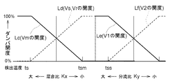
ロータ式除湿装置10の運転下において、給気側温度センサ18の検出温度tsに基づき混合比調整用モータダンパVs,Vr,Vmの開度及び分流比調整用ダンパV1,V2の開度を図3に示す如き設定相関ラインLc〜Lfに従って調整することで前記混合比Kx及び前記分流比Kyを調整して、乾燥炉1に供給する混合外気OA′の温度tsを設定給気温度tss(例えば、tss=40℃)に調整する。
(D) Supply air temperature control Under the operation of the
即ち、給気側温度センサ18の検出温度tsが所定の閾温度tsmより低い状態(ts≦tsm)では、モータダンパV1を100%開度(全開)にするとともにモータダンパV2を0%開度(全閉)にする。
That is, when the detected temperature ts of the supply
そして、この状態において、給気側温度センサ18の検出温度tsが低くなるほど、モータダンパVs,Vrの開度を減少させるとともに、これに背反させてモータダンパVmの開度を増大させることで前記混合比Kxを増大させ、これにより、前記混合による予熱での混合外気OA′の予熱度を増大させて乾燥炉1に供給する混合外気OA′の温度tsを上昇側に調整する。
In this state, the lower the detected temperature ts of the supply
また逆に、給気側温度センサ18の検出温度tsが高くなるほど、モータダンパVs,Vrの開度を増大させるとともに、これに背反させてモータダンパVmの開度を減少させることで前記混合比Kxを減少させ、これにより前記混合による予熱での混合外気OA′の予熱度を低下させて乾燥炉1に供給する混合外気OA′の温度tsを低下側に調整する。
Conversely, as the detected temperature ts of the supply
一方、給気側温度センサ18の検出温度tsが所定の閾温度tsmより高い状態(ts>tsm)では、モータダンパVs,Vrを100%開度(全開)にするとともに、モータダンパVmを0%開度(全閉)にする。
On the other hand, when the detected temperature ts of the supply
そして、この状態において、給気側温度センサ18の検出温度tsが低くなるほど、モータダンパV2の開度を減少させるとともに、これに背反させてモータダンパV1の開度を増大させることで前記分流比Kyを増大させ、これにより、処理域11の通過に伴う除湿ロータ13の回転による付随的な熱交換機能による混合外気OA′の追加予熱での予熱量を増大させて乾燥炉1に供給する混合外気OA′の温度tsを上昇側に調整する。
In this state, the lower the detected temperature ts of the supply
また逆に、給気側温度センサ18の検出温度tsが高くなるほど、モータダンパV2の開度を増大させるとともに、これに背反させてモータダンパV1の開度を減少させることで前記分流比Kyを減少させ、これにより、処理域11の通過に伴う除湿ロータ13の回転による付随的な熱交換機能による混合外気OA′の追加予熱での予熱量を減少させて乾燥炉1に送る混合外気OAの温度tsを低下側に調整する。
Conversely, as the detected temperature ts of the supply
つまり、このように混合比Kx及び分流比Kyを調整することで、導入外気OAの温度変化にかかわらず設定給気温度tssの低湿混合外気OA′を炉内換気用外気として乾燥炉1に安定的に供給する。 That is, by adjusting the mixing ratio Kx and the diversion ratio Ky in this way, the low-humidity mixed outside air OA ′ at the set supply air temperature tss is stabilized in the drying furnace 1 as the outside air for furnace ventilation regardless of the temperature change of the introduced outside air OA. To supply.
〔別実施形態〕
次に本発明の別実施形態を列記する。
[Another embodiment]
Next, other embodiments of the present invention will be listed.
前述の実施形態では、ロータ式除湿装置10の再生域12を通過した高温高湿空気RAを、導入外気OAに混合するものと、外部に排出するものとの2系統に分流する例を示したが、これに代え、再生域12を通過した高温高湿空気RAを、導入外気OAに混合するものと、熱交換手段により導入外気OAと顕熱交換させるものと、外部に排出するものとの3系統に分流するようにし、そして、それら3系統の各々における高温高湿空気RAの風量をダンパの開度調整などにより調整するようにしてもよい。
In the above-described embodiment, an example in which the high-temperature and high-humidity air RA that has passed through the
前述の実施形態では、ロータ式除湿装置10の運転において除湿ロータ13の回転速度は一定速度に固定する例を示したが、これに代え、外気OAの状態変化に応じて前記混合比Kxや前記分流比Kyを調整することに加えて、除湿ロータ13の回転速度も外気OAの状態変化に応じて調整するようにしてもよい。
In the above-described embodiment, the example in which the rotational speed of the
また、前述の実施形態では、ロータ式除湿装置10の処理域11に通過させる混合外気OA′と給気側バイパス風路15を通過させて処理域11を迂回させる混合外気OA′との分流比Kzを一定値に固定しておく例を示したが、これに代え、外気OAの状態変化に応じて前記混合比Kxや前記分流比Kyを調整することに加えて、この給気側の分流比Kzも外気OAの状態変化に応じて調整するようにしてもよい。
In the above-described embodiment, the split flow ratio between the mixed outside air OA ′ that passes through the
給気湿度制御として、湿度センサ17による検出湿度xsに基づき前記混合比Kxを調整することで乾燥炉1に供給する混合外気OA′の湿度xsを設定給気湿度xssに調整するのに、検出湿度xsと設定給気湿度xssとの偏差に応じた一般的なPID制御により前記混合比Kxを調整するようにするなど、給気湿度制御における混合比Kxの調整には種々の調整方式を採用することができる。
As supply air humidity control, by adjusting the mixing ratio Kx based on the detected humidity xs by the
また同様に、給気温度制御として、給気側温度センサ18による検出温度tsに基づき前記混合比Kxや前記分流比Kyを調整することで乾燥炉1に供給する混合外気OA′の温度tsを設定給気温度tssに調整するのに、検出温度tsと設定給気温度tssとの偏差に応じた一般的なPID制御により前記混合比Kxや前記分流比Kyを調整するようにするなど、給気温度制御における混合比Kxの調整や分流比Kyの調整にも種々の調整方式を採用することができる。
Similarly, as the supply air temperature control, the temperature ts of the mixed outside air OA ′ supplied to the drying furnace 1 is adjusted by adjusting the mixing ratio Kx and the diversion ratio Ky based on the temperature ts detected by the supply-
乾燥炉1の炉内で乾燥させる処理物Wは電極シートに限られるものではなく、炉内の高温化及び低湿化により乾燥し得るものであればどのようなものであってもよい。 The processed product W to be dried in the furnace of the drying furnace 1 is not limited to the electrode sheet, and any material can be used as long as it can be dried by increasing the temperature and decreasing the humidity in the furnace.
本発明による乾燥炉設備は、各種分野における種々の物品・物質の乾燥処理に利用することができる。 The drying furnace equipment according to the present invention can be used for drying various articles and substances in various fields.
1 乾燥炉
4 加熱手段
5,5a,7 炉内換気用の給気手段
RA 高温高湿空気
8,8a,9 炉内換気用の排気手段
13 除湿ロータ
11 処理域
12 再生域
10 ロータ式の除湿装置
OA 導入外気
OA′ 混合外気
16,7,9 混合手段
Kx 混合比
Vs,Vr,Vm 混合比調整手段
22 制御手段
17 湿度センサ
xs 検出湿度
xss 設定給気湿度
18 温度センサ
ts 検出温度
tss 設定給気温度
14 バイパス路
Ky 分流比
V1,V2 分流比調整手段
DESCRIPTION OF SYMBOLS 1
Claims (4)
この加熱手段による炉内加熱に併行して炉内換気用の外気を前記乾燥炉に供給する炉内換気用の給気手段と、
この給気手段による外気供給に併行して前記乾燥炉の炉内における高温高湿空気を外部に排出する炉内換気用の排気手段とを備える乾燥炉設備であって、
吸湿剤を保持する通気性の除湿ロータを処理域と再生域とに跨らせた状態で回転させてロータ各部を前記処理域と前記再生域とに交互に繰り返して位置させるロータ式の除湿装置を設け、
前記排気手段は、前記乾燥炉の炉内における高温高湿空気を再生用空気として前記再生域に通過させて外部に排出する構成にし、
前記再生域を通過した高温高湿空気の一部又は全部を前記給気手段による外部からの導入外気に混合して加湿及び予熱した状態の混合外気を生成する混合手段を設け、
この混合手段により混合する導入外気と高温高湿空気との混合比を調整する混合比調整手段を設け、
前記給気手段は、炉内換気用の外気として、前記混合手段により生成した混合外気を前記処理域に通過させて除湿した状態で前記乾燥炉に供給する構成にしてある乾燥炉設備。 Heating means for heating the inside of the drying furnace;
In-furnace ventilation air supply means for supplying outside air for furnace ventilation to the drying furnace in parallel with heating in the furnace by the heating means,
A drying furnace facility comprising exhaust means for ventilating the inside of the furnace for discharging high-temperature and high-humidity air in the furnace of the drying furnace in parallel with external air supply by the air supply means,
A rotor-type dehumidifier that rotates a breathable dehumidifying rotor holding a moisture absorbent in a state of straddling the treatment area and the regeneration area, and alternately and repeatedly positions each part of the rotor in the treatment area and the regeneration area. Provided,
The exhaust means is configured to pass the high-temperature and high-humidity air in the furnace of the drying furnace to the outside as the regeneration air and exhaust it to the outside.
A mixing means is provided that mixes a part or all of the high-temperature and high-humidity air that has passed through the regeneration zone with outside air introduced from the outside by the air supply means to generate humidified and preheated mixed outside air,
A mixing ratio adjusting means for adjusting the mixing ratio of the introduced outside air mixed with the mixing means and the high temperature and high humidity air is provided,
The drying furnace equipment, wherein the air supply means is configured to supply the outside air generated by the mixing means to the drying furnace in a dehumidified state by passing it through the treatment area as outside air for furnace ventilation.
前記制御手段は、給気湿度制御として、前記湿度センサによる検出湿度に基づき前記混合比調整手段により前記混合比を調整することで前記処理域に通過させて除湿した混合外気の湿度を設定給気湿度に調整する構成にしてある請求項1記載の乾燥炉設備。 Provided with a control means for operating the mixing ratio adjusting means, and provided with a humidity sensor for detecting the humidity of the mixed outside air passed through the treatment area and dehumidified,
As the supply air humidity control, the control means sets the humidity of the mixed outside air that has been dehumidified by passing through the treatment area by adjusting the mixing ratio by the mixing ratio adjusting means based on the humidity detected by the humidity sensor. The drying furnace equipment according to claim 1, which is configured to be adjusted to humidity.
前記制御手段は、切り換え指令に応じて前記給気湿度制御と給気温度制御とを選択的に実行する構成にするとともに、
この給気温度制御では、前記温度センサによる検出温度に基づき前記混合比調整手段により前記混合比を調整することで前記処理域に通過させて除湿した混合外気の温度を設定給気温度に調整する構成にしてある請求項2記載の乾燥炉設備。 A temperature sensor for detecting the temperature of the mixed outside air that has been passed through the treatment area and dehumidified is provided,
The control means is configured to selectively execute the supply air humidity control and the supply air temperature control according to a switching command,
In this supply air temperature control, the temperature of the mixed outside air that has been dehumidified by passing through the processing zone is adjusted to the set supply air temperature by adjusting the mixing ratio by the mixing ratio adjusting means based on the temperature detected by the temperature sensor. The drying furnace equipment according to claim 2, which is configured.
このバイパス路に通過させる高温高湿空気と前記再生域に通過させる高温高湿空気との分流比を調整する分流比調整手段を設け、
前記制御手段は、前記給気温度制御の際、前記温度センサによる検出温度に基づき前記混合比調整手段及び前記分流比調整手段により前記混合比及び前記分流比を調整することで前記処理域に通過させて除湿した混合外気の温度を設定給気温度に調整する構成にしてある請求項3記載の乾燥炉設備。 While providing a bypass path for bypassing part or all of the high-temperature high-humidity air discharged from the drying furnace by the exhaust means to the regeneration area,
A diversion ratio adjusting means is provided for adjusting a diversion ratio between the high-temperature and high-humidity air that passes through the bypass passage and the high-temperature and high-humidity air that passes through the regeneration zone.
The control means passes through the processing area by adjusting the mixing ratio and the diversion ratio by the mixing ratio adjusting means and the diversion ratio adjusting means based on the temperature detected by the temperature sensor during the supply air temperature control. 4. The drying furnace equipment according to claim 3, wherein the temperature of the mixed outside air dehumidified is adjusted to the set supply air temperature.
Priority Applications (1)
| Application Number | Priority Date | Filing Date | Title |
|---|---|---|---|
| JP2012042063A JP5862880B2 (en) | 2012-02-28 | 2012-02-28 | Drying furnace equipment |
Applications Claiming Priority (1)
| Application Number | Priority Date | Filing Date | Title |
|---|---|---|---|
| JP2012042063A JP5862880B2 (en) | 2012-02-28 | 2012-02-28 | Drying furnace equipment |
Publications (2)
| Publication Number | Publication Date |
|---|---|
| JP2013178024A true JP2013178024A (en) | 2013-09-09 |
| JP5862880B2 JP5862880B2 (en) | 2016-02-16 |
Family
ID=49269825
Family Applications (1)
| Application Number | Title | Priority Date | Filing Date |
|---|---|---|---|
| JP2012042063A Active JP5862880B2 (en) | 2012-02-28 | 2012-02-28 | Drying furnace equipment |
Country Status (1)
| Country | Link |
|---|---|
| JP (1) | JP5862880B2 (en) |
Cited By (5)
| Publication number | Priority date | Publication date | Assignee | Title |
|---|---|---|---|---|
| JP2018169066A (en) * | 2017-03-29 | 2018-11-01 | 東レ株式会社 | Hot air circulation drying device, drying method, and carbon fiber bundle manufacturing method |
| KR20220067263A (en) * | 2020-11-17 | 2022-05-24 | 주식회사 엘지에너지솔루션 | Device for drying electrode compring humidifying part |
| JP2023513068A (en) * | 2020-09-10 | 2023-03-30 | エルジー エナジー ソリューション リミテッド | Electrode drying device and electrode drying method |
| JP2024524890A (en) * | 2022-05-19 | 2024-07-09 | エルジー エナジー ソリューション リミテッド | Method and system for drying battery components |
| JP2024545105A (en) * | 2022-05-04 | 2024-12-05 | エルジー エナジー ソリューション リミテッド | Electrode Drying Equipment |
Families Citing this family (1)
| Publication number | Priority date | Publication date | Assignee | Title |
|---|---|---|---|---|
| JP2025114189A (en) * | 2024-01-24 | 2025-08-05 | 株式会社リコー | Intake and exhaust device, intake and exhaust system, and intake and exhaust method |
Citations (6)
| Publication number | Priority date | Publication date | Assignee | Title |
|---|---|---|---|---|
| JPS61255700A (en) * | 1985-05-07 | 1986-11-13 | 三鈴産業株式会社 | Drier for cleaning |
| US4926618A (en) * | 1989-01-03 | 1990-05-22 | Charles Ratliff | Industrial dehumidifier |
| JPH07124513A (en) * | 1993-10-29 | 1995-05-16 | Furukawa Electric Co Ltd:The | Equipment for continuous baking and drying of paint |
| JPH09329371A (en) * | 1996-06-07 | 1997-12-22 | Ebara Corp | Air conditioning system |
| JP2011125768A (en) * | 2009-12-15 | 2011-06-30 | Taikisha Ltd | Solvent recovery method and apparatus |
| JP2011255264A (en) * | 2010-06-07 | 2011-12-22 | Taikisha Ltd | Heat recovery type low humidity air supply system |
-
2012
- 2012-02-28 JP JP2012042063A patent/JP5862880B2/en active Active
Patent Citations (6)
| Publication number | Priority date | Publication date | Assignee | Title |
|---|---|---|---|---|
| JPS61255700A (en) * | 1985-05-07 | 1986-11-13 | 三鈴産業株式会社 | Drier for cleaning |
| US4926618A (en) * | 1989-01-03 | 1990-05-22 | Charles Ratliff | Industrial dehumidifier |
| JPH07124513A (en) * | 1993-10-29 | 1995-05-16 | Furukawa Electric Co Ltd:The | Equipment for continuous baking and drying of paint |
| JPH09329371A (en) * | 1996-06-07 | 1997-12-22 | Ebara Corp | Air conditioning system |
| JP2011125768A (en) * | 2009-12-15 | 2011-06-30 | Taikisha Ltd | Solvent recovery method and apparatus |
| JP2011255264A (en) * | 2010-06-07 | 2011-12-22 | Taikisha Ltd | Heat recovery type low humidity air supply system |
Cited By (11)
| Publication number | Priority date | Publication date | Assignee | Title |
|---|---|---|---|---|
| JP2018169066A (en) * | 2017-03-29 | 2018-11-01 | 東レ株式会社 | Hot air circulation drying device, drying method, and carbon fiber bundle manufacturing method |
| JP2023513068A (en) * | 2020-09-10 | 2023-03-30 | エルジー エナジー ソリューション リミテッド | Electrode drying device and electrode drying method |
| EP4084112A4 (en) * | 2020-09-10 | 2024-08-07 | LG Energy Solution, Ltd. | ELECTRODE DRYING DEVICE AND ELECTRODE DRYING METHOD |
| JP7546952B2 (en) | 2020-09-10 | 2024-09-09 | エルジー エナジー ソリューション リミテッド | Electrode drying device and electrode drying method |
| US12209805B2 (en) | 2020-09-10 | 2025-01-28 | Lg Energy Solution, Ltd. | Electrode drying device and electrode drying method |
| KR20220067263A (en) * | 2020-11-17 | 2022-05-24 | 주식회사 엘지에너지솔루션 | Device for drying electrode compring humidifying part |
| KR102872057B1 (en) * | 2020-11-17 | 2025-10-15 | 주식회사 엘지에너지솔루션 | Device for drying electrode compring humidifying part |
| JP2024545105A (en) * | 2022-05-04 | 2024-12-05 | エルジー エナジー ソリューション リミテッド | Electrode Drying Equipment |
| EP4435877A4 (en) * | 2022-05-04 | 2025-03-26 | LG Energy Solution, Ltd. | ELECTRODE DRYING APPARATUS |
| JP2024524890A (en) * | 2022-05-19 | 2024-07-09 | エルジー エナジー ソリューション リミテッド | Method and system for drying battery components |
| JP7754954B2 (en) | 2022-05-19 | 2025-10-15 | エルジー エナジー ソリューション リミテッド | Method and system for drying battery components |
Also Published As
| Publication number | Publication date |
|---|---|
| JP5862880B2 (en) | 2016-02-16 |
Similar Documents
| Publication | Publication Date | Title |
|---|---|---|
| JP5862880B2 (en) | Drying furnace equipment | |
| US10948202B2 (en) | Air conditioner capable of controlling heating and humidity, and control method therefor | |
| JP6325190B2 (en) | Desiccant unit control system and method | |
| KR101615168B1 (en) | Dehumidification system | |
| US10775059B2 (en) | Air conditioning capable of controlling ventilation and humidity, and control method therefor | |
| CN113218012B (en) | Anti-frosting fresh air heat recovery device and control method thereof | |
| JP4827906B2 (en) | A desiccant air conditioner that supplies dry air with an ultra-low dew point temperature without a purge zone. | |
| JP5669587B2 (en) | Low temperature regeneration desiccant air conditioner and operation method | |
| JP5686311B2 (en) | Gas removal system | |
| JP5679264B2 (en) | Heat recovery type low humidity air supply system | |
| KR20210141388A (en) | Dehumidification system including heat exchanger | |
| SE1850612A1 (en) | A partition device, an air treatment apparatus and a method, performed by a control device, for controlling an air treatment apparatus | |
| JPH0631132A (en) | Dry dehumidifier | |
| CN104344707B (en) | Dry furnace apparatus | |
| US20260110447A1 (en) | Operation control method of desiccant dehumidifier according to outside air temperature | |
| JP6898138B2 (en) | Desiccant type humidity control device and its control method | |
| KR100610671B1 (en) | Humidification device and ventilation system | |
| KR20230113700A (en) | Dehumidification system using counterflow in rotor | |
| KR102449592B1 (en) | Desiccant Dehumidification System | |
| KR20240049150A (en) | Air Cooled DehumidifiDryer | |
| JP2006162131A (en) | Dry dehumidifier | |
| JP5297289B2 (en) | Air conditioning system | |
| JP5899595B2 (en) | Low dew point air supply system | |
| JP2007170786A (en) | Ventilation system | |
| JP3123973B2 (en) | Humidity adjustment device |
Legal Events
| Date | Code | Title | Description |
|---|---|---|---|
| A621 | Written request for application examination |
Free format text: JAPANESE INTERMEDIATE CODE: A621 Effective date: 20141128 |
|
| A977 | Report on retrieval |
Free format text: JAPANESE INTERMEDIATE CODE: A971007 Effective date: 20150917 |
|
| A131 | Notification of reasons for refusal |
Free format text: JAPANESE INTERMEDIATE CODE: A131 Effective date: 20150929 |
|
| A521 | Request for written amendment filed |
Free format text: JAPANESE INTERMEDIATE CODE: A523 Effective date: 20151105 |
|
| TRDD | Decision of grant or rejection written | ||
| A01 | Written decision to grant a patent or to grant a registration (utility model) |
Free format text: JAPANESE INTERMEDIATE CODE: A01 Effective date: 20151201 |
|
| A61 | First payment of annual fees (during grant procedure) |
Free format text: JAPANESE INTERMEDIATE CODE: A61 Effective date: 20151215 |
|
| R150 | Certificate of patent or registration of utility model |
Ref document number: 5862880 Country of ref document: JP Free format text: JAPANESE INTERMEDIATE CODE: R150 |
|
| R250 | Receipt of annual fees |
Free format text: JAPANESE INTERMEDIATE CODE: R250 |
|
| R250 | Receipt of annual fees |
Free format text: JAPANESE INTERMEDIATE CODE: R250 |
|
| R250 | Receipt of annual fees |
Free format text: JAPANESE INTERMEDIATE CODE: R250 |
|
| R250 | Receipt of annual fees |
Free format text: JAPANESE INTERMEDIATE CODE: R250 |
|
| R250 | Receipt of annual fees |
Free format text: JAPANESE INTERMEDIATE CODE: R250 |
|
| R250 | Receipt of annual fees |
Free format text: JAPANESE INTERMEDIATE CODE: R250 |
|
| R250 | Receipt of annual fees |
Free format text: JAPANESE INTERMEDIATE CODE: R250 |
|
| R250 | Receipt of annual fees |
Free format text: JAPANESE INTERMEDIATE CODE: R250 |