JP2013188773A - Device and method for detecting positional deviation of workpiece and computer program - Google Patents
Device and method for detecting positional deviation of workpiece and computer program Download PDFInfo
- Publication number
- JP2013188773A JP2013188773A JP2012056277A JP2012056277A JP2013188773A JP 2013188773 A JP2013188773 A JP 2013188773A JP 2012056277 A JP2012056277 A JP 2012056277A JP 2012056277 A JP2012056277 A JP 2012056277A JP 2013188773 A JP2013188773 A JP 2013188773A
- Authority
- JP
- Japan
- Prior art keywords
- workpiece
- image
- mold
- unit
- imaging
- Prior art date
- Legal status (The legal status is an assumption and is not a legal conclusion. Google has not performed a legal analysis and makes no representation as to the accuracy of the status listed.)
- Granted
Links
Images

Landscapes
- Length Measuring Devices By Optical Means (AREA)
Abstract
【課題】 ワークの材質、色、形等により影響を受けることを従来に比して抑制した検出結果を得ることができるワークの位置ずれ検出装置、ワークの位置ずれ検出方法、及びコンピュータプログラムを提供する。
【解決手段】
プレス加工装置2内に装着された金型81を、金型81上にワーク100が配置された状態でカメラによって撮像する。撮像によって得られた画像から位置決めピンの像を含む部分画像を抽出し、当該部分画像と基準画像とのパターンマッチングを行い、類似度に基づいてワークの位置ずれを検出する。
【選択図】図3PROBLEM TO BE SOLVED: To provide a workpiece misalignment detection device, a workpiece misalignment detection method, and a computer program capable of obtaining a detection result in which the influence of the material, color, shape, etc. of the workpiece is suppressed as compared with the prior art To do.
[Solution]
The mold 81 mounted in the press working apparatus 2 is imaged by a camera in a state where the workpiece 100 is disposed on the mold 81. A partial image including an image of the positioning pin is extracted from the image obtained by imaging, pattern matching between the partial image and the reference image is performed, and a positional deviation of the workpiece is detected based on the similarity.
[Selection] Figure 3
Description
本発明は、金属板プレス加工の対象物であるワークの金型に対する位置ずれを検出するためのワークの位置ずれ検出装置、ワークの位置ずれ検出方法、及びコンピュータにワークの金型に対する位置ずれを検出させるためのコンピュータプログラムに関する。 The present invention relates to a workpiece misalignment detection apparatus, a workpiece misalignment detection method for detecting misalignment of a workpiece, which is an object of metal plate press processing, with respect to a die, and a computer. The present invention relates to a computer program for detection.
金属板のプレス加工においては、金型上にワーク(金属板)が設置された状態で加工が実行される。正常なプレス加工を行うためには、金型上の加工位置に正確にワークが設置される必要がある。つまり、金型上の加工位置からずれた位置にワークが設置された状態でプレス加工が行われると、不良品の発生、金型の損傷、プレス加工装置の故障等の不具合が発生することとなる。 In the press working of a metal plate, the work is executed in a state where a work (metal plate) is installed on a mold. In order to perform normal pressing, it is necessary to accurately place the workpiece at the processing position on the mold. In other words, if the press work is performed with the workpiece installed at a position shifted from the processing position on the mold, problems such as the occurrence of defective products, damage to the mold, and failure of the press processing apparatus may occur. Become.
特許文献1には、金型内に設置された鍛造素材の金型内における位置ずれを検出する位置ずれ検出装置が開示されている。特許文献1に開示されている位置ずれ検出装置は、赤熱素材(加熱されて赤熱状態になった鍛造素材)と赤熱素材を載置した下部金型とを複数のCCDカメラで様々な角度から撮像し、撮像により得られた画像に対して2値化処理等の画像処理を行い、撮像された赤熱素材の画像内での位置を特定する。さらにこの位置ずれ検出装置は、予め正常な位置に載置された赤熱素材を撮像した画像から赤熱素材の基準位置を定めておき、特定された赤熱素材の位置と基準位置との差異をずれとして検出する。
Japanese Patent Application Laid-Open No. 2004-151561 discloses a misalignment detection device that detects misalignment of a forging material installed in a mold within the mold. The misregistration detection device disclosed in
上記のように、特許文献1に開示されている位置ずれ検出装置にあっては、画像処理によりワークである赤熱素材の位置を特定している。しかしながら、個々のワークは同一の原料から構成されているとしても、色、形等に個体差が存在するため画像処理により正確にワークの位置を特定することができない場合がある。このようなワークの位置の特定の失敗は、ワークの位置ずれの誤検出の原因となる。
As described above, in the position shift detection device disclosed in
本発明は斯かる事情に鑑みてなされたものであり、その主たる目的は、上記課題を解決することができるワークの位置ずれ検出装置、ワークの位置ずれ検出方法、及びコンピュータプログラムを提供することにある。 The present invention has been made in view of such circumstances, and a main object of the present invention is to provide a workpiece displacement detection apparatus, a workpiece displacement detection method, and a computer program that can solve the above-described problems. is there.
上述した課題を解決するために、本発明の一の態様のワークの位置ずれ検出装置は、プレス加工装置内に設置された金型上にワークが設置されているときに、ワークと当接することによりワークを位置決めするために前記金型に設けられた位置決め部を撮像可能な位置に配置された撮像部と、前記金型上にワークが設置されている場合に前記撮像部が前記位置決め部を撮像することにより得られた画像に基づいて、前記金型上におけるワークの位置ずれを検出する画像処理部と、を備える。 In order to solve the above-described problem, the workpiece displacement detection device according to one aspect of the present invention is in contact with a workpiece when the workpiece is placed on a mold installed in the press working device. An imaging unit disposed at a position where the positioning unit provided on the mold can be imaged in order to position the workpiece, and when the workpiece is installed on the mold, the imaging unit moves the positioning unit. An image processing unit that detects a displacement of a workpiece on the mold based on an image obtained by imaging.
この態様において、前記画像処理部は、前記画像において前記位置決め部の少なくとも一部がワークに隠れているか否かを判別することにより、前記金型上におけるワークの位置ずれを検出するように構成されていてもよい。 In this aspect, the image processing unit is configured to detect a positional deviation of the workpiece on the mold by determining whether or not at least a part of the positioning unit is hidden in the workpiece in the image. It may be.
また、上記態様において、前記画像処理部は、ワークが前記金型に正常に設置されているときの前記位置決め部の画像である基準画像と、前記撮像部により得られた画像とを比較することにより、前記画像において前記位置決め部の少なくとも一部がワークに隠れているか否かを判別するように構成されていてもよい。 In the above aspect, the image processing unit compares a reference image, which is an image of the positioning unit when a workpiece is normally placed on the mold, with an image obtained by the imaging unit. Accordingly, it may be configured to determine whether or not at least a part of the positioning portion is hidden in the workpiece in the image.
また、上記態様において、前記撮像部は、前記金型上に設置されたワークの端縁を含む撮像範囲で撮像を行うように構成されており、前記画像処理部は、前記撮像部により得られた画像において前記ワークの端縁が所定位置にあるか否かを判別することにより、前記金型上におけるワークの位置ずれを検出するように構成されていてもよい。 In the above aspect, the imaging unit is configured to perform imaging in an imaging range including an edge of a workpiece installed on the mold, and the image processing unit is obtained by the imaging unit. Further, it may be configured to detect displacement of the workpiece on the mold by determining whether or not the edge of the workpiece is at a predetermined position in the image.
また、上記態様において、前記画像処理部は、ワークが前記金型に正常に設置されているときの前記位置決め部の画像である基準画像と、前記撮像部により得られた画像とを比較することにより、前記画像において前記ワークの端縁が所定位置にあるか否かを判別するように構成されていてもよい。 In the above aspect, the image processing unit compares a reference image, which is an image of the positioning unit when a workpiece is normally placed on the mold, with an image obtained by the imaging unit. Thus, it may be configured to determine whether or not the edge of the workpiece is in a predetermined position in the image.
また、上記態様において、前記撮像部は、撮像範囲が互いに異なる第1撮像部及び第2撮像部を具備し、前記ワークの位置ずれ検出装置は、入力部をさらに備え、前記画像処理部は、第1の金型の使用を示す第1金型情報が前記入力部に与えられたときは、前記第1撮像部により得られた画像に基づいて、前記第1の金型上におけるワークの位置ずれを検出し、前記第1の金型とは異なる第2の金型の使用を示す第2金型情報が前記入力部に与えられたときは、前記第2撮像部により得られた画像に基づいて、前記第2の金型上におけるワークの位置ずれを検出するように構成されていてもよい。 Further, in the above aspect, the imaging unit includes a first imaging unit and a second imaging unit having different imaging ranges, the workpiece displacement detection device further includes an input unit, and the image processing unit includes: When the first mold information indicating the use of the first mold is given to the input unit, the position of the workpiece on the first mold based on the image obtained by the first imaging unit. When the second mold information indicating the use of the second mold different from the first mold is detected and given to the input unit, an image obtained by the second imaging unit is displayed. Based on this, the position deviation of the workpiece on the second mold may be detected.
また、上記態様において、前記ワークの位置ずれ検出装置は、前記撮像部により得られた画像と、前記位置決め部の少なくとも一部がワークに隠れているか否かの判別結果を示す情報とを含む位置ずれ検出結果画面を表示する表示部をさらに備えていてもよい。 Further, in the above aspect, the workpiece displacement detection device includes a position including an image obtained by the imaging unit and information indicating a determination result as to whether or not at least a part of the positioning unit is hidden behind the workpiece. You may further provide the display part which displays a shift | offset | difference detection result screen.
また、上記態様において、前記表示部は、前記位置ずれ検出結果画面において、前記撮像部により得られた画像に、ワークに隠れているか否かの判別を実行した前記位置決め部の像を指示する図形を重ねて表示し、前記図形で指示された前記位置決め部の少なくとも一部がワークに隠れているか否かの判別結果を示す情報を表示するように構成されていてもよい。 Further, in the above aspect, the display unit is a graphic designating an image of the positioning unit that has performed the determination as to whether or not the image obtained by the imaging unit is hidden behind a workpiece on the misalignment detection result screen. May be displayed so as to display information indicating a determination result as to whether or not at least a part of the positioning unit indicated by the graphic is hidden behind the workpiece.
また、上記態様において、前記ワークの位置ずれ検出装置は、プレス加工装置へワークを搬送するための搬送路において、搬送中のワークを撮像するラインスキャンカメラと、前記ラインスキャンカメラによって得られたワークの画像に対して二値化処理を実行し、前記二値化処理により得られた二値化画像に基づいて前記ワーク上の異物を検出する第2画像処理部と、をさらに備えていてもよい。 Further, in the above aspect, the workpiece displacement detection device includes: a line scan camera that images a workpiece being conveyed in a conveyance path for conveying the workpiece to a press working device; and a workpiece obtained by the line scan camera. A second image processing unit that executes a binarization process on the image and detects foreign matter on the workpiece based on the binarized image obtained by the binarization process. Good.
また、本発明の一の態様のワークの位置ずれ検出方法は、プレス加工装置内に設置された金型上にワークが正常に設置されているときに、ワークと当接することによりワークを位置決めするために前記金型に設けられた位置決め部を撮像可能な位置に配置された撮像部により、前記金型上にワークが設置されている時点で前記位置決め部を撮像するステップと、撮像により得られた画像に基づいて、前記金型上におけるワークの位置ずれを検出するステップと、を有する。 The workpiece displacement detection method according to one aspect of the present invention positions a workpiece by contacting the workpiece when the workpiece is normally installed on a mold installed in a press working apparatus. In order to obtain an image of the positioning unit provided at the position where the positioning unit provided on the mold can be imaged, and when the workpiece is installed on the mold, Detecting a positional deviation of the workpiece on the mold based on the obtained image.
また、本発明の一の態様のコンピュータプログラムは、プレス加工装置内に設置された金型に対するワークの位置ずれをコンピュータに検出させるためのコンピュータプログラムであって、前記金型上にワークが正常に設置されているときに、ワークと当接することによりワークを位置決めするために前記金型に設けられた位置決め部を撮像可能な位置から、前記金型上にワークが設置されている時点で前記位置決め部を撮像することにより得られた画像を取得するステップと、取得された画像に基づいて、前記金型上におけるワークの位置ずれを検出するステップと、を前記コンピュータに実行させる。 A computer program according to an aspect of the present invention is a computer program for causing a computer to detect a positional deviation of a workpiece with respect to a mold installed in a press working apparatus, wherein the workpiece is normally placed on the mold. When the workpiece is installed on the mold from the position where the positioning portion provided on the mold can be imaged to position the workpiece by contacting the workpiece when installed. Causing the computer to execute a step of acquiring an image obtained by imaging the part and a step of detecting a positional deviation of the workpiece on the mold based on the acquired image.
本発明に係るワークの位置ずれ検出装置、ワークの位置ずれ検出方法、及びコンピュータプログラムによれば、ワークの個体差に起因するワークの位置ずれの誤検出を防止することができる。 According to the workpiece positional deviation detection apparatus, the workpiece positional deviation detection method, and the computer program according to the present invention, it is possible to prevent erroneous detection of the workpiece positional deviation caused by individual differences between workpieces.
以下、本発明の好ましい実施の形態を、図面を参照しながら説明する。 Hereinafter, preferred embodiments of the present invention will be described with reference to the drawings.
[プレス加工システムの構成]
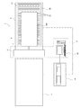
図1は、本実施の形態に係るプレス加工システムの全体構成を示す平面図である。プレス加工システム1は、プレス加工装置2と、プレス加工装置2へワークを搬送するためのワーク搬送装置3と、プレス加工装置2及びワーク搬送装置3の動作制御を行うためのプレス制御装置4と、ワークの金型に対する位置ずれを検出するためのワーク異常検出装置5とを備えている。
[Configuration of press working system]
FIG. 1 is a plan view showing the overall configuration of the press working system according to the present embodiment. The
プレス加工装置2は、上型及び下型を有する金型を設置可能であり、下型の上に設置された金属板(鋼板、アルミニウム合金板、チタン合金板等)のワーク100に対して曲げプレス加工を行う構成となっている。
The
ワーク搬送装置3は、ワーク100をプレス加工装置2へ搬送する。ワーク100は、ワーク搬送装置3に設置されたワーク搬送台31上に水平に載置される。ワーク搬送台31には、板状の台座32の上に、長手方向が水平となるように複数のローラ33,33,…が互いに平行に配置されており、これらのローラ33,33,…上にワーク100が載置される。ワーク搬送装置3は、ワーク搬送台31を図中に矢印で示すX方向へ移動することにより、ワーク100を搬送するようになっている。
The
プレス制御装置4は、プレス加工装置2と通信可能に接続されており、プレス加工装置2を動作制御することが可能である。ワーク搬送装置3がワーク100をプレス加工装置2へ搬送し、ワーク100が下型上に配置された時点で、プレス制御装置4の制御により、プレス加工装置2がワーク100に対してプレス加工を実行する。プレス加工装置2からワーク100が排出されると、これと同時に、次に加工されるワーク100がワーク搬送装置3により搬送され、プレス加工装置2へ供給される。このような動作を繰り返し実行するように、プレス制御装置4がプレス加工装置2及びワーク搬送装置3を制御する。
The press control device 4 is communicably connected to the
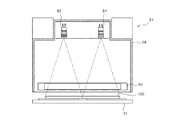
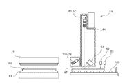
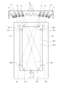
次に、ワーク異常検出装置5の構成について説明する。ワーク異常検出装置5は、ワーク搬送装置3に取り付けられた撮像ユニット51と、コンピュータにより構成された画像処理ユニット52とを具備している。図2は、撮像ユニット51の構成を示す正面断面図であり、図3は、その側面断面図である。図2及び図3に示すように、撮像ユニット51は、内部に第1カメラ61と、第2カメラ62と、照明ユニット63とが収容されたハウジング64を備えている。ハウジング64はワーク搬送装置3の搬送路の上方に配置され、下端が開口している。また、ハウジング64の内壁は光の乱反射防止のために艶消し黒塗装がされ、ハウジング64の内部では、第1カメラ61及び第2カメラ62が、前記開口を通じてワーク搬送装置3の搬送路を撮像可能なように、撮像方向を下方にして配置されている。また、図2に示すように、第1カメラ61及び第2カメラ62は、ワーク搬送装置3の搬送方向(図1におけるX方向)に対して直行する方向に並べて配置されている。つまり、第1カメラ61が、ワーク搬送装置3によって搬送されるワークの幅方向の右半分を撮像し、第2カメラ62が、前記ワークの幅方向の左半分を撮像するように構成されている。
Next, the configuration of the workpiece
照明ユニット63は、照度ムラの発生を防止するため、高周波点灯が可能な一方向に長い蛍光灯であり、その長手方向が、ワーク搬送装置3の搬送方向(図1におけるX方向)に対して直行する方向に沿うように配置されている。照明ユニット63の長さはワーク100の幅よりも大きく、ワーク搬送装置3によって搬送されるワーク100の幅方向の全体に亘って光を照射可能となっている。また、照明ユニット63の光の照射方向は、図3に示すように、ワーク搬送装置3の搬送方向に対して45°傾斜している。また、第1カメラ61及び第2カメラ62は、ワーク100の照明ユニット63により光が照射された部分を撮像するように、照明ユニット63に対して位置決めされている。これにより、照明ユニット63によって照射された光がワーク100の表面で散乱した散乱光が第1カメラ61及び第2カメラ62に入射し、照明ユニット63によって照射された光の全反射光は第1カメラ61及び第2カメラ62に入射しないこととなる。このため、第1カメラ61及び第2カメラ62の受光レベルが過剰に高い白飛びの現象を防止し、第1カメラ61及び第2カメラ62の受光レベルを適切な範囲とすることができる。また、ハウジング64は十分な遮蔽性を有しており、ハウジング64の内部への外乱光の進入が防止される。
The
第1カメラ61及び第2カメラ62のそれぞれは、ラインスキャンカメラである。また、ワーク搬送装置3はワーク100を一定速度で搬送する。第1カメラ61及び第2カメラ62のそれぞれの撮像範囲をワーク100が通過する間、第1カメラ61及び第2カメラ62が撮像を継続することで、サンプリング時間当たりに撮像された画素データ群が複数取得される。これらの画素データ群をつなぎ合わせることで、ワーク100の表面全体を撮像した画像が得られる。
Each of the
また、ハウジング64には、ワーク検出用の第1光学式センサ65及び第2光学式センサ66が取り付けられている。第1光学式センサ65及び第2光学式センサ66は、ハウジング64の開口よりも(つまり、第1カメラ61及び第2カメラ62の撮像領域よりも)、ワーク搬送装置3の搬送方向上流側に配置されている。また、第1光学式センサ65及び第2光学式センサ66は、第1光学式センサ65が第2光学式センサ66よりも前記搬送方向上流側に位置するように、前記搬送方向と平行に配置されている。第1光学式センサ65及び第2光学式センサ66のそれぞれは、フォトリフレクタであり、ワーク100の有無を検出することが可能である。
In addition, a first
ワーク100がワーク搬送装置3によって搬送されるとき、まずワーク100の先端が第1光学式センサ65の直下に進入する。これにより、第1光学式センサ65の出力信号がオフからオンに変化する。他方、第2光学式センサ66の直下にはワーク100がまだ存在していないので、第2光学式センサ66の出力信号はオフのままである。さらにワーク100が搬送されると、ワーク100の先端が第2光学式センサ66の直下に進入する。これにより、第2光学式センサ66の出力信号がオフからオンに変化する。このとき、第2光学式センサ66の近傍に配置された第1光学式センサ65の直下にもワーク100が存在するため、第1光学式センサ65の出力信号はオンのままである。つまり、第1光学式センサ65及び第2光学式センサ66の出力信号が、オン及びオフの組合せからオン及びオンの組合せに変化したことを検出することにより、ワーク100の先端を検出することができる。
When the
また、ワーク100が撮像領域を通過し終わるときには、ワーク100の後端が第1光学式センサ65の直下を通過する。これにより、第1光学式センサ65の出力信号がオンからオフに変化する。他方、第2光学式センサ66の直下にはワーク100がまだ存在しているので、第2光学式センサ66の出力信号はオンのままである。さらにワーク100が搬送されると、ワーク100の後端が第2光学式センサ66の直下を通過する。これにより、第2光学式センサ66の出力信号がオンからオフに変化する。このとき、第1光学式センサ65の直下にはワーク100が存在しないため、第1光学式センサ65の出力信号はオフのままである。つまり、第1光学式センサ65及び第2光学式センサ66の出力信号が、オフ及びオンの組合せからオフ及びオフの組合せに変化したことを検出することにより、ワーク100の後端を検出することができる。
When the
このようにしてワーク100の先端が検出された時点で第1カメラ61及び第2カメラ62による撮像が開始され、ワーク100の後端が検出された時点で第1カメラ61及び第2カメラ62による撮像が終了されることで、ワーク100の全体の画像が得られる。
When the leading edge of the
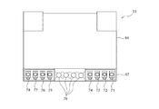
図4は、撮像ユニット51の構成を示す正面図である。撮像ユニット51は、ハウジング64の前記搬送方向下流側に設けられたハウジング67を備えている。ハウジング67は、ハウジング64の下端部に取り付けられた横長の直方体形状の筐体であり、前記搬送方向下流側の面が開口している。当該開口部には、塵・油等の侵入を防ぐために透明な合成樹脂製のカーテンが設けられている。
FIG. 4 is a front view showing the configuration of the
ハウジング67には、8個のエリアカメラ71〜78と、4つのハロゲンライト79が収容されている。撮像ユニット51は、プレス加工装置2より前記搬送方向上流側に配置されており、カメラ71〜78はかかるプレス加工装置2の内部の下型81を撮像可能な方向に向けて配置されている。また、ハロゲンライト79は、プレス加工装置2の内部の下型81に光を照射可能な方向に向けて配置されている。
The
ハウジング64の長手方向(即ち、前記搬送方向に直行する水平方向)の中央部には、4つのハロゲンライト79が配置されている。このハロゲンライト79が設置されている中央部よりも右方の空間には、カメラ71〜74が横に並べて配置されており、左方の空間には、カメラ75〜78が横に並べて配置されている。
Four
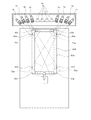
図5及び図6は、カメラ71〜78の撮像範囲を模式的に説明する平面図である。プレス加工装置2には、様々な金型が設置される。本実施の形態に係るプレス加工装置2は、大型の加工製品を製造するための金型81aと、小型の加工製品を製造するための金型81bとを選択的に装着可能である。
5 and 6 are plan views schematically illustrating the imaging range of the
図5に示すように、金型81aがプレス加工装置2に装着されているときは、4つのカメラ72,74,75,77が使用される。金型81aには、大型のワーク100aを位置決めするための位置決めピン82a〜82hが設けられている。位置決めピン82a〜82hは、ワーク100aに当接することでワーク100aを金型81a上の正常な位置に位置決めするために下型81aの上面から突設された円柱状の部品である。カメラ72は、位置決めピン82a及び82bが含まれる撮像領域72aについて撮像可能なようにハウジング67に取り付けられている。カメラ74は、位置決めピン82c及び82dが含まれる撮像領域74aについて撮像可能なようにハウジング67に取り付けられている。同様に、カメラ75は、位置決めピン82g及び82hが含まれる撮像領域75aについて撮像可能なようにハウジング67に取り付けられており、カメラ77は、位置決めピン82e及び82fが含まれる撮像領域77aについて撮像可能なようにハウジング67に取り付けられている。
As shown in FIG. 5, when the
図6に示すように、金型81bがプレス加工装置2に装着されているときは、4つのカメラ71,73,76,78が使用される。金型81bには、小型のワーク100bを位置決めするための位置決めピン83a〜83hが設けられている。位置決めピン83a〜83hは、ワーク100bに当接することでワーク100bを金型81b上の正常な位置に位置決めするために下型81bの上面から突設された円柱状の部品である。カメラ71は、位置決めピン83a及び83bが含まれる撮像領域71aについて撮像可能なようにハウジング67に取り付けられている。カメラ73は、位置決めピン83c及び83dが含まれる撮像領域73aについて撮像可能なようにハウジング67に取り付けられている。同様に、カメラ76は、位置決めピン83g及び83hが含まれる撮像領域76aについて撮像可能なようにハウジング67に取り付けられており、カメラ78は、位置決めピン83e及び83fが含まれる撮像領域78aについて撮像可能なようにハウジング67に取り付けられている。
As shown in FIG. 6, when the
上記ような使用カメラの切り替えは、画像処理ユニット52により行われる。また、第1カメラ61及び第2カメラ62並びにカメラ71〜78によって得られた画像は、画像処理ユニット52に与えられ、画像処理ユニット52により処理される。
The above-described camera switching is performed by the
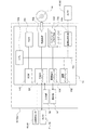
図7は、画像処理ユニット52の構成を示すブロック図である。画像処理ユニット52は、コンピュータ52aによって実現される。図7に示すように、コンピュータ52aは、本体53と、表示部54と、入力部55とを備えている。本体53は、CPU53a、ROM53b、RAM53c、ハードディスク53d、読出装置53e、入出力インタフェース53f、通信インタフェース53g、画像出力インタフェース53h、及び画像生成回路53kを備えており、CPU53a、ROM53b、RAM53c、ハードディスク53d、読出装置53e、入出力インタフェース53f、通信インタフェース53g、画像出力インタフェース53h、及び画像生成回路53kは、バス53jによって接続されている。
FIG. 7 is a block diagram showing a configuration of the
CPU53aは、RAM53cにロードされたコンピュータプログラムを実行することが可能である。そして、ワークの位置ずれ検出用のコンピュータプログラム56aを当該CPU53aが実行することにより、コンピュータ52aが画像処理ユニット52として機能する。
The
ROM53bは、マスクROM、PROM、EPROM、又はEEPROM等によって構成されており、CPU53aに実行されるコンピュータプログラム及びこれに用いるデータ等が記録されている。
The
RAM53cは、SRAMまたはDRAM等によって構成されている。RAM53cは、ハードディスク53dに記録されているコンピュータプログラム56aの読み出しに用いられる。また、CPU53aがコンピュータプログラムを実行するときに、CPU53aの作業領域として利用される。
The
ハードディスク53dは、オペレーティングシステム及びアプリケーションプログラム等、CPU53aに実行させるための種々のコンピュータプログラム及び当該コンピュータプログラムの実行に用いられるデータがインストールされている。サーバ用のコンピュータプログラム56aも、このハードディスク53dにインストールされている。
The
読出装置53eは、フレキシブルディスクドライブ、CD−ROMドライブ、またはDVD−ROMドライブ等によって構成されており、可搬型記録媒体56に記録されたコンピュータプログラムまたはデータを読み出すことができる。また、可搬型記録媒体56には、コンピュータを画像処理ユニット52として機能させるためのコンピュータプログラム56aが格納されており、コンピュータ52aが当該可搬型記録媒体56からコンピュータプログラム56aを読み出し、当該コンピュータプログラム56aをハードディスク53dにインストールすることが可能である。
The
なお、前記コンピュータプログラム56aは、可搬型記録媒体56によって提供されるのみならず、電気通信回線(有線、無線を問わない)によってコンピュータ52aと通信可能に接続された外部の機器から前記電気通信回線を通じて提供することも可能である。例えば、前記コンピュータプログラム56aがインターネット上のサーバコンピュータのハードディスク内に格納されており、このサーバコンピュータにコンピュータ52aがアクセスして、当該コンピュータプログラムをダウンロードし、これをハードディスク53dにインストールすることも可能である。
The
また、ハードディスク53dには、例えば米マイクロソフト社が製造販売するWindows(登録商標)等のマルチタスクオペレーティングシステムがインストールされている。以下の説明においては、本実施の形態に係るコンピュータプログラム56aは当該オペレーティングシステム上で動作するものとしている。
The
入出力インタフェース53fは、例えばUSB,IEEE1394,又はRS-232C等のシリアルインタフェース、SCSI,IDE,又は IEEE1284等のパラレルインタフェース、及びD/A変換器、A/D変換器等からなるアナログインタフェース等から構成されている。入出力インタフェース53fには、キーボード及びマウスからなる入力部55が接続されており、ユーザが当該入力部55を使用することにより、コンピュータ52aにデータを入力することが可能である。
The input /
また、入出力インタフェース53fには、撮像ユニット51に設けられたカメラ71〜78が通信可能に接続されている。これにより、画像処理ユニット52によってカメラ71〜78が制御され、また、画像データがカメラ71〜78から画像処理ユニット52へ出力される。
In addition,
また、入出力インタフェース53fには、撮像ユニット51に設けられた第1光学式センサ65及び第2光学式センサ66が通信可能に接続されている。これにより、第1光学式センサ65及び第2光学式センサ66の出力信号が、画像処理ユニット52に与えられる。
In addition, a first
通信インタフェース53gは、Ethernet(登録商標)インタフェースである。通信インタフェース53gはプレス制御装置4に接続されている。コンピュータ52aは、通信インタフェース53gにより、所定の通信プロトコルを使用してプレス制御装置4との間でデータの送受信が可能である。
The
画像出力インタフェース53hは、LCDまたはCRT等で構成された表示部54に接続されており、CPU53aから与えられた画像データに応じた映像信号を表示部54に出力するようになっている。表示部54は、入力された映像信号にしたがって、画像(画面)を表示する。
The
画像生成回路53kは、FPGA等の画像処理チップを有して構成されている。かかる画像生成回路53kは、第1カメラ61及び第2カメラ62のそれぞれと通信可能に接続されている。これにより、画像生成回路53kは、第1カメラ61から出力された画像信号を受信して、ワーク表面の右側半分の画像を生成し、第2カメラ62から出力された画像信号を受信して、ワーク表面の左側半分の画像を生成することが可能である。このようにして生成された画像は、CPU53aに与えられる。
The
[プレス加工システムの動作]
以下、本実施の形態に係るプレス加工システム1の動作について説明する。
[Operation of press working system]
Hereinafter, the operation of the
<初期化処理>
プレス加工システム1によるプレス加工動作を開始する前に、まずオペレータは使用する金型をプレス加工装置2に装着し、この金型を特定する金型情報をプレス制御装置4に入力する。これにより、プレス制御装置4が金型情報を記憶する。次に、プレス加工装置2に装着された金型に適合したワーク100がワーク搬送装置3に供給される。上述したように、加工製品に応じて、使用する金型が決定され、各金型はサイズ及び位置決めピンの設置位置等が異なる。また、ワークは金属板であり、その素材金属の種類は加工製品に応じて異なる。従って、鋼板のワークが供給される場合もあれば、チタン合金のワークが供給される場合もある。
<Initialization process>
Before starting the press working operation by the
本実施の形態に係るワーク異常検出装置5は、プレス加工対象のワークが搬送されている途中で、ワークに付着した異物を検出するための異物検出処理を実行する。上述したように、加工製品に応じて様々な金属素材からなるワークがワーク搬送装置3によって搬送される。金属は種類によって色が異なり、また、ワークのロットによっても微妙に色が異なる場合がある。ワークを撮像して得られた画像を処理して正確に異物検出を行うためには、そのワークの色に適応した設定値を用いる必要がある。このため、まずロット毎にワークのサンプルが準備され、このサンプルの表面に付着した異物がオペレータによって除去される。異物が除去されたサンプルがワーク搬送装置3によって搬送され、このサンプルを用いて異物検出用の設定値を決定する異物検出初期化処理がワーク異常検出装置5によって実行される。
The workpiece
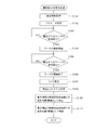
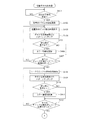
以下、異物検出初期化処理について説明する。図8は、異物検出初期化処理の手順を示すフローチャートである。まず、プレス制御装置4から金型情報が画像処理ユニット52に送信される。画像処理ユニット52のCPU53aは、プレス制御装置4から送信された金型情報を取得し(ステップS101)、この金型情報に対応するパラメータ(画像処理の判定エリア及びワークのサイズ情報等)をハードディスク53dに設けられた設定値データベース(図示せず)から読み出し、設定値としてRAM53c又はハードディスク53dに記憶する(ステップS102)。
Hereinafter, the foreign object detection initialization process will be described. FIG. 8 is a flowchart showing the procedure of foreign object detection initialization processing. First, mold information is transmitted from the press control device 4 to the
次に、CPU53aは、第1光学式センサ65及び第2光学式センサ66の出力信号に基づいて、ワークのサンプルの先端が検出されたか否かを判別する(ステップS103)。ステップS103の処理においては、第1光学式センサ65及び第2光学式センサ66の出力信号が、オン及びオフの組合せからオン及びオンの組合せに変化した場合に、ワークのサンプルの先端が検出される。ステップS103において、ワークのサンプルの先端が検出されなかった場合には(ステップS103においてNO)、CPU53aは、ワークのサンプルの先端が検出されるまでステップS103の処理を繰り返す。
Next, the
ステップS103においてワークのサンプルの先端が検出された場合には(ステップS103においてYES)、CPU53aは、第1カメラ61及び第2カメラ62によるワークのサンプルの撮像を開始する(ステップS104)。これにより、第1カメラ61及び第2カメラ62からの出力信号が画像処理ユニット52に取り込まれ、ワークのサンプルの画像が生成される。
When the tip of the workpiece sample is detected in step S103 (YES in step S103), the
次に、CPU53aは、第1光学式センサ65及び第2光学式センサ66の出力信号に基づいて、ワークのサンプルの後端が検出されたか否かを判別する(ステップS105)。ステップS105の処理においては、第1光学式センサ65及び第2光学式センサ66の出力信号が、オン及びオンの組合せからオフ及びオンの組合せに変化した場合に、ワークのサンプルの後端が検出される。ステップS105において、ワークのサンプルの後端が検出されなかった場合には(ステップS105においてNO)、CPU53aは、ワークのサンプルの後端が検出されるまでステップS105の処理を繰り返す。
Next, the
ステップS105においてワークのサンプルの後端が検出された場合には(ステップS105においてYES)、CPU53aは、第1カメラ61及び第2カメラ62によるワークのサンプルの撮像を終了する(ステップS106)。これにより、画像処理ユニット装置52による第1カメラ61及び第2カメラ62からの出力信号の取り込みが完了し、ワークのサンプルの画像が完成する。
If the trailing edge of the workpiece sample is detected in step S105 (YES in step S105), the
上記のように生成されたワークのサンプルの画像は多階調のグレースケール画像(以下、「サンプル撮像画像」という。)である。CPU53aは、当該サンプル撮像画像に対して3×3空間フィルタによるノイズ除去処理を実行する(ステップS107)。次にCPU53aは、ノイズ除去処理後のサンプル撮像画像の輝度ヒストグラムを生成する(ステップS108)。なお、ここでいう輝度ヒストグラムとは、輝度ヒストグラムのグラフではなく、輝度毎に出現回数を計数したデータのことである。かかる輝度ヒストグラムは、RAM53c又はハードディスク53dに記憶される。
The sample image of the workpiece generated as described above is a multi-tone grayscale image (hereinafter referred to as “sampled image”). The
次にCPU53cは、輝度ヒストグラムから最大輝度を抽出し、この最大輝度と所定の明部感度余裕値との合計値を第1閾値として設定(RAM53c又はハードディスク53dに記憶)する(ステップS109)。この第1閾値は、ワークを撮像して得られた多階調のグレースケール画像において、異常に高輝度の部分を異物として検出するための閾値である。
Next, the
次にCPU53cは、輝度ヒストグラムから最小輝度を抽出し、この最小輝度と所定の暗部感度余裕値との差分値を第2閾値として設定(RAM53c又はハードディスク53dに記憶)する(ステップS109)。この第2閾値は、ワークを撮像して得られた多階調のグレースケール画像において、異常に低輝度の部分を異物として検出するための閾値である。ステップS109の処理の後、CPU53aは、異物検出初期化処理を終了する。
Next, the
上記のような異物検出初期化処理により、後の異物検出処理に用いられる設定値である第1閾値及び第2閾値が設定される。 By the foreign object detection initialization process as described above, the first threshold value and the second threshold value, which are set values used in the subsequent foreign object detection process, are set.
本実施の形態に係るワーク異常検出装置5は、プレス加工対象のワークがプレス加工装置2内の金型に設置された状態で、ワークの金型に対する位置ずれを検出するための位置ずれ検出処理を実行する。上述したように、加工製品に個別に対応した金型がプレス加工装置2に装着される。金型を撮像して得られた画像を処理して正確にワークの位置ずれ検出を行うためには、装着された金型に適合した処理を行う必要がある。このため、プレス加工装置2に金型が装着された場合には、プレス加工システム1によるプレス加工動作の準備として、位置ずれ検出の各種初期設定を行うための位置ずれ検出初期化処理がワーク異常検出装置5によって実行される。
The work
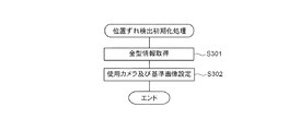
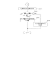
以下、位置ずれ検出初期化処理について説明する。図9は、位置ずれ検出初期化処理の手順を示すフローチャートである。上述したように、プレス制御装置4から金型情報が画像処理ユニット52に送信される。画像処理ユニット52のCPU53aは、プレス制御装置4から送信された金型情報を取得する(ステップS301)。このステップS301の処理は、上述したステップS101の処理と同じ処理である。
Hereinafter, the misregistration detection initialization process will be described. FIG. 9 is a flowchart showing the procedure of the misalignment detection initialization process. As described above, the mold information is transmitted from the press control device 4 to the
次にCPU53aは、カメラ71〜78のうち、受信した金型情報に対応する使用カメラを特定するデータ及びパターンマッチングに使用する基準画像(テンプレート)をハードディスク53dに設けられた設定値データベース(図示せず)から読み出し、設定値としてRAM53c又はハードディスク53dに記憶する(ステップS302)。これにより、例えば、図5に示す場合には、使用カメラとしてカメラ72,74,75,77が設定され、図6に示す場合には、使用カメラとしてカメラ71,73,76,78が設定される。また、基準画像については後述する。かかるステップS302の処理の後、CPU53aは位置ずれ検出初期化処理を終了する。
Next, the
<異物検出処理>
以上のような準備動作が完了した後、プレス加工システム1によるワークのプレス加工動作が開始される。このプレス加工動作では、ワーク搬送装置3によってプレス加工装置2までワークが搬送され、ワーク搬送装置3から搬出されたワークに対して、プレス加工装置2によって自動的にプレス加工が行われる。本実施の形態に係るプレス加工システム1にあっては、ワーク搬送装置3によるワークの搬送の途中で、ワーク異常検出装置5による異物検出処理が実行される。
<Foreign matter detection processing>
After the preparation operation as described above is completed, the press working operation of the workpiece by the
以下、異物検出処理について説明する。図10は、異物検出処理の手順を示すフローチャートである。まず、CPU53aは、第1光学式センサ65及び第2光学式センサ66の出力信号に基づいて、ワークの先端が検出されたか否かを判別する(ステップS201)。ステップS201の処理においては、第1光学式センサ65及び第2光学式センサ66の出力信号が、オン及びオフの組合せからオン及びオンの組合せに変化した場合に、ワークの先端が検出される。ステップS201において、ワークの先端が検出されなかった場合には(ステップS201においてNO)、CPU53aは、ワークの先端が検出されるまでステップS201の処理を繰り返す。
Hereinafter, the foreign object detection process will be described. FIG. 10 is a flowchart showing a procedure of foreign object detection processing. First, the
ステップS201においてワークの先端が検出された場合には(ステップS201においてYES)、CPU53aは、第1カメラ61及び第2カメラ62によるワークの撮像を開始する(ステップS202)。これにより、第1カメラ61及び第2カメラ62からの出力信号が画像処理ユニット52に取り込まれ、ワークの画像が生成される。
When the tip of the workpiece is detected in step S201 (YES in step S201), the
次に、CPU53aは、第1光学式センサ65及び第2光学式センサ66の出力信号に基づいて、ワークの後端が検出されたか否かを判別する(ステップS203)。ステップS203の処理においては、第1光学式センサ65及び第2光学式センサ66の出力信号が、オン及びオンの組合せからオフ及びオンの組合せに変化した場合に、ワークの後端が検出される。ステップS203において、ワークの後端が検出されなかった場合には(ステップS203においてNO)、CPU53aは、ワークの後端が検出されるまでステップS203の処理を繰り返す。
Next, the
ステップS203においてワークの後端が検出された場合には(ステップS203においてYES)、CPU53aは、第1カメラ61及び第2カメラ62によるワークの撮像を終了する(ステップS204)。これにより、画像処理ユニット52による第1カメラ61及び第2カメラ62からの出力信号の取り込みが完了し、ワークの画像が完成する。
When the rear end of the workpiece is detected in step S203 (YES in step S203), the
上記のように生成されたワークの画像は多階調のグレースケール画像(以下、「ワーク撮像画像」という。)である。CPU53aは、当該ワーク撮像画像に対して3×3空間フィルタによるノイズ除去処理を実行する(ステップS205)。
The workpiece image generated as described above is a multi-tone grayscale image (hereinafter referred to as “work captured image”). The
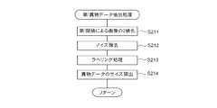
次にCPU53aは、ノイズ除去されたワーク撮像画像に対して第1異物データ抽出処理を実行する(ステップS206)。ここで、第1異物データ抽出処理について説明する。図11は、第1異物データ抽出処理の手順を示すフローチャートである。第1異物データ抽出処理では、まずCPU53aは、上述した異物検出初期化処理によって設定された第1閾値によるワーク撮像画像の2値化処理を実行する(ステップS211)。この2値化処理により、第1閾値よりも輝度の高い画素に異物を示す「1」の画素値が与えられ、第1閾値以下の輝度の画素には異物でないことを示す「0」の画素値が与えられる。
Next, the
次にCPU53aは、2値化画像に対して膨張・縮小処理によるノイズ除去を実行し(ステップS212)、ノイズ除去後の2値化画像に対してラベリング処理を実行することにより、画像に含まれる異物の像である異物データを抽出する(ステップS213)。さらにCPU53aは、抽出された異物データの画素数に1画素当たりの解像度を乗じることで、異物データのサイズを算出する(ステップS214)。
Next, the
ステップS214の処理の後、CPU53aは、第1異物データ抽出処理を終了し、メインルーチンにおける第1異物データ抽出処理の呼出アドレスへ処理を戻す。
After the process of step S214, the
次にCPU53aは、ステップS205においてノイズ除去されたワーク撮像画像に対して第2異物データ抽出処理を実行する(ステップS207)。ここで、第2異物データ抽出処理について説明する。図12は、第2異物データ抽出処理の手順を示すフローチャートである。第2異物データ抽出処理では、まずCPU53aは、上述した異物検出初期化処理によって設定された第2閾値によるワーク撮像画像の2値化処理を実行する(ステップS221)。この2値化処理により、第2閾値よりも輝度の低い画素に異物を示す「1」の画素値が与えられ、第2閾値以上の輝度の画素には異物でないことを示す「0」の画素値が与えられる。
Next, the
次にCPU53aは、2値化画像に対してノイズ除去(ステップS222)、ラベリング処理(ステップS223)、異物データのサイズ算出(ステップS224)を実行する。なお、ステップS222、S223、S224の処理のそれぞれは、上述したステップS212、S213、S214と同様であるので、その説明を省略する。
Next, the
ステップS224の処理の後、CPU53aは、第2異物データ抽出処理を終了し、メインルーチンにおける第2異物データ抽出処理の呼出アドレスへ処理を戻す。
After the process of step S224, the
上述した第1異物データ抽出処理によって高輝度の異物データが抽出され、第2異物データ抽出処理によって低輝度の異物データが抽出される。 High-intensity foreign matter data is extracted by the first foreign matter data extraction process described above, and low-intensity foreign matter data is extracted by the second foreign matter data extraction process.
次にCPU53aは、第1異物データ抽出処理及び第2異物データ抽出処理によって抽出された異物データのサイズを、予め与えられた基準値と比較して、当該基準値よりも大きいサイズの異物データが存在するか否かを判別する(ステップS208)。この結果、基準値よりも大きいサイズの異物データが存在する場合には(ステップS208においてYES)、CPU53aは、基準値よりも大きいサイズの異物データのワーク撮像画像上における位置情報をRAM53c又はハードディスク53dに記憶させ(ステップS209)、当該ワークのプレス加工の禁止を指示するプレス動作禁止指示信号をプレス制御装置4へ送信する(ステップS210)。プレス動作禁止指示信号がプレス制御装置4に与えられた場合には、プレス制御装置4はプレス加工装置2に当該ワークのプレス加工を実行させないように制御する。これにより、異物が付着したワークがプレス加工されることが防止され、オペレータはワークから異物を除去することができ、異物を除去した後にプレス加工装置2にプレス加工を実行させることができる。
Next, the
上述したステップS210の処理の後、CPU53aは、ステップS211へ処理を移す。他方、ステップS208において基準値よりも大きいサイズの異物データが存在しない場合には(ステップS208においてNO)、CPU53aは、そのままステップS211へ処理を移す。
After the process of step S210 described above, the
ステップS211において、CPU53aは、異物検出結果を示す異物検出結果画面を表示部54に表示させる(ステップS211)。ステップS211の処理の後、CPU53aは、異物検出処理を終了する。
In step S211, the
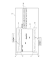
図13は、異物検出結果画面の一例を示す模式図である。異物検出結果画面D1には、ワーク撮像画像Wが含まれる。異物検出結果画面D1においては、搬送方向を右方向としてワーク撮像画像Wが表示される。また、異物検出画面D1において、ワーク撮像画像Wの上方には、第1カメラ61による撮像データの輝度値分布のグラフG1が表示され、ワーク撮像画像Wの下方には、第2カメラ62による撮像データの輝度値分布のグラフG2が表示される。グラフG1及びG2には、ワークの幅方向の特定の位置を撮像した画素における時系列の輝度値の変化が示される。ワーク撮像画像から異物が検出された場合には、この異物が検出された位置の画素が、前記特定の位置を撮像した画素とされ、ワークの先端から後端に至る当該画素の輝度値の変化がグラフG1及びグラフG2に示されることとなる。
FIG. 13 is a schematic diagram illustrating an example of a foreign object detection result screen. The foreign object detection result screen D1 includes a workpiece captured image W. In the foreign object detection result screen D1, the workpiece captured image W is displayed with the transport direction as the right direction. In the foreign object detection screen D1, a graph G1 of the luminance value distribution of the image data captured by the
また、グラフG1及びG2には、第1閾値を示す線分T1及び第2閾値を示す線分T2が重畳表示される。これにより、図13に示すように、輝度値のグラフG1及びG2のどの部分が第1閾値又は第2閾値を越え、これによって異物が検出されたかを、ユーザが容易に確認することができる。 In the graphs G1 and G2, a line segment T1 indicating the first threshold value and a line segment T2 indicating the second threshold value are superimposed and displayed. As a result, as shown in FIG. 13, the user can easily confirm which part of the luminance value graphs G1 and G2 has exceeded the first threshold value or the second threshold value, thereby detecting foreign matter.
さらに異物検出結果画面D1においては、ワーク撮像画像Wの右方に、検出された異物の位置情報及びサイズ情報を含む異物情報FMが示される。これにより、どの位置にどの程度のサイズの異物が検出されたかを、ユーザが容易に確認することができる。 Furthermore, in the foreign object detection result screen D1, the foreign object information FM including the position information and size information of the detected foreign object is shown on the right side of the workpiece captured image W. Thereby, the user can easily confirm how much foreign material is detected at which position.
<位置ずれ検出処理>
以上のような異物検出処理によってワークに異物が検出されなかった場合、プレス加工装置2にワークが供給された後、プレス加工が実行される前に、ワーク異常検出装置5による位置ずれ検出処理が実行される。
<Position detection processing>
When no foreign matter is detected in the workpiece by the foreign matter detection processing as described above, the position error detection processing by the workpiece
以下、位置ずれ検出処理について説明する。図14A及び図14Bは、位置ずれ検出処理の手順を示すフローチャートである。ワーク搬送装置3によってワークがプレス加工装置2に搬入されたときには、プレス制御装置4から搬送完了信号が画像処理ユニット52へ送信される。位置ずれ検出処理において、まずCPU53aは、プレス制御装置4から送信された搬送完了信号を受信したか否かを判別する(ステップS401)。ステップS401において、搬送完了信号が受信されていない場合には(ステップS401においてNO)、CPU53aは、搬送完了信号を受信するまで、ステップS401の処理を繰り返す。
Hereinafter, the misregistration detection process will be described. FIG. 14A and FIG. 14B are flowcharts showing the procedure of the positional deviation detection process. When the workpiece is carried into the
ステップS401において、搬送完了信号が受信された場合には(ステップS401においてYES)、CPU53aは、上述した位置ずれ検出初期化処理により決定された使用カメラに、金型の撮像を実行させる(ステップS402)。これにより、使用カメラから出力された画像データ(以下、「金型撮像画像」という。)が画像処理ユニット52により取得される。
In step S401, when a conveyance completion signal is received (YES in step S401), the
次にCPU53aは、金型撮像画像において位置決めピンの像が含まれる領域の部分画像を抽出する(ステップS403)。この部分画像は、金型情報に対応して設定された位置情報に従って金型撮像画像から抽出される。
Next, the
次にCPU53aは、抽出された部分画像と、対応する基準画像(位置ずれ検出初期化処理により設定された基準画像)とのパターンマッチングを実行する(ステップS404)。
Next, the
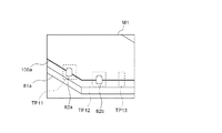
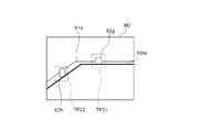
ここで、ステップS404のパターンマッチング処理について説明する。上述した位置ずれ検出初期化処理では、部分画像と同じ数の基準画像が設定される。つまり、部分画像と基準画像とは一対一に対応する。図15A及び図16Aは、基準画像の例を示す模式図である。基準画像は、予めオペレータがワークを金型上の正常な位置に載置した上で、使用カメラにより撮像することで得られた画像から抽出された部分画像である。図15Aに示す画像M1は、金型81aのカメラから見て手前側(つまり、前記搬送方向下流側)端部の左隅部を撮像したときに得られる画像である。また、図16Aに示す画像M2は、金型81aのカメラから見て奥側(つまり、前記搬送方向上流側)端部の左隅部を撮像したときに得られる画像である。図15Aに示す画像M1には、位置決めピン82a及び82bの像が含まれる。かかる画像M1からは、まず、位置決めピン82aの像を含む部分画像である基準画像TP11が取得される。
Here, the pattern matching process in step S404 will be described. In the positional deviation detection initialization process described above, the same number of reference images as the partial images are set. That is, the partial image and the reference image have a one-to-one correspondence. 15A and 16A are schematic diagrams illustrating examples of reference images. The reference image is a partial image extracted from an image obtained by an operator placing a work in a normal position on a mold in advance and taking an image with a camera in use. An image M1 illustrated in FIG. 15A is an image obtained when the left corner of the front end (that is, the downstream side in the transport direction) viewed from the camera of the
ステップS404のパターンマッチングでは、部分画像と基準画像とが比較される。例えば、図5に示すカメラ72によって得られる金型撮像画像から、位置決めピン82aの像を含む部分画像及び位置決めピン82bの像を含む部分画像が抽出される。位置決めピン82aの像を含む部分画像は、位置決めピン82aの像を含む基準画像と同じ撮像条件(照明、撮像方向、撮像倍率等)により撮像された画像である。このため、位置決めピン82aにワーク100aが乗り上げるような異常が生じていなければ、両者は非常に類似したものとなる。換言すれば、位置決めピン82aにワーク100aが乗り上げるような異常が生じていれば、位置決めピン82aの一部又は全部がワークで隠れた状態となり、両者の類似度は低下する。そこで、位置決めピン82aの像を含む部分画像と、位置決めピン82aの像を含む基準画像とのパターンマッチングが行われ、両画像の類似度が演算される。
In the pattern matching in step S404, the partial image and the reference image are compared. For example, a partial image including the image of the
CPU53aは、このようにして求められた類似度を所定の基準値と比較し、類似度が基準値以下である場合には(ステップS405においてYES)、当該部分画像に対応付けてエラー情報をRAM53c又はハードディスク53dに記憶し(ステップS406)、ステップS407へ処理を移す。他方、類似度が基準値より大きい場合には(ステップS405においてNO)、CPU53aは、そのままステップS407へ処理を移す。
The
ステップS407において、CPU53aは、全てのチェック対象の位置決めピンについて上述したステップS403〜S406の処理を実行したか否かを判定する(ステップS407)。まだ全てのチェック対象の位置決めピンについて処理が完了していない場合には(ステップS407においてNO)、CPU53aは、ステップS403へ処理を移し、次のチェック対象の位置決めピンについてステップS403〜S406の処理を実行する。これにより、例えば、上述した位置決めピン82aについて処理が行われた後には、金型撮像画像から位置決めピン82bの像を含む部分画像が抽出され、位置決めピン82bの像を含む部分画像と、位置決めピン82bの像を含む基準画像とのパターンマッチングが実行され、ワークの位置ずれ異常の検出が行われる。
In step S407, the
このようにして、図16Aに示す画像M2についても、位置決めピンの像を含む部分画像が抽出され、パターンマッチングが行われる。具体的には、画像M2には、位置決めピン82g及び82hの像が含まれる。かかる画像M2からは、位置決めピン82gの像を含む部分画像である基準画像TP21と、位置決めピン82hの像を含む部分画像である基準画像TP22とが取得され、それぞれの部分画像と、対応する基準画像とのパターンマッチングが実行され、ワークの位置ずれ異常の検出が行われる。
In this way, a partial image including the image of the positioning pin is also extracted from the image M2 shown in FIG. 16A, and pattern matching is performed. Specifically, the image M2 includes images of the positioning pins 82g and 82h. From this image M2, a reference image TP21 which is a partial image including the image of the
ステップS407において、全てのチェック対象の位置決めピンについて処理が完了した場合には(ステップS407においてYES)、CPU53aは、金型撮像画像においてワークのエッジ部の像が含まれる領域の部分画像を抽出する(ステップS408)。この部分画像は、金型情報に対応して設定された位置情報に従って金型撮像画像から抽出される。
In step S407, when the processing has been completed for all of the positioning pins to be checked (YES in step S407), the
次にCPU53aは、抽出された部分画像と、対応する基準画像とのパターンマッチングを実行する(ステップS409)。
Next, the
ここで、ステップS409のパターンマッチング処理について説明する。ステップS409のパターンマッチングでは、部分画像と基準画像とが比較される。例えば、図5に示すカメラ72によって得られる金型撮像画像から、ワーク100aのエッジ部の像を含む部分画像が抽出される。図15Aの例で説明すると、画像M1から、ワーク100aのエッジ部の像を含む部分画像である基準画像TP13が取得される。ワーク100aのエッジ部の像を含む部分画像は、サンプルワークのエッジ部の像を含む基準画像と同じ撮像条件により撮像された画像である。このため、ワーク100aが浮き上がったり、ずれたりするような異常が生じていなければ、両者は非常に類似したものとなる。換言すれば、ワーク100aが浮き上がったり、ずれたりするような異常が生じていれば、両者の類似度は低下する。そこで、ワーク100aのエッジ部の像を含む部分画像と、サンプルワークのエッジ部の像を含む基準画像とのパターンマッチングが行われ、両画像の類似度が演算される。
Here, the pattern matching process in step S409 will be described. In the pattern matching in step S409, the partial image and the reference image are compared. For example, a partial image including an image of the edge portion of the
CPU53aは、このようにして求められた類似度を所定の基準値と比較し、類似度が基準値以下である場合には(ステップS410においてYES)、当該部分画像に対応付けてエラー情報をRAM53c又はハードディスク53dに記憶し(ステップS411)、ステップS412へ処理を移す。他方、類似度が基準値より大きい場合には(ステップS410においてNO)、CPU53aは、そのままステップS412へ処理を移す。
The
ステップS412において、CPU53aは、全てのチェック対象のワークのエッジ部について上述したステップS408〜S411の処理を実行したか否かを判定する(ステップS412)。まだ全てのチェック対象のエッジ部について処理が完了していない場合には(ステップS412においてNO)、CPU53aは、ステップS408へ処理を移し、次のチェック対象の位置決めピンについてステップS408〜S411の処理を実行する。
In step S412, the
ステップS412において、全てのチェック対象のエッジ部について処理が完了した場合には(ステップS412においてYES)、CPU53aは、位置ずれ検出結果を示す位置ずれ検出結果画面を表示部54に表示させる(ステップS413)。
In step S412, when the processing has been completed for all the edge portions to be checked (YES in step S412), the
次に、CPU53aは、位置ずれ異常が発生したか否かを判別する(ステップS414)。ステップS414の処理では、RAM53c又はハードディスク53dにエラー情報が格納されているか否かを判別することにより、位置ずれ異常が発生したか否かが判別される。位置ずれ異常が発生している場合には(ステップS414においてYES)、CPU53aはプレス制御装置4へプレス動作停止指示信号を送信し(ステップS415)、位置ずれ検出処理を終了する。プレス制御装置4は、プレス動作停止指示信号を受信した場合、プレス加工動作を停止し、金型上に載置されているワークのプレス加工を実行しない。これにより、オペレータが位置ずれ検出結果画面によってワークの位置ずれの発生を確認し、停止しているプレス加工装置2内に配置されているワークを金型上の適切な位置に移動した上で、プレス加工の再開指示をプレス制御装置4に入力することができる。
Next, the
他方、位置ずれ異常が発生していない場合には(ステップS414においてNO)、CPU53aはプレス制御装置4へプレス動作許可信号を送信し(ステップS416)、位置ずれ検出処理を終了する。プレス制御装置4は、プレス動作許可信号を受信した場合、金型上に載置されているワークのプレス加工を実行する。これにより、金型上の正常な位置にワークが配置されている場合には、プレス加工動作が実行される。
On the other hand, if no misalignment has occurred (NO in step S414), the
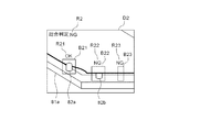
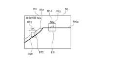
図15B及び図16Bは、位置ずれ検出結果画面の例を示す模式図である。図15B及び図16Bに示すように、位置ずれ検出結果画面D2,D3においては、使用カメラによる金型撮像画像が表示される。また、抽出された部分画像毎に、位置ずれ検出箇所を示す矩形枠B21,B22,B23,B31,B32が対応する部分画像を取り囲むように表示される。具体的には、図15Bに示す位置ずれ検出結果画面D2では、位置決めピン82aの像を含む部分画像に対応する枠B21と、位置決めピン82bの像を含む部分画像に対応する枠B22と、ワーク100aのエッジ部の像を含む部分画像に対応する枠B23とが表示される。また、図16Bに示す位置ずれ検出結果画面D3では、位置決めピン82gの像を含む部分画像に対応する枠B31と、位置決めピン82hの像を含む部分画像に対応する枠B32とが表示される。
FIG. 15B and FIG. 16B are schematic diagrams illustrating examples of the positional deviation detection result screen. As shown in FIG. 15B and FIG. 16B, on the misalignment detection result screens D2 and D3, the mold image captured by the camera used is displayed. In addition, for each extracted partial image, rectangular frames B21, B22, B23, B31, and B32 indicating the position detection positions are displayed so as to surround the corresponding partial images. Specifically, in the misalignment detection result screen D2 shown in FIG. 15B, the frame B21 corresponding to the partial image including the image of the
位置ずれ検出結果画面では、部分画像に対応する枠の近傍に、当該枠に対応して、当該枠によって示される部分画像における位置ずれ検出結果情報が表示される。位置ずれ検出処理の結果、ある部分画像について位置ずれ異常が発生していないと判断された場合には、その部分画像に対応する枠の近傍に位置ずれ検出結果情報として“OK”の文字列が表示される。また、位置ずれ検出処理の結果、他の部分画像について位置ずれ異常が発生していると判断された場合には、その部分画像に対応する枠の近傍に位置ずれ検出結果情報として“NG”の文字列が表示される。具体的に説明すると、図15Bに示す位置ずれ検出結果画面D2では、枠B21によって示される部分画像について位置ずれ異常が発生していないと判断された結果を示す位置ずれ検出結果情報R21として“OK”の文字列が、枠B21の上方に、枠B21と対応させて表示されている。また、位置ずれ検出結果画面D2では、枠B22によって示される部分画像について位置ずれ異常が発生していると判断された結果を示す位置ずれ検出結果情報R22として“NG”の文字列が、枠B22の上方に、枠B23と対応させて表示されており、枠B23によって示される部分画像について位置ずれ異常が発生していると判断された結果を示す位置ずれ検出結果情報R23として“NG”の文字列が、枠B23の上方に、枠B23と対応させて表示されている。同様に、図16Bに示す位置ずれ検出結果画面D3においても、枠B31と対応付けて、位置ずれ検出結果情報R31が表示され、枠B32と対応付けて、位置ずれ検出結果情報R32が表示されている。 On the misalignment detection result screen, misalignment detection result information on the partial image indicated by the frame is displayed in the vicinity of the frame corresponding to the partial image. As a result of the misalignment detection process, if it is determined that no misalignment has occurred in a partial image, a character string “OK” is displayed as misalignment detection result information in the vicinity of the frame corresponding to the partial image. Is displayed. As a result of the misregistration detection process, when it is determined that misregistration abnormality has occurred in another partial image, “NG” is detected as misregistration detection result information in the vicinity of the frame corresponding to the partial image. A character string is displayed. More specifically, in the misregistration detection result screen D2 shown in FIG. 15B, “OK” is provided as misregistration detection result information R21 indicating a result of determining that no misregistration abnormality has occurred in the partial image indicated by the frame B21. "Is displayed in correspondence with the frame B21 above the frame B21. In addition, in the misalignment detection result screen D2, the character string “NG” is displayed as the misalignment detection result information R22 indicating the result of determining that misalignment has occurred in the partial image indicated by the frame B22. Is displayed in correspondence with the frame B23, and the character “NG” is displayed as the position shift detection result information R23 indicating the result of determining that the position shift abnormality has occurred in the partial image indicated by the frame B23. A column is displayed above the frame B23 in association with the frame B23. Similarly, in the misalignment detection result screen D3 shown in FIG. 16B, misalignment detection result information R31 is displayed in association with the frame B31, and misalignment detection result information R32 is displayed in association with the frame B32. Yes.
さらに、位置ずれ検出結果画面では、その画面中に含まれる全ての部分画像についての位置ずれ検出処理の総合判定を示す総合判定情報が表示される。ここで、画面中に含まれる部分画像のうちの少なくとも1つについて位置ずれ異常が発生していると判断されている場合には、「位置ずれ異常が発生している」という総合判定がなされ、画面中に含まれる部分画像の全てにについて位置ずれ異常が発生していないと判断されている場合には、「位置ずれ異常が発生していない」という総合判定がなされる。例えば、図15Bに示す位置ずれ検出結果画面D2では、位置決めピン82bに対する位置ずれ検出結果、及び、ワーク100aのエッジ部に対する位置ずれ検出結果において、ワーク100aの位置ずれが検出されている。このため、当該位置ずれ検出結果画面D2では、総合判定として「位置ずれ異常が発生している」を示す総合判定情報R2として、“NG”の文字列が表示される。また、図16Bに示す位置ずれ検出結果画面D3では、位置決めピン82gに対する位置ずれ検出結果において、ワーク100aの位置ずれが検出されている。このため、当該位置ずれ検出結果画面D3では、総合判定として「位置ずれ異常が発生している」を示す総合判定情報R3として、“NG”の文字列が表示される。また、図には示していないが、総合判定結果が「位置ずれ異常が発生していない」である場合には、総合判定情報として“OK”が表示される。
Further, on the misregistration detection result screen, comprehensive judgment information indicating the overall judgment of misregistration detection processing for all partial images included in the screen is displayed. Here, when it is determined that a positional deviation abnormality has occurred for at least one of the partial images included in the screen, a comprehensive determination is made that "the positional deviation abnormality has occurred" When it is determined that no misregistration abnormality has occurred in all of the partial images included in the screen, a comprehensive determination is made that “no misregistration abnormality has occurred”. For example, in the positional deviation detection result screen D2 shown in FIG. 15B, the positional deviation of the
このような位置ずれ検出結果画面が表示されることにより、オペレータが、ワークの位置ずれが検出されたか否かを容易に確認することができる。また、ステップS413においては、全ての使用カメラによる位置ずれ検出結果画面(例えば、図5の例では、カメラ72,74,75,77による4つの位置ずれ検出結果画面)が表示部に並べて表示されるようになっている。これにより、どのカメラにより撮像されて得られた画像から、位置ずれが検出されたかをオペレータが容易に確認することができる。さらに、各位置ずれ検出結果画面においては、位置ずれ検出処理に用いられた部分画像毎に、部分画像と対応付けて位置ずれ検出結果情報が表示されるため、どの部分画像によって位置ずれが検出されたか、及び誤検出の有無をオペレータが容易に確認することができる。
By displaying such a displacement detection result screen, the operator can easily confirm whether or not the displacement of the workpiece has been detected. In step S413, misalignment detection result screens for all the cameras used (for example, in the example of FIG. 5, four misalignment detection result screens for the
上述の如く、本実施の形態に係るワーク異常検出装置5は、金型の位置決めピンを撮像して得られた画像から、ワークの位置ずれを検出する構成であるため、位置ずれ検出の結果がワークの材質、色、形等により影響を受けることを従来に比して抑制することができる。
As described above, since the workpiece
また、本実施の形態に係るワーク異常検出装置5は、金型の位置決めピンの少なくとも一部がワークに隠れているか否かを画像処理によって判別し、この判別結果により位置ずれ検出を行う構成であるため、画像中の位置決めピンの像の形態が正常(ワークに隠れていないときの形態)と異なるか否かを判別するという簡便な処理により、ワークの位置ずれの検出を行うことができる。
Further, the workpiece
また、本実施の形態に係るワーク異常検出装置5は、金型上の正常な位置にワークが配置されているときの基準画像と、撮像して得られた画像とのパターンマッチングにより、位置ずれの検出を行う構成であるため、画像中の位置決めピンの像の形態が正常な形態(ワークに隠れていないときの形態)と異なるか否かを簡便な処理で判別することが可能となる。
In addition, the workpiece
また、本実施の形態に係るワーク異常検出装置5は、上記の位置決めピンの形態によるワークの位置ずれ検出に加え、ワークの端縁が所定位置にあるか否かを画像処理により判別することで、ワークの位置ずれを検出する構成であるため、位置決めピンの形態に係る画像処理では捕捉できないワークの位置ずれを、ワークの端縁に係る画像処理により検出することができ、より一層検出精度を高めることができる。
Further, the workpiece
また、本実施の形態に係るワーク異常検出装置5は、金型上の正常な位置にワークが配置されているときの基準画像と、撮像して得られた画像とのパターンマッチングにより、位置ずれの検出を行う構成であるため、画像中のワークの端縁の位置が正常な位置(ワークが浮き上がったり、ずれたりしていないときの位置)と異なるか否かを簡便な処理で判別することが可能となる。
In addition, the workpiece
また、本実施の形態に係るワーク異常検出装置5にあっては、プレス加工装置2に装着されている金型の種類を特定する金型情報を受け付け、この金型情報に基づいて、カメラ71〜78のうち、金型に対応するカメラを、画像処理に使用するカメラとして選択的に決定する構成であるため、金型の種類に応じて、適切なカメラを使用カメラとして決定することができ、また、複数種類の金型に適切に対応してワークの位置ずれ検出を行うことが可能である。
Moreover, in the workpiece | work
また、本実施の形態に係るワーク異常検出装置5にあっては、プレス加工装置2におけるワークの位置ずれ検出に加え、搬送されているワークに付着した異物の検出を行う構成であるため、ワークの搬送からプレス加工に至る工程の途中で、従来オペレータが目視により行っていたワークの位置ずれ及び異物検出が自動的に行われる。したがって、ワークの搬送からプレス加工に至るプレス加工システムの一連の動作を自動で行うことが可能となる。
In addition, the workpiece
(その他の実施の形態)
なお、上述した実施の形態においては、1台のカメラによって複数の位置決めピンを撮像し、これによって得られた画像から位置決めピンの像を含む部分画像を抽出して、部分画像毎に画像処理を行う構成について述べたが、これに限定されるものではない。1台のカメラで1つの位置決めピンを撮像し、その画像を基準画像と比較することでワークの位置ずれ検出を行う構成であってもよい。また、1台のカメラで複数の位置決めピンを撮像し、これによって得られた画像をそのまま基準画像と比較して、ワークの位置ずれ検出を行う構成であってもよい。
(Other embodiments)
In the above-described embodiment, a plurality of positioning pins are imaged by one camera, a partial image including the positioning pin image is extracted from the image obtained by this, and image processing is performed for each partial image. Although the configuration to be performed has been described, the present invention is not limited to this. The configuration may be such that one positioning pin is imaged by one camera, and the position deviation of the workpiece is detected by comparing the image with a reference image. Alternatively, a configuration may be adopted in which a plurality of positioning pins are picked up by a single camera, and an image obtained thereby is directly compared with a reference image to detect a workpiece displacement.
また、上述した実施の形態においては、金型に設けられた位置決めピンをカメラ71〜78により撮像し、これによって得られた画像に基づいてワークの位置ずれを検出する校正について述べたが、これに限定されるものではない。撮像対象は位置決めピンに限られず、金型に設けられた凸状の部分で、ワークと当接することでワークを位置決めするための位置決め部であれば、どのようなものでもよい。例えば、下型の上面から突出した直方体形状の位置決め部であってもよい。
Further, in the above-described embodiment, the calibration is described in which the positioning pins provided on the mold are imaged by the
また、上述した実施の形態においては、ワークの端縁部の部分画像を基準画像と比較することで、ワークの位置ずれを検出する構成としたが、これに限定されるものではない。位置決めピンの形態の異常をパターンマッチングで検出することで、ワークの位置ずれ検出を行う機能のみを有し、ワークの端縁部の画像のパターンマッチングによるワークの位置ずれ検出の機能を有しない構成とすることもできる。 In the above-described embodiment, the configuration is such that the positional deviation of the workpiece is detected by comparing the partial image of the edge portion of the workpiece with the reference image. However, the present invention is not limited to this. A configuration that has only the function to detect the positional deviation of the workpiece by detecting an abnormality in the form of the positioning pin by pattern matching, and does not have the function to detect the positional deviation of the workpiece by pattern matching of the image of the edge of the workpiece. It can also be.
また、上述した実施の形態においては、位置決めピンの画像をパターンマッチングにより基準画像と比較することで、位置決めピンの形態の異常を検出し、これによってワークの位置ずれの検出を行う構成について述べたが、これに限定されるものではない。例えば、位置決めピンの画像から位置決めピンの形態を画像処理により認識し、認識された位置決めピンの形態が正常か否かを判断することにより、ワークの位置ずれを検出する構成としてもよい。 Further, in the above-described embodiment, the configuration in which the positioning pin image is compared with the reference image by pattern matching to detect an abnormality in the positioning pin configuration and thereby detect the positional deviation of the workpiece is described. However, the present invention is not limited to this. For example, the configuration of the positioning pin may be detected by recognizing the configuration of the positioning pin from the positioning pin image by image processing and determining whether or not the recognized positioning pin configuration is normal.
また、上述した実施の形態においては、金型の種類に応じてワークの位置ずれ検出に使用するカメラを切り替える構成について述べたが、これに限定されるものではない。複数種類の金型に対して同一のカメラにより撮像を行い、得られた画像に基づいてワークの位置ずれ検出を行う構成としてもよい。 In the above-described embodiment, the configuration is described in which the camera used for detecting the positional deviation of the workpiece is switched according to the type of the mold, but the present invention is not limited to this. It is good also as a structure which image-captures with respect to several types of metal mold | die with the same camera, and detects the position shift of a workpiece | work based on the obtained image.
また、上述した実施の形態においては、複数の位置ずれ検出結果画面を並べて表示部54に表示する構成について述べたが、これに限定されるものではない。1度に1つの位置ずれ検出結果画面を表示し、各位置ずれ検出結果画面の表示を時刻で切り替えもよい。
In the above-described embodiment, the configuration in which a plurality of misalignment detection result screens are displayed side by side on the
また、上述した実施の形態においては、画像処理に用いられた部分画像を取り囲むように矩形の枠を表示し、当該枠により部分画像(位置決めピン又はエッジ部の像)を指示する構成について述べたが、これに限定されるものではない。矩形枠以外の図形により部分画像を指示する構成としてもよい。例えば、位置決めピン又はエッジ部の像の近傍に矢印を表示し、この矢印によって前記位置決めピン又はエッジ部の像を指示するようにしてもよい。また、位置決めピン又はエッジ部の像を取り囲むように円形の枠、又は四角形以外の多角形の枠を表示することにより、前記位置決めピン又はエッジ部の像を指示するようにしてもよい。 In the embodiment described above, a configuration has been described in which a rectangular frame is displayed so as to surround the partial image used for image processing, and the partial image (positioning pin or image of the edge portion) is indicated by the frame. However, the present invention is not limited to this. A configuration may be adopted in which a partial image is indicated by a figure other than a rectangular frame. For example, an arrow may be displayed near the image of the positioning pin or the edge portion, and the image of the positioning pin or the edge portion may be indicated by this arrow. Further, the positioning pin or the image of the edge portion may be indicated by displaying a circular frame or a polygonal frame other than the quadrangle so as to surround the positioning pin or the image of the edge portion.
また、上述した実施の形態においては、位置ずれ検出結果画面において、画像処理に用いられた部分画像毎に、位置ずれ検出結果情報を表示する構成としたが、これに限定されるものではない。総合判定情報を表示し、部分画像毎の位置ずれ検出結果情報を表示しない構成としてもよい。 In the above-described embodiment, the positional deviation detection result screen is configured to display the positional deviation detection result information for each partial image used for image processing. However, the present invention is not limited to this. It is good also as a structure which displays comprehensive determination information and does not display the position shift detection result information for every partial image.
また、上述した実施の形態においては、カメラ71〜78の撮像範囲を照明する光源として、ハロゲンライト79を使用する構成について述べたが、これに限定されるものではない。光源として使用可能なものであればその種類は特に限定されず、例えば蛍光灯であってもよいし、LED照明であってもよい。
In the above-described embodiment, the configuration in which the
また、上述した実施の形態においては、単一のコンピュータ52aによりコンピュータプログラム56aの全ての処理を実行する構成について述べたが、これに限定されるものではなく、上述したコンピュータプログラム56aと同様の処理を、複数の装置(コンピュータ)により分散して実行する分散システムとすることも可能である。
In the above-described embodiment, the configuration in which all processing of the
本発明のワークの位置ずれ検出装置、ワークの位置ずれ検出方法、及びコンピュータプログラムは、金属板プレス加工の対象物であるワークの金型に対する位置ずれを検出するためのワークの位置ずれ検出装置、ワークの位置ずれ検出方法、及びコンピュータにワークの金型に対する位置ずれを検出させるためのコンピュータプログラムとして有用である。 Workpiece misalignment detection apparatus, work misalignment detection method, and computer program according to the present invention are a work misalignment detection apparatus for detecting misalignment of a work that is an object of metal plate press processing with respect to a mold, The present invention is useful as a method for detecting a displacement of a workpiece and a computer program for causing a computer to detect a displacement of a workpiece with respect to a mold.
1 プレス加工システム
2 プレス加工装置
3 ワーク搬送装置
31 ワーク搬送台
4 プレス制御装置
5 ワーク異常検出装置
51 撮像ユニット
52 画像処理ユニット
52a コンピュータ
54 表示部
55 入力部
53a CPU
53c RAM
53d ハードディスク
53k 画像生成回路
56 可搬型記録媒体
56a コンピュータプログラム
61 第1カメラ
62 第2カメラ
63 照明ユニット
65 第1光学式センサ
66 第2光学式センサ
71〜78 カメラ
71a〜78a 撮像領域
79 ハロゲンライト
81,81a,81b 金型
82a〜82h 位置決めピン
83a〜83h 位置決めピン
100,100a,100b ワーク
DESCRIPTION OF
53c RAM
53d
Claims (11)
前記金型上にワークが設置されている場合に前記撮像部が前記位置決め部を撮像することにより得られた画像に基づいて、前記金型上におけるワークの位置ずれを検出する画像処理部と、
を備える、
ワークの位置ずれ検出装置。 When a workpiece is installed on a mold installed in the press working apparatus, the positioning portion provided in the mold is arranged at a position where the workpiece can be imaged in order to position the workpiece by contacting the workpiece. An imaging unit,
An image processing unit that detects a positional deviation of the workpiece on the mold based on an image obtained by the imaging unit imaging the positioning unit when a workpiece is installed on the mold; and
Comprising
Work position deviation detection device.
請求項1に記載のワークの位置ずれ検出装置。 The image processing unit is configured to detect a positional deviation of the workpiece on the mold by determining whether or not at least a part of the positioning unit is hidden in the workpiece in the image.
The work position detection apparatus according to claim 1.
請求項2に記載のワークの位置ずれ検出装置。 The image processing unit compares the reference image, which is an image of the positioning unit when a workpiece is normally placed on the mold, with an image obtained by the imaging unit, thereby comparing the image in the image. It is configured to determine whether or not at least a part of the positioning part is hidden behind the workpiece,
The workpiece displacement detection device according to claim 2.
前記画像処理部は、前記撮像部により得られた画像において前記ワークの端縁が所定位置にあるか否かを判別することにより、前記金型上におけるワークの位置ずれを検出するように構成されている、
請求項2又は3に記載のワークの位置ずれ検出装置。 The imaging unit is configured to perform imaging in an imaging range including an edge of a workpiece installed on the mold,
The image processing unit is configured to detect a positional deviation of the workpiece on the mold by determining whether or not an edge of the workpiece is in a predetermined position in the image obtained by the imaging unit. ing,
The workpiece displacement detection device according to claim 2 or 3.
請求項4に記載のワークの位置ずれ検出装置。 The image processing unit compares the reference image, which is an image of the positioning unit when a workpiece is normally placed on the mold, with an image obtained by the imaging unit, thereby comparing the image in the image. Configured to determine whether the edge of the workpiece is in a predetermined position,
The workpiece displacement detection device according to claim 4.
入力部をさらに備え、
前記画像処理部は、第1の金型の使用を示す第1金型情報が前記入力部に与えられたときは、前記第1撮像部により得られた画像に基づいて、前記第1の金型上におけるワークの位置ずれを検出し、前記第1の金型とは異なる第2の金型の使用を示す第2金型情報が前記入力部に与えられたときは、前記第2撮像部により得られた画像に基づいて、前記第2の金型上におけるワークの位置ずれを検出するように構成されている、
請求項1乃至5の何れかに記載のワークの位置ずれ検出装置。 The imaging unit includes a first imaging unit and a second imaging unit having different imaging ranges,
An input unit,
When the first mold information indicating the use of the first mold is given to the input unit, the image processing unit is configured to use the first mold based on an image obtained by the first imaging unit. When the second mold information indicating the use of a second mold different from the first mold is given to the input unit, the second image pickup unit is detected. Based on the image obtained by the above, it is configured to detect a positional deviation of the workpiece on the second mold,
The work position deviation detecting device according to claim 1.
請求項1乃至6の何れかに記載のワークの位置ずれ検出装置。 A display unit for displaying a misregistration detection result screen including an image obtained by the imaging unit and information indicating a determination result as to whether or not at least a part of the positioning unit is hidden by a workpiece;
The work position deviation detection device according to claim 1.
請求項7に記載のワークの位置ずれ検出装置。 The display unit displays, on the misalignment detection result screen, a graphic indicating the image of the positioning unit that has performed the determination as to whether or not the workpiece is hidden on the image obtained by the imaging unit, It is configured to display information indicating a determination result of whether or not at least a part of the positioning unit indicated by the graphic is hidden in the workpiece,
The workpiece position detection apparatus according to claim 7.
前記ラインスキャンカメラによって得られたワークの画像に対して二値化処理を実行し、前記二値化処理により得られた二値化画像に基づいて前記ワーク上の異物を検出する第2画像処理部と、
をさらに備える、
請求項1乃至8の何れかに記載のワークの位置ずれ検出装置。 A line scan camera that images the workpiece being conveyed in the conveyance path for conveying the workpiece to the press working device;
Second image processing for executing a binarization process on an image of a work obtained by the line scan camera and detecting foreign matter on the work based on the binarized image obtained by the binarization process And
Further comprising
The work position deviation detection device according to claim 1.
撮像により得られた画像に基づいて、前記金型上におけるワークの位置ずれを検出するステップと、
を有する、
ワークの位置ずれ検出方法。 When the workpiece is normally installed on the mold installed in the press working apparatus, the positioning portion provided on the mold is positioned at a position where the workpiece can be imaged in order to position the workpiece by contacting the workpiece. Imaging the positioning unit at a time when a workpiece is placed on the mold by the arranged imaging unit;
Detecting a positional deviation of a workpiece on the mold based on an image obtained by imaging;
Having
A method for detecting the displacement of a workpiece
前記金型上にワークが正常に設置されているときに、ワークと当接することによりワークを位置決めするために前記金型に設けられた位置決め部を撮像可能な位置から、前記金型上にワークが設置されている時点で前記位置決め部を撮像することにより得られた画像を取得するステップと、
取得された画像に基づいて、前記金型上におけるワークの位置ずれを検出するステップと、
を前記コンピュータに実行させる、
コンピュータプログラム。 A computer program for causing a computer to detect a positional deviation of a workpiece with respect to a mold installed in a press working apparatus,
When a workpiece is normally installed on the mold, the workpiece is placed on the mold from a position where the positioning portion provided on the mold can be imaged in order to position the workpiece by contacting the workpiece. Acquiring an image obtained by imaging the positioning unit at the time when is installed;
Detecting a position shift of the workpiece on the mold based on the acquired image;
Causing the computer to execute
Computer program.
Priority Applications (1)
| Application Number | Priority Date | Filing Date | Title |
|---|---|---|---|
| JP2012056277A JP5932413B2 (en) | 2012-03-13 | 2012-03-13 | Work position displacement detection device, work position displacement detection method, and computer program |
Applications Claiming Priority (1)
| Application Number | Priority Date | Filing Date | Title |
|---|---|---|---|
| JP2012056277A JP5932413B2 (en) | 2012-03-13 | 2012-03-13 | Work position displacement detection device, work position displacement detection method, and computer program |
Publications (2)
| Publication Number | Publication Date |
|---|---|
| JP2013188773A true JP2013188773A (en) | 2013-09-26 |
| JP5932413B2 JP5932413B2 (en) | 2016-06-08 |
Family
ID=49389597
Family Applications (1)
| Application Number | Title | Priority Date | Filing Date |
|---|---|---|---|
| JP2012056277A Active JP5932413B2 (en) | 2012-03-13 | 2012-03-13 | Work position displacement detection device, work position displacement detection method, and computer program |
Country Status (1)
| Country | Link |
|---|---|
| JP (1) | JP5932413B2 (en) |
Cited By (5)
| Publication number | Priority date | Publication date | Assignee | Title |
|---|---|---|---|---|
| JP2016007689A (en) * | 2014-06-26 | 2016-01-18 | 株式会社ディスコ | Wire-saw device |
| KR20160089979A (en) * | 2015-01-21 | 2016-07-29 | 주식회사 에코노미아 | Hot press forming device and method for discriminating position of metal plate using the same |
| CN113658090A (en) * | 2020-04-29 | 2021-11-16 | 河北荣泰模具科技股份有限公司 | Intelligent detection and discrimination method for metal die parts |
| CN115112853A (en) * | 2021-03-22 | 2022-09-27 | 上海申光高强度螺栓有限公司 | Online quality detection method for bolt red punching machining process |
| CN120396427A (en) * | 2025-06-30 | 2025-08-01 | 浙江萧山金龟机械有限公司 | A press intelligent control method |
Citations (6)
| Publication number | Priority date | Publication date | Assignee | Title |
|---|---|---|---|---|
| JPH03230824A (en) * | 1990-02-06 | 1991-10-14 | Citizen Watch Co Ltd | Method for working strip |
| JPH0491830A (en) * | 1990-08-03 | 1992-03-25 | Amada Metrecs Co Ltd | Work origin setter of plate treating device |
| JPH0599858A (en) * | 1991-10-09 | 1993-04-23 | Kawasaki Steel Corp | Attachment detection method |
| JP2002035871A (en) * | 2000-07-31 | 2002-02-05 | Satomi Sangyo Kk | Heat transfer part formation method |
| JP2004017072A (en) * | 2002-06-13 | 2004-01-22 | Amada Co Ltd | Bending machine |
| JP2009106972A (en) * | 2007-10-30 | 2009-05-21 | Amada Co Ltd | Bending machine |
-
2012
- 2012-03-13 JP JP2012056277A patent/JP5932413B2/en active Active
Patent Citations (6)
| Publication number | Priority date | Publication date | Assignee | Title |
|---|---|---|---|---|
| JPH03230824A (en) * | 1990-02-06 | 1991-10-14 | Citizen Watch Co Ltd | Method for working strip |
| JPH0491830A (en) * | 1990-08-03 | 1992-03-25 | Amada Metrecs Co Ltd | Work origin setter of plate treating device |
| JPH0599858A (en) * | 1991-10-09 | 1993-04-23 | Kawasaki Steel Corp | Attachment detection method |
| JP2002035871A (en) * | 2000-07-31 | 2002-02-05 | Satomi Sangyo Kk | Heat transfer part formation method |
| JP2004017072A (en) * | 2002-06-13 | 2004-01-22 | Amada Co Ltd | Bending machine |
| JP2009106972A (en) * | 2007-10-30 | 2009-05-21 | Amada Co Ltd | Bending machine |
Cited By (7)
| Publication number | Priority date | Publication date | Assignee | Title |
|---|---|---|---|---|
| JP2016007689A (en) * | 2014-06-26 | 2016-01-18 | 株式会社ディスコ | Wire-saw device |
| KR20160089979A (en) * | 2015-01-21 | 2016-07-29 | 주식회사 에코노미아 | Hot press forming device and method for discriminating position of metal plate using the same |
| KR101675478B1 (en) * | 2015-01-21 | 2016-11-11 | 주식회사 에코노미아 | Hot press forming device and method for discriminating position of metal plate using the same |
| CN113658090A (en) * | 2020-04-29 | 2021-11-16 | 河北荣泰模具科技股份有限公司 | Intelligent detection and discrimination method for metal die parts |
| CN113658090B (en) * | 2020-04-29 | 2024-11-08 | 河北荣泰模具科技股份有限公司 | Intelligent detection and identification method for metal mold parts |
| CN115112853A (en) * | 2021-03-22 | 2022-09-27 | 上海申光高强度螺栓有限公司 | Online quality detection method for bolt red punching machining process |
| CN120396427A (en) * | 2025-06-30 | 2025-08-01 | 浙江萧山金龟机械有限公司 | A press intelligent control method |
Also Published As
| Publication number | Publication date |
|---|---|
| JP5932413B2 (en) | 2016-06-08 |
Similar Documents
| Publication | Publication Date | Title |
|---|---|---|
| JP6619194B2 (en) | Touch panel inspection apparatus and method | |
| JP5932413B2 (en) | Work position displacement detection device, work position displacement detection method, and computer program | |
| US8610770B2 (en) | Image sensing apparatus and method for sensing target that has defective portion region | |
| US20170053394A1 (en) | Inspection apparatus, inspection method, and article manufacturing method | |
| JP2022507678A (en) | Optimization of setup stage in automated visual inspection process | |
| CN116997927B (en) | Method and System for Detecting Bubbles on Curved Substrates | |
| CN106846294B (en) | Visual detection method, device and equipment | |
| CN104237246A (en) | Defect identification method of optical thin film | |
| JPH04238592A (en) | Automatic bundled bar steel tally device | |
| KR20170011791A (en) | An apparatus for detecting optical defects of tempered glass and ito pattern defects in touch screen panel and the method thereof | |
| CN110646432A (en) | Glass crack inspection system and method | |
| JP2003216928A (en) | Normal/defective confection deciding system | |
| JP6792283B2 (en) | Visual inspection equipment | |
| JP2002365227A (en) | Press inspection equipment | |
| WO2010109856A1 (en) | Device and method for inspecting display panel lighting | |
| JP2007155405A (en) | Appearance inspection method and appearance inspection apparatus | |
| JP7300155B2 (en) | Teaching device in solid preparation appearance inspection, and teaching method in solid preparation appearance inspection | |
| JP6180889B2 (en) | Printing inspection device | |
| JP5778685B2 (en) | System and method for alignment and inspection of ball grid array devices | |
| JP2006189293A (en) | Inspection method and apparatus for streaky unevenness defect | |
| JP4135367B2 (en) | Defect detection method | |
| JPH09314071A (en) | Visual inspection support system | |
| JP2002257749A (en) | Inspection apparatus, inspection method and color filter manufacturing method using the same | |
| JPH03156349A (en) | Foreign-matter detecting method | |
| JP2020030057A (en) | Inspection device of electronic component and inspection method of electronic component |
Legal Events
| Date | Code | Title | Description |
|---|---|---|---|
| A621 | Written request for application examination |
Free format text: JAPANESE INTERMEDIATE CODE: A621 Effective date: 20150127 |
|
| A977 | Report on retrieval |
Free format text: JAPANESE INTERMEDIATE CODE: A971007 Effective date: 20160107 |
|
| A131 | Notification of reasons for refusal |
Free format text: JAPANESE INTERMEDIATE CODE: A131 Effective date: 20160112 |
|
| A521 | Request for written amendment filed |
Free format text: JAPANESE INTERMEDIATE CODE: A523 Effective date: 20160202 |
|
| TRDD | Decision of grant or rejection written | ||
| A01 | Written decision to grant a patent or to grant a registration (utility model) |
Free format text: JAPANESE INTERMEDIATE CODE: A01 Effective date: 20160426 |
|
| A61 | First payment of annual fees (during grant procedure) |
Free format text: JAPANESE INTERMEDIATE CODE: A61 Effective date: 20160428 |
|
| R150 | Certificate of patent or registration of utility model |
Ref document number: 5932413 Country of ref document: JP Free format text: JAPANESE INTERMEDIATE CODE: R150 |
|
| R250 | Receipt of annual fees |
Free format text: JAPANESE INTERMEDIATE CODE: R250 |
|
| R250 | Receipt of annual fees |
Free format text: JAPANESE INTERMEDIATE CODE: R250 |
|
| R250 | Receipt of annual fees |
Free format text: JAPANESE INTERMEDIATE CODE: R250 |
|
| S533 | Written request for registration of change of name |
Free format text: JAPANESE INTERMEDIATE CODE: R313533 |
|
| R350 | Written notification of registration of transfer |
Free format text: JAPANESE INTERMEDIATE CODE: R350 |
|
| R250 | Receipt of annual fees |
Free format text: JAPANESE INTERMEDIATE CODE: R250 |
|
| R250 | Receipt of annual fees |
Free format text: JAPANESE INTERMEDIATE CODE: R250 |
|
| R250 | Receipt of annual fees |
Free format text: JAPANESE INTERMEDIATE CODE: R250 |
|
| R250 | Receipt of annual fees |
Free format text: JAPANESE INTERMEDIATE CODE: R250 |