JP2013190859A - Drain structure for electrical equipment - Google Patents
Drain structure for electrical equipment Download PDFInfo
- Publication number
- JP2013190859A JP2013190859A JP2012054876A JP2012054876A JP2013190859A JP 2013190859 A JP2013190859 A JP 2013190859A JP 2012054876 A JP2012054876 A JP 2012054876A JP 2012054876 A JP2012054876 A JP 2012054876A JP 2013190859 A JP2013190859 A JP 2013190859A
- Authority
- JP
- Japan
- Prior art keywords
- housing
- drainage
- water
- sealing body
- gas
- Prior art date
- Legal status (The legal status is an assumption and is not a legal conclusion. Google has not performed a legal analysis and makes no representation as to the accuracy of the status listed.)
- Granted
Links
Images


Landscapes
- Fire-Detection Mechanisms (AREA)
- Emergency Alarm Devices (AREA)
- Fire Alarms (AREA)
Abstract
【課題】筺体の内部に水が浸入したとしても、筺体の内部に配設してある部材に水が触れ難く、かつ、浸入した水を筺体の外部に排出し易い電気機器の水抜き構造を提供する。
【解決手段】機器本体および機器本体の少なくとも一部を覆う封止体20を有する筺体Yと、筺体Yの内部に設けられ、外部環境の変化を検知する検知部を配設した基板部と、封止体20から筺体Yの内部の側に向って立設し、検知部を収容する収容部22と、を備え、収容部22に浸入した水を排出する収容部排水路22aを封止体20に沿って形成した電気機器の水抜き構造。
【選択図】図5A water drainage structure for an electrical device that makes it difficult for water to come into contact with members arranged inside the housing even when water enters the housing and to easily drain the infiltrated water to the outside of the housing. provide.
A housing Y having a sealing body 20 covering at least a part of the device main body and the device main body, a substrate portion provided inside the housing Y and provided with a detection unit for detecting a change in the external environment, A housing portion 22 that is erected from the sealing body 20 toward the inside of the housing Y and that houses the detection portion, and the housing portion drainage path 22a that discharges water that has entered the housing portion 22 is sealed. A drainage structure for electrical equipment formed along the line 20.
[Selection] Figure 5
Description
本発明は、屋内や屋外で壁面に設置される防災用又は防犯用の電気機器において、当該電気機器の内部空間に浸入した水を電気機器の外部に排出する水抜き構造に関する。 The present invention relates to a drainage structure for discharging water that has entered an internal space of an electrical device, which is installed on a wall surface indoors or outdoors, to the outside of the electrical device.
例えば浴室内で使用する電子機器として、特許文献1には、スピーカを収容する筐体を備えたガス警報器が開示されている。当該筺体には、当該筐体を貫通する放音孔と、前記放音孔を囲むように筐体内部に向かって立設すると共にその開口が前記スピーカで塞がれた放音筒部と、が設けられており、当該放音筒部には、その内周面に鉛直下側に向かって凹の水溜り部が設けてある。 For example, as an electronic device used in a bathroom, Patent Literature 1 discloses a gas alarm device including a housing that houses a speaker. In the housing, a sound emitting hole penetrating the housing, a sound emitting tube portion standing up toward the inside of the housing so as to surround the sound emitting hole, and an opening of which is closed by the speaker, The sound emitting tube portion is provided with a recessed water pool portion on the inner peripheral surface thereof in a vertically downward direction.
このように警報器を構成することで、放音筒部の内周面に鉛直下側に向かって凹の水溜り部を設けることにより、放音孔から放音筒部内に水が侵入しても水溜り部に水が溜まるためスピーカの振動板に水が付着することがない。これにより、スピーカの振動板の発音不良を防止すると共にスピーカの劣化を防ぐことができる。 By configuring the alarm device in this way, by providing a concave water pool portion on the inner peripheral surface of the sound emitting tube portion vertically downward, water enters the sound emitting tube portion from the sound emitting hole. In addition, since water accumulates in the water reservoir, water does not adhere to the diaphragm of the speaker. As a result, it is possible to prevent poor sound generation of the speaker diaphragm and to prevent deterioration of the speaker.
また、特許文献1に記載の警報器には、一端が水溜り部に連通し他端が鉛直下側に開口し、筐体外面に凹に設けられた水抜き溝が設けてある。これにより、水溜り部に溜まった水が水抜き溝を通って筐体外部に排出される。このため、より確実に、スピーカの振動板の発音不良を防止すると共にスピーカの劣化を防ぐことができる。 In addition, the alarm device described in Patent Document 1 has a drainage groove provided at one end thereof in communication with the water reservoir, the other end opened vertically downward, and a recess provided on the outer surface of the housing. Thereby, the water collected in the water reservoir is discharged to the outside of the housing through the drain groove. For this reason, it is possible to more reliably prevent the sound generation failure of the speaker diaphragm and the deterioration of the speaker.
特許文献1に記載の警報器は、例えば浴室内で使用するものであるが、被検知ガスを筺体の内部に導入するガス導入口から水が浸入する虞がある。仮にガス導入口から水が筺体の内部に浸入すれば、当該内部に配設してあるガス検知素子や基板などの部材に水が触れたりして、これら部材が故障する虞があった。 The alarm device described in Patent Document 1 is used in, for example, a bathroom, but there is a possibility that water may enter from a gas introduction port that introduces a gas to be detected into the housing. If water enters the interior of the housing from the gas inlet, water may touch members such as the gas detection element and the substrate disposed inside the housing, which may cause failure of these members.
従って、本発明の目的は、筺体の内部に水が浸入したとしても、筺体の内部に配設してある部材に水が触れ難く、かつ、浸入した水を筺体の外部に排出し易い電気機器の水抜き構造を提供することにある。 Accordingly, an object of the present invention is to provide an electrical device in which even if water enters the inside of the housing, it is difficult for the water to touch the members disposed inside the housing, and the intruded water is easily discharged to the outside of the housing. It is to provide a water draining structure.
上記目的を達成するための本発明に係る電気機器の水抜き構造の第一特徴構成は、機器本体および当該機器本体の少なくとも一部を覆う封止体を有する筺体と、前記筺体の内部に設けられ、外部環境の変化を検知する検知部を配設した基板部と、前記封止体から前記筺体の内部の側に向って立設し、前記検知部を収容する収容部と、を備え、前記収容部に浸入した水を排出する収容部排水路を前記封止体に沿って形成した点にある。 In order to achieve the above object, the first characteristic configuration of the drainage structure for an electric device according to the present invention is a housing having a device body and a sealing body covering at least a part of the device body, and provided inside the housing. A substrate portion provided with a detection portion for detecting a change in the external environment, and a storage portion that is erected from the sealing body toward the inside of the housing and stores the detection portion, In the point which formed the accommodating part drainage channel which discharges the water which permeated the said accommodating part along the said sealing body.
本構成のように収容部に検知部を収容することで、収容された検知部を筺体の内部空間から隔離することができる。よって、仮に筺体の内部に水が浸入したとしても、筺体の内部空間から隔離してある検知部に水が触れ難くなるため、検知部が水に触れることによる破損や劣化を未然に防止できる。
また、本構成のように、収容部に浸入した水を排出する収容部排水路が封止体に沿って形成してあれば、収容部に浸入した水を直ちに収容部排水路によって排出することができる。
By storing the detection unit in the storage unit as in this configuration, the stored detection unit can be isolated from the internal space of the housing. Therefore, even if water enters the inside of the housing, it is difficult for water to touch the detection unit isolated from the internal space of the housing, so that damage and deterioration due to the detection unit touching water can be prevented.
In addition, as in this configuration, if a storage unit drainage channel that discharges water that has entered the storage unit is formed along the sealing body, the water that has entered the storage unit is immediately discharged through the storage unit drainage channel. Can do.
本発明に係る電気機器の水抜き構造の第二特徴構成は、前記収容部排水路を、前記封止体の第一側面に形成した第一排水口に接続した点にある。 The 2nd characteristic structure of the drainage structure of the electric equipment which concerns on this invention exists in the point which connected the said accommodating part drainage channel to the 1st drainage port formed in the 1st side surface of the said sealing body.
本構成のように第一排水口を側面に形成すれば、第一排水口を電気機器の下面に形成した場合に比べて下方からの水蒸気や煙が電気機器の内部に侵入し難くなる。 If the first drain outlet is formed on the side surface as in this configuration, water vapor and smoke from below are less likely to enter the interior of the electrical device than when the first drain outlet is formed on the lower surface of the electrical device.
本発明に係る電気機器の水抜き構造の第三特徴構成は、前記収容部排水路および前記第一排水口の接続位置において、下方に凹設した段部を形成した点にある。 A third characteristic configuration of the drainage structure for an electrical device according to the present invention is that a stepped portion is formed in the lower portion at a connection position of the housing portion drainage channel and the first drainage port.
本構成のように、収容部排水路および第一排水口の接続位置において、下方に凹設した段部を形成することで、収容部排水路からの水が段部に溜まり易くなる。そのため、仮に第一排水口に油煙フィルタを配設した場合、当該油煙フィルタに水が付着したとしても、油煙フィルタの下方(段部)付近のみに水が付着し易くなるため、油煙フィルタの全体が目詰まりし難くなる。よって、本構成では、第一排水口の通過状態が良好となり、例えば収容部に導入された被検知ガスや収容部に浸入した水を第一排水口から確実に排出し易くできる。 As in this configuration, by forming a stepped portion that is recessed downward at the connection position of the housing portion drainage channel and the first drainage port, water from the housing portion drainage channel is likely to accumulate in the stepped portion. Therefore, if an oil smoke filter is disposed at the first drain port, even if water adheres to the oil smoke filter, water easily adheres only near the lower part (step part) of the oil smoke filter. Is less likely to clog. Therefore, in this structure, the passage state of the first drain port becomes good, and for example, the gas to be detected introduced into the storage unit and the water that has entered the storage unit can be reliably discharged from the first drain port.
本発明に係る電気機器の水抜き構造の第四特徴構成は、前記収容部排水路が、前記第一側面に対向する第二側面に形成した第二排水口に接続した点にある。 The 4th characteristic structure of the drainage structure of the electric equipment which concerns on this invention exists in the point which the said accommodating part drainage channel connected to the 2nd drainage port formed in the 2nd side surface facing said 1st side surface.
本構成では、第二排水口を側面に形成してあるため、上述した第一排水口と同様に下方からの水蒸気や煙が当該第二排水口から電気機器の内部に侵入し難い。また、本構成では、収容部排水路からの被検知ガスや水を電気機器の外部に排出する第二排水口を更に設けているため、当該被検知ガスや水をより効率よく電気機器の外部に排出できる。 In this structure, since the 2nd drain outlet is formed in the side surface, it is hard to penetrate | invade into the inside of an electric equipment from the said 2nd drain outlet similarly to the 1st drain outlet mentioned above from the downward | lower water vapor | steam and smoke. In addition, in this configuration, since the second drainage port for discharging the detected gas and water from the storage unit drainage channel to the outside of the electric device is further provided, the detected gas and water are more efficiently discharged to the outside of the electric device. Can be discharged.
本発明に係る電気機器の水抜き構造の第五特徴構成は、前記検知部からの出力信号を受けて報知する報知部と、前記封止体から前記筺体の内部の側に向って立設し、前記報知部の外周の少なくとも一部と係合する筒状部と、を備え、当該筒状部に浸入した水を排出する筒状部排水路を前記封止体に沿って形成してあり、前記筒状部排水路は前記第二排水口に接続した点にある。 A fifth characteristic configuration of the drainage structure for an electric device according to the present invention is an informing unit for receiving an output signal from the detection unit and informing the inner side of the housing from the sealing body. A cylindrical portion that engages with at least a part of the outer periphery of the notification portion, and a cylindrical portion drainage channel that discharges water that has entered the cylindrical portion is formed along the sealing body. The cylindrical part drainage channel is in a point connected to the second drainage port.
本構成では、筒状部の内部に浸入した水は、特許文献1に記載されたような水溜り部などに溜まることなく、直ちに筒状部排水路を経由して第二排水口から電気機器の外部に排出することができる。 In this configuration, the water that has entered the inside of the cylindrical portion does not collect in the water reservoir as described in Patent Document 1, but immediately passes through the cylindrical portion drainage passage from the second drainage outlet to the electric device. Can be discharged outside.
以下、本発明の実施形態を図面に基づいて説明する。
本発明は、機器本体および当該機器本体の少なくとも一部を覆う封止体によって形成された筺体を有する電気機器の水抜き構造である。
Hereinafter, embodiments of the present invention will be described with reference to the drawings.
The present invention is a water drainage structure for an electrical device having a housing formed by a sealing body that covers at least a part of the device body and the device body.
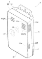
図1〜6に示したように、当該電気機器Xは、機器本体10および当該機器本体10の少なくとも一部を覆う封止体20を有する筺体Yと、筺体Yの内部に設けられ、外部環境の変化を検知する検知部31を配設した基板部30と、封止体20から筺体Yの内部の側に向って立設し、検知部31を収容する収容部22と、を備える。本発明の電気機器Xの水抜き構造は、収容部22に浸入した水を排出する収容部排水路22aを封止体20に沿って形成して構成してある。
As shown in FIGS. 1 to 6, the electrical device X includes a housing Y having a
電気機器Xは、屋内や屋外で壁面に設置する態様であればどのような機器であってもよい。当該壁面に設置する電機機器としては、例えば防災用又は防犯用の警報器が挙げられる。当該警報器は、その内部に外部環境の変化を検知する検知部31を備える。当該検知部31は外部環境の変化を検知するセンサであればよく、このようなセンサとして、酸素センサ、COセンサ、都市ガスセンサなどのガスセンサ、火災センサなどを使用することができるが、これに限られるものではない。
The electric device X may be any device as long as it is installed on the wall surface indoors or outdoors. As an electric equipment installed in the said wall surface, the alarm device for disaster prevention or crime prevention is mentioned, for example. The alarm device includes a
ガスセンサは、被検知ガスを検知するものであればどのような態様であってもよい。例えば酸素センサは酸素ガスを検出でき、COセンサは不完全燃焼で発生する一酸化炭素ガスを検出でき、都市ガスセンサは炭化水素ガス等の漏洩ガスを検出することができるものであれば、公知の半導体式センサ素子や接触燃焼式センサ素子などが使用できる。
火災センサは、温度の上昇を感知する温度センサや、煙感知機能を有する公知の散乱光式煙センサなどが使用できる。
The gas sensor may be in any form as long as it detects the gas to be detected. For example, an oxygen sensor can detect oxygen gas, a CO sensor can detect carbon monoxide gas generated by incomplete combustion, and a city gas sensor can detect a leaked gas such as hydrocarbon gas. A semiconductor sensor element, a contact combustion sensor element, or the like can be used.
As the fire sensor, a temperature sensor that senses an increase in temperature, a known scattered light smoke sensor having a smoke sensing function, or the like can be used.
本実施形態では、電気機器Xとして、COガスの漏洩を検知するガス警報器を厨房の壁面に設置する態様について説明する。当該ガス警報器Xの形状は特に限定されるものではないが、本実施形態では上面視で矩形状であり、厚板状(例えば12×7×2.5cm)の形状を呈するものを例示する。この場合、当該ガス警報器Xは、例えばその長辺を地面に垂直に設置する縦置き姿勢(設置姿勢)によって設置することができる。 This embodiment demonstrates the aspect which installs the gas alarm which detects the leakage of CO gas as the electric equipment X on the wall surface of a kitchen. The shape of the gas alarm device X is not particularly limited, but in the present embodiment, the gas alarm device X has a rectangular shape in a top view and exemplifies a thick plate shape (for example, 12 × 7 × 2.5 cm). . In this case, the gas alarm device X can be installed, for example, in a vertically installed posture (installation posture) in which the long side is installed vertically to the ground.
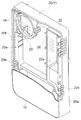
機器本体10は基板部30を収容しており、底面11と側面12とを一体に形成して構成されている。即ち、底面11および側面12とで囲まれた空間に基板部30が収容される。側面12の端部(封止体20の側)には、封止体20と重ね配置される本体周縁端部12aが形成してある。本実施形態では、機器本体10に封止体20を組み付けた際、本体周縁端部12aと封止体20の封止端部21とが重ね配置されたときに、本体周縁端部12aが内側に位置する場合について説明する。
The apparatus
また、本実施形態では、本体周縁端部12aに、ガス警報器Xの周縁に沿うように溝部Bが形成してある場合について説明する。この場合、封止端部21と本体周縁端部12aとが重ね配置されたとき、当該封止端部21は、本体周縁端部12aに形成された溝部Bを覆う。
Moreover, this embodiment demonstrates the case where the groove part B is formed in the main body
本体周縁端部12aには、その全周に亘って複数の防水リブ12bが形成されており、当該溝部Bは、隣接する防水リブ12bどうしの間の空間で構成される。当該溝部Bは、少なくとも一本形成すればよい。本実施形態では、二本の溝部Bを形成した場合について説明する。
A plurality of
封止体20は、機器本体10の少なくとも一部を覆う部材である。本実施形態では、封止体20は、機器本体10の全体を覆う場合について説明する。
The sealing
封止体20には、報知部32が発した警報音を外部に放音するスピーカ開口部24、被検知ガスを検知部31に導入する被検知ガス導入口26、および、スイッチ操作を行うスイッチ押圧部27が形成してあり、封止体20の裏面に形成した凹部には、導光部28や電池29が配設してある。
尚、封止体20の表面には封止板40を貼り付けてある。当該封止板40には、スピーカ開口部24や被検知ガス導入口26に対応するスピーカ開口部44および被検知ガス導入口46がそれぞれ形成してある。
The sealing
A sealing
基板部30には、検知部31、報知部32、LED33およびスイッチ部34などの部品が配設してある。本実施形態では、COガスを検知する検知部31として、電気化学式COセンサを使用した場合について説明する。電気化学式COセンサとは、COガスを、隔膜を通して触媒作用を有する作用電極上に導き、COガスを酸化することによりガス濃度に応じた電圧または電流を出力するセンサである。報知部32は、検知部31からの信号を受けて警報を発するものであればどのような態様であってもよく、例えば圧電スピーカなどを使用することができる。LED33が発した光は、導光部28を介して外部に放出される。
Components such as a
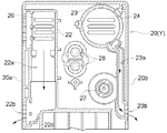
検知部31は、封止体20から筺体Yの内部の側に向って立設した収容部22に収容してある。当該収容部22は、検知部31である電気化学式COセンサを収容できる形態であればその形状は特に限定されるものではなく、本実施形態では、矩形状を呈する場合を例示する。収容部22は、封止体20の裏面から立設し、基板部30によって収容部22の矩形状の開口が塞がれる。当該収容部22に検知部31を収容することで、収容された検知部31を筺体Yの内部空間から隔離することができる。仮に筺体Yの内部に水が浸入したとしても、筺体Yの内部空間から隔離してある検知部31に水が触れ難くなる。
The
また、本発明では、収容部22に浸入した水を排出する収容部排水路22aが封止体20に沿って形成してある。
収容部22は、検知部31である電気化学式COセンサが収容してあり、この電気化学式COセンサにCOガスを導入する被検知ガス導入口26が形成してある。ガス警報器Xを壁面に設置した場合、この被検知ガス導入口26から収容部22の内部に水が浸入する場合がある。しかし、本構成のように収容部22に浸入した水を排出する収容部排水路22aが封止体20に沿って形成してあれば、収容部22に浸入した水を直ちに収容部排水路22aから排出することができる。
尚、収容部22および基板部30の接触部分には、これら部材の隙間を埋めるシール材(図外)を配設してもよい。当該シール材は、例えばPET製の薄膜によって構成し、当該薄膜によって収容部22の矩形状の開口を覆うように配設すればよい。これにより、例えば被検知ガス導入口26から収容部22の内部に水が浸入した場合であっても、収容部22および基板部30の隙間から当該浸入した水が電気機器Xの内部空間に浸入するのを未然に防止できる。
Further, in the present invention, the accommodating
The
A sealing material (not shown) that fills the gap between these members may be disposed at the contact portion between the
収容部排水路22aは、筺体Yの第一側面20aに形成した第一排水口22bに接続する。本構成では、収容部排水路22aの一端が収容部22に接続し、その他端が第一排水口22bに接続する。
仮にガス警報器Xの底面に開口を形成してガス警報器Xを厨房の壁面に配設した場合に、調理中に発生した水蒸気や煙が当該底面の開口からガス警報器Xの内部に侵入する虞がある。しかし、本構成のように第一排水口22bを第一側面20aに形成すれば、上記水蒸気や煙は、当該底面の開口よりガス警報器Xの内部に侵入し難くなる。
The accommodating
If an opening is formed in the bottom surface of the gas alarm device X and the gas alarm device X is disposed on the wall surface of the kitchen, water vapor and smoke generated during cooking enter the gas alarm device X from the opening in the bottom surface. There is a risk of doing. However, if the
収容部排水路22aおよび第一排水口22bの接続位置において、下方に凹設した段部22cが形成してある。本明細書における「下方」とは、ガス警報器Xを設置姿勢の状態にした場合における下方のことをいう。
収容部排水路22aの一端は収容部22に接続しているため、被検知ガス導入口26から収容部22に導入されたCOガスは、収容部排水路22aを経由して第一排水口22bから排出できる。仮にCOガスがガス警報器Xの内部に滞留した状態が続くと、例えば報知部32の警報音が鳴り止むタイミングが遅れることとなる。そのためCOガスをガス警報器Xの外部に素早く排出できるのが好ましい。
また、第一排水口22bには、調理中に発生した油煙がガス警報器Xの内部に侵入するのを防止する油煙フィルタ22dが配設される場合がある。この場合、油煙フィルタの網目に、収容部排水路22aからの水が付着するなどして当該油煙フィルタが目詰まりする虞がある。この場合、COガスが第一排水口22bからガス警報器Xの外部に排出し難くなってしまう。
本構成のように、収容部排水路22aおよび第一排水口22bの接続位置において、下方に凹設した当該段部22cを形成することで、収容部排水路22aからの水が段部22cに溜まり易くなる。そのため、第一排水口22bに油煙フィルタを配設した場合、当該油煙フィルタに水が付着したとしても、油煙フィルタの下方(段部)付近のみに水が付着し易くなるため、油煙フィルタの全体が目詰まりし難くなる。よって本構成では、COガスを、収容部排水路22aを経由して第一排水口22bから確実に排出し易くできる。
尚、油煙フィルタ22dは第一排水口22bに配設される場合があることを説明したが、当該油煙フィルタ22dは第一排水口22bだけでなく、スピーカ開口部24や被検知ガス導入口26などに配設してもよい。
A stepped
Since one end of the accommodating
The
As in this configuration, by forming the
In addition, although it has been described that the
収容部排水路22aは、第一側面20aに対向する第二側面20bに形成した第二排水口23bに接続する。
本構成では、第二排水口23bを第二側面20bに形成してあるため、第一排水口22bと同様に調理中に発生した水蒸気や煙がガス警報器Xの内部に侵入し難い。また、本構成では、収容部排水路22aからの水やCOガスをガス警報器Xの外部に排出する第二排水口23bを更に設けているため、当該水やCOガスをより効率よくガス警報器Xの外部に排出できる。
The accommodating
In this configuration, since the
本実施形態では、ガス警報器Xの周縁Aに、ガス警報器Xの内部に浸入した水を排出できる水抜部Cを形成してある。 In this embodiment, the drainage part C which can discharge | release the water which permeated the inside of the gas alarm device X in the peripheral edge A of the gas alarm device X is formed.
本構成では、水抜部Cが形成してある周縁Aが下向きになるようにガス警報器Xを配置した場合、ガス警報器Xの内部に浸入しようとした水を重力によって水抜部Cから排出することができる。即ち、溝部Bおよび防水リブ12bは、水の浸入方向に対して略直交する方向に設けられているため、防水リブ12bによって浸入してきた雨水等の水を堰き止めることができる。仮に最初の防水リブ12bを越えて雨水等がガス警報器Xの内部空間側に浸入してきた場合でも、これを次の防水リブ12bで堰き止めることができる。堰き止められた水は溝部Bを伝ってガス警報器Xの下方に流れ落ちて水抜部Cに到達し、外部に排出することができる。
In this configuration, when the gas alarm device X is arranged so that the peripheral edge A where the drainage portion C is formed faces downward, the water that is about to enter the gas alarm device X is discharged from the drainage portion C by gravity. be able to. That is, since the groove part B and the
本実施形態では、水抜部Cは、本体周縁端部12aおよび封止端部21をそれぞれ重ね配置したときの隙間としている。
In the present embodiment, the drainage portion C is a gap when the main body
このような隙間は、本体周縁端部12aに形成された溝部Bと通じている。よって、本構成によれば、機器本体10に封止体20を組み付けたときに形成される隙間を水抜部Cとすることができるため、容易に水抜部Cを形成することができる。
Such a gap communicates with a groove B formed in the main body
また、当該隙間は、長辺の長さおよび短辺の長さに亘って形成できるため、水抜部Cを長く形成することができる。これにより、ガス警報器Xの内部に浸入しようとした水を排出できる領域をガス警報器Xの周縁に亘って確保することができる。このような隙間は、通常、細長い線状に形成される。この場合、水抜部Cに到達した水は、隙間を毛管現象により移動し易くなるため、効率よく水を外部に排出し易くなる。 Moreover, since the said clearance gap can be formed over the length of a long side, and the length of a short side, the drain part C can be formed long. Thereby, the area | region which can discharge | emit the water which was going to enter the inside of the gas alarm X can be ensured over the periphery of the gas alarm X. Such a gap is usually formed in an elongated line shape. In this case, since the water that has reached the drainage portion C is likely to move through the gap by capillary action, it is easy to efficiently discharge the water to the outside.
基板部30には、検知部31からの出力信号を受けて報知する報知部32が設けてある。封止体20の裏面には、封止体20から筺体Yの内部の側に向って立設し、報知部32の外周32aの少なくとも一部と係合する筒状部23が設けてある。また、当該筒状部23に浸入した水を排出する筒状部排水路23aが封止体20に沿って形成してあり、当該筒状部排水路23aは第二排水口23bに接続する。
The
報知部32の外周32aには、筒状部23の係合部23cと係合する突起部32bが形成してある。筒状部排水路23aの一端は筒状部23の下方に接続し、他端は第二排水口23bに接続している。当該一端が筒状部23の下方に接続する位置は、設置姿勢における筒状部23の最下位置でもよいが、当該最下位置よりずれた位置でもよい。
本構成では、スピーカ開口部24からガス警報器X(筒状部23)の内部に浸入した水は、直ちに筒状部排水路23aを経由して第二排水口23bからガス警報器Xの外部に排出することができる。
On the
In this configuration, the water that has entered the gas alarm device X (cylindrical portion 23) from the
〔別実施の形態1〕
上述した実施形態では、溝部Bは本体周縁端部12aに形成してある場合について説明したが、これに限らず、封止端部21の側に溝部Bを形成してもよい。
[Another embodiment 1]
In the embodiment described above, the case where the groove portion B is formed in the main body
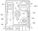
〔別実施の形態2〕
図6に示したように、第一排水口22bおよび第二排水口23bを接続する横断水路25を形成して、収容部排水路22aが第二排水口23bに接続するようにしてもよい。本構成では、収容部排水路22aからの水やCOガスが、第一排水口22bおよび第二排水口23bの何れか排出し易いほうから排出させることができるため、これらの排出効率が高まる。
[Another embodiment 2]
As illustrated in FIG. 6, a
本発明の電気機器の水抜き構造は、屋内や屋外で壁面に設置される防災用又は防犯用の電気機器に利用できる。 The drainage structure of the electric device of the present invention can be used for an electric device for disaster prevention or crime prevention installed on a wall surface indoors or outdoors.
X 電気機器
Y 筺体
10 機器本体
20 封止体
20a 第一側面
20b 第二側面
22 収容部
22a 収容部排水路
22b 第一排水口
22c 段部
23 筒状部
23a 筒状部排水路
23b 第二排水口
30 基板部
31 検知部
32 報知部
32a 外周
X Electrical
Claims (5)
前記筺体の内部に設けられ、外部環境の変化を検知する検知部を配設した基板部と、
前記封止体から前記筺体の内部の側に向って立設し、前記検知部を収容する収容部と、を備え、
前記収容部に浸入した水を排出する収容部排水路を前記封止体に沿って形成した電気機器の水抜き構造。 A housing having a device body and a sealing body covering at least a part of the device body;
A board part provided inside the housing and provided with a detection part for detecting a change in the external environment;
A storage unit that is erected from the sealing body toward the inside of the housing and stores the detection unit;
A drainage structure for an electrical device in which a housing drainage channel for discharging water that has entered the housing is formed along the sealing body.
前記封止体から前記筺体の内部の側に向って立設し、前記報知部の外周の少なくとも一部と係合する筒状部と、を備え、
当該筒状部に浸入した水を排出する筒状部排水路を前記封止体に沿って形成してあり、前記筒状部排水路は前記第二排水口に接続する請求項4に記載の電気機器の水抜き構造。 A notification unit for receiving and reporting an output signal from the detection unit;
A cylindrical portion that is erected from the sealing body toward the inside of the housing and engages with at least a part of the outer periphery of the notification portion;
The cylindrical part drainage channel which discharges the water which permeated the said cylindrical part is formed along the said sealing body, The said cylindrical part drainage channel is connected to said 2nd drainage port. Water drainage structure for electrical equipment.
Priority Applications (1)
| Application Number | Priority Date | Filing Date | Title |
|---|---|---|---|
| JP2012054876A JP5884980B2 (en) | 2012-03-12 | 2012-03-12 | Water drainage structure for electrical equipment |
Applications Claiming Priority (1)
| Application Number | Priority Date | Filing Date | Title |
|---|---|---|---|
| JP2012054876A JP5884980B2 (en) | 2012-03-12 | 2012-03-12 | Water drainage structure for electrical equipment |
Related Child Applications (1)
| Application Number | Title | Priority Date | Filing Date |
|---|---|---|---|
| JP2015246962A Division JP6095757B2 (en) | 2015-12-18 | 2015-12-18 | Water drainage structure for electrical equipment |
Publications (2)
| Publication Number | Publication Date |
|---|---|
| JP2013190859A true JP2013190859A (en) | 2013-09-26 |
| JP5884980B2 JP5884980B2 (en) | 2016-03-15 |
Family
ID=49391065
Family Applications (1)
| Application Number | Title | Priority Date | Filing Date |
|---|---|---|---|
| JP2012054876A Active JP5884980B2 (en) | 2012-03-12 | 2012-03-12 | Water drainage structure for electrical equipment |
Country Status (1)
| Country | Link |
|---|---|
| JP (1) | JP5884980B2 (en) |
Cited By (3)
| Publication number | Priority date | Publication date | Assignee | Title |
|---|---|---|---|---|
| US20210105549A1 (en) * | 2019-04-02 | 2021-04-08 | Gopro, Inc. | Audio component drainage system for image capture device |
| JP2021068341A (en) * | 2019-10-28 | 2021-04-30 | 新コスモス電機株式会社 | Alarm unit |
| CN115985034A (en) * | 2022-11-30 | 2023-04-18 | 江苏拓米洛高端装备股份有限公司 | A smoke detection and alarm device and battery test box |
Citations (3)
| Publication number | Priority date | Publication date | Assignee | Title |
|---|---|---|---|---|
| JP2003296830A (en) * | 2002-03-29 | 2003-10-17 | Matsushita Electric Works Ltd | Crime prevention apparatus |
| JP2006138523A (en) * | 2004-11-11 | 2006-06-01 | Matsushita Electric Ind Co Ltd | Condensation sensor and heat pump system using it |
| JP2013050752A (en) * | 2011-08-30 | 2013-03-14 | Yazaki Energy System Corp | Alarm |
-
2012
- 2012-03-12 JP JP2012054876A patent/JP5884980B2/en active Active
Patent Citations (3)
| Publication number | Priority date | Publication date | Assignee | Title |
|---|---|---|---|---|
| JP2003296830A (en) * | 2002-03-29 | 2003-10-17 | Matsushita Electric Works Ltd | Crime prevention apparatus |
| JP2006138523A (en) * | 2004-11-11 | 2006-06-01 | Matsushita Electric Ind Co Ltd | Condensation sensor and heat pump system using it |
| JP2013050752A (en) * | 2011-08-30 | 2013-03-14 | Yazaki Energy System Corp | Alarm |
Cited By (6)
| Publication number | Priority date | Publication date | Assignee | Title |
|---|---|---|---|---|
| US20210105549A1 (en) * | 2019-04-02 | 2021-04-08 | Gopro, Inc. | Audio component drainage system for image capture device |
| US11665457B2 (en) * | 2019-04-02 | 2023-05-30 | Gopro, Inc. | Audio component drainage system for image capture device |
| US12556849B2 (en) | 2019-04-02 | 2026-02-17 | Gopro, Inc. | Audio component drainage system for image capture device |
| JP2021068341A (en) * | 2019-10-28 | 2021-04-30 | 新コスモス電機株式会社 | Alarm unit |
| JP7441026B2 (en) | 2019-10-28 | 2024-02-29 | 新コスモス電機株式会社 | alarm |
| CN115985034A (en) * | 2022-11-30 | 2023-04-18 | 江苏拓米洛高端装备股份有限公司 | A smoke detection and alarm device and battery test box |
Also Published As
| Publication number | Publication date |
|---|---|
| JP5884980B2 (en) | 2016-03-15 |
Similar Documents
| Publication | Publication Date | Title |
|---|---|---|
| JP5921198B2 (en) | sensor | |
| TWI442346B (en) | Photoelectric smoke detector | |
| JP5884980B2 (en) | Water drainage structure for electrical equipment | |
| JP5943253B2 (en) | Housing structure of electrical equipment | |
| JP5892748B2 (en) | Alarm | |
| JP6095757B2 (en) | Water drainage structure for electrical equipment | |
| JP5887653B2 (en) | Water drainage structure for electrical equipment | |
| JP5810444B2 (en) | smoke detector | |
| JP2014086962A (en) | Waterproof structure of electrical equipment | |
| JP5899578B2 (en) | Housing structure of electrical equipment | |
| JP6064221B2 (en) | Housing structure of electrical equipment | |
| JP5818666B2 (en) | Portable gas alarm | |
| JP6568725B2 (en) | Fire detector | |
| JP5849866B2 (en) | Water drainage structure for electrical equipment | |
| JP2018088201A (en) | Fire sensor | |
| JP2018088202A (en) | Fire sensor | |
| JP5726627B2 (en) | Fire detector and assembly method | |
| JP2020013396A (en) | Fire detector | |
| JP2010086378A (en) | Photoelectric smoke detector | |
| KR20140001505U (en) | Independent alarm type fire detector | |
| JP5894230B2 (en) | sensor | |
| JP2007102555A (en) | Waterproof structure of disaster prevention crime prevention equipment | |
| JP2020016977A (en) | Fire detector | |
| JP2011070389A (en) | Fire alarm | |
| JP2014002664A (en) | Drain structure of electrical apparatus |
Legal Events
| Date | Code | Title | Description |
|---|---|---|---|
| A621 | Written request for application examination |
Free format text: JAPANESE INTERMEDIATE CODE: A621 Effective date: 20141219 |
|
| A977 | Report on retrieval |
Free format text: JAPANESE INTERMEDIATE CODE: A971007 Effective date: 20151028 |
|
| A131 | Notification of reasons for refusal |
Free format text: JAPANESE INTERMEDIATE CODE: A131 Effective date: 20151110 |
|
| A521 | Request for written amendment filed |
Free format text: JAPANESE INTERMEDIATE CODE: A523 Effective date: 20151218 |
|
| TRDD | Decision of grant or rejection written | ||
| A01 | Written decision to grant a patent or to grant a registration (utility model) |
Free format text: JAPANESE INTERMEDIATE CODE: A01 Effective date: 20160112 |
|
| A61 | First payment of annual fees (during grant procedure) |
Free format text: JAPANESE INTERMEDIATE CODE: A61 Effective date: 20160126 |
|
| R150 | Certificate of patent or registration of utility model |
Ref document number: 5884980 Country of ref document: JP Free format text: JAPANESE INTERMEDIATE CODE: R150 |
|
| R250 | Receipt of annual fees |
Free format text: JAPANESE INTERMEDIATE CODE: R250 |
|
| R250 | Receipt of annual fees |
Free format text: JAPANESE INTERMEDIATE CODE: R250 |
|
| R250 | Receipt of annual fees |
Free format text: JAPANESE INTERMEDIATE CODE: R250 |
|
| R250 | Receipt of annual fees |
Free format text: JAPANESE INTERMEDIATE CODE: R250 |
|
| R250 | Receipt of annual fees |
Free format text: JAPANESE INTERMEDIATE CODE: R250 |
|
| R250 | Receipt of annual fees |
Free format text: JAPANESE INTERMEDIATE CODE: R250 |
|
| R250 | Receipt of annual fees |
Free format text: JAPANESE INTERMEDIATE CODE: R250 |
|
| R250 | Receipt of annual fees |
Free format text: JAPANESE INTERMEDIATE CODE: R250 |