本明細書および添付図面の記載により、少なくとも以下の事項が明らかとなる。
At least the following matters will become apparent from the description of this specification and the accompanying drawings.
===台間機===
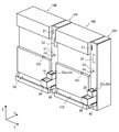
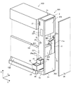
以下、図1、図2を参照して、本実施形態における台間機について説明する。図1は、本実施形態における複数の台間機と遊技機とを示す斜視図である。図2は、本実施形態における台間機と遊技機とを示す斜視図である。尚、図2は、側面板2bが取り外された状態の台間機200を示している。傾斜板28の一部、蝶番231、開口26aは、見えない状態となっているが、説明の便宜上、点線で示されている。
=== Between machines ===
Hereinafter, with reference to FIG. 1 and FIG. 2, a table machine in the present embodiment will be described. FIG. 1 is a perspective view showing a plurality of intermediary machines and gaming machines in the present embodiment. FIG. 2 is a perspective view showing a table machine and a gaming machine in the present embodiment. FIG. 2 shows the inter-machine 200 with the side plate 2b removed. A part of the inclined plate 28, the hinge 231 and the opening 26a are invisible, but are shown by dotted lines for convenience of explanation.
台間機200(メダル計数機)は、遊技機100で使用されるメダルMD(図3)を貸し出したり、台間機200内に投入されたメダルMDの枚数を計数したりする機能を兼ね備えた装置であることとする。尚、本実施形態において、Z軸は、台間機200が立設する垂直方向に沿う軸であり、上側に向かう方向を+Zとし、下側に向かう方向を−Zとする。Y軸は、台間機200の正面板2aと背面板2cとに直交する方向に沿う軸であり、正面板2aから背面板2cに向かう方向を+Yとし、背面板2cから正面板2aに向かう方向を−Yとする。X軸は、台間機200と遊技機100とが隣接する方向に沿う軸であり、一方に向かう方向を+Xとし、他方に向かう方向を−Xとする。
The intermediary machine 200 (medal counting machine) has a function of lending medal MDs (FIG. 3) used in the gaming machine 100 and counting the number of medal MDs inserted into the intermediary machine 200. Suppose that it is a device. In the present embodiment, the Z axis is an axis along the vertical direction in which the inter-machine 200 is erected, and the upward direction is + Z and the downward direction is -Z. The Y axis is an axis along a direction orthogonal to the front plate 2a and the back plate 2c of the inter-machine 200, and the direction from the front plate 2a to the back plate 2c is + Y, and the back plate 2c goes to the front plate 2a. Let the direction be -Y. The X axis is an axis along the direction in which the inter-table machine 200 and the gaming machine 100 are adjacent to each other, and the direction toward one is + X and the direction toward the other is −X.
台間機200と、例えばスロットマシン等の遊技機100とは、遊技場(不図示)内に複数台交互に隣接するように設置される。台間機200は、筐体2、カード挿入口21、タッチパネル22、錠23、トレイ25(第2受け皿)、トレイ26(第1受け皿)、容器45、ユニット201、計数ユニット203、ホッパ202(メダルホッパ)、リフト5を有している。
The inter-machine 200 and the gaming machine 100 such as a slot machine are installed so as to be alternately adjacent to each other in a game hall (not shown). The inter-machine 200 includes a housing 2, a card insertion slot 21, a touch panel 22, a lock 23, a tray 25 (second tray), a tray 26 (first tray), a container 45, a unit 201, a counting unit 203, a hopper 202 ( Medal hopper) and a lift 5.
筐体2は、略矩形柱形状を呈する。筐体2は、内部にユニット201、計数ユニット203、ホッパ202、リフト5を収容できるように、中空構造となっている。筐体2の正面板2aには、カード挿入口21、タッチパネル22、錠23、開口25a、25b(排出口)、開口26a(投入口)、トレイ25、26、容器45が設けられる。
The housing 2 has a substantially rectangular column shape. The housing 2 has a hollow structure so that the unit 201, the counting unit 203, the hopper 202, and the lift 5 can be accommodated therein. The front plate 2a of the housing 2 is provided with a card insertion port 21, a touch panel 22, a lock 23, openings 25a and 25b (discharge ports), an opening 26a (input port), trays 25 and 26, and a container 45.
開口26aは、メダルMDの枚数を計数するために、メダルMDを筐体2内に投入するための孔である。トレイ26は、開口26aにメダルMDを案内するための受け皿である。開口25a、25bは、筐体2内のメダルMDを排出するための、開口26aよりも上側の位置に設けられる孔である。トレイ25は、開口25a、25bから排出されるメダルMDを受け取るための、トレイ26よりも上側の位置に設けられる受け皿である。尚、開口25a、25b、26a、トレイ25、26については、後述する。
The opening 26 a is a hole for inserting the medal MD into the housing 2 in order to count the number of medals MD. The tray 26 is a tray for guiding the medal MD to the opening 26a. The openings 25a and 25b are holes provided at positions above the opening 26a for discharging the medal MD in the housing 2. The tray 25 is a tray provided at a position above the tray 26 for receiving medals MD discharged from the openings 25a and 25b. The openings 25a, 25b, 26a and the trays 25, 26 will be described later.
容器45は、傾斜板28の孔282(図3)から落下する塵埃を収容するための塵埃収容容器である。尚、傾斜板28、孔282、容器45については、後述する。
The container 45 is a dust container for storing dust falling from the hole 282 (FIG. 3) of the inclined plate 28. The inclined plate 28, the hole 282, and the container 45 will be described later.
カード挿入口21は、台間機200で計数されたメダルMDの枚数を示す情報が記憶される、例えばICカードを挿入するための孔である。尚、例えば、カード挿入口21に挿入されたICカードには、ユニット201内の書込装置(不図示)によって、メダルMDの枚数を示す情報が書き込まれるものとする。
The card insertion slot 21 is a hole for inserting, for example, an IC card, in which information indicating the number of medals MD counted by the interstage machine 200 is stored. For example, it is assumed that information indicating the number of medals MD is written on the IC card inserted into the card insertion slot 21 by a writing device (not shown) in the unit 201.
タッチパネル22には、例えば、台間機200の上側に設けられるビルバリ(不図示)に投入された金銭の額に基づいて、メダルMDを貸し出すための貸出釦のイメージが表示される。
On the touch panel 22, for example, an image of a lending button for lending medal MD is displayed based on the amount of money inserted into a bill burr (not shown) provided on the upper side of the inter-machine 200.
錠23は、正面板2aの開閉を禁止したり許可したりするために正面板2aに設けられる。ここで、正面板2aは、例えば、略矩形形状を呈する平板であり、正面板2aの他方側の縁が、側面板2eにおける正面側(−Y)の縁に、複数の蝶番231によって取り付けられている。つまり、正面板2aは、正面板2aの他方側の縁における複数の蝶番231を軸に、開閉自在に筐体2に取り付けられている。例えば、正面板2aを閉じた状態で、鍵24を用いて錠23を施錠した場合、正面板2aは開けない状態となる。又、例えば、鍵24を用いて錠23を開錠した場合、正面板2aは開閉できる状態となる。
The lock 23 is provided on the front plate 2a in order to prohibit or permit the opening and closing of the front plate 2a. Here, the front plate 2a is, for example, a flat plate having a substantially rectangular shape, and the other side edge of the front plate 2a is attached to the front side (-Y) edge of the side plate 2e by a plurality of hinges 231. ing. That is, the front plate 2a is attached to the housing 2 so as to be openable and closable around a plurality of hinges 231 at the other edge of the front plate 2a. For example, when the front panel 2a is closed and the lock 23 is locked using the key 24, the front panel 2a cannot be opened. For example, when the lock 23 is unlocked using the key 24, the front plate 2a can be opened and closed.
ホッパ202は、内部に貸し出し用のメダルMDが貯留される容器である。ホッパ202については、後述する。
The hopper 202 is a container in which lent medals MD are stored. The hopper 202 will be described later.
リフト5は、筐体2内に投入されたメダルMDを、下側から上側に搬送する装置である。尚、リフト5については、後述する。
The lift 5 is a device that conveys the medal MD inserted into the housing 2 from the lower side to the upper side. The lift 5 will be described later.
===開口、トレイ===
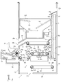
以下、図2、図3を参照して、本実施形態における開口、トレイについて説明する。図3は、本実施形態における台間機の内部を示す図である。尚、電極141乃至143、搬送ベルト58、ローラ581、582、振分装置59、見えない状態となっているが、説明の便宜上、点線で示されている。
=== Open, tray ===
Hereinafter, the opening and the tray in the present embodiment will be described with reference to FIGS. 2 and 3. FIG. 3 is a diagram showing the inside of the interpolator in the present embodiment. The electrodes 141 to 143, the conveyor belt 58, the rollers 581 and 582, and the sorting device 59 are in an invisible state, but are shown by dotted lines for convenience of explanation.
開口26aは、メダルMDが投入される孔である。開口26aから筐体2内に投入されたメダルMDは、計数ユニット203によって計数される。計数ユニット203については、後述する。開口26aは、遊技機100の遊技者が、メダルMDを投入し易い位置に設けられる。開口26aは、例えば、正面板2aにおける略中央よりも下側(−Z)に設けられる。開口26aの径は、複数枚のメダルMDを同時に筐体2内に投入できる程度に設定される。
The opening 26a is a hole into which the medal MD is inserted. The medals MD inserted into the housing 2 from the opening 26a are counted by the counting unit 203. The counting unit 203 will be described later. The opening 26a is provided at a position where the player of the gaming machine 100 can easily insert the medal MD. The opening 26a is provided, for example, on the lower side (−Z) than the approximate center of the front plate 2a. The diameter of the opening 26a is set to such an extent that a plurality of medals MD can be put into the housing 2 at the same time.
トレイ26は、開口26aにメダルMDを案内するために、開口26aの近傍に設けられる。トレイ26は、トレイ26内のメダルMDが開口26aに投入されるように、開口26aの手前側(−Y方向)に連続して設けられる。トレイ26は、正面板2aにおける手前側の面から手前側に向かって突出するように設けられる。つまり、トレイ26は、開口26aよりも手前の位置において、メダルMDを開口26aに案内することとなる。トレイ26のY軸方向の長さは、トレイ26内に配設されている傾斜板28が露出するように、トレイ25のY軸方向の長さよりも長くなるように設定されている。尚、傾斜板28については、後述する。トレイ26のX軸方向の幅は、トレイ26内のメダルMDを開口26aに確実に案内できるように、開口26aのX軸方向の幅と同程度に設定される。
The tray 26 is provided in the vicinity of the opening 26a in order to guide the medal MD to the opening 26a. The tray 26 is continuously provided on the front side (−Y direction) of the opening 26a so that the medals MD in the tray 26 are inserted into the opening 26a. The tray 26 is provided so as to protrude from the near side surface of the front plate 2a toward the near side. That is, the tray 26 guides the medal MD to the opening 26a at a position before the opening 26a. The length of the tray 26 in the Y-axis direction is set to be longer than the length of the tray 25 in the Y-axis direction so that the inclined plate 28 disposed in the tray 26 is exposed. The inclined plate 28 will be described later. The width of the tray 26 in the X-axis direction is set to be approximately the same as the width of the opening 26a in the X-axis direction so that the medal MD in the tray 26 can be reliably guided to the opening 26a.
開口25bは、判定装置60で偽と判定されたメダルMDが排出される孔である。尚、判定装置60については、後述する。開口25bから排出されたメダルMDは、トレイ25内に収容されることとなる。開口25bは、遊技機100の遊技者が筐体2から排出されるメダルMDを視認しやすいように、開口26aよりも上側(+Z)の位置に設けられる。
The opening 25b is a hole through which the medal MD determined to be false by the determination device 60 is discharged. The determination device 60 will be described later. The medal MD discharged from the opening 25b is accommodated in the tray 25. The opening 25b is provided at a position (+ Z) above the opening 26a so that the player of the gaming machine 100 can easily see the medal MD discharged from the housing 2.
開口25aは、ホッパ202内に貯留されているメダルMDを、筐体2外へ排出するための孔である。開口25aから排出されたメダルMDは、トレイ25内に収容されることとなる。開口25aは、開口25bから排出されたメダルMDと同じトレイ25内に収容されるように、正面板2aにおける開口25bの近傍に設けられる。開口25aは、例えば、搬送ベルト65よりも上側に設けられているホッパ202内のメダルMDが、当該メダルMDの自重によって排出されるように、開口25bの上側に設けられる。
The opening 25 a is a hole for discharging the medal MD stored in the hopper 202 to the outside of the housing 2. The medal MD discharged from the opening 25a is accommodated in the tray 25. The opening 25a is provided in the vicinity of the opening 25b in the front plate 2a so as to be accommodated in the same tray 25 as the medal MD discharged from the opening 25b. The opening 25a is provided above the opening 25b so that, for example, the medal MD in the hopper 202 provided above the transport belt 65 is discharged by the weight of the medal MD.
トレイ25は、開口25a、25bから排出されたメダルMDを受け取るために、開口25a、25bの近傍に設けられる。つまり、トレイ25は、開口25aから排出されたメダルMD、及び、開口25bから排出されたメダルMDに兼用の受け皿として設けられる。トレイ25は、開口25a、25bから排出されたメダルMDを受け取れるように、開口25a、25bの手前側に連続して設けられる。トレイ25は、遊技機100の遊技者が筐体2から排出されてトレイ25内に収容されたメダルMDを視認しやすいように、トレイ26の上側の位置に設けられる。トレイ25は、正面板2aにおける手前側の面から手前側に向かって突出するように設けられる。つまり、トレイ25は、開口25a、25bよりも手前の位置において、開口25a、25bから排出されるメダルMDを受け取ることとなる。トレイ25、26は、垂直方向(Z軸)に並設されることとなる。トレイ25は、トレイ25におけるメダルMDを収容する凹部の底25eの高さが、開口25bの高さよりも低くなるように設けられる。トレイ25の下部(−Z)は、開口26aの近傍に設けられる羽根車4を避けるように、上側に向かって抉られたような形状を呈する。尚、羽根車4については、後述する。トレイ25の下部における傾斜板28と対向する一部25dは、下側に向かって突出している。トレイ25は、例えば、トレイ25の一部25dと傾斜板28との間に、メダルMDを通過させ、且つ、外部から筐体2の内部への悪戯を防止できる程度の隙間ができるように、設けられる。トレイ25のX軸方向の幅は、開口25a、25bから排出されたメダルMDを確実に受け取れるように、開口25a、25bのX軸方向の幅よりも長く設定されている。
The tray 25 is provided in the vicinity of the openings 25a and 25b in order to receive the medals MD discharged from the openings 25a and 25b. In other words, the tray 25 is provided as a dual-purpose tray for the medal MD discharged from the opening 25a and the medal MD discharged from the opening 25b. The tray 25 is continuously provided in front of the openings 25a and 25b so as to receive the medals MD discharged from the openings 25a and 25b. The tray 25 is provided at a position above the tray 26 so that the player of the gaming machine 100 can easily see the medals MD that are ejected from the housing 2 and accommodated in the tray 25. The tray 25 is provided so as to protrude from the near side surface of the front plate 2a toward the near side. That is, the tray 25 receives the medals MD discharged from the openings 25a and 25b at a position before the openings 25a and 25b. The trays 25 and 26 are juxtaposed in the vertical direction (Z axis). The tray 25 is provided such that the height of the bottom 25e of the recess for receiving the medal MD in the tray 25 is lower than the height of the opening 25b. The lower part (-Z) of the tray 25 has a shape that is rolled up so as to avoid the impeller 4 provided in the vicinity of the opening 26a. The impeller 4 will be described later. A part 25d facing the inclined plate 28 in the lower part of the tray 25 protrudes downward. The tray 25 has, for example, a gap between the portion 25d of the tray 25 and the inclined plate 28 so that the medal MD can pass and a mischief from the outside to the inside of the housing 2 can be prevented. Provided. The width of the tray 25 in the X-axis direction is set longer than the width of the openings 25a and 25b in the X-axis direction so that the medals MD discharged from the openings 25a and 25b can be reliably received.
===傾斜板、孔、容器===
以下、図2、図3を参照して、本実施形態における傾斜板、孔について説明する。
傾斜板28は、トレイ26内のメダルMDを筐体2内へ搬送するための、例えば略矩形形状を呈する平板である。傾斜板28は、傾斜板28の背面側の一部が略水平となるように折り曲げられた形状を呈する。傾斜板28は、トレイ26内のメダルMDを開口26aに搬送できるように、トレイ26内に取り付けられる。傾斜板28は、傾斜板28の正面側(−Y)の縁の高さが、傾斜板28の背面側(+Y)の縁の高さよりも高くなるように、トレイ26内に取り付けられる。傾斜板28の正面側の縁は、傾斜板28の上面における手前側の一部がトレイ25よりも手前側で露出するように、トレイ26の内側面26cに接続される。よって、トレイ25との干渉をさけてトレイ26内にメダルMDを投入できることとなる。尚、傾斜板28の背面側の縁は、搬送ベルト62の上面における正面側の縁の近傍に設けられる。尚、傾斜板28の背面側の縁の高さは、メダルMDが傾斜板28上における背面側の縁から搬送ベルト62の上面に案内されるように、搬送ベルト62の上面の高さと同様な高さに設定される。傾斜板28の上面の高さは、正面側から背面側に向かうにつれて低くなっている。よって、トレイ26内のメダルMDは、自重によって傾斜板28上を流下して開口26aへ搬送されることとなる。尚、例えば、傾斜板28は、トレイ26と一体的に形成されるものとしてもよい。
=== Inclined plate, hole, container ===
Hereinafter, the inclined plate and the hole in the present embodiment will be described with reference to FIGS.
The inclined plate 28 is a flat plate having a substantially rectangular shape, for example, for conveying the medal MD in the tray 26 into the housing 2. The inclined plate 28 has a shape that is bent so that a part of the rear side of the inclined plate 28 is substantially horizontal. The inclined plate 28 is attached in the tray 26 so that the medal MD in the tray 26 can be conveyed to the opening 26a. The inclined plate 28 is mounted in the tray 26 so that the height of the edge on the front side (−Y) of the inclined plate 28 is higher than the height of the edge on the back side (+ Y) of the inclined plate 28. The front side edge of the inclined plate 28 is connected to the inner side surface 26 c of the tray 26 so that a part of the front side of the upper surface of the inclined plate 28 is exposed on the front side of the tray 25. Therefore, the medal MD can be inserted into the tray 26 while avoiding interference with the tray 25. Note that the rear side edge of the inclined plate 28 is provided in the vicinity of the front side edge on the upper surface of the transport belt 62. The height of the edge on the back surface of the inclined plate 28 is the same as the height of the upper surface of the conveyor belt 62 so that the medal MD is guided from the edge on the inclined surface 28 to the upper surface of the conveyor belt 62. Set to height. The height of the upper surface of the inclined plate 28 becomes lower from the front side toward the back side. Therefore, the medal MD in the tray 26 flows down on the inclined plate 28 by its own weight and is conveyed to the opening 26a. For example, the inclined plate 28 may be formed integrally with the tray 26.
孔282は、傾斜板28上を流下してきた塵埃を傾斜板28の下側(−Z)に落下させるための、傾斜板28に形成される排出孔である。孔282は、筐体2の内部に塵埃が入り込むのを防止するために、傾斜板28における背面側の一部に形成される。孔282は、開口26aよりも手前側に設けられる。孔282の径は、メダルMDの下流側への搬送が規制されないように、メダルMDの径よりも十分に小さくなるように設定されているものとする。孔282は、例えば、メダルMDが傾斜板28上を流下する方向と交差する方向(X軸)に沿って複数形成される。尚、例えば、孔282の個数は一つであってもよい。孔282の形状は、例えば、略円形状であっても、長孔形状であっても、略矩形形状であってもよい。
The hole 282 is a discharge hole formed in the inclined plate 28 for allowing the dust flowing down on the inclined plate 28 to fall to the lower side (−Z) of the inclined plate 28. The hole 282 is formed in a part on the back side of the inclined plate 28 in order to prevent dust from entering the inside of the housing 2. The hole 282 is provided in front of the opening 26a. It is assumed that the diameter of the hole 282 is set to be sufficiently smaller than the diameter of the medal MD so that the conveyance of the medal MD to the downstream side is not restricted. For example, a plurality of holes 282 are formed along the direction (X axis) intersecting the direction in which the medal MD flows down on the inclined plate 28. For example, the number of holes 282 may be one. The shape of the hole 282 may be, for example, a substantially circular shape, a long hole shape, or a substantially rectangular shape.
容器45は、孔282を介して傾斜板28の上側から下側へ落下する塵埃を収容するための塵埃収容容器である。容器45は、孔282を介して落下する塵埃を収容できるように、トレイ26の下側における孔282と対向する位置に設けられる。容器45は、容器45内に収容された塵埃を捨てるために容器45を取り外せるように、筐体2に着脱可能に取り付けられていることとする。
The container 45 is a dust container for storing dust that falls from the upper side to the lower side of the inclined plate 28 through the hole 282. The container 45 is provided at a position facing the hole 282 on the lower side of the tray 26 so that dust falling through the hole 282 can be accommodated. It is assumed that the container 45 is detachably attached to the housing 2 so that the container 45 can be removed in order to throw away the dust accommodated in the container 45.
===羽根車===
以下、図3を参照して、本実施形態における羽根車について説明する。
羽根車4は、傾斜板28上を傾斜板28における下流側の端まで流下してきたメダルMDを、搬送ベルト62の上面に案内するための装置である。羽根車4は、複数の羽根41、回転軸42を有する。回転軸42は、筐体2の側面板2b及び側面板2eと直交する方向(X軸)に沿うように、傾斜板28よりも上側(+Z)に設けられる。羽根41は、メダルMDを、傾斜板28上の下流側(+Y)の端から、搬送ベルト62の上面に案内するための部材であり、回転軸42から放射状にのびるような形状を呈する。尚、羽根41の先端は、例えば、回転軸42を中心に羽根車4が回転して羽根41の先端と傾斜板28の上面とが接触した際に、羽根車4の回転が止まらないように、例えばゴム等の弾性材を用いて形成してもよい。ここで、回転軸42には、羽根車4が回転軸42を中心に+X方向から−X方向に向かって見て反時計回り方向(以下、「A1方向」と称する)に回転するように、モータ(不図示)(以下、「羽根車4のモータ」と称する)から回転駆動力が加えられるものとする。羽根車4のモータの起動及び停止は夫々、制御装置9から出力される起動信号及び停止信号によって制御されるものとする。尚、制御装置9については、後述する。例えば、羽根車4が回転軸42を中心にA1方向に回転した場合、傾斜板28上の下流側の端まで流下してきたメダルMDの正面側の縁は、羽根41の先端における背面側の面によって、正面側から背面側に向かって押されることとなる。よって、メダルMDは羽根41によって、搬送ベルト62の上面に載置されるように、正面側から背面側に向かってくりだされることとなる。つまり、傾斜板28上の下流側の端まで流下してきたメダルMDは、羽根車4よって正面側から背面側に向かって案内されて、搬送ベルト62の上面に搬送されることとなる。
=== Impeller ===
Hereinafter, with reference to FIG. 3, the impeller in this embodiment is demonstrated.
The impeller 4 is a device for guiding the medal MD that has flowed down on the inclined plate 28 to the downstream end of the inclined plate 28 to the upper surface of the conveyor belt 62. The impeller 4 has a plurality of blades 41 and a rotation shaft 42. The rotation shaft 42 is provided on the upper side (+ Z) of the inclined plate 28 so as to be along a direction (X axis) orthogonal to the side plate 2b and the side plate 2e of the housing 2. The blade 41 is a member for guiding the medal MD from the downstream side (+ Y) end on the inclined plate 28 to the upper surface of the transport belt 62, and has a shape extending radially from the rotation shaft 42. For example, when the impeller 4 rotates around the rotation shaft 42 and the tip of the blade 41 comes into contact with the upper surface of the inclined plate 28, the tip of the blade 41 does not stop the rotation of the impeller 4. For example, you may form using elastic materials, such as rubber | gum. Here, the impeller 4 rotates in the counterclockwise direction (hereinafter referred to as “A1 direction”) when viewed from the + X direction toward the −X direction around the rotation shaft 42. It is assumed that a rotational driving force is applied from a motor (not shown) (hereinafter referred to as “motor of impeller 4”). The start and stop of the motor of the impeller 4 are controlled by a start signal and a stop signal output from the control device 9, respectively. The control device 9 will be described later. For example, when the impeller 4 rotates about the rotation shaft 42 in the A1 direction, the edge on the front side of the medal MD flowing down to the downstream end on the inclined plate 28 is the surface on the back side at the tip of the blade 41. By this, it will be pushed toward the back side from the front side. Therefore, the medal MD is pulled out from the front side toward the back side by the blades 41 so as to be placed on the upper surface of the transport belt 62. That is, the medal MD that has flowed down to the downstream end on the inclined plate 28 is guided from the front side to the back side by the impeller 4 and is conveyed to the upper surface of the conveyance belt 62.
===計数ユニット===
以下、図3を参照して、本実施形態における計数ユニットについて説明する。
計数ユニット203(図2)は、開口26aから投入されたメダルMDの真偽を判定したり、当該メダルMDの枚数を計数したりする機能を有する装置である。計数ユニット203は、判定装置60、計数装置60c、搬送装置6、振分装置7を有する。
=== Counting unit ===
Hereinafter, the counting unit in the present embodiment will be described with reference to FIG.
The counting unit 203 (FIG. 2) is a device having a function of determining the authenticity of the medal MD inserted from the opening 26a and counting the number of the medal MD. The counting unit 203 includes a determination device 60, a counting device 60 c, a transport device 6, and a sorting device 7.
搬送装置6は、開口26aに投入されたメダルMDを、正面側(−Y)から背面側(+Y)に搬送したり、背面側から正面側に搬送したりする装置である。尚、搬送装置6については、後述する。
The transport device 6 is a device that transports the medal MD inserted into the opening 26a from the front side (-Y) to the back side (+ Y) or from the back side to the front side. The transport device 6 will be described later.
振分装置7は、メダルMDの搬送先を切り替える装置である。尚、振分装置7については、後述する。
The sorting device 7 is a device that switches the transport destination of the medal MD. The distribution device 7 will be described later.
判定装置60は、メダルMDの真偽を判定する装置である。メダルMDの真偽の判定とは、メダルMDが遊技機100用のメダルであるか否かを判定することである。判定装置60は、例えば、基台61上を正面側から背面側へ搬送されるメダルMD夫々の一方の面を撮影するためのCCDカメラ(不図示)を有し、当該CCDカメラによって撮影されたメダルMDの画像に基づいて、メダルMDの真偽を夫々判定する。尚、メダルMDの搬送については、後述する。尚、例えば、判定装置60は、基台61上のメダルMDを検出する磁気センサ(不図示)を有し、当該磁気センサの出力に基づいて、メダルMDの真偽を夫々判定することとしてもよい。判定装置60は、基台61上を正面側から背面側へ搬送される各メダルMDの真偽を示す判定信号を出力するものとする。
The determination device 60 is a device that determines the authenticity of the medal MD. The authenticity determination of the medal MD is to determine whether the medal MD is a medal for the gaming machine 100 or not. The determination device 60 has, for example, a CCD camera (not shown) for photographing one surface of each medal MD conveyed on the base 61 from the front side to the back side, and was photographed by the CCD camera. The authenticity of the medal MD is determined based on the image of the medal MD. The conveyance of the medal MD will be described later. For example, the determination device 60 may include a magnetic sensor (not shown) that detects the medal MD on the base 61 and may determine the authenticity of the medal MD based on the output of the magnetic sensor. Good. The determination device 60 outputs a determination signal indicating the authenticity of each medal MD conveyed on the base 61 from the front side to the back side.
計数装置60cは、メダルMDの枚数を計数する装置である。計数装置60cは、例えば、基台61上を正面側から背面側へ搬送されるメダルMDを検出する磁気センサ(不図示)を有し、当該磁気センサの出力に基づいて、メダルMDの枚数を計数するものとする。計数装置60cは、メダルMDの枚数を計数した結果を示す計数信号を出力するものとする。
The counting device 60c is a device that counts the number of medals MD. The counting device 60c has, for example, a magnetic sensor (not shown) that detects a medal MD conveyed on the base 61 from the front side to the back side, and determines the number of medals MD based on the output of the magnetic sensor. Count. The counting device 60c outputs a counting signal indicating the result of counting the number of medals MD.
===搬送装置===
以下、図3を参照して、本実施形態における搬送装置について説明する。
搬送装置6は、開口26aに投入されたメダルMDを、正面側(−Y)から背面側(+Y)に搬送したり、背面側から正面側に搬送したりする装置である。
搬送装置6は、基台61、ベルト装置62c、63c、64c、65c、ローラ661、モータM1、M2、M3を有している。
=== Conveyance device ===
Hereinafter, with reference to FIG. 3, the conveyance device in the present embodiment will be described.
The transport device 6 is a device that transports the medal MD inserted into the opening 26a from the front side (-Y) to the back side (+ Y) or from the back side to the front side.
The transport device 6 includes a base 61, belt devices 62c, 63c, 64c, and 65c, rollers 661, and motors M1, M2, and M3.
基台61には、判定装置60、計数装置60cが設けられる。基台61は、例えば、基台61の上面(+Z)の高さが、傾斜板28における折曲げられた背面側(+Y)側の一部の上面の高さと略同様となるように、筐体2内に配設される。基台61は、基台61と傾斜板28との間にベルト装置62cを配設できるように、傾斜板28から離れた位置に配設される。基台61の上面は、例えば、略水平となるように形成される。基台61の上面は、例えば、基台61上をメダルMDが滑って搬送されるように、メダルMDとの摩擦係数が比較的小さい材料を用いて形成される。
The base 61 is provided with a determination device 60 and a counting device 60c. The base 61 has, for example, a housing so that the height of the upper surface (+ Z) of the base 61 is substantially the same as the height of a part of the upper surface of the inclined plate 28 on the back side (+ Y) side. Arranged in the body 2. The base 61 is disposed at a position away from the inclined plate 28 so that the belt device 62 c can be disposed between the base 61 and the inclined plate 28. The upper surface of the base 61 is formed to be substantially horizontal, for example. The upper surface of the base 61 is formed using, for example, a material having a relatively small friction coefficient with the medal MD so that the medal MD slides on the base 61.
ベルト装置62cは、メダルMDを基台61上に搬送するための装置である。ベルト装置62cは、搬送ベルト62、ローラ621、622を有する。搬送ベルト62は、例えば、表面にゴム等を被覆して、メダルMDとの摩擦係数が比較的大きくなるように形成された平ベルトである。搬送ベルト62は、ローラ621、622に掛け渡されている。ローラ621、622は、搬送ベルト62を支持すると共に、搬送ベルト62を動かすための回転ローラである。ローラ621、622のうち、何れか一方に、モータM1から回転駆動力が伝達される。ローラ621、622は夫々、X軸に沿った回転軸623、624を中心に、+X方向から−X方向に向かって見て時計回り方向(以下、「A2方向」と称する)に回転する。ローラ621、622のうち、モータM1から回転駆動力が伝達される一方のローラが主プーリとして機能し、他方のローラが従プーリとして機能するので、ローラ621、622の回転速度は、相互に同様な回転速度となる。尚、モータM1の起動及び停止は、例えば、制御装置9によって制御されるものとする。ローラ621、622は、搬送ベルト62の上面の高さが基台61の上面と高さと同様となり、且つ、搬送ベルト62の上面が略水平となるように、筐体2内における基台61と傾斜板28との間に設けられる。ローラ621、622は夫々、傾斜板28、基台61の近傍に設けられる。尚、搬送ベルト62の上面における正面側の縁と、傾斜板28における背面側の縁との間の隙間、及び、搬送ベルト62の上面における背面側の縁と、基台61における正面側の縁との間の隙間から、メダルMDが落下しないように、ローラ621、622の位置は設定されているものとする。ローラ621、622が夫々、回転軸623、624を中心にA2方向に回転した場合、搬送ベルト62の上面は、正面側から背面側に移動することとなる。よって、羽根車4によって搬送ベルト62の上面に案内されたメダルMDは、搬送ベルト62によって基台61上に搬送される。
The belt device 62 c is a device for transporting the medal MD onto the base 61. The belt device 62 c includes a conveyance belt 62 and rollers 621 and 622. The conveyor belt 62 is, for example, a flat belt formed by covering the surface with rubber or the like so that the friction coefficient with the medal MD is relatively large. The conveyor belt 62 is stretched around rollers 621 and 622. The rollers 621 and 622 are rotating rollers for supporting the conveyor belt 62 and for moving the conveyor belt 62. A rotational driving force is transmitted from the motor M1 to one of the rollers 621 and 622. The rollers 621 and 622 rotate in the clockwise direction (hereinafter referred to as “A2 direction”) from the + X direction toward the −X direction around the rotation shafts 623 and 624 along the X axis, respectively. Of the rollers 621 and 622, one roller to which the rotational driving force is transmitted from the motor M1 functions as a main pulley, and the other roller functions as a sub pulley, so that the rotation speeds of the rollers 621 and 622 are the same as each other. Rotation speed. The start and stop of the motor M1 is controlled by the control device 9, for example. The rollers 621 and 622 are arranged so that the height of the upper surface of the conveyor belt 62 is the same as the height of the upper surface of the base 61 and the upper surface of the conveyor belt 62 is substantially horizontal. It is provided between the inclined plate 28. The rollers 621 and 622 are provided in the vicinity of the inclined plate 28 and the base 61, respectively. Note that the gap between the front edge of the upper surface of the conveyor belt 62 and the rear edge of the inclined plate 28, the rear edge of the upper surface of the conveyor belt 62, and the front edge of the base 61. It is assumed that the positions of the rollers 621 and 622 are set so that the medal MD does not fall from the gap between them. When the rollers 621 and 622 rotate in the A2 direction around the rotation shafts 623 and 624, respectively, the upper surface of the conveyor belt 62 moves from the front side to the back side. Therefore, the medal MD guided to the upper surface of the transport belt 62 by the impeller 4 is transported onto the base 61 by the transport belt 62.
ローラ661は、搬送ベルト62によって基台61上に搬送されるメダルMDを、1枚ずつ横倒させた状態で整列させるための回転ローラである。ローラ661は、例えば、ローラ622の上側に設けられる。ローラ661は、ローラ661と搬送ベルト62の上面との間の隙間の垂直方向の幅が、メダルMDの1枚分の厚さよりも長く、且つ、メダルMDの2枚分の厚さよりも短くなるように設けられる。ローラ661は、モータM1の回転駆動力をうけて、X軸に沿った回転軸663を中心に、A2方向に回転する。例えば、2枚以上重なった状態のメダルMDが、搬送ベルト63によって正面側から背面側に搬送されてきた場合、最下段のメダルMD以外のメダルは、ローラ661によって正面側に蹴り返されて、最下段のメダルMDのみが基台61上に搬送されることとなる。
The roller 661 is a rotating roller for aligning medals MD transported on the base 61 by the transport belt 62 in a state where the medals MD are laid down one by one. The roller 661 is provided on the upper side of the roller 622, for example. In the roller 661, the vertical width of the gap between the roller 661 and the upper surface of the conveyor belt 62 is longer than the thickness of one medal MD and shorter than the thickness of two medals MD. It is provided as follows. The roller 661 receives the rotational driving force of the motor M1 and rotates in the A2 direction around the rotation shaft 663 along the X axis. For example, when two or more medals MD are transported from the front side to the back side by the transport belt 63, medals other than the lowest medal MD are kicked back to the front side by the rollers 661. Only the lowermost medal MD is transported onto the base 61.
ベルト装置63cは、基台61上のメダルMDを正面側から背面側に搬送するための装置である。ベルト装置63cは、搬送ベルト63、ローラ631、632、635を有する。搬送ベルト63は、例えば、搬送ベルト62と同様な形状、材質のベルトである。搬送ベルト63は、ローラ631、632、635に掛け渡されている。ローラ631、632、635は、搬送ベルト62を支持すると共に、搬送ベルト63を動かすための回転ローラである。ローラ631、632のうち、何れか一方に、モータM2から回転駆動力が伝達される。ローラ631、632、635は夫々、X軸に沿った回転軸633、634、636を中心に、A1方向に回転する。ローラ631、632のうちモータM2から回転駆動力が伝達される一方のローラが主プーリとして機能し、他方のローラが従プーリとして機能することとなる。尚、ローラ635も従プーリとして機能することとなる。
The belt device 63c is a device for conveying the medal MD on the base 61 from the front side to the back side. The belt device 63c includes a conveyance belt 63 and rollers 631, 632, and 635. The conveyor belt 63 is, for example, a belt having the same shape and material as the conveyor belt 62. The conveyor belt 63 is stretched around rollers 631, 632, and 635. The rollers 631, 632, and 635 are rotating rollers for supporting the conveyor belt 62 and moving the conveyor belt 63. A rotational driving force is transmitted from the motor M2 to any one of the rollers 631 and 632. The rollers 631, 632, and 635 rotate in the A1 direction around rotation axes 633, 634, and 636 along the X axis, respectively. One of the rollers 631 and 632 to which the rotational driving force is transmitted from the motor M2 functions as a main pulley, and the other roller functions as a sub pulley. The roller 635 also functions as a secondary pulley.
よって、ローラ631、632、635の回転速度は、相互に同様な回転速度となる。尚、モータM2の起動及び停止は、例えば、制御装置9によって制御されるものとする。ローラ631、632は夫々、基台61における正面側の縁の上側、基台61における背面側の縁の上側に設けられる。ローラ635は、ローラ631、632の略中央に設けられる。ローラ631、632、635は、搬送ベルト63の下面が基台61の上面と対向した状態で略平行となるように、筐体2内に設けられる。ローラ631、632、635は、搬送ベルト63の下面と基台61の上面との間に挟まれたメダルMDが、搬送ベルト63の下面とメダルMDの上面との間の摩擦力によって、基台61上を正面側から背面側に滑って移動するように、設けられる。例えば、ローラ631、632、635が夫々、回転軸633、634、636を中心にA1方向に回転した場合、搬送ベルト62の下面は、正面側から背面側に移動することとなる。よって、基台61上のメダルMDは、搬送ベルト63の下面と基台61との間に挟まれた状態で、基台61上を滑るように正面側から背面側に向かって振分装置7へ搬送される。
Therefore, the rotation speeds of the rollers 631, 632, and 635 are similar to each other. In addition, starting and a stop of the motor M2 shall be controlled by the control apparatus 9, for example. The rollers 631 and 632 are provided above the front edge of the base 61 and above the back edge of the base 61, respectively. The roller 635 is provided approximately at the center of the rollers 631 and 632. The rollers 631, 632, and 635 are provided in the housing 2 so that the lower surface of the transport belt 63 is substantially parallel with the upper surface of the base 61 facing the upper surface. The rollers 631, 632, and 635 are configured such that the medal MD sandwiched between the lower surface of the transport belt 63 and the upper surface of the base 61 is caused by the frictional force between the lower surface of the transport belt 63 and the upper surface of the medal MD. 61 is provided so as to slide and move from the front side to the back side. For example, when the rollers 631, 632, and 635 rotate in the A1 direction around the rotation shafts 633, 634, and 636, respectively, the lower surface of the transport belt 62 moves from the front side to the back side. Therefore, the medal MD on the base 61 is sandwiched between the lower surface of the transport belt 63 and the base 61, and the sorting device 7 from the front side to the back side so as to slide on the base 61. It is conveyed to.
ベルト装置64cは、振分装置7から落下してきたメダルMDを開口21aへ搬送するための装置である。ここで、開口21aは、メダルMDを筐体2の下側に排出するために、底板2dに形成された孔である。開口21aは、筐体2の下側に配設されているメダル回収路(不図示)に通じているものとする。尚、メダル回収路中のメダルMDは、各台間機200に対して投入されたメダルMDを回収するためのメダル回収装置(不図示)へ搬送されるものとする。尚、開口21aから通じているメダルMDを収容する領域がメダル容器に相当する。ベルト装置64cは、搬送ベルト64、ローラ641、642を有する。搬送ベルト64は、例えば、搬送ベルト62と同様な形状、材質のベルトである。搬送ベルト64は、ローラ641、642に掛け渡されている。ローラ641、642は、搬送ベルト64を支持すると共に、搬送ベルト64を動かすための回転ローラである。ローラ641、642のうち、何れか一方に、モータM2から回転駆動力が伝達される。ローラ641、642は夫々、回転軸643、644を中心に、A1方向に回転する。ローラ641、642のうち、モータM2から回転駆動力が伝達される一方のローラが主プーリとして機能し、他方のローラが従プーリとして機能するので、ローラ641、642の回転速度は、相互に同様な回転速度となる。尚、モータM2の起動及び停止は、例えば、制御装置9によって制御されるものとする。ローラ641は、ローラ632よりも背面側であり、且つ、基台61よりも下側に設けられる。ローラ642は、ローラ641よりも正面側であり、且つ、基台61の下側に設けられる。尚、ローラ642は、例えば、搬送ベルト64の上面によって搬送されたメダルMDが、開口21a内に投入されるように、開口21aの上方(+Z)に設けられる。ローラ641、642が夫々、X軸に沿った回転軸643、644を中心にA1方向に回転した場合、搬送ベルト64の上面は、背面側から正面側に移動することとなる。よって、搬送ベルト64の上面に落下したメダルMDは、搬送ベルト64によって背面側から正面側に搬送されて、開口21aに投入されることとなる。
The belt device 64c is a device for conveying the medal MD dropped from the sorting device 7 to the opening 21a. Here, the opening 21 a is a hole formed in the bottom plate 2 d for discharging the medal MD to the lower side of the housing 2. It is assumed that the opening 21a communicates with a medal collection path (not shown) disposed on the lower side of the housing 2. The medals MD in the medal collection path are transported to a medal collection device (not shown) for collecting the medals MD inserted into each inter-vehicle machine 200. In addition, the area | region which accommodates medal MD connected from the opening 21a is equivalent to a medal container. The belt device 64 c includes a conveyance belt 64 and rollers 641 and 642. The conveyor belt 64 is, for example, a belt having the same shape and material as the conveyor belt 62. The conveyor belt 64 is stretched around rollers 641 and 642. The rollers 641 and 642 are rotating rollers for supporting the conveyor belt 64 and moving the conveyor belt 64. A rotational driving force is transmitted from the motor M2 to one of the rollers 641 and 642. The rollers 641 and 642 rotate in the A1 direction around the rotation shafts 643 and 644, respectively. Of the rollers 641 and 642, one roller to which the rotational driving force is transmitted from the motor M2 functions as a main pulley, and the other roller functions as a sub pulley, so that the rotation speeds of the rollers 641 and 642 are the same as each other. Rotation speed. In addition, starting and a stop of the motor M2 shall be controlled by the control apparatus 9, for example. The roller 641 is provided on the back side of the roller 632 and on the lower side of the base 61. The roller 642 is provided on the front side of the roller 641 and below the base 61. The roller 642 is provided above (+ Z) the opening 21a so that, for example, the medal MD conveyed by the upper surface of the conveying belt 64 is inserted into the opening 21a. When the rollers 641 and 642 rotate in the A1 direction around the rotation shafts 643 and 644 along the X axis, respectively, the upper surface of the transport belt 64 moves from the back side to the front side. Therefore, the medal MD dropped on the upper surface of the transport belt 64 is transported from the back side to the front side by the transport belt 64 and is thrown into the opening 21a.
ベルト装置65cは、リフト5の開口51b(図6)から搬送ベルト65上に排出されたメダルMDを、背面側から正面側に搬送する装置である。尚、リフト5については、後述する。ベルト装置65cは、搬送ベルト65、ローラ651、652を有する。搬送ベルト65は、例えば、搬送ベルト62と同様な形状、材質のベルトである。搬送ベルト65は、ローラ651、652に掛け渡されている。ローラ651、652は、搬送ベルト65を支持すると共に、搬送ベルト65を動かすための回転ローラである。ローラ651、652のうち、何れか一方に、モータM3から回転駆動力が伝達される。ローラ651、652は夫々、X軸に沿った回転軸653、654を中心に、A1方向に回転する。ローラ651、652のうち、モータM3から回転駆動力が伝達される一方のローラが主プーリとして機能し、他方のローラが従プーリとして機能するので、ローラ651、652の回転速度は、相互に同様な回転速度となる。ローラ651、652は、ホッパ202とベルト装置63cとの間において、搬送ベルト65の上面が略水平となるように、筐体2内に設けられる。ローラ651、652は、開口51bから搬送ベルト65の上面にメダルMDが排出されるように、搬送ベルト65の上面の高さが開口51bの高さよりも低くなるように設けられる。ローラ651、652は、筐体2内において背面板2cに沿うように配設されているリフト5と、筐体2内における正面側に設けられる傾斜板13との間に設けられる。尚、例えば、ローラ651がリフト5の近傍に設けられ、ローラ652が傾斜板13の背面側の縁の近傍に設けられるものとする。
The belt device 65c is a device that conveys the medal MD discharged from the opening 51b (FIG. 6) of the lift 5 onto the conveyance belt 65 from the back side to the front side. The lift 5 will be described later. The belt device 65 c includes a conveyance belt 65 and rollers 651 and 652. The conveyor belt 65 is, for example, a belt having the same shape and material as the conveyor belt 62. The conveyor belt 65 is stretched around rollers 651 and 652. The rollers 651 and 652 are rotating rollers for supporting the conveyor belt 65 and moving the conveyor belt 65. A rotational driving force is transmitted from the motor M3 to one of the rollers 651 and 652. The rollers 651 and 652 rotate in the A1 direction around the rotation shafts 653 and 654 along the X axis, respectively. Of the rollers 651 and 652, one roller to which the rotational driving force is transmitted from the motor M3 functions as a main pulley, and the other roller functions as a sub pulley, so that the rotation speeds of the rollers 651 and 652 are the same as each other. Rotation speed. The rollers 651 and 652 are provided in the housing 2 so that the upper surface of the transport belt 65 is substantially horizontal between the hopper 202 and the belt device 63c. The rollers 651 and 652 are provided so that the height of the upper surface of the conveyance belt 65 is lower than the height of the opening 51b so that the medals MD are discharged from the opening 51b to the upper surface of the conveyance belt 65. The rollers 651 and 652 are provided between the lift 5 disposed along the back plate 2 c in the housing 2 and the inclined plate 13 provided on the front side in the housing 2. For example, it is assumed that the roller 651 is provided in the vicinity of the lift 5 and the roller 652 is provided in the vicinity of the edge on the back side of the inclined plate 13.
ここで、傾斜板13は、ベルト装置65cによって背面側から正面側に搬送されてきたメダルMDを、開口25bから排出するための、例えば略矩形形状を呈する平板である。傾斜板13は、傾斜板13の正面側(−Y)の縁の高さが、傾斜板13の背面側(+Y)の縁の高さよりも低くなるように、筐体2内に配設される。傾斜板13の背面側の縁の高さは、搬送ベルト65によってメダルMDが傾斜板13の上面における背面側の縁まで搬送されるように、搬送ベルト65の上面の高さと同様な高さに設定されている。傾斜板13の正面側の縁は、正面板2aにおける開口25bの下側の縁に当接しているものとする。ローラ651、652が夫々、回転軸653、654を中心にA1方向に回転した場合、搬送ベルト65の上面は、背面側から正面側に移動することとなる。よって、搬送ベルト65上のメダルMDは、搬送ベルト65によって傾斜板13の上面における背面側の縁まで搬送される。その後、当該メダルMDは、自重によって傾斜板13上を流下して開口25bから筐体2外のトレイ25へ排出されることとなる。
Here, the inclined plate 13 is, for example, a flat plate having a substantially rectangular shape for discharging the medal MD conveyed from the back side to the front side by the belt device 65c from the opening 25b. The inclined plate 13 is disposed in the housing 2 such that the height of the edge on the front side (−Y) of the inclined plate 13 is lower than the height of the edge on the back side (+ Y) of the inclined plate 13. The The height of the edge on the back side of the inclined plate 13 is the same as the height of the upper surface of the conveyor belt 65 so that the medal MD is conveyed to the edge on the back surface on the upper surface of the inclined plate 13 by the conveyor belt 65. Is set. The front edge of the inclined plate 13 is in contact with the lower edge of the opening 25b in the front plate 2a. When the rollers 651 and 652 rotate in the A1 direction around the rotation shafts 653 and 654, respectively, the upper surface of the conveyor belt 65 moves from the back side to the front side. Therefore, the medal MD on the transport belt 65 is transported by the transport belt 65 to the rear side edge on the upper surface of the inclined plate 13. Thereafter, the medal MD flows down on the inclined plate 13 by its own weight and is discharged from the opening 25b to the tray 25 outside the housing 2.
===振分装置===
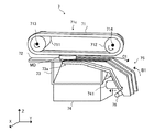
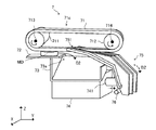
以下、図4、図5を参照して、本実施形態における振分装置について説明する。図4は、本実施形態における、開口が塞がれた状態の振分装置を示す斜視図である。図5は、本実施形態における、開口が露出した状態の振分装置を示す斜視図である。
=== Sorting device ===
Hereinafter, the sorting apparatus according to the present embodiment will be described with reference to FIGS. 4 and 5. FIG. 4 is a perspective view showing the sorting apparatus in a state in which the opening is closed in the present embodiment. FIG. 5 is a perspective view showing the sorting apparatus with the opening exposed in the present embodiment.
振分装置7は、メダルMDの搬送先を切り替える装置である。振分装置7は、ベルト装置63cによって正面側から背面側に搬送されてきたメダルMDの搬送先を、リフト5(図3)側又は搬送ベルト64側に切替える。振分装置7は、基台61及びベルト装置63cと、リフト5との間に設けられる。振分装置7は、ベルト装置71c、平板72、案内部材73、ソレノイド装置74、レバー75を有する。
The sorting device 7 is a device that switches the transport destination of the medal MD. The sorting device 7 switches the transport destination of the medal MD transported from the front side to the back side by the belt device 63c to the lift 5 (FIG. 3) side or the transport belt 64 side. The sorting device 7 is provided between the base 61 and the belt device 63 c and the lift 5. The sorting device 7 includes a belt device 71 c, a flat plate 72, a guide member 73, a solenoid device 74, and a lever 75.
平板72は、搬送ベルト63によって搬送されたメダルMDが載置される、例えば略矩形形状の部材である。平板72は、例えば、平板72上をメダルMDが滑って搬送されるように、メダルMDとの摩擦係数が比較的小さい材料によって形成される。平板72は、略水平とされた状態で、平板72の上面(+Z)の高さが基台61(図3)の上面の高さと同様となるように、筐体2内における基台61とリフト5との間に設けられる。尚、平板72は、平板72における正面側(−Y)の縁と、基台61の上面における背面側の縁との間の隙間から、メダルMDが落下しないように、基台61の近傍に設けられる。
The flat plate 72 is, for example, a substantially rectangular member on which the medal MD transported by the transport belt 63 is placed. The flat plate 72 is formed of, for example, a material having a relatively small friction coefficient with the medal MD so that the medal MD slides on the flat plate 72 and is conveyed. When the flat plate 72 is substantially horizontal, the height of the upper surface (+ Z) of the flat plate 72 is the same as the height of the upper surface of the base 61 (FIG. 3). It is provided between the lift 5. The flat plate 72 is located near the base 61 so that the medal MD does not fall from a gap between the front side (-Y) edge of the flat plate 72 and the back side edge of the upper surface of the base 61. Provided.
ベルト装置71cは、平板72上のメダルMDを正面側から背面側に搬送するための装置である。ベルト装置71cは、搬送ベルト71、ローラ711、712を有する。搬送ベルト71は、例えば、搬送ベルト62と同様な形状、材質のベルトである。搬送ベルト71は、ローラ711、712に掛け渡されている。ローラ711、712は、搬送ベルト71を支持すると共に、搬送ベルト71を動かすための回転ローラである。ローラ711、712のうち、何れか一方に、振分装置7を動作させるモータ(不図示)から回転駆動力が伝達される。ローラ711、712は夫々、X軸に沿った回転軸713、714を中心に、A1方向に回転する。ローラ711、712のうち、振分装置7を動作させるモータから回転駆動力が伝達される一方のローラが主プーリとして機能し、他方のローラが従プーリとして機能するので、ローラ711、712の回転速度は、相互に同様な回転速度となる。ローラ711、712は、平板72よりも上側に設けられる。ローラ711、712は、搬送ベルト71の下面が平板72の上面と対向した状態で略水平となるように、筐体2内に設けられる。ローラ711、712は、搬送ベルト71の下面と平板72の上面との間に挟まれたメダルMDが、搬送ベルト71の下面とメダルMDの上面との間の摩擦力によって、平板72上を正面側から背面側に滑って移動するように、設けられる。例えば、ローラ711、712が夫々、回転軸713、714を中心にA1方向に回転した場合、搬送ベルト71の下面は、正面側から背面側に移動することとなる。よって、平板72上のメダルMDは、搬送ベルト71の下面と平板72との間に挟まれた状態で、平板72上を滑るように正面側か背面側へ搬送される。
The belt device 71c is a device for transporting the medal MD on the flat plate 72 from the front side to the back side. The belt device 71 c includes a conveyance belt 71 and rollers 711 and 712. The conveyor belt 71 is, for example, a belt having the same shape and material as the conveyor belt 62. The conveyor belt 71 is stretched around rollers 711 and 712. The rollers 711 and 712 are rotating rollers for supporting the conveyor belt 71 and moving the conveyor belt 71. A rotational driving force is transmitted to one of the rollers 711 and 712 from a motor (not shown) that operates the sorting device 7. The rollers 711 and 712 rotate in the A1 direction around the rotation shafts 713 and 714 along the X axis, respectively. Of the rollers 711 and 712, one roller to which the rotational driving force is transmitted from the motor that operates the sorting device 7 functions as a main pulley, and the other roller functions as a sub pulley, so that the rotation of the rollers 711 and 712 The speeds are similar to each other. The rollers 711 and 712 are provided above the flat plate 72. The rollers 711 and 712 are provided in the housing 2 such that the lower surface of the transport belt 71 is substantially horizontal with the upper surface of the flat plate 72 facing the upper surface. The rollers 711 and 712 are arranged such that the medal MD sandwiched between the lower surface of the transport belt 71 and the upper surface of the flat plate 72 moves the front surface of the flat plate 72 forward by the frictional force between the lower surface of the transport belt 71 and the upper surface of the medal MD. It is provided so as to slide from the side to the back side. For example, when the rollers 711 and 712 rotate about the rotation shafts 713 and 714 in the A1 direction, the lower surface of the transport belt 71 moves from the front side to the back side. Therefore, the medal MD on the flat plate 72 is conveyed to the front side or the rear side so as to slide on the flat plate 72 while being sandwiched between the lower surface of the conveyance belt 71 and the flat plate 72.
レバー75は、メダルMDの搬送先を切り替えるための部材である。レバー75は、回転軸714と平行な回動軸76を中心に、B1方向(図4)又は、B2方向(図5)に回動できるように、筐体2内に設けられる。レバー75は、例えば、ソレノイド装置74が設けられる位置から、+X側から−X側へ向かって見た際に、上側且つ背面側に向かって抉られるような、略ク字形状を呈する。案内部材73の上側に設けられた開口73aを開閉できるように、レバー75の一方側は、上側から開口73aを覆うように、背面側から正面側に向かって突出するような形状を呈する。レバー75の上面は、レバー75の上面と搬送ベルト71の下面との間にメダルMDを挟んで、メダルMDを正面側から背面側へ搬送できるような平面形状を呈する。レバー75の一方側の端には、回動軸76を中心にレバー75をB2方向に回動した際に、レバー75の一方側の端と搬送ベルト71とが干渉しないように溝751が形成されている。レバー75の一方側とは反対側の他方側の下部には、回動軸76が取り付けられる。
The lever 75 is a member for switching the transport destination of the medal MD. The lever 75 is provided in the housing 2 so as to be able to rotate in the B1 direction (FIG. 4) or the B2 direction (FIG. 5) around a rotation shaft 76 parallel to the rotation shaft 714. The lever 75 has, for example, a substantially K-shape that is squeezed toward the upper side and the back side when viewed from the + X side to the −X side from the position where the solenoid device 74 is provided. In order to be able to open and close the opening 73a provided on the upper side of the guide member 73, one side of the lever 75 has a shape protruding from the back side toward the front side so as to cover the opening 73a. The upper surface of the lever 75 has a planar shape that allows the medal MD to be conveyed from the front side to the back side with the medal MD sandwiched between the upper surface of the lever 75 and the lower surface of the conveyance belt 71. A groove 751 is formed at one end of the lever 75 so that the one end of the lever 75 and the transport belt 71 do not interfere when the lever 75 is rotated in the B2 direction around the rotation shaft 76. Has been. A rotation shaft 76 is attached to the lower part of the other side opposite to the one side of the lever 75.
ソレノイド装置74は、レバー75を回動させるための装置である。ソレノイド装置74は、レバー75における背面側かつ上側に向かって抉られている位置に配設される。ソレノイド装置74における可動部材741の先端は、例えば、レバー75の他方側における回動軸76が取り付けられている位置よりも上側の位置に正面側から接続される。可動部材741は、Y軸に沿って背面側に移動したり、正面側に移動したりする、例えば棒状の部材である。可動部材741の移動は、制御装置9によって制御される。例えば、制御装置9から出力される落下信号を受信したとき、ソレノイド装置74内のソレノイド(不図示)が通電されることとする。そのとき、ソレノイド装置74は、可動部材741を背面側に移動させることとする。又、例えば、制御装置9から出力される通過信号を受信した場合、ソレノイド装置74内のソレノイドに供給される電流は遮断されることとする。そのとき、ソレノイド装置74は、可動部材741を正面側に移動させることとする。
The solenoid device 74 is a device for rotating the lever 75. The solenoid device 74 is disposed at a position where the lever 75 is beaten toward the rear side and the upper side. For example, the tip of the movable member 741 in the solenoid device 74 is connected from the front side to a position above the position where the rotation shaft 76 is attached on the other side of the lever 75. The movable member 741 is, for example, a rod-shaped member that moves to the back side along the Y axis or moves to the front side. The movement of the movable member 741 is controlled by the control device 9. For example, when a fall signal output from the control device 9 is received, a solenoid (not shown) in the solenoid device 74 is energized. At that time, the solenoid device 74 moves the movable member 741 to the back side. Further, for example, when a passage signal output from the control device 9 is received, the current supplied to the solenoid in the solenoid device 74 is cut off. At that time, the solenoid device 74 moves the movable member 741 to the front side.
案内部材73は、メダルMDが開口73aから、ソレノイド装置74を避けて落下するように、メダルMDを案内するための部材である。尚、開口73aから落下したメダルMDは、搬送ベルト64の上面に載置されることとなる。
The guide member 73 is a member for guiding the medal MD so that the medal MD falls from the opening 73a while avoiding the solenoid device 74. Note that the medal MD dropped from the opening 73 a is placed on the upper surface of the transport belt 64.
例えば、可動部材741が背面側から正面側に向かって移動した場合、レバー75は、回動軸76を中心にB1方向に回動して、レバー75の一方側によって開口73aが塞がれることとなる。このとき、平板72上のメダルMDは、レバー75上をC1方向(図4)へ搬送されることとなる。C1方向に搬送されたメダルMDは、リフト5のシュータ(不図示)に投入されることとなる。尚、シュータとして、例えば、特開平4−86981号公報に開示されている技術を採用することが可能である。一方、例えば、可動部材741が正面側から背面側に向かって移動した場合、レバー75は、回動軸76を中心にB2方向に回動して、開口73aが露出した状態となる。このとき、平板72上のメダルMDは、C2方向(図5)へ落下することとなる。C2方向に落下したメダルMDは、搬送ベルト64の上面に載置されることとなる。
For example, when the movable member 741 moves from the back side toward the front side, the lever 75 rotates in the B1 direction around the rotation shaft 76, and the opening 73a is blocked by one side of the lever 75. It becomes. At this time, the medal MD on the flat plate 72 is conveyed on the lever 75 in the C1 direction (FIG. 4). The medals MD transported in the C1 direction are put into a shooter (not shown) of the lift 5. As a shooter, for example, a technique disclosed in Japanese Patent Laid-Open No. 4-86981 can be adopted. On the other hand, for example, when the movable member 741 moves from the front side toward the back side, the lever 75 rotates about the rotation shaft 76 in the B2 direction so that the opening 73a is exposed. At this time, the medal MD on the flat plate 72 falls in the C2 direction (FIG. 5). The medal MD dropped in the C2 direction is placed on the upper surface of the transport belt 64.
===リフト===
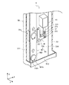
以下、図3、図6を参照して、本実施形態におけるリフトについて説明する。図6は、本実施形態における、リフトの内部を示す斜視図である。尚、図6は、筐体50の一部が省略された状態を示している。
=== Lift ===
Hereinafter, the lift in the present embodiment will be described with reference to FIGS. 3 and 6. FIG. 6 is a perspective view showing the inside of the lift in the present embodiment. FIG. 6 shows a state in which a part of the housing 50 is omitted.
リフト5は、筐体2内に投入されたメダルMDを、下側(−Z)から上側(+Z)に搬送する装置である。リフト5は、シュータ内に投入されたメダルMDを、開口51aから排出したり、開口51bから排出したりする。リフト5は、筐体50、搬送ベルト58、ローラ581、582、振分装置59を有する。尚、振分装置59については、後述する。
The lift 5 is a device that conveys the medal MD inserted into the housing 2 from the lower side (−Z) to the upper side (+ Z). The lift 5 discharges the medal MD inserted into the shooter from the opening 51a or from the opening 51b. The lift 5 includes a housing 50, a conveyance belt 58, rollers 581 and 582, and a sorting device 59. The distribution device 59 will be described later.
筐体50は、例えば、略矩形柱形状を呈する。筐体50は、内部に搬送ベルト58、ローラ581、582、振分装置59を収容できるように、中空構造となっている。筐体50の垂直方向(Z軸)の長さは、シュータ内に投入されたメダルMDをホッパ202よりも上側まで搬送できる搬送ベルト58が内部に配設されるように、例えば、基台61の上面からホッパ202の上側の縁までの垂直方向の長さよりも長いものとする。筐体50は、計数ユニット203(図2)及びホッパ202と、背面板2cとの間に設けられる。筐体50は、筐体50の正面板511が振分装置7、ベルト装置65c、ホッパ202と対向するように、筐体2内に設けられる。筐体50は、筐体50の上部がホッパ202の上側の縁よりも上側に突出するように設けられる。筐体50の正面板511におけるホッパ202の上側の縁よりも高い位置には、リフト5によって下側から上側に搬送されるメダルMDをリフト5の筐体50から排出するための開口51a(図2)が形成される。正面板511における、開口51aが形成される位置よりも低く、且つ、搬送ベルト65の上面の高さよりも高い位置には、リフト5に下側から上側に搬送されるメダルMDを筐体50から排出するための開口51bが形成される。
The housing 50 has, for example, a substantially rectangular column shape. The housing 50 has a hollow structure so that the conveyance belt 58, rollers 581 and 582, and the sorting device 59 can be accommodated therein. The length of the casing 50 in the vertical direction (Z-axis) is, for example, the base 61 so that the transport belt 58 that can transport the medal MD inserted into the shooter to the upper side of the hopper 202 is disposed inside. It is assumed that it is longer than the vertical length from the upper surface of the hopper 202 to the upper edge of the hopper 202. The casing 50 is provided between the counting unit 203 (FIG. 2) and the hopper 202, and the back plate 2c. The housing 50 is provided in the housing 2 so that the front plate 511 of the housing 50 faces the sorting device 7, the belt device 65 c, and the hopper 202. The housing 50 is provided such that the upper portion of the housing 50 protrudes above the upper edge of the hopper 202. At a position higher than the upper edge of the hopper 202 in the front plate 511 of the housing 50, an opening 51 a (see FIG. 5) for discharging the medal MD conveyed from the lower side to the upper side by the lift 5 from the housing 50 of the lift 5. 2) is formed. At a position lower than the position where the opening 51a is formed on the front plate 511 and higher than the height of the upper surface of the transport belt 65, the medal MD transported from the lower side to the upper side by the lift 5 is removed from the housing 50. An opening 51b for discharging is formed.
搬送ベルト58は、例えば、表面にゴム等を被覆して、メダルMDとの摩擦係数が比較的大きくなるように形成された平ベルトである。搬送ベルト58は、ローラ581、582に掛け渡されている。ローラ581、582は、搬送ベルト58を支持すると共に、搬送ベルト58を動かすための回転ローラである。ローラ581、582のうち、何れか一方に、リフト5を動作させるモータ(不図示)から回転駆動力が伝達される。ローラ581は、ローラ581の中心におけるY軸に沿った回転軸(以下、「ローラ581の回転軸」と称する)を中心に、−Y方向から+Y方向に向かって見て反時計回り方向(以下、「D1方向」と称する)に回転する。ローラ582は、ローラ582の中心におけるY軸に沿った回転軸(以下、「ローラ582の回転軸」と称する)を中心に、D1方向に回転する。ローラ581、582のうち、リフト5を動作させるモータから回転駆動力が伝達される一方のローラが主プーリとして機能し、他方のローラが従プーリとして機能するので、ローラ581、582の回転速度は、相互に同様な回転速度となる。尚、リフト5を動作させるモータの起動及び停止は、例えば、制御装置9によって制御されるものとする。ローラ581、582は、搬送ベルト58の一方側(+X)の面によってメダルMDが下側から上側に搬送されるように、搬送ベルト58の一方側の面が略垂直な状態で、側面板512の他方側の面と対向するように、筐体50内に設けられる。尚、搬送ベルト58の長手方向の長さは、搬送ベルト58の一方側の面における垂直方向の長さが、基台61の上面からホッパ202の上側の縁までの垂直方向の長さよりも長くなるように、設定される。ローラ581、582は、搬送ベルト58の一方側の面と側面板512の他方側の面との間の隙間のX軸方向の幅が、メダルMDの1枚分の厚さよりも長く、且つ、メダルMDの2枚分の厚さよりも短くなるように、設けられる。ローラ581は、ホッパ202の上側の縁よりも上側に設けられる。ローラ582は、例えば、振分装置7と同様な高さの位置に設けられる。
The conveyor belt 58 is, for example, a flat belt formed by covering the surface with rubber or the like so that the friction coefficient with the medal MD is relatively large. The conveyor belt 58 is stretched around rollers 581 and 582. The rollers 581 and 582 are rotating rollers for supporting the conveyor belt 58 and for moving the conveyor belt 58. A rotational driving force is transmitted to one of the rollers 581 and 582 from a motor (not shown) that operates the lift 5. The roller 581 is centered on a rotation axis along the Y axis at the center of the roller 581 (hereinafter referred to as “rotation axis of the roller 581”), and is counterclockwise when viewed from the −Y direction toward the + Y direction (hereinafter referred to as “rotation axis”). , Referred to as “D1 direction”). The roller 582 rotates in the direction D1 about a rotation axis along the Y axis at the center of the roller 582 (hereinafter referred to as “rotation axis of the roller 582”). Of the rollers 581 and 582, one roller to which the rotational driving force is transmitted from the motor that operates the lift 5 functions as a main pulley, and the other roller functions as a sub pulley, so the rotational speed of the rollers 581 and 582 is , The rotational speed is similar to each other. In addition, the starting and stop of the motor which operates the lift 5 shall be controlled by the control apparatus 9, for example. The rollers 581 and 582 are configured so that the side plate 512 is in a state where the surface on one side of the transport belt 58 is substantially vertical so that the medal MD is transported from the lower side to the upper side by the one side (+ X) surface of the transport belt 58. It is provided in the housing 50 so as to face the other side surface. The length in the longitudinal direction of the transport belt 58 is such that the length in the vertical direction on one surface of the transport belt 58 is longer than the length in the vertical direction from the upper surface of the base 61 to the upper edge of the hopper 202. To be set. The rollers 581 and 582 are such that the width in the X-axis direction of the gap between one surface of the conveyor belt 58 and the other surface of the side plate 512 is longer than the thickness of one medal MD, and It is provided so as to be shorter than the thickness of two medals MD. The roller 581 is provided above the upper edge of the hopper 202. The roller 582 is provided, for example, at the same height as the sorting device 7.
ローラ581、582に掛け渡されている搬送ベルト58の外側の面には、メダルMDが載置される突起581b、582bが設けられる。突起581b、582bは、対となってメダルMDを下側から支持できるように、搬送ベルト58の外側の面における相互に同じ高さの位置に設けられる。尚、振分装置7でC1方向に振分られたメダルMDは、リフト5のシュータ内で1枚ずつ整列されて、搬送ベルト58の一方側の面における下側の縁で、突起581b、582b上に1枚ずつ載置されることとする。突起581b、582bの対は、複数のメダルMDを同時に下側から上側に搬送できるように、搬送ベルト58の外側の面に搬送ベルト58の長手方向に沿って複数設けられる。尚、突起581b、582bのX軸方向の長さは、搬送ベルト58の一方側の面が上側に向かって移動したときに、側面板512における他方側の面と接触しない程度に設定される。尚、搬送ベルト58の一方側の面における上側の縁と、側面板512における他方側の面との間には、搬送ベルト58によって下側から上側に向かって搬送されるメダルMDを、開口51aへ案内するための案内部材(不図示)が設けられているものとする。
Protrusions 581b and 582b on which medals MD are placed are provided on the outer surface of the conveyor belt 58 that is stretched over the rollers 581 and 582. The protrusions 581b and 582b are provided at the same height on the outer surface of the conveyance belt 58 so that the medals MD can be supported from the lower side as a pair. The medals MD distributed in the C1 direction by the distribution device 7 are aligned one by one in the shooter of the lift 5, and the protrusions 581b and 582b are formed at the lower edge of one surface of the conveyor belt 58. One piece is placed on the top. A plurality of pairs of protrusions 581b and 582b are provided on the outer surface of the conveyor belt 58 along the longitudinal direction of the conveyor belt 58 so that a plurality of medals MD can be simultaneously conveyed from the lower side to the upper side. Note that the lengths of the protrusions 581b and 582b in the X-axis direction are set to such an extent that the one side surface of the conveyor belt 58 does not come into contact with the other side surface of the side plate 512. Note that a medal MD conveyed from the lower side to the upper side by the conveying belt 58 is opened between the upper edge of the one side surface of the conveying belt 58 and the other side surface of the side plate 512 by an opening 51a. It is assumed that a guide member (not shown) for guiding to is provided.
例えば、ローラ581、582が夫々、ローラ581の回転軸、ローラ582の回転軸を中心にD1方向に回転した場合、搬送ベルト58の一方側の面は、下側から上側に移動することとなる。突起581b、582b上に載置されているメダルMDは、搬送ベルト58の一方側の面と側面板512の他方側の面との間を、下側から上側に向かって移動することとなる。その後、当該メダルMDは、案内部材によって開口51aから排出された後、ホッパ202内に貯留されることとなる。尚、例えば、側面板512の他方側の面は、下側から上側に向かって移動するメダルMDが側面板512の他方側の面と接触した際に、メダルMDが受ける摩擦力が弱くなるように、メダルMDとの摩擦係数が比較的小さい材料を用いて形成されることとしてもよい。
For example, when the rollers 581 and 582 rotate in the D1 direction around the rotation axis of the roller 581 and the rotation axis of the roller 582, the surface on one side of the conveyance belt 58 moves from the lower side to the upper side. . The medal MD placed on the protrusions 581b and 582b moves from the lower side to the upper side between the one side surface of the conveyor belt 58 and the other side surface of the side plate 512. Thereafter, the medal MD is stored in the hopper 202 after being discharged from the opening 51a by the guide member. For example, when the medal MD moving from the lower side toward the upper side comes into contact with the other side surface of the side plate 512, the other side surface of the side plate 512 has a weak frictional force applied to the medal MD. Furthermore, it is good also as forming using the material whose friction coefficient with medal MD is comparatively small.
===リフトの振分装置===
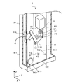
以下、図3、図6、図7を参照して、本実施形態におけるリフトの振分装置について説明する。図7は、本実施形態における、メダルを開口へ案内している状態のリフトの内部を示す斜視図である。尚、図7は、筐体50の一部が省略された状態を示している。
=== Lift distribution device ===
Hereinafter, with reference to FIGS. 3, 6, and 7, the lift distributing apparatus according to the present embodiment will be described. FIG. 7 is a perspective view showing the inside of the lift in the state where the medal is guided to the opening in the present embodiment. FIG. 7 shows a state in which a part of the housing 50 is omitted.
振分装置59は、メダルMDの搬送先を切り替える装置である。振分装置59は、リフト5によって下側から上側に向かって搬送されるメダルMDの搬送先を、開口51a側又は開口51b側に切替える。振分装置59は、筐体50内における開口51bと同様な高さの位置に設けられる。振分装置59は、ソレノイド装置55、レバー56、リンク部材57を有する。
The sorting device 59 is a device that switches the transport destination of the medal MD. The sorting device 59 switches the transport destination of the medal MD transported from the lower side to the upper side by the lift 5 to the opening 51a side or the opening 51b side. The sorting device 59 is provided at the same height as the opening 51 b in the housing 50. The sorting device 59 includes a solenoid device 55, a lever 56, and a link member 57.
レバー56は、ソレノイド装置55から供給される駆動力に応じて、メダルMDの搬送先を切り替えるための部材である。レバー56は、一方側(+X)から他方側(−X)に向かって見て、略L字形状を呈する板部材である。レバー56は、搬送ベルト58の一方側の面と平行となるように、筐体50内に設けられる。レバー56は、レバー56における2辺を形成する部材が交わる位置においてX軸方向に沿った回動軸561を中心に、E1方向(図6)又はE2方向(図7)へ回動できるように、取付部材562によって筐体50の側面板514の一方側の面に取り付けられる。レバー56は、レバー56が回動軸561を中心にE2方向に回動した際に、レバー56の一方の辺を形成する部材(以下、「一方の部材」と称する)が、搬送ベルト58の一方側の面と側面板512との間の隙間に挿入されるように、搬送ベルト58の近傍に取り付けられる。尚、レバー56の厚さは、搬送ベルト58の一方側の面と、側面板512との間の隙間のX軸方向の幅よりも薄いものとする。
The lever 56 is a member for switching the transport destination of the medal MD according to the driving force supplied from the solenoid device 55. The lever 56 is a plate member having a substantially L shape when viewed from one side (+ X) to the other side (−X). The lever 56 is provided in the housing 50 so as to be parallel to the surface on one side of the transport belt 58. The lever 56 can be rotated in the E1 direction (FIG. 6) or the E2 direction (FIG. 7) around the rotation shaft 561 along the X-axis direction at a position where members forming two sides of the lever 56 intersect. The mounting member 562 is attached to one surface of the side plate 514 of the housing 50. The lever 56 is a member that forms one side of the lever 56 (hereinafter referred to as “one member”) when the lever 56 rotates in the E2 direction around the rotation shaft 561. It is attached in the vicinity of the conveyor belt 58 so as to be inserted into the gap between the one side surface and the side plate 512. Note that the thickness of the lever 56 is thinner than the width in the X-axis direction of the gap between the one side surface of the conveyor belt 58 and the side plate 512.
ソレノイド装置55は、レバー56を回動させるための装置である。ソレノイド装置55は、レバー56の他方の辺を形成する部材(以下、「他方の部材」と称する)の上側(+Z)からレバー56に対して駆動力を与えるように、他方の部材の上側に取り付けられる。ソレノイド装置55は、可動部材551を有する。可動部材551は、垂直方向(Z軸)に沿って上側に移動したり、下側(−Z)に移動したりする、棒状の部材である。可動部材551の移動は、制御装置9によって制御される。
The solenoid device 55 is a device for rotating the lever 56. The solenoid device 55 is arranged on the upper side of the other member so as to apply a driving force to the lever 56 from the upper side (+ Z) of the member forming the other side of the lever 56 (hereinafter referred to as “the other member”). It is attached. The solenoid device 55 has a movable member 551. The movable member 551 is a rod-shaped member that moves upward along the vertical direction (Z-axis) or moves downward (−Z). The movement of the movable member 551 is controlled by the control device 9.
例えば、制御装置9から出力される真信号を受信したとき、ソレノイド装置55内のソレノイド(不図示)が通電されることとする。そのとき、ソレノイド装置55は、可動部材551を下側に移動させることとする。又、例えば、制御装置9から出力される偽信号を受信した場合、ソレノイド装置55内のソレノイドに供給される電流は遮断されることとする。そのとき、ソレノイド装置55は、可動部材551を上側に移動させることとする。
For example, when a true signal output from the control device 9 is received, a solenoid (not shown) in the solenoid device 55 is energized. At that time, the solenoid device 55 moves the movable member 551 downward. For example, when a false signal output from the control device 9 is received, the current supplied to the solenoid in the solenoid device 55 is cut off. At that time, the solenoid device 55 moves the movable member 551 upward.
可動部材551の先端は、リンク部材57を介してレバー56における他方の部材の背面側の端部と連結される。尚、リンク部材57の一端は、X軸に沿った回動軸571を中心に回動できるように、可動部材551の先端に回動自在に取り付けられる。リンク部材57の他端は、X軸に沿った回動軸572を中心に回動できるように、レバー56における他方の部材の背面側の端部に回動自在に取り付けられる。
The distal end of the movable member 551 is connected to the rear end portion of the other member of the lever 56 via the link member 57. Note that one end of the link member 57 is rotatably attached to the distal end of the movable member 551 so that the end of the link member 57 can rotate about a rotation shaft 571 along the X axis. The other end of the link member 57 is rotatably attached to an end portion on the back side of the other member in the lever 56 so that the other end of the link member 57 can be rotated around a rotation shaft 572 along the X axis.
例えば、可動部材551が上側から下側に向かって移動した場合、レバー56は、回動軸561を中心にE1方向に回動して、レバー56の一方の部材が搬送ベルト58の一方側の面と側面板512との間から外れた位置に移動する。このとき、メダルMDは、突起581b、582bに載置された状態で下側から上側へ搬送される。その後、当該メダルMDは、開口51aから排出されて、ホッパ202内に貯留されることとなる。一方、例えば、可動部材551が下側から上側に向かって移動した場合、レバー56は、回動軸561を中心にE2方向に回動して、レバー56における一方の部材の上側の端部が搬送ベルト58の一方側の面と側面板512との間に移動する。このとき、突起581b、582bに載置された状態で搬送ベルト58に下側から上側に向かって搬送されているメダルMDが、レバー56の一方の部材における下側の縁と当接して、開口51bから筐体50外へ排出される。当該メダルMDは、案内板51cによって搬送ベルト65の上面に案内されることとなる。
For example, when the movable member 551 moves from the upper side to the lower side, the lever 56 rotates in the E1 direction around the rotation shaft 561 so that one member of the lever 56 is on one side of the transport belt 58. It moves to a position deviated from between the surface and the side plate 512. At this time, the medal MD is conveyed from the lower side to the upper side while being placed on the protrusions 581b and 582b. Thereafter, the medal MD is discharged from the opening 51 a and stored in the hopper 202. On the other hand, for example, when the movable member 551 moves from the lower side toward the upper side, the lever 56 rotates in the E2 direction around the rotation shaft 561, and the upper end portion of one member of the lever 56 moves. It moves between one side surface of the conveyor belt 58 and the side plate 512. At this time, the medal MD transported from the lower side to the upper side by the transport belt 58 in a state of being placed on the protrusions 581b and 582b comes into contact with the lower edge of one member of the lever 56, and is opened. 51b is discharged out of the housing 50. The medal MD is guided to the upper surface of the conveyor belt 65 by the guide plate 51c.
尚、基台61、ベルト装置63c、振分装置7、リフト5、案内板51c、ベルト装置65c、傾斜板13が、第1搬送装置に相当する。基台61、ベルト装置63c、振分装置7、リフト5が第2搬送装置に相当する。基台61、ベルト装置62c、振分装置7、リフト5における下端から開口51bが形成されている位置までの一部が、第1搬送部に相当する。振分装置59、案内板51c、ベルト装置65c、傾斜板13が第2搬送部に相当する。振分装置59、リフト5における開口51bが形成されている位置から上端までの一部が、第3搬送部に相当する。振分装置7、ベルト装置64cが第3搬送装置に相当する。
The base 61, the belt device 63c, the sorting device 7, the lift 5, the guide plate 51c, the belt device 65c, and the inclined plate 13 correspond to the first transport device. The base 61, the belt device 63c, the sorting device 7, and the lift 5 correspond to the second transport device. A part from the lower end of the base 61, the belt device 62c, the sorting device 7, and the lift 5 to the position where the opening 51b is formed corresponds to the first transport unit. The distribution device 59, the guide plate 51c, the belt device 65c, and the inclined plate 13 correspond to the second transport unit. The part from the position where the opening 51b in the sorting device 59 and the lift 5 is formed to the upper end corresponds to the third transport unit. The sorting device 7 and the belt device 64c correspond to a third transport device.
===ホッパ===
以下、図3を参照して、本実施形態におけるホッパについて説明する。
ホッパ202は、内部に貸し出し用のメダルMDが貯留される容器である。ホッパ202は、ベルト装置65c及び開口25aよりも上側(+Z)に設けられる。ホッパ202は、電極141乃至143、メダル排出口11、第1導通センサ(不図示)、第2導通センサ(不図示)を有する。尚、電極143、141、第2導通センサが検出装置に相当する。
=== Hopper ===
Hereinafter, with reference to FIG. 3, the hopper in this embodiment is demonstrated.
The hopper 202 is a container in which lent medals MD are stored. The hopper 202 is provided above (+ Z) the belt device 65c and the opening 25a. The hopper 202 includes electrodes 141 to 143, a medal discharge port 11, a first conduction sensor (not shown), and a second conduction sensor (not shown). The electrodes 143 and 141 and the second continuity sensor correspond to the detection device.
メダル排出口11は、ホッパ202内に貯留されているメダルMDを排出するための孔である。例えば、ビルバリに金銭が投入された後、タッチパネル22上に表示された貸出釦が押下された場合、ビルバリに投入された金銭に基づく枚数のメダルMDが、メダル排出口11から排出される。当該メダルMDは、傾斜板12上を流下して開口25aから筐体2外へ排出されることとなる。
The medal discharge port 11 is a hole for discharging the medal MD stored in the hopper 202. For example, when a lending button displayed on the touch panel 22 is pressed after money is inserted into the bill burr, the number of medals MD based on the money thrown into the bill burr is discharged from the medal discharge port 11. The medal MD flows down on the inclined plate 12 and is discharged out of the housing 2 through the opening 25a.
ここで、傾斜板12は、例えば略矩形形状を呈する平板である。傾斜板12は、ホッパ202内のメダルMDと、ベルト装置65cによって搬送されてきたメダルMDとを夫々、開口25a、25bから排出するために、メダルMDの搬送路を区画する区画板として機能する。傾斜板12は、ホッパ202内のメダルMDが開口25aから排出されるように、傾斜板13の上側に設けられる。傾斜板12は、傾斜板12の正面側(−Y)の縁の高さが、傾斜板12の背面側(+Y)の縁の高さよりも低くなるように、筐体2内に配設される。よって、ホッパ202から排出されたメダルMDは、傾斜板12上を流下して開口25aから排出される。又、ベルト装置65cによって搬送されてきたメダルMDは、傾斜板13を介して開口25bから排出される。つまり、ホッパ202内のメダルMDと、ベルト装置65cによって搬送されてきたメダルMDとが夫々、別の開口25a、25bから排出されることとなる。
Here, the inclined plate 12 is a flat plate having a substantially rectangular shape, for example. The inclined plate 12 functions as a partition plate for partitioning the transport path of the medal MD in order to discharge the medal MD in the hopper 202 and the medal MD transported by the belt device 65c from the openings 25a and 25b, respectively. . The inclined plate 12 is provided on the upper side of the inclined plate 13 so that the medals MD in the hopper 202 are discharged from the opening 25a. The inclined plate 12 is disposed in the housing 2 such that the height of the edge on the front side (−Y) of the inclined plate 12 is lower than the height of the edge on the back side (+ Y) of the inclined plate 12. The Therefore, the medal MD discharged from the hopper 202 flows down on the inclined plate 12 and is discharged from the opening 25a. The medal MD conveyed by the belt device 65c is discharged from the opening 25b through the inclined plate 13. That is, the medal MD in the hopper 202 and the medal MD conveyed by the belt device 65c are discharged from the separate openings 25a and 25b, respectively.
電極141乃至143は、ホッパ202内のメダルMDの量(以下、「ホッパ202内のメダル量」と称する)を検出するためにホッパ202内に設けられる。電極143、142は、対となって、ホッパ202内のメダル量が第1メダル量を下回ったことを検出ためのエンド検知センサとして機能する。第1メダル量とは、例えば、ビルバリに投入された金銭に基づくメダルMDの枚数を台間機200から貸し出せない虞がある程度のメダルMDの量である。電極143、141は、対となって、ホッパ202内のメダル量が第2メダル量(所定量)を下回ったことを検出ためのニアエンド検知センサとして機能する。第2メダル量とは、例えば、予め決められているホッパ202の最大のメダル貯留容量よりも少なく、且つ、第1メダル量よりも多い、ホッパ202内のメダル量である。第2メダル量は、例えば、ホッパ202内にメダルMDを補給するか否かの判断のために用いられる。尚、メダルMDの補給については、後述する。
The electrodes 141 to 143 are provided in the hopper 202 in order to detect the amount of medals MD in the hopper 202 (hereinafter referred to as “medal amount in the hopper 202”). The electrodes 143 and 142 function as a pair and function as an end detection sensor for detecting that the medal amount in the hopper 202 is less than the first medal amount. The first medal amount is, for example, the medal MD amount to a certain degree that there is a possibility that the number of medals MD based on money inserted into the bill burr cannot be lent out from the inter-machine 200. The electrodes 143 and 141 function as a pair and function as a near-end detection sensor for detecting that the medal amount in the hopper 202 has fallen below the second medal amount (predetermined amount). The second medal amount is, for example, a medal amount in the hopper 202 that is smaller than a predetermined maximum medal storage capacity of the hopper 202 and larger than the first medal amount. The second medal amount is used, for example, for determining whether or not to supply the medal MD into the hopper 202. The replenishment of medals MD will be described later.
電極143は、例えば、メダル排出口11と同程度の高さの位置において略水平に配設される金属製の棒部材である。
The electrode 143 is, for example, a metal bar member that is disposed substantially horizontally at a height approximately the same as that of the medal discharge port 11.
電極142は、例えば、背面側から正面側に向かうにつれて高さが低くなるように傾斜する金属製の板部材である。電極142の背面側の縁は、ホッパ202の背面側の内壁における上側の縁の近傍に取り付けられる。電極142の正面側の縁は、ホッパ202の略中央に向かって突出している。尚、電極142の正面側の縁の高さは、ホッパ202内のメダル量が第1メダル量より多いときに、電極142の正面側の縁とホッパ202内のメダルMDとが接触し、且つ、ホッパ202内のメダル量が第1メダル量より少ないときに、電極142の正面側の縁とホッパ202内のメダルMDとが接触しないような高さに設定される。つまり、ホッパ202内のメダル量が第1メダル量よりも少ない場合、電極142とホッパ202内のメダルMDとは接触しない状態となり、ホッパ202内のメダル量が第1メダル量に達したときに、電極142とホッパ202内のメダルMDとが接触することとなる。尚、電極142の正面側の縁の高さは、メダル排出口11の高さよりも高く設定される。
The electrode 142 is, for example, a metal plate member that is inclined so that the height decreases from the back side toward the front side. The back side edge of the electrode 142 is attached in the vicinity of the upper side edge of the back side inner wall of the hopper 202. The front edge of the electrode 142 protrudes toward the approximate center of the hopper 202. The height of the front edge of the electrode 142 is such that the front edge of the electrode 142 and the medal MD in the hopper 202 are in contact with each other when the amount of medals in the hopper 202 is larger than the first medal amount. When the medal amount in the hopper 202 is smaller than the first medal amount, the height is set such that the front edge of the electrode 142 and the medal MD in the hopper 202 do not contact each other. That is, when the medal amount in the hopper 202 is smaller than the first medal amount, the electrode 142 and the medal MD in the hopper 202 are not in contact with each other, and the medal amount in the hopper 202 reaches the first medal amount. The electrode 142 and the medal MD in the hopper 202 come into contact with each other. The height of the front edge of the electrode 142 is set higher than the height of the medal discharge port 11.
電極141は、例えば、正面側から背面側に向かうにつれて高さが低くなるように傾斜する金属製の板部材である。電極141の正面側の縁は、ホッパ202の正面側の内壁における電極142の背面側の縁と同様な高さの位置に取り付けられる。電極141の背面側の縁は、ホッパ202の略中央に向かって突出している。尚、電極141は、電極141の背面側の縁の高さが、電極板142の正面側の縁の高さよりも高くなるように、ホッパ202内に取り付けられる。電極141背面側の縁の高さは、ホッパ202内のメダル量が第2メダル量より多いときに、電極141の背面側の縁とホッパ202内のメダルMDとが接触し、且つ、ホッパ202内のメダル量が第2メダル量より少ないときに、電極141の背面側の縁とホッパ202内のメダルMDとが接触しないような高さに設定される。つまり、ホッパ202内のメダル量が第2メダル量よりも少ない場合、電極141とホッパ202内のメダルMDとは接触しない状態となり、ホッパ202内のメダル量が第2メダル量に達したときに、電極141とホッパ202内のメダルMDとが接触することとなる。
The electrode 141 is, for example, a metal plate member that is inclined so that the height decreases from the front side toward the back side. The edge on the front side of the electrode 141 is attached to the same height as the edge on the back side of the electrode 142 on the inner wall on the front side of the hopper 202. An edge on the back side of the electrode 141 protrudes toward the approximate center of the hopper 202. The electrode 141 is mounted in the hopper 202 such that the height of the edge on the back side of the electrode 141 is higher than the height of the edge on the front side of the electrode plate 142. The height of the edge on the back side of the electrode 141 is such that when the amount of medals in the hopper 202 is larger than the second amount of medals, the edge on the back side of the electrode 141 and the medal MD in the hopper 202 come into contact with each other. When the inner medal amount is smaller than the second medal amount, the height is set such that the rear edge of the electrode 141 does not contact the medal MD in the hopper 202. That is, when the medal amount in the hopper 202 is smaller than the second medal amount, the electrode 141 and the medal MD in the hopper 202 are not in contact with each other, and the medal amount in the hopper 202 reaches the second medal amount. The electrode 141 and the medal MD in the hopper 202 come into contact with each other.
第1導通センサは、電極143と電極142とが電気的に接続されているか否かを検出するための装置である。例えば、ホッパ202内のメダルMDが第1メダル量よりも少ない場合、電極142はホッパ202内のメダルMDと接触しないこととなる。電極143と電極142とは、電気的に遮断されることとなる。このとき、第1導通センサは、第1検出信号を出力するものとする。一方、例えば、ホッパ202内のメダルMDが第1メダル量に達したとき、電極142はホッパ202内のメダルMDと接触することとなる。電極143と電極142は、電気的に接続されることとなる。このとき、第1導通センサは、第1検出信号を出力しないものとする。
The first continuity sensor is a device for detecting whether or not the electrode 143 and the electrode 142 are electrically connected. For example, when the medal MD in the hopper 202 is smaller than the first medal amount, the electrode 142 does not contact the medal MD in the hopper 202. The electrode 143 and the electrode 142 are electrically cut off. At this time, the first continuity sensor outputs a first detection signal. On the other hand, for example, when the medal MD in the hopper 202 reaches the first medal amount, the electrode 142 comes into contact with the medal MD in the hopper 202. The electrode 143 and the electrode 142 are electrically connected. At this time, the first continuity sensor does not output the first detection signal.
第2導通センサは、電極143と電極141とが電気的に接続されているか否かを検出するための装置である。例えば、ホッパ202内のメダルMDが第2メダル量よりも少ない場合、電極141はホッパ202内のメダルMDと接触しないこととなる。電極143と電極141とは、電気的に遮断されることとなる。このとき、第2導通センサは、第2検出信号を出力するものとする。一方、例えば、ホッパ202内のメダルMDが第2メダル量に達したとき、電極141はホッパ202内のメダルMDと接触することとなる。電極143と電極141は、電気的に接続されることとなる。このとき、第2導通センサは、第2検出信号を出力しないものとする。
The second continuity sensor is a device for detecting whether or not the electrode 143 and the electrode 141 are electrically connected. For example, when the medal MD in the hopper 202 is smaller than the second medal amount, the electrode 141 does not contact the medal MD in the hopper 202. The electrode 143 and the electrode 141 are electrically cut off. At this time, the second continuity sensor outputs a second detection signal. On the other hand, for example, when the medal MD in the hopper 202 reaches the second medal amount, the electrode 141 comes into contact with the medal MD in the hopper 202. The electrode 143 and the electrode 141 are electrically connected. At this time, the second continuity sensor does not output the second detection signal.
===メダルMDの補給===
以下、図3を参照して、本実施形態におけるメダルMDの補給について説明する。
ホッパ202内へのメダルMDの補給は、メダル補給装置(不図示)によって自動的に行われたり、遊技機100が設置されている遊技場内のホールスタッフ(不図示)によって手動で行われたりする。
=== Replenishment of medal MD ===
Hereinafter, with reference to FIG. 3, the replenishment of medals MD in the present embodiment will be described.
The replenishment of the medal MD into the hopper 202 is automatically performed by a medal replenishing device (not shown) or manually by a hall staff (not shown) in the game hall where the gaming machine 100 is installed. .
メダル補給装置は、例えば、第2導通センサと通信可能に接続され、第2検出信号を受信した際に、筐体2の背面板2cにおける開口21aから、ホッパ202内にメダルMDを投入する。この場合、当該メダルMDは、傾斜板21c上を流下して、ホッパ202内に貯留されることとなる。つまり、メダルMDは、第2検出信号に基づいて、ホッパ202内に自動的に補給されることとなる。
For example, the medal replenishing device is communicably connected to the second continuity sensor, and when receiving the second detection signal, the medal replenishment device inserts the medal MD into the hopper 202 from the opening 21a in the back plate 2c of the housing 2. In this case, the medal MD flows down on the inclined plate 21 c and is stored in the hopper 202. That is, the medal MD is automatically supplied into the hopper 202 based on the second detection signal.
ホールスタッフによる手動でメダルMDを補給する場合、例えば、第1又は第2検出信号を受信したことを示すモニタ(不図示)の画面表示に基づいて、ホールスタッフが、台間機200の正面板2aを開いて、ホッパ202内へメダルMDを補給する。例えば、ホールスタッフによる手動でメダルMDを補給する場合、当該メダルMDの補給作業時には、台間機200を使用できない状態となる。
When the medal MD is manually replenished by the hall staff, for example, the hall staff moves the front panel of the intermediary machine 200 based on a screen display of a monitor (not shown) indicating that the first or second detection signal has been received. 2a is opened, and the medal MD is supplied into the hopper 202. For example, when the medal MD is manually replenished by the hall staff, the intermediary machine 200 cannot be used when the medal MD is replenished.
===制御装置===
以下、図3、図8を参照して、本実施形態における制御装置について説明する。図8は、本実施形態における制御装置の機能を示すブロック図である。
=== Control device ===
Hereinafter, the control device in the present embodiment will be described with reference to FIGS. 3 and 8. FIG. 8 is a block diagram illustrating functions of the control device according to the present embodiment.
制御装置9は、モータM1乃至M3の制御回路(不図示)、羽根車4のモータの制御回路(不図示)、第2導通センサ、判定装置60、計数装置60c、ソレノイド装置55、74(以下、「台間機200内の装置」と称する)と通信可能に接続される。
The control device 9 includes a control circuit (not shown) for the motors M1 to M3, a control circuit (not shown) for the motor of the impeller 4, a second continuity sensor, a determination device 60, a counting device 60c, and solenoid devices 55 and 74 (hereinafter referred to as the following) , Referred to as “apparatus in the inter-machine 200”).
制御装置9は、例えば、送受信部91、記憶部92、制御部94を有する。
送受信部91は、台間機200内の装置との間で通信を行う。
記憶部92は、例えば、第1の領域921、第2の領域922を有する。第1の領域921には、例えば、台間機200を制御するためのプログラムが記憶される。第2の領域922には、例えば、計数装置60cで計数されたメダルMDの枚数を示す情報が記憶される。更に、第2の領域922には、例えば、判定装置60で偽であると判定されたメダルMD(第1メダル)(以下、「偽メダル」と称する)の枚数を示す情報が記憶される。更に、第2の領域922には、例えば、判定装置60で真と判定されたメダル(第2メダル)(以下、「真メダル」と称する)の枚数を示す情報が記憶される。
制御部94は、第1の領域921に記憶された台間機200を制御するためのプログラムに基づいて、台間機200を制御する。
The control device 9 includes, for example, a transmission / reception unit 91, a storage unit 92, and a control unit 94.
The transmission / reception unit 91 performs communication with devices in the inter-table machine 200.
The storage unit 92 includes, for example, a first area 921 and a second area 922. In the first area 921, for example, a program for controlling the inter-station machine 200 is stored. In the second area 922, for example, information indicating the number of medals MD counted by the counting device 60c is stored. Further, in the second area 922, for example, information indicating the number of medals MD (first medals) (hereinafter referred to as “fake medals”) determined to be false by the determination device 60 is stored. Further, in the second area 922, for example, information indicating the number of medals (second medals) determined to be true by the determination device 60 (hereinafter referred to as “true medals”) is stored.
The control unit 94 controls the table machine 200 based on a program for controlling the table machine 200 stored in the first area 921.
例えば、メダルMDが偽であることを示す判定信号を受信した場合、制御部94は、送受信部91から通過信号、偽信号を送信させる。例えば、メダルMDが真であることを示す判定信号、及び、第2検出信号を受信した場合、制御部94は、送受信部91から通過信号、真信号を送信させる。例えば、メダルMDが真であることを示す判定信号を受信し、且つ、第2検出信号を受信しない場合、制御部94は、送受信部91から落下信号を送信させる。
For example, when the determination signal indicating that the medal MD is false is received, the control unit 94 causes the transmission / reception unit 91 to transmit a pass signal and a false signal. For example, when the determination signal indicating that the medal MD is true and the second detection signal are received, the control unit 94 causes the transmission / reception unit 91 to transmit a passing signal and a true signal. For example, when receiving the determination signal indicating that the medal MD is true and not receiving the second detection signal, the control unit 94 causes the transmission / reception unit 91 to transmit a fall signal.
===台間機の動作===
以下、図3、図9を参照して、本実施形態における台間機の動作について説明する。図9は、本実施形態における台間機の動作を示すフローチャートである。
=== Behind the machine
Hereinafter, with reference to FIG. 3, FIG. 9, operation | movement of the interpolator in this embodiment is demonstrated. FIG. 9 is a flowchart showing the operation of the intermediary machine in the present embodiment.
例えば、第1の領域921内のプログラムの実行が開始されて、制御装置9が台間機200の制御を開始し、メダルMDの枚数を計数するために、トレイ26内にメダルMDを投入したところから説明する。
For example, the execution of the program in the first area 921 is started, and the control device 9 starts control of the interstitial machine 200 and inserts the medal MD into the tray 26 in order to count the number of medal MDs. I will explain from there.
制御装置9は、計数信号、判定信号を受信する(ステップS1)。制御装置9は、メダルMDが真であるか否かを判断する(ステップS2)。例えば、メダルMDが偽であることを示す判定信号を受信したとき、制御装置9は、メダルMDが真でないと判断して(ステップS2のNO)、通過信号、偽信号を送信する(ステップS4)。その後、制御装置9は、台間機200の制御動作を終了する。
The control device 9 receives the count signal and the determination signal (step S1). The control device 9 determines whether or not the medal MD is true (step S2). For example, when the determination signal indicating that the medal MD is false is received, the control device 9 determines that the medal MD is not true (NO in step S2), and transmits a pass signal and a false signal (step S4). ). Thereafter, the control device 9 ends the control operation of the inter-vehicle machine 200.
ソレノイド装置74内のソレノイドに供給される電流が遮断されて、ソレノイド装置74は、可動部材741を背面側から正面側に移動させる。可動部材741が背面側から正面側に向かって移動した場合、レバー75は、回動軸76を中心にB1方向(図4)に回動して、レバー75の一方側によって開口73aが塞がれることとなる。又、ソレノイド装置55内のソレノイドに供給される電流は遮断されて、ソレノイド装置55は、可動部材551を下側(−Z)から上側(+Z)に移動させる。可動部材551が下側から上側に向かって移動した場合、レバー56は、回動軸561を中心にE2方向(図7)に回動して、レバー56における一方の部材の一部が搬送ベルト58の一方側の面と側面板512との間に移動することとなる。
The current supplied to the solenoid in the solenoid device 74 is interrupted, and the solenoid device 74 moves the movable member 741 from the back side to the front side. When the movable member 741 moves from the back side toward the front side, the lever 75 rotates about the rotation shaft 76 in the B1 direction (FIG. 4), and the opening 73a is blocked by one side of the lever 75. Will be. Further, the current supplied to the solenoid in the solenoid device 55 is cut off, and the solenoid device 55 moves the movable member 551 from the lower side (−Z) to the upper side (+ Z). When the movable member 551 moves from the lower side toward the upper side, the lever 56 rotates about the rotation shaft 561 in the E2 direction (FIG. 7), and a part of one member of the lever 56 is a conveyance belt. It moves between the one side surface of 58 and the side plate 512.
よって、トレイ26内から、傾斜板28、ベルト装置62c、63cによって基台61上における背面側の縁まで搬送されたメダルMDは、振分装置7によってC1方向に振分られる。当該メダルMDは、リフト5のシュータ内に収容された後、リフト5によって下側から上側に移動されて、開口51bから搬送ベルト63上へ排出される。その後、当該メダルMDは、ベルト装置65c、傾斜板13によって背面側から正面側に搬送されて、開口25bから筐体2外のトレイ25内に排出されることとなる。
Therefore, the medals MD transported from the tray 26 to the rear side edge on the base 61 by the inclined plate 28 and the belt devices 62c and 63c are distributed in the C1 direction by the distribution device 7. The medal MD is accommodated in the shooter of the lift 5, then moved from the lower side to the upper side by the lift 5, and discharged from the opening 51 b onto the transport belt 63. Thereafter, the medal MD is transported from the back side to the front side by the belt device 65c and the inclined plate 13, and is discharged from the opening 25b into the tray 25 outside the housing 2.
一方、上記ステップS2の判断において、メダルMDが真であることを示す判定信号を受信したとき、制御装置9は、メダルMDが真であると判断して(ステップS2のYES)、ホッパ202内のメダル量が、第2メダル量に達したか否かを判断する(ステップS3)。例えば、第2検出信号を受信しているとき、制御装置9は、ホッパ202内のメダル量が第2メダル量に達していないと判断(ステップS3のNO)して、通過信号、真信号を送信する(ステップS5)。その後、制御装置9は、台間機200の制御動作を終了する。
On the other hand, when the determination signal indicating that the medal MD is true is received in the determination of step S2, the control device 9 determines that the medal MD is true (YES in step S2), and the inside of the hopper 202 It is determined whether or not the medal amount has reached the second medal amount (step S3). For example, when receiving the second detection signal, the control device 9 determines that the amount of medals in the hopper 202 has not reached the second amount of medals (NO in step S3), and outputs a passing signal and a true signal. Transmit (step S5). Thereafter, the control device 9 ends the control operation of the inter-vehicle machine 200.
ソレノイド装置55内のソレノイドが通電されて、ソレノイド装置55は、可動部材551を上側から下側に移動させる。可動部材551が上側から下側に向かって移動した場合、レバー56は、回動軸561を中心にE1方向(図6)に回動して、レバー56の一方の部材が搬送ベルト58の一方側の面と側面板512との間から外れた位置に移動することとなる。尚、通過信号を受信したときの振分装置7の動作については、前述したので、その説明は省略する。
The solenoid in the solenoid device 55 is energized, and the solenoid device 55 moves the movable member 551 from the upper side to the lower side. When the movable member 551 moves from the upper side to the lower side, the lever 56 rotates about the rotation shaft 561 in the E1 direction (FIG. 6), and one member of the lever 56 is one side of the conveying belt 58. It will move to the position which deviated from between the side surface and the side plate 512. Since the operation of the sorting device 7 when receiving the passage signal has been described above, the description thereof will be omitted.
よって、トレイ26内から、傾斜板28、ベルト装置62c、63cによって基台61上における背面側の縁まで搬送されたメダルMDは、振分装置7によってC1方向に振分られる。当該メダルMDは、リフト5のシュータ内に収容された後、リフト5によって下側から上側に移動されて、開口51aから排出されて、ホッパ202内に貯留されることとなる。
Therefore, the medals MD transported from the tray 26 to the rear side edge on the base 61 by the inclined plate 28 and the belt devices 62c and 63c are distributed in the C1 direction by the distribution device 7. After the medal MD is accommodated in the shooter of the lift 5, the medal MD is moved from the lower side to the upper side by the lift 5, discharged from the opening 51 a, and stored in the hopper 202.
又、上記ステップS3の判断において、第2検出信号を受信してないとき、制御装置9は、ホッパ202内のメダル量が第2メダル量に達したと判断(ステップS3のYES)して、落下信号を送信する(ステップS6)。その後、制御装置9は、台間機200の制御動作を終了する。
When the second detection signal is not received in the determination in step S3, the control device 9 determines that the medal amount in the hopper 202 has reached the second medal amount (YES in step S3). A fall signal is transmitted (step S6). Thereafter, the control device 9 ends the control operation of the inter-vehicle machine 200.
ソレノイド装置74内のソレノイドが通電されて、ソレノイド装置74は、可動部材741を正面側から背面側に移動させる。可動部材741が正面側から背面側に向かって移動した場合、レバー75は、回動軸76を中心にB2方向(図5)に回動して、開口73aが露出することとなる。
The solenoid in the solenoid device 74 is energized, and the solenoid device 74 moves the movable member 741 from the front side to the back side. When the movable member 741 moves from the front side toward the back side, the lever 75 rotates about the rotation shaft 76 in the B2 direction (FIG. 5), and the opening 73a is exposed.
よって、トレイ26内から、傾斜板28、ベルト装置62c、63cによって基台61上における背面側の縁まで搬送されたメダルMDは、振分装置7によってC2方向に振分られる。当該メダルMDは、ベルト装置64cによって背面側から正面側へ搬送されて、開口21aから排出されることとなる。
Therefore, the medals MD transported from the tray 26 to the edge on the back side on the base 61 by the inclined plate 28 and the belt devices 62c and 63c are distributed in the C2 direction by the distribution device 7. The medal MD is transported from the back side to the front side by the belt device 64c and discharged from the opening 21a.
尚、ステップS4乃至S6の制御動作は、例えば、基台61上に整列されて、真偽判定が行われた各メダルMDが、台間機200の何れの位置を移動しているかに基づいて、行われることとしてもよい。例えば、台間機200内におけるメダルMDが搬送される搬送路上に、各メダルMDが通過したことを検出するセンサを設けて、当該センサの検出結果に基づいて、各メダルMDの台間機200内での搬送を制御してもよい。
Note that the control operations in steps S4 to S6 are based on, for example, the position of each intermediary machine 200 on which the medals MD that are aligned on the base 61 and subjected to authenticity determination are moved. It may be performed. For example, a sensor that detects that each medal MD has passed is provided on a conveyance path on which the medal MD is conveyed in the intermediary machine 200, and the intermediary machine 200 of each medal MD is based on the detection result of the sensor. You may control conveyance within.
又、例えば、制御装置9による台間機200の制御動作が終了した後、カード挿入口21に挿入されているICカードに対して、メダルMDの枚数の情報が書き込まれることとしてもよい。当該ICカードには、例えば、計数装置60cで計数されたメダルMDの枚数を示す情報と、偽メダルの枚数を示す情報との双方が書き込まれることとしてもよいし、真メダルの枚数を示す情報のみが書き込まれることとしてもよい。
Further, for example, after the control operation of the intermediary machine 200 by the control device 9 is completed, information on the number of medals MD may be written to the IC card inserted into the card insertion slot 21. For example, information indicating the number of medals MD counted by the counting device 60c and information indicating the number of false medals may be written on the IC card, or information indicating the number of true medals. Only may be written.
又、例えば、制御装置9が計数信号を受信した後、制御装置9が予め定められた時間内に計数信号を再度受信しない場合、制御装置9が最後に計数信号を受信してから予め定められた時間経過したときに、制御装置9がモータM1乃至M3、羽根車4のモータ、リフト5を動作させるモータ、振分装置7を動作させるモータを停止するものとしてもよい。尚、予め定められた時間とは、台間機200内に投入されたメダルMDが計数されてから、当該メダルMDが開口21aを介して排出されるまでの時間よりも長く、且つ、メダルMDが計数されてから、当該メダルMDが開口25bを介して排出されるまでの時間よりも長く、且つ、メダルMDが計数されてから、当該メダルMDがホッパ202内に貯留されるまでの時間よりも長い時間であり、実験等に基づいて設定されるものとしてもよい。
Also, for example, after the control device 9 receives the count signal, if the control device 9 does not receive the count signal again within a predetermined time, the control device 9 is predetermined after the last reception of the count signal. When the predetermined time has elapsed, the control device 9 may stop the motors M1 to M3, the impeller 4 motor, the motor that operates the lift 5, and the motor that operates the sorting device 7. The predetermined time is longer than the time from when the medal MD inserted into the inter-machine 200 is counted until the medal MD is ejected through the opening 21a, and the medal MD. Is longer than the time until the medal MD is discharged through the opening 25b and the time from when the medal MD is counted until the medal MD is stored in the hopper 202. It is also a long time and may be set based on experiments or the like.
又、各メダルMDが通過したことを検出するセンサの出力に基づいて、台間機200内のメダルMDの搬送が終了したときに、モータM1乃至M3、羽根車4のモータ、リフト5を動作させるモータ、振分装置7が停止されることとしてもよい。
Further, based on the output of the sensor that detects that each medal MD has passed, the motors M1 to M3, the motor of the impeller 4, and the lift 5 are operated when the conveyance of the medal MD in the interframe machine 200 is completed. It is good also as the motor to be made and the distribution apparatus 7 being stopped.
前述したように、台間機200には、開口26a、25bが設けられる。開口25bは、開口26aの位置よりも上側の位置に設けられる。開口26aには、メダルMDが投入される。判定装置60は、メダルMDの真偽を判定する装置である。基台61の上面、ベルト装置63c、振分装置7、リフト5、案内板51c、ベルト装置65c、傾斜板13によって、偽メダルは開口25bまで搬送される。偽メダルは、開口25aの上側の位置における、開口25bから排出される。よって、偽メダルは、台間機200におけるメダルMDを視認し易い位置から排出されることとなる。従って、遊技者に対して、偽メダルが排出されたことを確実に知らせることができる。
As described above, the opening machine 200 is provided with the openings 26a and 25b. The opening 25b is provided at a position above the position of the opening 26a. The medal MD is inserted into the opening 26a. The determination device 60 is a device that determines the authenticity of the medal MD. The fake medal is conveyed to the opening 25b by the upper surface of the base 61, the belt device 63c, the sorting device 7, the lift 5, the guide plate 51c, the belt device 65c, and the inclined plate 13. The fake medal is discharged from the opening 25b at a position above the opening 25a. Therefore, the fake medal is discharged from a position where the medal MD in the inter-machine 200 is easily visible. Therefore, it is possible to reliably notify the player that the fake medal has been discharged.
又、ホッパ202は、開口25bよりも上側の位置に設けられる。基台61の上面、ベルト装置63c、振分装置7、リフト5によって、真メダルはホッパ202まで搬送される。よって、開口26aに投入されたメダルMDが、貸し出し用のメダルMDとして、ホッパ202内に貯留されることとなる。真メダルは、開口25bから排出されずに、ホッパ202内に貯留されることとなる。又、開口25bからは、偽メダルのみが排出されることとなる。従って、遊技者は、開口25bからメダルMDが排出されたか否かによって、偽メダルが排出されたか否かを確実に確認することができる。又、開口26aに投入された真メダルを、貸し出し用のメダルとして、ホッパ202内に補給することが可能となる。従って、例えば、ホールスタッフによる手動でホッパ202内のメダルMDを補給する回数を減らして、当該メダルMDを補給する作業のために、台間機200の使用が禁止される期間を短くすることができる。つまり、台間機200の稼働率を上げることができる。
The hopper 202 is provided at a position above the opening 25b. The true medal is conveyed to the hopper 202 by the upper surface of the base 61, the belt device 63c, the sorting device 7, and the lift 5. Therefore, the medal MD inserted into the opening 26a is stored in the hopper 202 as a medal MD for lending. The true medal is stored in the hopper 202 without being discharged from the opening 25b. Further, only the fake medal is discharged from the opening 25b. Therefore, the player can surely confirm whether or not the fake medal is discharged, depending on whether or not the medal MD is discharged from the opening 25b. Further, the true medals inserted into the opening 26a can be replenished into the hopper 202 as rented medals. Therefore, for example, the number of times the hall staff manually replenishes the medal MD in the hopper 202 is reduced, and the period during which the use of the intermediary machine 200 is prohibited for the work of replenishing the medal MD may be shortened. it can. That is, the operating rate of the inter-machine 200 can be increased.
又、基台61の上面、ベルト装置62c、振分装置7は、真メダル、偽メダルを共に正面側から背面側へ搬送する。真メダル、偽メダルは、共に、リフト5よって下側から開口51bが形成されている高さの位置まで搬送される。振分装置59は、偽メダル、真メダルの搬送先を夫々開口51b、51aに切替える。リフト5は、真メダルを下側から上側に搬送して、開口51aから排出する。開口51aから排出された真メダルは、ホッパ202内に貯留される。案内板51c、ベルト装置65c、傾斜板13は、開口51bから排出された偽メダルを開口25bまで搬送する。当該偽メダルは、開口25bから排出される。判定装置60の判定結果に基づいて、偽メダル、真メダルの搬送先を夫々、開口25b、ホッパ202へ切り替えることができる。従って、偽メダルのみを確実に開口25bから排出することができる。又、真メダルのみを確実にホッパ202内に貯留させることができる。
Further, the upper surface of the base 61, the belt device 62c, and the sorting device 7 carry both true medals and false medals from the front side to the back side. Both true medals and false medals are transported from the lower side to the height where the opening 51 b is formed by the lift 5. The sorting device 59 switches the destinations of fake medals and true medals to the openings 51b and 51a, respectively. The lift 5 conveys the true medal from the lower side to the upper side and discharges it from the opening 51a. The true medals discharged from the opening 51a are stored in the hopper 202. The guide plate 51c, the belt device 65c, and the inclined plate 13 convey the false medal discharged from the opening 51b to the opening 25b. The false medal is discharged from the opening 25b. Based on the determination result of the determination device 60, the transfer destination of the fake medal and the true medal can be switched to the opening 25b and the hopper 202, respectively. Therefore, only the fake medal can be reliably discharged from the opening 25b. Further, only true medals can be reliably stored in the hopper 202.
又、第2導通センサ、電極141、143によって、ホッパ202内のメダル量が検出される。制御装置9が、メダルMDが真であることを示す判定信号を受信し、且つ、第2検出信号を受信しない場合、振分装置7は、メダルMDを落下させる。ベルト装置64cは、当該メダルMDを開口21aへ搬送する。ホッパ202内のメダル量に応じて、ホッパ202内に真メダルを補給することができる。よって、例えば、ホッパ202の最大のメダル貯留容量を超えないように、ホッパ202のメダルMDを補給することができる。ホッパ202のメダルMDを確実に補給して、台間機200の稼働率を確実に上げることができる。
The medal amount in the hopper 202 is detected by the second continuity sensor and the electrodes 141 and 143. When the control device 9 receives the determination signal indicating that the medal MD is true and does not receive the second detection signal, the sorting device 7 drops the medal MD. The belt device 64c conveys the medal MD to the opening 21a. Depending on the amount of medals in the hopper 202, true medals can be replenished in the hopper 202. Therefore, for example, the medal MD of the hopper 202 can be replenished so as not to exceed the maximum medal storage capacity of the hopper 202. The medal MD of the hopper 202 can be reliably replenished, and the operating rate of the inter-machine 200 can be reliably increased.
又、トレイ25、26は夫々、開口26a、25bの手前側(−Y)の位置に垂直方向(Z軸)に並設される。尚、トレイ25は、開口25bから排出されたメダルMDを受け取る。又、トレイ26は、トレイ26内のメダルMDを開口26aに案内する。よって、開口25bから排出された偽メダルはトレイ25内に収容されることとなる。従って、開口25bから排出される偽メダルの視認性を更に向上させることができる。又、トレイ26にメダルMDを投入することによって、メダルMDは開口26aへ案内されて確実に台間機200内に投入されることとなる。従って、メダルMDを投入しやすく、使い勝手のよい台間機200を提供することができる。
Further, the trays 25 and 26 are arranged in parallel in the vertical direction (Z axis) at the position on the near side (-Y) of the openings 26a and 25b, respectively. The tray 25 receives the medal MD discharged from the opening 25b. The tray 26 guides the medal MD in the tray 26 to the opening 26a. Therefore, the fake medal discharged from the opening 25b is accommodated in the tray 25. Therefore, the visibility of the false medal discharged from the opening 25b can be further improved. In addition, by inserting the medal MD into the tray 26, the medal MD is guided to the opening 26a and is surely inserted into the interframe machine 200. Therefore, it is possible to provide a machine 200 that is easy to insert a medal MD and is easy to use.
又、ホッパ202内のメダルMDは、開口25aを介してトレイ25に排出される。よって、台間機200から貸し出されるメダルMDと、開口25bから排出されるメダルMDの双方を、トレイ25で受け取ることが可能となる。従って、台間機200から貸し出されるメダルMDを受け取るトレイ、開口25bから排出されるメダルMDを受け取るトレイを、別個に夫々設ける必要がないので、台間機200の製造コストを抑えることができる。
The medal MD in the hopper 202 is discharged to the tray 25 through the opening 25a. Therefore, it is possible to receive both the medal MD lent out from the inter-machine 200 and the medal MD discharged from the opening 25b by the tray 25. Therefore, it is not necessary to provide a tray for receiving the medals MD lent out from the intermediary machine 200 and a tray for receiving the medals MD ejected from the opening 25b, respectively, so that the manufacturing cost of the intermediary machine 200 can be reduced.
尚、本実施形態は、本発明の理解を容易にするためのものであり、本発明を限定して解釈するためのものではない。本発明は、その趣旨を逸脱することなく、変更、改良され得るとともに、本発明にはその等価物も含まれる。
The present embodiment is intended to facilitate understanding of the present invention, and is not intended to limit the present invention. The present invention can be changed and improved without departing from the gist thereof, and the present invention includes equivalents thereof.
例えば、トレイ25内におけるメダルMDを受け取る凹部を区画するための敷居を設けて、開口25a、25b夫々から排出されたメダルMDが当該敷居を境に分別された状態でトレイ25内に収容されることとしてもよい。その場合、ホッパ202から貸し出されたメダルMDと、開口25bから排出された偽メダルとがトレイ25内で混在するのを防止して、台間機200からの偽メダルの排出の視認性を向上させることができる。
For example, a threshold is provided for partitioning a recess for receiving the medal MD in the tray 25, and the medals MD discharged from the openings 25a and 25b are accommodated in the tray 25 in a state of being separated from the threshold. It is good as well. In that case, the medal MD lent out from the hopper 202 and the fake medal discharged from the opening 25b are prevented from being mixed in the tray 25, and the visibility of the discharge of the fake medal from the inter-machine 200 is improved. Can be made.
又、本実施形態においては、開口25a、25bから排出されたメダルMDの双方が収容される兼用のトレイ25を設ける構成について説明したが、これに限定されるものではない。例えば、開口25a、25bから排出されたメダルMD夫々を収容するための複数のトレイを設けてもよい。その場合、ホッパ202から貸し出されたメダルMDと、開口25bから排出された偽メダルとがトレイ25内で混在するのを確実に防止して、台間機200に投入したメダルMDの中に偽メダルが含まれていたことを、遊技機100の遊技者に対して、確実に知らせることができる。
Further, in the present embodiment, the configuration in which the dual-purpose tray 25 that accommodates both the medals MD discharged from the openings 25a and 25b is described, but the present invention is not limited to this. For example, a plurality of trays for storing the medals MD discharged from the openings 25a and 25b may be provided. In this case, the medal MD lent out from the hopper 202 and the fake medal discharged from the opening 25b are reliably prevented from being mixed in the tray 25, and the medal MD inserted into the intermediary machine 200 is false. It is possible to reliably notify the player of the gaming machine 100 that a medal has been included.
又、本実施形態においては、開口25aから排出されたメダルMDがトレイ25内に収容される構成について説明したが、これに限定されるものではない。例えば、開口25aから排出されたメダルMDを遊技機100のメダル排出口102(図1)へ導くためのノズルを、筐体2に設けてもよい。その場合、台間機200から貸し出されたメダルMD、遊技機100から排出されたメダルMDが共に、メダル排出口102内に収容されることとなる。よって、遊技機100の遊技者の手持ちのメダルMDを、一箇所に集約することができるので、使い勝手のよい遊技機100、台間機200を提供することができる。
In the present embodiment, the configuration in which the medals MD discharged from the opening 25a are accommodated in the tray 25 is described, but the present invention is not limited to this. For example, a nozzle for guiding the medal MD discharged from the opening 25a to the medal discharge port 102 (FIG. 1) of the gaming machine 100 may be provided in the housing 2. In that case, both the medal MD lent out from the inter-machine 200 and the medal MD discharged from the gaming machine 100 are accommodated in the medal discharge port 102. Therefore, since the medals MD held by the player of the gaming machine 100 can be collected in one place, the user-friendly gaming machine 100 and the inter-machine 200 can be provided.
又、本実施形態においては、振分装置7から落下したメダルMDを開口21aに投入する構成について説明したが、これに限定されるものではない。例えば、筐体2内にメダルMDを収容するメダル容器を配設して、振分装置7から落下したメダルMDを当該メダル容器内に収容することとしてもよい。その場合、例えば、ホッパ202内のホールスタッフが手動で補給する際に、当該メダル容器内のメダルMDを利用することができる。よって、メダルMDを補給するホールスタッフは、ホッパ202内に補給するためのメダルMDを別途持ち込む必要が無いので、ホッパ202のメダルの補給を迅速に行うことができる。従って、台間機200の稼働率を向上させることができる。
In the present embodiment, the configuration in which the medal MD dropped from the sorting device 7 is thrown into the opening 21a has been described, but the present invention is not limited to this. For example, a medal container that accommodates the medal MD may be disposed in the housing 2, and the medal MD that has dropped from the sorting device 7 may be accommodated in the medal container. In this case, for example, when the hall staff in the hopper 202 manually replenishes, the medal MD in the medal container can be used. Therefore, the hall staff who replenishes the medal MD does not need to bring the medal MD for replenishment into the hopper 202 separately, and can quickly replenish the hopper 202 with the medal. Therefore, the operation rate of the inter-machine 200 can be improved.