JP2013192588A - Hand dryer - Google Patents
Hand dryer Download PDFInfo
- Publication number
- JP2013192588A JP2013192588A JP2012059789A JP2012059789A JP2013192588A JP 2013192588 A JP2013192588 A JP 2013192588A JP 2012059789 A JP2012059789 A JP 2012059789A JP 2012059789 A JP2012059789 A JP 2012059789A JP 2013192588 A JP2013192588 A JP 2013192588A
- Authority
- JP
- Japan
- Prior art keywords
- air
- hand
- drying
- humidity
- shutter
- Prior art date
- Legal status (The legal status is an assumption and is not a legal conclusion. Google has not performed a legal analysis and makes no representation as to the accuracy of the status listed.)
- Pending
Links
Images




Landscapes
- Drying Of Solid Materials (AREA)
- Domestic Plumbing Installations (AREA)
Abstract
【課題】手乾燥装置において、加熱装置を用いる場合は消費電力が大きくなり、加熱装置を用いない場合は手の乾燥に時間がかかるため使用者が不快に感じるという課題を有していたため、従来の手乾燥装置よりも効率よく手を乾燥させることができ、省エネとなる手乾燥装置を提供することを目的とする。
【解決手段】本体1に送風手段2を備え、第1の吸気口7を通り、送風手段2を経由して吹出口から風を吹き出す手乾燥用風路9の送風手段2の手前に湿度吸着素子11を備えることで湿度吸着素子11に水分が吸着し、吸着熱により温度が上昇した風で手を乾燥することができる構成にしたことにより、手を効率よく乾かすことができる手乾燥装置を得られる。
【選択図】図1In a hand-drying device, when a heating device is used, power consumption increases, and when a heating device is not used, it takes time to dry the hand, and thus the user feels uncomfortable. An object of the present invention is to provide an energy-saving hand drying device that can dry hands more efficiently than the hand drying device.
A body 1 is provided with a blowing means 2 and passes through a first air inlet 7 and adsorbs humidity in front of the blowing means 2 of an air passage 9 for blowing air from the outlet through the blowing means 2. By providing the element 11, moisture is adsorbed to the humidity adsorption element 11, and the hand can be dried with a wind whose temperature is increased by the heat of adsorption. can get.
[Selection] Figure 1
Description
本発明は、洗面所やトイレ等にて手を洗い、濡れた手を温風にて乾燥させる手乾燥装置に関するものである。 The present invention relates to a hand drying apparatus for washing hands in a washroom or a toilet and drying wet hands with warm air.
洗浄後の濡れた手を衛生的に乾燥させる装置として、高速空気流により手に付着した水滴を吹き飛ばして乾燥させる手乾燥装置が知られている。 As a device for hygienically drying a wet hand after washing, a hand drying device is known that blows off water droplets adhering to the hand by a high-speed air flow to dry it.
以下、その手乾燥装置について図9を参照しながら説明する。 Hereinafter, the hand dryer will be described with reference to FIG.
図9に示すように、開放された手挿入部107を形成した本体ケーシング101に高圧空気発生装置106が組み込まれた構成であり、利用者が手挿入部107に濡れた手を挿入すると、手検出部により手を検知すると本体に内蔵された高圧空気発生装置106が作動し、吹き出し口から乾燥空間へ高速空気流が噴射して、手に付着した水分を吹き飛ばして、手を乾燥させる構成となっていた。
As shown in FIG. 9, the high-
また、手乾燥装置は手を検知すると運転が始まるようになっており、加熱装置を用いずに運転していた(例えば特許文献1参照)。 Further, the hand drying device starts to operate when a hand is detected, and is operated without using a heating device (see, for example, Patent Document 1).
このような従来の手乾燥装置においては、手の乾燥を行う場合、手の乾燥時間がかかるため、使用者が不快に感じるという課題を有していた。 In such a conventional hand-drying apparatus, when the hand is dried, it takes time to dry the hand, so that the user feels uncomfortable.
そこで、本発明は、従来の課題を解決するものであり、手を乾燥させる風を湿度交換素子に通し、水を吸着させ、吸着熱により温度が上がった高温低湿の空気を乾燥空間に返す。これにより、加熱装置を用いることなく、手の乾燥を行うことができ、従来の加熱手段を用いていない手乾燥装置よりも効率よく手を乾燥させることができ、省エネとなる手乾燥装置を提供することを目的とする。 Therefore, the present invention solves the conventional problems, and passes wind for drying hands through a humidity exchange element, adsorbs water, and returns high-temperature and low-humidity air whose temperature has been increased by heat of adsorption to the drying space. As a result, hands can be dried without using a heating device, and hands can be dried more efficiently than conventional hand-drying devices that do not use heating means, and an energy-saving hand-drying device is provided. The purpose is to do.
そして、この目的を達成するために、本発明は、外郭を形成する本体と、前記本体に配置された空気流を送風する送風手段と、前記本体の開放部から挿入された手を乾燥する乾燥空間と、前記乾燥空間に挿入された手を検知する手検知手段と、前記手検知部で検知した入力信号を処理し前記送風手段を始動させる制御部と、前記乾燥空間の底部に配置し、風によって飛ばされた手の水を受ける水受け部と、前記水受け部より高い位置に配置し、前記乾燥空間の空気を吸い込む第1の吸気口と、前記送風手段により発生した空気流を乾燥空間の手前側に送風する吹出口と、前記第1の吸気口を通り、送風手段を経由して前記吹出口から風を吹き出す手乾燥用風路と、前記水受け部の手前側に配置し、前記吹出口から吹出した風を前記第1の吸気口へ環流させる風路作成用板とを備え、前記手乾燥用風路の前記送風手段の上流側に湿度吸着素子を配置したことを特徴とした手乾燥装置としたものであり、これにより所期の目的を達成するものである。 In order to achieve this object, the present invention provides a main body that forms an outer shell, a blower that blows an air flow disposed in the main body, and a hand that dries a hand inserted from an open portion of the main body. A space, a hand detection means for detecting a hand inserted in the drying space, a control section for processing an input signal detected by the hand detection section and starting the blowing means, and a bottom portion of the drying space, A water receiving part for receiving the water of the hand blown by the wind, a first air inlet that is disposed at a position higher than the water receiving part and sucks air in the drying space, and an air flow generated by the blowing means is dried. An air outlet that blows air toward the front side of the space, a hand drying air passage that blows air from the air outlet through the first air inlet and through the air blowing means, and a front side of the water receiving portion. , The wind blown from the outlet is the first intake air An air passage creating plate to be recirculated, and a hand drying device characterized in that a humidity adsorbing element is arranged upstream of the air blowing means of the hand drying air passage. To achieve this goal.
本発明によれば、前記第1の吸気口より吸い込まれた空気を前記湿度吸着素子に通すことで、空気中の水分が前記湿度吸着素子に吸着する。この吸着熱により温度が上がった高温低湿の空気が前記吹出口から吹き出す。これにより、加熱装置を用いることなく、高温低湿の風で手の乾燥を行うことができるため従来の手乾燥装置よりも効率よく手を乾燥させることができる。さらに従来の加熱手段を用いていない手乾燥装置よりも効率よく手を乾燥させることができ、省エネとなる手乾燥装置を提供できるという効果を得ることができる。 According to the present invention, water in the air is adsorbed to the humidity adsorption element by passing the air sucked from the first air inlet through the humidity adsorption element. High-temperature, low-humidity air whose temperature has been increased by this heat of adsorption blows out from the outlet. Thus, hands can be dried with high-temperature and low-humidity air without using a heating device, so that hands can be dried more efficiently than conventional hand-drying devices. Furthermore, the hand can be dried more efficiently than the conventional hand drying apparatus that does not use the heating means, and an effect of providing an energy saving hand drying apparatus can be obtained.
本発明の請求項1記載の手乾燥装置は、外郭を形成する本体と、前記本体に配置された空気流を送風する送風手段と、この送風手段に隣接して配置し、挿入された手を乾燥する乾燥空間と、前記乾燥空間に挿入された手を検知する手検知手段と、前記手検知部で検知した入力信号を処理し前記送風手段を始動させる制御部と、前記乾燥空間の底部に配置し、風によって飛ばされた手の水を受ける水受け部と、前記水受け部より高い位置に配置し、前記乾燥空間の空気を吸い込む第1の吸気口と、前記送風手段により発生した空気流を乾燥空間の手前側に送風する吹出口と、前記第1の吸気口を通り、送風手段を経由して前記吹出口から風を吹き出す手乾燥用風路と、前記水受け部の手前側に配置し、前記吹出口から吹出した風を前記第1の吸気口へ環流させる風路作成用板とを備え、前記手乾燥用風路の前記送風手段の上流側に湿度吸着素子を配置したことを特徴としたものである。
The hand dryer according to
これにより、送風手段により発生した空気流を吹出口から乾燥空間の手前側に送風し、風路作成用板によって、第1の吸気口へ環流させることで、乾燥空間の湿った空気は第1の吸気口を通り、湿度吸着素子と送風手段を経由して再び吹出口から風を吹き出すこととなり、乾燥空間に吹き出す空気流は、手乾燥用風路に配置した湿度吸着素子に水分を吸着させながら、かつ吸着熱によって温度を上げて吹出すことができるので、加熱装置を用いることなく、高温低湿の風で手の乾燥を行うことができ、従来の手乾燥装置よりも効率よく手を乾燥させることができる。さらに従来の加熱手段を用いていない手乾燥装置よりも効率よく手を乾燥させることができ、省エネとなる手乾燥装置を提供できるという効果を奏する。 As a result, the air flow generated by the blowing means is blown from the outlet to the front side of the drying space, and is circulated to the first intake port by the air passage creation plate, so that the humid air in the drying space is the first. The air is blown out again from the air outlet through the air suction port and the humidity adsorbing element and the air blowing means, and the air flow blown into the drying space causes moisture to be adsorbed to the humidity adsorbing element arranged in the hand drying air passage. However, since it can be blown out by raising the temperature by adsorption heat, it is possible to dry hands with high-temperature and low-humidity air without using a heating device, drying hands more efficiently than conventional hand-drying devices. Can be made. Furthermore, the hand can be dried more efficiently than a conventional hand drying device that does not use a heating means, and an energy saving hand drying device can be provided.
また、請求項2記載の手乾燥装置は、対向する二面にそれぞれ開口する第2吸気口と排気口と、内部に湿度吸着素子を配置するとともに前記第2吸気口と排気口を連通させる内部風路と、前記湿度吸着素子を挟んで前記排気口を有する側の風路に配置した第1の吸気口と、前記第2吸気口を有する側の風路に前記湿度吸着素子から遠ざかる方向に順番に配置した送風手段の吐出口および吸入口と、前記第2吸気口を開閉する第1のシャッターと、送風手段の吐出方向を吹出口側と前記吐出口側とを切り替える第2のシャッターと、前記第1の吸気口に配置して、前記排気口と第1吸気口の開閉状態を切り替える第3のシャッターとを備え、前記第1のシャッターを閉じて、前記第2のシャッターを吹出口側へ切り替え、前記第3のシャッターを前記第1吸気口を開、前記排気口を閉とした場合に手乾燥風路が形成して手を乾燥させるともに、前記第1のシャッターを開けて、前記第2のシャッターを吐出口側へ切替え、前記第3のシャッターを前記第1吸気口を閉、前記排気口を開とした場合に、前記第2吸気口から前記送風手段の吸入口、吐出口、前記湿度吸着素子、前記排気口へと順番に連通する素子乾燥用風路が形成して前記湿度吸着素子に第2吸口から吸い込んだ空気を送風することを特徴とするものである。
According to a second aspect of the present invention, there is provided a hand dryer according to
これにより、素子乾燥用風路に切り替えて空気を流すことで湿度吸着素子を乾燥させることができる。特に手乾燥装置の使用後に風路を素子乾燥用風路切り替えて空気を流すことで、次回使用する際に効率よく水を吸着させることができ、効率よく手を乾燥させることができるという効果を奏する。 Thereby, the humidity adsorption element can be dried by switching to the element drying air path and flowing air. In particular, by switching the air path to the element drying air path after using the hand dryer, the air can be efficiently adsorbed the next time it is used, and the hand can be efficiently dried. Play.
また、請求項3記載の手乾燥装置は、排気口付近の風路を水受け部側が下になるように傾斜させた水排出手段と、手検知手段による信号が途絶えた時に手乾燥用風路から素子乾燥用風路に切り替えることで前記湿度吸着素子を乾燥させているときに発生した水分を前記水受け部へ排出するものである。
Further, the hand drying device according to
これにより、手乾燥装置の使用後に素子を乾燥させることで次回使用する際に効率よく水を吸着させることができ、効率よく手を乾燥させることができるという効果を奏する。 Thus, by drying the element after using the hand dryer, water can be efficiently adsorbed when used next time, and the hand can be efficiently dried.
また、請求項4記載の手乾燥装置は、前記湿度吸着素子付近に湿度を検出することができる湿度検出手段を備え、前記湿度検出手段で前記湿度吸着素子の状態を測定し、一定値以下になった状態で遅延運転を停止するものである。
Further, the hand drying device according to
これにより、素子を最適な状態で保つことができ、前記湿度吸着素子の遅延運転を十分に行うことで次に使用する際の前記湿度吸着素子を常に最適な状態で使用することができ、効率よく手を乾燥させることができるという効果を奏する。 As a result, the element can be kept in an optimal state, and the humidity adsorbing element in the next use can be always used in an optimum state by sufficiently performing the delayed operation of the humidity adsorbing element. There is an effect that the hand can be dried well.
以下、本発明の実施の形態について図面を参照しながら説明する。 Hereinafter, embodiments of the present invention will be described with reference to the drawings.
(実施の形態1)
図1に示すように本体1内には空気を吹き出す送風手段2を備え、本体1中央部には、手を乾燥する乾燥空間3があり、前記乾燥空間3の上面には、手を検知する手検知手段4が取り付けられている。
(Embodiment 1)
As shown in FIG. 1, the
また、この手検知手段4は、例えば反射型赤外線センサまたは透過型の赤外線センサを用いることができる。そして本実施の形態では、透過型の赤外線センサを用いている。すなわち、発光部と受光部を一対にして対向させて配置したもので、これを遮ることで手が挿入されたことを検知するものである。 The hand detecting means 4 may be a reflective infrared sensor or a transmissive infrared sensor, for example. In this embodiment, a transmissive infrared sensor is used. That is, the light-emitting part and the light-receiving part are arranged so as to face each other, and by detecting this, it is detected that a hand has been inserted.
そして、これら手検知手段4は本体1の上部の壁側に取り付けられた制御部5と接続されている。制御部5は手検知手段4からの信号を受けて送風手段2を駆動する。
And these hand detection means 4 are connected with the
また送風手段2としては、例えば高静圧の送風機を用いる。この送風機は、交流の整流子モータで駆動させる構成を有する。 Moreover, as the ventilation means 2, a high static pressure air blower is used, for example. This blower has a configuration driven by an AC commutator motor.
乾燥空間3の下方には、送風手段2から吹出された風により吹き飛ばされた水滴や濡れた手より落下した水滴を受ける水受け部6を備えている。
Below the
水受け部6の使用者側は風が循環するような構造になるように風路作成用板10を備えている。
The user side of the
水受け部6の周辺に配置される第1の吸気口7を備え、送風手段2により発生した空気流を乾燥空間3に送風する吹出口8を備え、第1の吸気口7を通り、送風手段2を経由して吹出口8から風を吹き出す手乾燥用風路9を備えている。
A
手乾燥用風路9の送風手段2の上流側には湿度吸着素子11を備えている。
A
手乾燥用風路9には、本体1内部を鉛直方向に通過する鉛直風路9aが形成されている。
The hand drying air passage 9 is formed with a
第1の吸気口7から水平方向に吸い込まれた空気は、鉛直風路9aに導入され、垂直方向の流れに変化し、湿度吸着素子11を通過する。そして湿度吸着素子11を通過したあと、送風手段2の吸入口15へ流れ込む際に風向きが垂直方向から水平方向に変わり、送風手段2を通過した風は吹出口8から吹き出される。吹き出した風は風路作成用板10の影響で第1の吸気口7へ入るようになっており、風が循環する仕組みを作っている。
The air sucked in the horizontal direction from the
つまり、本体1の内部に形成した鉛直風路9aに湿度吸着素子11を配置し、この下方に位置し、手乾燥用風路9の空気の流れの上流側に第1の吸気口7が開口している。また、湿度吸着素子11の上方に位置し、手乾燥用風路9の空気の流れの下流側に吸入口15が開口している。
That is, the
上記構成により、第1の吸気口7から吸い込まれた空気が湿度吸着素子11を通ることによって、水分が吸着し、吸着熱が発生するため、高温低湿の風を吹出口8より吹き出すことができる。
With the above configuration, since air sucked from the
以上のように、第1の吸気口7より吸い込まれた空気を湿度吸着素子11に通すことで、空気中の水分が湿度吸着素子11に吸着する。このときに吸着熱により温度が上がった高温低湿の空気を吹出口8から吹き出すことができる。これにより、加熱装置を用いることなく、高温低湿の風を発生させて手の乾燥を行うことができるので従来の手乾燥装置よりも効率よく手を乾燥させることができる。
As described above, by passing the air sucked from the
さらに、従来の加熱手段を用いていない手乾燥装置よりも効率よく手を乾燥させることができ、加熱手段を用いた場合に比べて、省エネとなる手乾燥装置を提供できるという効果を奏する。 Furthermore, the hand can be dried more efficiently than the conventional hand drying device that does not use the heating means, and an effect is provided that a hand drying device that saves energy can be provided compared to the case where the heating means is used.
(実施の形態2)
以上のように、湿度吸着素子11を利用して、手の乾燥を効率よく行う技術について説明をした。実施の形態2では、素子の性能を維持するための構成について説明をする。
(Embodiment 2)
As described above, the technique for efficiently drying the hand using the
すなわち、実施の形態1の構成に加えて、湿度吸着素子11を乾燥するための素子乾燥用風路20を形成し、手乾燥用風路9との風路切替を行い、遅延運転を行う機能を追加したものである。
That is, in addition to the configuration of the first embodiment, a function of forming an element drying
なお、実施の形態1で既に説明した部分については理解を容易にするために、同一番号を付し、説明は簡略化する。
In addition, in order to make an understanding easy about the part already demonstrated in
図3、図4に示すように、本体1上部に外気を吸い込む第2の吸気口12を配置し、本体1下部に排気口13を備え、鉛直風路9aで連通している。
As shown in FIGS. 3 and 4, the
つまり、実施の形態1の鉛直風路9aは、吸入口15よりも上方に延設して、第2の吸気口12に連通するものであって、また、第1の吸気口7よりも下方に延設して、排気口13に連通するものである。
That is, the
実施の形態1では送風手段2の吐出口16を示していなかったが、図3に示すように、送風手段2は、吹出口8へ連通する吐出口16を備えている。
In the first embodiment, the
送風手段2の吐出口16部分には、吹出口8とは別の方向に連通、すなわち湿度吸着素子11の上方に位置し、手乾燥用風路9において湿度吸着素子11の下流側に連通する内部風路14備えている。
The
すなわち、送風手段2から湿度吸着素子11に近い側に内部風路14を配置し、遠い側に前記送風手段2の吸入口15を設けている。
That is, the
また、第2の吸気口12には、この第2吸気口の開閉を行う第1のシャッター17を配置し、吐出口16には、吹出口8への風路と内部風路14への風路を切り替えることができる第2のシャッター18を配置し、第1の吸気口7には、この第1の吸気口7の湿度吸着素子11への連通と排気口13側の湿度吸着素子11連通を切り替える第3のシャッター19を配置している。
In addition, a
第1のシャッター17と第2のシャッター18、第3のシャッター19は板体で構成されている。
The
そして、図3に示すように、第1のシャッター17は、第2の吸気口12を開放し、第2のシャッター18は、送風手段2の吐出口16から吹出口8への風路を遮断し、内部風路14へ連通させ、第3のシャッター19は、第1の吸気口7を遮断し、排気口13と湿度吸着素子11を連通させて、第2の吸気口12から吸気した空気を送風手段2を経由して内部風路14から湿度吸着素子11を通過させて、排気口13から風を吹き出す素子乾燥用風路20を形成する。
As shown in FIG. 3, the
また、図4に示すように、第1のシャッター17は、第2の吸気口12を遮断し、第2のシャッター18は、送風手段2の吐出口16から内部風路14への風路を遮断し、吹出口8へ連通させ、第3のシャッター19は、排気口13と湿度吸着素子11の連通を遮断し、第1の吸気口7を開放することで、実施の形態1で説明した手乾燥用風路9形成するものである。
Further, as shown in FIG. 4, the
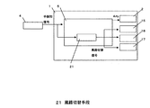
そして、第1のシャッター17、第2のシャッター18、第3のシャッター19の開閉を制御し、素子乾燥用風路20と手乾燥用風路9を切り替えることができる風路切替手段21を制御部5に設けている。
Then, opening / closing of the
上記構成により、手検知手段4からの信号が途絶えたときに、風路切替手段21により手乾燥用風路9から素子乾燥用風路20へ切り替えることによって、第2の吸気口12から吸い込まれた低湿の空気は湿度吸着素子11を通ることとなり、湿度吸着素子11を乾燥させる遅延運転を行うことができる。
With the above configuration, when the signal from the hand detection means 4 is interrupted, the air passage switching means 21 switches from the hand drying air path 9 to the element drying
以上のように、使用後に素子を乾燥させることで次回使用する際に効率よく水を吸着させることができ、効率よく手を乾燥させることができるという効果を奏する。 As described above, by drying the element after use, it is possible to efficiently adsorb water when it is used next time, and it is possible to efficiently dry hands.
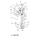
また、図6に示すように、鉛直風路9aは、排気口13の手前で水受け部6側へ風路内の結露水が流れるように配置した傾斜部23を設け、傾斜部23から水受け部6連通させる水排出手段22を備えた構成にしてもよい。
In addition, as shown in FIG. 6, the
上記構成により、遅延運転中に湿度吸着素子11から水が出ても水受け部6へ流れ込む仕組みとなり、水分を外に排出することなく水受け部6に流すことができ、使用感が向上するという効果を奏する。
With the above configuration, even if water comes out from the
(実施の形態3)
実施の形態1で既に説明した部分については理解を容易にするために、同一番号を付し、説明は簡略化する。
(Embodiment 3)
Parts that have already been described in the first embodiment are given the same numbers for ease of understanding, and the description will be simplified.
実施の形態3の手乾燥装置においては、素子の性能を維持するための遅延運転の停止タイミングについて説明をする。 In the hand dryer according to the third embodiment, the stop timing of the delayed operation for maintaining the performance of the element will be described.
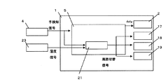
すなわち本実施の形態では、図7、図8に示すように湿度吸着素子11に隣接させて湿度を検出することができる湿度検出手段24を加えて設ける構成とした。
That is, in the present embodiment, as shown in FIGS. 7 and 8, the humidity detecting means 24 capable of detecting the humidity is provided adjacent to the
湿度検出手段24により検出された湿度がある一定値以下になった場合、例えば10%以下になった時は湿度吸着素子11が十分に乾燥したと判断し、遅延運転を停止する。
When the humidity detected by the
以上のように、湿度吸着素子11の遅延運転を十分に行うことで次に使用する際の前記湿度吸着素子11を常に最適な状態で使用することができ、効率よく手を乾燥させることができるという効果を奏する。
As described above, by sufficiently performing the delay operation of the
本発明の手乾燥装置は、レストランやホテルなどの洗面所やトイレに設置され、また病院や手術室や調理場においても適用できる。 The hand-drying apparatus of the present invention is installed in a bathroom or toilet such as a restaurant or hotel, and can also be applied in a hospital, an operating room, or a kitchen.
1 本体
2 送風手段
3 乾燥空間
4 手検知手段
5 制御部
6 水受け部
7 第1の吸気口
8 吹出口
9 手乾燥用風路
9a 鉛直風路
10 風路作成用板
11 湿度吸着素子
12 第2の吸気口
13 排気口
14 内部風路
15 吸入口
16 吐出口
17 第1のシャッター
18 第2のシャッター
19 第3のシャッター
20 素子乾燥用風路
21 風路切替手段
22 水排出手段
24 湿度検出手段
DESCRIPTION OF
Claims (4)
Priority Applications (1)
| Application Number | Priority Date | Filing Date | Title |
|---|---|---|---|
| JP2012059789A JP2013192588A (en) | 2012-03-16 | 2012-03-16 | Hand dryer |
Applications Claiming Priority (1)
| Application Number | Priority Date | Filing Date | Title |
|---|---|---|---|
| JP2012059789A JP2013192588A (en) | 2012-03-16 | 2012-03-16 | Hand dryer |
Publications (1)
| Publication Number | Publication Date |
|---|---|
| JP2013192588A true JP2013192588A (en) | 2013-09-30 |
Family
ID=49392270
Family Applications (1)
| Application Number | Title | Priority Date | Filing Date |
|---|---|---|---|
| JP2012059789A Pending JP2013192588A (en) | 2012-03-16 | 2012-03-16 | Hand dryer |
Country Status (1)
| Country | Link |
|---|---|
| JP (1) | JP2013192588A (en) |
Cited By (4)
| Publication number | Priority date | Publication date | Assignee | Title |
|---|---|---|---|---|
| WO2019035203A1 (en) * | 2017-08-17 | 2019-02-21 | 三菱電機株式会社 | Hand drying device |
| CN116269018A (en) * | 2023-03-23 | 2023-06-23 | 九牧厨卫股份有限公司 | Towel rail and its control method and control device |
| WO2024192837A1 (en) * | 2023-03-22 | 2024-09-26 | 张少洋 | Hand dryer |
| WO2024235336A1 (en) * | 2023-05-18 | 2024-11-21 | 科勒(中国)投资有限公司 | Hand dryer |
-
2012
- 2012-03-16 JP JP2012059789A patent/JP2013192588A/en active Pending
Cited By (4)
| Publication number | Priority date | Publication date | Assignee | Title |
|---|---|---|---|---|
| WO2019035203A1 (en) * | 2017-08-17 | 2019-02-21 | 三菱電機株式会社 | Hand drying device |
| WO2024192837A1 (en) * | 2023-03-22 | 2024-09-26 | 张少洋 | Hand dryer |
| CN116269018A (en) * | 2023-03-23 | 2023-06-23 | 九牧厨卫股份有限公司 | Towel rail and its control method and control device |
| WO2024235336A1 (en) * | 2023-05-18 | 2024-11-21 | 科勒(中国)投资有限公司 | Hand dryer |
Similar Documents
| Publication | Publication Date | Title |
|---|---|---|
| CN106120238B (en) | A kind of roller washing machine | |
| KR102118045B1 (en) | Clothes Treating Apparatus | |
| TW200716810A (en) | Drum type drying and washing machine | |
| CN204838968U (en) | Chopsticks cage | |
| JP2013192588A (en) | Hand dryer | |
| CN106466170A (en) | A kind of use in dishwasher wind path circulating device and dish-washing machine | |
| CN205425117U (en) | Bathroom is with warm blower device | |
| JP2004333071A (en) | Two-room heating system | |
| JP2003213764A (en) | Toilet equipment | |
| CN108978143A (en) | A kind of multifunctional intellectual dryer | |
| CN210384461U (en) | Air duct structure of disinfection cabinet | |
| CN111481690B (en) | A kind of air duct structure of disinfection cabinet | |
| CN115897122A (en) | Double-drum clothes treatment equipment | |
| CN114711655B (en) | Hand drier | |
| CN204207655U (en) | Injecting type hand dryer | |
| TW201709860A (en) | Slim type hand washing apparatus with automatic drying function | |
| CN112244682A (en) | A drainage device and hand dryer | |
| TWI429805B (en) | Dryers and laundry dryers | |
| JP4247636B2 (en) | Bathroom Dryer | |
| JP4792794B2 (en) | Hand dryer | |
| JP5637829B2 (en) | Indoor dehumidifier | |
| CN202128394U (en) | Multifunctional hand dryer | |
| JP2014084711A (en) | Drying and deodorizing device of hot-water washing machine | |
| JP2005291668A (en) | Bathroom drying system | |
| CN213588142U (en) | Foot dryer |