JP2013200438A - microscope - Google Patents
microscope Download PDFInfo
- Publication number
- JP2013200438A JP2013200438A JP2012068627A JP2012068627A JP2013200438A JP 2013200438 A JP2013200438 A JP 2013200438A JP 2012068627 A JP2012068627 A JP 2012068627A JP 2012068627 A JP2012068627 A JP 2012068627A JP 2013200438 A JP2013200438 A JP 2013200438A
- Authority
- JP
- Japan
- Prior art keywords
- subject
- optical member
- lens
- optical
- light
- Prior art date
- Legal status (The legal status is an assumption and is not a legal conclusion. Google has not performed a legal analysis and makes no representation as to the accuracy of the status listed.)
- Pending
Links
Images
Classifications
-
- G—PHYSICS
- G01—MEASURING; TESTING
- G01B—MEASURING LENGTH, THICKNESS OR SIMILAR LINEAR DIMENSIONS; MEASURING ANGLES; MEASURING AREAS; MEASURING IRREGULARITIES OF SURFACES OR CONTOURS
- G01B9/00—Measuring instruments characterised by the use of optical techniques
- G01B9/04—Measuring microscopes
-
- G—PHYSICS
- G01—MEASURING; TESTING
- G01B—MEASURING LENGTH, THICKNESS OR SIMILAR LINEAR DIMENSIONS; MEASURING ANGLES; MEASURING AREAS; MEASURING IRREGULARITIES OF SURFACES OR CONTOURS
- G01B9/00—Measuring instruments characterised by the use of optical techniques
- G01B9/02—Interferometers
- G01B9/02049—Interferometers characterised by particular mechanical design details
Landscapes
- Physics & Mathematics (AREA)
- General Physics & Mathematics (AREA)
- Microscoopes, Condenser (AREA)
Abstract
【課題】異なる倍率の被検体像を良好に撮影することができる顕微鏡を提供する。
【解決手段】対物レンズ4と、照明部10と、被検体から前記対物レンズに入射された被検体光の光路を二つの光路に分割する第1の光学部材44と、前記第1の光学部材において反射された被検体光に基づく被検体像を第1の撮像素子14に結像させる第1の結像レンズ46と、前記第1の光学部材を透過した被検体光の光路を二つの光路に分割する第2の光学部材48と、前記第2の光学部材において反射された被検体光に基づく被検体像を第2の撮像素子18に結像させる第2の結像レンズ50と、前記第2の光学部材を透過した被検体光に基づく被検体像を第3の撮像素子22に結像させる第3の結像レンズ56とを備え、前記照明部から射出された前記照明光は、前記対物レンズと前記第1の光学部材との間の光路内に配置された第3の光学部材40を介して前記対物レンズに入射される。
【選択図】図1Provided is a microscope capable of favorably photographing subject images of different magnifications.
An objective lens, an illuminating unit, a first optical member that divides an optical path of subject light incident on the objective lens from a subject into two optical paths, and the first optical member. The first imaging lens 46 that forms an object image based on the object light reflected at the first imaging element 14 and the optical path of the object light transmitted through the first optical member are two optical paths. A second optical member 48 that divides into two, a second imaging lens 50 that forms a subject image based on subject light reflected by the second optical member on the second imaging element 18, and A third imaging lens 56 that forms an object image based on the object light transmitted through the second optical member on the third imaging element 22, and the illumination light emitted from the illumination unit is Arranged in the optical path between the objective lens and the first optical member Through the third optical member 40 is incident on the objective lens.
[Selection] Figure 1
Description
本発明は、被検体像を異なる倍率で撮像素子に結像させる顕微鏡に関するものである。 The present invention relates to a microscope that forms an image of a subject on an image sensor at different magnifications.
従来、一つの対物レンズと二つの異なる倍率の結像レンズを備えた測定顕微鏡装置が存在する(例えば、特許文献1参照)。この測定顕微鏡装置によれば、対物レンズの切換えを行わずに二つの異なる倍率の被検体像を撮影することができる。 Conventionally, there is a measurement microscope apparatus including one objective lens and two imaging lenses with different magnifications (see, for example, Patent Document 1). According to this measurement microscope apparatus, it is possible to photograph subject images at two different magnifications without switching the objective lens.
しかしながら、上述の測定顕微鏡装置において、照明部を対物レンズから離れた位置に設置した場合、照明部から射出された照明光は、複数の光学部材を介した後に対物レンズに入射し被検体を照明することになる。 However, in the measurement microscope apparatus described above, when the illumination unit is installed at a position away from the objective lens, the illumination light emitted from the illumination unit enters the objective lens after passing through a plurality of optical members to illuminate the subject. Will do.
この場合、照明光の光量損失が大きくなるため、十分な明るさで被検体を照明することができず、被検体像を良好に撮影することができないという問題があった。 In this case, since the loss of the amount of illumination light increases, there is a problem that the subject cannot be illuminated with sufficient brightness, and the subject image cannot be captured well.
本発明の目的は、異なる倍率の被検体像を良好に撮影することができる顕微鏡を提供することである。 The objective of this invention is providing the microscope which can image | photograph the object image of a different magnification favorably.
本発明の顕微鏡は、所定の倍率で被検体を観察する対物レンズと、前記対物レンズを介して前記被検体を照明する照明光を射出する光源を有する照明部と、前記被検体から前記対物レンズに入射された被検体光の光路を二つの光路に分割する第1の光学部材と、前記第1の光学部材において反射された被検体光に基づく被検体像を第1の撮像素子に結像させる第1の結像レンズと、前記第1の光学部材を透過した被検体光の光路を二つの光路に分割する第2の光学部材と、前記第2の光学部材において反射された被検体光に基づく被検体像を第2の撮像素子に結像させる第2の結像レンズと、前記第2の光学部材を透過した被検体光に基づく被検体像を第3の撮像素子に結像させる第3の結像レンズとを備え、前記照明部から射出された前記照明光は、前記対物レンズと前記第1の光学部材との間の光路内に配置された第3の光学部材を介して前記対物レンズに入射されることを特徴とする。 The microscope according to the present invention includes an objective lens that observes the subject at a predetermined magnification, an illumination unit that emits illumination light that illuminates the subject via the objective lens, and the objective lens from the subject. A first optical member that divides the optical path of the subject light incident on the light into two optical paths, and a subject image based on the subject light reflected by the first optical member on the first imaging element A first imaging lens to be formed, a second optical member that divides the optical path of the subject light transmitted through the first optical member into two optical paths, and the subject light reflected by the second optical member A second imaging lens that forms a subject image based on the second imaging element and a subject image based on the subject light transmitted through the second optical member on the third imaging element. A third imaging lens, and emitted from the illumination unit Meiko is characterized in that it is incident on the objective lens through the third optical member disposed in an optical path between said objective lens first optical member.
また、本発明の顕微鏡は、前記照明部が、前記光源から射出された照明光を所定の位置に集光する集光レンズを備えることを特徴とする。 Moreover, the microscope of the present invention is characterized in that the illumination unit includes a condensing lens that condenses illumination light emitted from the light source at a predetermined position.
また、本発明の顕微鏡は、前記第1の撮像素子、前記第2の撮像素子、及び前記第3の撮像素子に結像される被検体像の倍率が、それぞれ低倍率、高倍率、及び中倍率であることを特徴とする。 In the microscope of the present invention, the magnification of the subject image formed on the first image sensor, the second image sensor, and the third image sensor is low, high, and medium, respectively. It is characterized by a magnification.
また、本発明の顕微鏡は、前記第2の光学部材を透過した被検体光の光路を二つの光路に分割する第4の光学部材と、前記第4の光学部材を透過した被検体光を集光する少なくとも一つの結像レンズと、前記少なくとも一つの結像レンズによって集光された被検体光に基づく被検体像を撮像する少なくとも一つの撮像素子とを備え、前記第3の撮像素子は、前記第4の光学部材において反射され、前記第3の結像レンズによって集光された被検体光に基づく被検体像を撮像することを特徴とする。 Further, the microscope of the present invention collects the fourth optical member that divides the optical path of the subject light transmitted through the second optical member into two optical paths, and the subject light transmitted through the fourth optical member. At least one imaging lens that illuminates; and at least one imaging element that images a subject image based on subject light collected by the at least one imaging lens; and the third imaging element comprises: A subject image based on subject light reflected by the fourth optical member and collected by the third imaging lens is picked up.
本発明の顕微鏡によれば、異なる倍率の被検体像を良好に撮影することができる。 According to the microscope of the present invention, it is possible to properly photograph subject images with different magnifications.
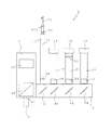
以下、図面を参照して、本発明の実施の形態に係る顕微鏡について説明する。図1は、実施の形態に係る顕微鏡の内部の構成を示す図である。顕微鏡2は、液晶パネルや有機ELパネル等のフラットパネルの生産工程において使用される検査装置に備えられるものであり、所定の倍率(例えば対物50倍)で被検体(不図示)を観察する対物レンズ4が下部に取付けられた筐体6、及び対物レンズ4に入射した被検体光の光路となる光路ボックス8を備えている。
Hereinafter, a microscope according to an embodiment of the present invention will be described with reference to the drawings. FIG. 1 is a diagram illustrating an internal configuration of a microscope according to an embodiment. The
また、光路ボックス8の上部には、対物レンズ4に近い側から順に、対物レンズ4を介して被検体を照明する照明光を射出する照明部10、照明光により照明された被検体の被検体像を撮影する第1のカメラ14を備える第1の鏡筒16、第2のカメラ18を備える第2の鏡筒20、及び第3のカメラ22を備える第3の鏡筒24が備えられている。また、筐体6には、レーザー光を用いて対物レンズ4の焦点調整を行うレーザーオートフォーカス装置25が組み込まれている。
In addition, an
次に、図面を参照して実施の形態に係る顕微鏡2の処理について説明する。まず、レーザーオートフォーカス装置25によりレーザー光が射出されると、レーザー光はダイクロイックミラー26を透過し、対物レンズ4を介して被検体を照射する。被検体で反射された反射光は、対物レンズ4を介してダイクロイックミラー26を透過し、レーザーオートフォーカス装置25に入射する。そして、レーザーオートフォーカス装置25に入射した情報に基づいて対物レンズ4の焦点が調整される。
Next, processing of the
次に、光ファイバー32の端部32aから照明光が射出されると、照明光は、第1の集光レンズ34により集光ポイント36に集光される。次に、照明光は、集光ポイント36を疑似的な点光源として下方に進行した後、第2の集光レンズ38に入射し、ハーフミラー40及びダイクロイックミラー26で反射された後に対物レンズ4の入射部42に集光される。次に、照明光は、入射部42を疑似的な点光源として対物レンズ4に入射し、対物レンズ4を介して被検体を照明する。
Next, when the illumination light is emitted from the end portion 32 a of the
被検体により反射された被検体光は、対物レンズ4に入射し、ダイクロイックミラー26で反射された後、ハーフミラー40を透過する。ハーフミラー40を透過した被検体光の光路は、第1のビームスプリッタ(第1BS)44において二つの光路に分割される。
The subject light reflected by the subject enters the objective lens 4, is reflected by the
第1BS44で反射された被検体光は、第1の結像レンズ46により集光され、第1のカメラ14の図示しない第1の撮像素子に結像される。ここで、第1の結像レンズ46の倍率が0.5倍である場合、第1のカメラ14によって25倍(対物50倍×0.5倍)の被検体像が撮影される。
The subject light reflected by the
一方、第1BS44を透過した被検体光の光路は、第2のビームスプリッタ(第2BS)48において二つの光路に分割される。
On the other hand, the optical path of the subject light transmitted through the
第2BS48において反射された被検体光は、第2の結像レンズ50及びテレコンバージョンレンズ52により集光され、第2のカメラ18の図示しない第2の撮像素子に結像される。ここで、第2の結像レンズ50の倍率が1.0倍、テレコンバージョンレンズ52の倍率が2.0倍である場合、第2のカメラ18によって100倍(対物50倍×1.0倍×2.0倍)の被検体像が撮影される。
The subject light reflected by the
一方、第2BS48を透過した被検体光は、全反射ミラー54において全反射され、第3の結像レンズ56により集光された後、第3のカメラ22の図示しない第3の撮像素子に結像される。ここで、第3の結像レンズ56の倍率が1.0倍である場合、第3のカメラ22によって50倍(対物50倍×1.0倍)の被検体像が撮影される。
On the other hand, the subject light that has passed through the
即ち、第1のカメラ14、第2のカメラ18、及び第3のカメラ22によって、25倍、100倍、50倍の3種類の倍率(1:4:2の比率)の被検体像が撮影される。
That is, the
この実施の形態に係る顕微鏡2によれば、照明部10を第1の鏡筒16よりも対物レンズ4側に配置し、複数のミラー等を透過をすることによる光量損失の少ない照明光で明るく被検体を照明できるため、それぞれの撮像素子に適切な光量の被検体像を結像させることができ、3種の異なる倍率の被検体像を良好に撮影することができる。
According to the
また、3種の異なる倍率の被検体像を撮影することができるため、近年高精細化する被検体を最適な倍率で的確に検査することができる。また、対物レンズ4の切換えを行わずに効率よく被検体を検査することができる。 In addition, since three types of subject images with different magnifications can be taken, it is possible to accurately examine a subject whose resolution has been increased in recent years at an optimum magnification. In addition, the subject can be inspected efficiently without switching the objective lens 4.
また、光ファイバー32の端部32aから射出された照明光を一旦第1の集光レンズ34により集光ポイント36に集光し、疑似的な点光源を生成してケーラー照明により被検体の照明を行うことから、照明効率を高くすることができる。
Further, the illumination light emitted from the end portion 32a of the
また、被検体光の光路長さ及び被検体光の光量損失を考慮し、対物レンズ4に近い側から、照明部10、第1の鏡筒16、第2の鏡筒20、及び第3の鏡筒24の順に配置することにより、最大の倍率である100倍の被検体像の精度を最も高くすることができる。
Further, in consideration of the optical path length of the subject light and the light quantity loss of the subject light, the
なお、上述の実施の形態においては、対物レンズ4の倍率が対物50倍の場合を例に説明しているが、良好な被検体像を撮影することができれば、対物レンズ4の倍率は上述の例に限定されない。また、それぞれの結像レンズの倍率も上述の例に限定されない。 In the above-described embodiment, the case where the magnification of the objective lens 4 is 50 × objective is described as an example. However, if a good subject image can be captured, the magnification of the objective lens 4 is as described above. It is not limited to examples. Further, the magnification of each imaging lens is not limited to the above example.
また、上述の実施の形態において、テレコンバージョンレンズ52の倍率は上述の例に限定されない。なお、例えば、テレコンバージョンレンズ52の倍率を4倍とした場合、第2のカメラ18により200倍(対物50倍×1.0倍×4.0倍)の被検体像を撮影することができ、1:8:2の3種類の比率の被検体像を得ることができる。
In the above-described embodiment, the magnification of the
また、上述の実施の形態においては、光ファイバー32の端部32aを光源として照明光が射出される場合を例に説明しているが、照明光の光源は光ファイバー32に限定されない。例えば、光ファイバー32に代えて、照明部10にLED光源等を接続するようにしてもよい。
Further, in the above-described embodiment, the case where illumination light is emitted using the end portion 32a of the
また、上述の実施の形態においては、顕微鏡2が3つの鏡筒を備え、3種の異なる倍率の被検体像を得ることができる場合を例に説明しているが、良好な被検体像を撮影することができれば、更に鏡筒を増設してもよい。
In the above-described embodiment, the case where the
2…顕微鏡、4…対物レンズ、6…筐体、8…光路ボックス、10…照明部、14…第1のカメラ、16…第1の鏡筒、18…第2のカメラ、20…第2の鏡筒、22…第3のカメラ、24…第3の鏡筒、26…ダイクロイックミラー、32…光ファイバー、34…第1の集光レンズ、38…第2の集光レンズ、40…ハーフミラー、44…第1BS、46…第1の結像レンズ、48…第2BS、50…第2の結像レンズ、52…テレコンバージョンレンズ、54…全反射ミラー、56…第3の結像レンズ
DESCRIPTION OF
Claims (4)
前記対物レンズを介して前記被検体を照明する照明光を射出する光源を有する照明部と、
前記被検体から前記対物レンズに入射された被検体光の光路を二つの光路に分割する第1の光学部材と、
前記第1の光学部材において反射された被検体光に基づく被検体像を第1の撮像素子に結像させる第1の結像レンズと、
前記第1の光学部材を透過した被検体光の光路を二つの光路に分割する第2の光学部材と、
前記第2の光学部材において反射された被検体光に基づく被検体像を第2の撮像素子に結像させる第2の結像レンズと、
前記第2の光学部材を透過した被検体光に基づく被検体像を第3の撮像素子に結像させる第3の結像レンズとを備え、
前記照明部から射出された前記照明光は、前記対物レンズと前記第1の光学部材との間の光路内に配置された第3の光学部材を介して前記対物レンズに入射されることを特徴とする顕微鏡。 An objective lens for observing the subject at a predetermined magnification;
An illumination unit having a light source that emits illumination light that illuminates the subject through the objective lens;
A first optical member that divides an optical path of subject light incident on the objective lens from the subject into two optical paths;
A first imaging lens that forms an object image based on the object light reflected by the first optical member on the first image sensor;
A second optical member that divides the optical path of the subject light transmitted through the first optical member into two optical paths;
A second imaging lens that forms a subject image based on the subject light reflected by the second optical member on a second imaging element;
A third imaging lens that forms a subject image based on the subject light transmitted through the second optical member on a third imaging element;
The illumination light emitted from the illumination unit is incident on the objective lens via a third optical member disposed in an optical path between the objective lens and the first optical member. A microscope.
前記第4の光学部材を透過した被検体光を集光する少なくとも一つの結像レンズと、
前記少なくとも一つの結像レンズによって集光された被検体光に基づく被検体像を撮像する少なくとも一つの撮像素子とを備え、
前記第3の撮像素子は、前記第4の光学部材において反射され、前記第3の結像レンズによって集光された被検体光に基づく被検体像を撮像することを特徴とする請求項1〜3の何れか一項に記載の顕微鏡。
A fourth optical member that divides the optical path of the subject light transmitted through the second optical member into two optical paths;
At least one imaging lens for condensing the subject light transmitted through the fourth optical member;
Comprising at least one imaging element for imaging a subject image based on subject light collected by the at least one imaging lens;
The third imaging element picks up a subject image based on subject light reflected by the fourth optical member and collected by the third imaging lens. 4. The microscope according to any one of 3.
Priority Applications (3)
| Application Number | Priority Date | Filing Date | Title |
|---|---|---|---|
| JP2012068627A JP2013200438A (en) | 2012-03-26 | 2012-03-26 | microscope |
| CN2013100975789A CN103364935A (en) | 2012-03-26 | 2013-03-25 | Microscope |
| KR1020130031513A KR20130109057A (en) | 2012-03-26 | 2013-03-25 | microscope |
Applications Claiming Priority (1)
| Application Number | Priority Date | Filing Date | Title |
|---|---|---|---|
| JP2012068627A JP2013200438A (en) | 2012-03-26 | 2012-03-26 | microscope |
Publications (1)
| Publication Number | Publication Date |
|---|---|
| JP2013200438A true JP2013200438A (en) | 2013-10-03 |
Family
ID=49366667
Family Applications (1)
| Application Number | Title | Priority Date | Filing Date |
|---|---|---|---|
| JP2012068627A Pending JP2013200438A (en) | 2012-03-26 | 2012-03-26 | microscope |
Country Status (3)
| Country | Link |
|---|---|
| JP (1) | JP2013200438A (en) |
| KR (1) | KR20130109057A (en) |
| CN (1) | CN103364935A (en) |
Cited By (1)
| Publication number | Priority date | Publication date | Assignee | Title |
|---|---|---|---|---|
| CN116931236A (en) * | 2023-09-14 | 2023-10-24 | 长春长光智欧科技有限公司 | Double-rate optical system based on probe alignment wafer |
Families Citing this family (1)
| Publication number | Priority date | Publication date | Assignee | Title |
|---|---|---|---|---|
| CN105118088A (en) * | 2015-08-06 | 2015-12-02 | 曲阜裕隆生物科技有限公司 | 3D imaging and fusion method based on pathological slice scanning device |
Citations (4)
| Publication number | Priority date | Publication date | Assignee | Title |
|---|---|---|---|---|
| US4777525A (en) * | 1985-12-23 | 1988-10-11 | Preston Jr Kendall | Apparatus and method for a multi-resolution electro-optical imaging, display and storage/retrieval system |
| JP2004512845A (en) * | 2000-10-24 | 2004-04-30 | オンコシス リミテッド ライアビリティ カンパニー | Methods and devices for selectively targeting cells in a three-dimensional specimen |
| JP2006138928A (en) * | 2004-11-10 | 2006-06-01 | Olympus Corp | Living body observing apparatus |
| JP2006276663A (en) * | 2005-03-30 | 2006-10-12 | Olympus Corp | microscope |
Family Cites Families (11)
| Publication number | Priority date | Publication date | Assignee | Title |
|---|---|---|---|---|
| IL111229A (en) * | 1994-10-10 | 1998-06-15 | Nova Measuring Instr Ltd | Autofocusing microscope |
| US5760901A (en) * | 1997-01-28 | 1998-06-02 | Zetetic Institute | Method and apparatus for confocal interference microscopy with background amplitude reduction and compensation |
| JP4185711B2 (en) * | 2002-06-10 | 2008-11-26 | 株式会社キーエンス | Microscope with multiple light sources |
| JP4242617B2 (en) * | 2002-08-28 | 2009-03-25 | オリンパス株式会社 | Scanning laser microscope system |
| US7283241B2 (en) * | 2005-01-31 | 2007-10-16 | Chemimage Corp. | Method and apparatus for a microscope image selector |
| US9234845B2 (en) * | 2006-10-19 | 2016-01-12 | Olympus Corporation | Microscope with reflecting fluorescence illumination optical system |
| US20100118297A1 (en) * | 2007-11-21 | 2010-05-13 | Star Technologies Inc. | Microscope having multiple image-outputting devices and probing apparatus for integrated circuit devices using the same |
| KR100945206B1 (en) * | 2008-04-10 | 2010-03-03 | 주식회사 에이치앤씨 | Optical measuring device and inspection device including the same |
| JP2010204594A (en) * | 2009-03-06 | 2010-09-16 | Nikon Corp | Imaging device and microscope |
| US20100277794A1 (en) * | 2009-04-30 | 2010-11-04 | Olympus Corporation | Microscope |
| CN102096192B (en) * | 2010-12-30 | 2013-01-16 | 长春光华微电子设备工程中心有限公司 | Multi-magnification imaging optical system |
-
2012
- 2012-03-26 JP JP2012068627A patent/JP2013200438A/en active Pending
-
2013
- 2013-03-25 KR KR1020130031513A patent/KR20130109057A/en not_active Ceased
- 2013-03-25 CN CN2013100975789A patent/CN103364935A/en active Pending
Patent Citations (4)
| Publication number | Priority date | Publication date | Assignee | Title |
|---|---|---|---|---|
| US4777525A (en) * | 1985-12-23 | 1988-10-11 | Preston Jr Kendall | Apparatus and method for a multi-resolution electro-optical imaging, display and storage/retrieval system |
| JP2004512845A (en) * | 2000-10-24 | 2004-04-30 | オンコシス リミテッド ライアビリティ カンパニー | Methods and devices for selectively targeting cells in a three-dimensional specimen |
| JP2006138928A (en) * | 2004-11-10 | 2006-06-01 | Olympus Corp | Living body observing apparatus |
| JP2006276663A (en) * | 2005-03-30 | 2006-10-12 | Olympus Corp | microscope |
Cited By (2)
| Publication number | Priority date | Publication date | Assignee | Title |
|---|---|---|---|---|
| CN116931236A (en) * | 2023-09-14 | 2023-10-24 | 长春长光智欧科技有限公司 | Double-rate optical system based on probe alignment wafer |
| CN116931236B (en) * | 2023-09-14 | 2023-11-28 | 长春长光智欧科技有限公司 | Double-rate optical system based on probe alignment wafer |
Also Published As
| Publication number | Publication date |
|---|---|
| KR20130109057A (en) | 2013-10-07 |
| CN103364935A (en) | 2013-10-23 |
Similar Documents
| Publication | Publication Date | Title |
|---|---|---|
| US9810896B2 (en) | Microscope device and microscope system | |
| US8809809B1 (en) | Apparatus and method for focusing in fluorescence microscope | |
| JP5601539B2 (en) | Three-dimensional direction drift control device and microscope device | |
| CN103109152B (en) | Selective high speed acquisition vision system and method for observing object features | |
| JP2012008450A (en) | Microscope and focusing method | |
| KR101568980B1 (en) | Automatic focus control apparatus and automatic focus control method using the same | |
| JP2021107926A (en) | Optical configuration for imaging sample | |
| JPWO2008062651A1 (en) | Image measuring instrument | |
| JPWO2020021663A1 (en) | Microscope device | |
| JP2010220892A5 (en) | ||
| JP2012042564A (en) | Microscope and ghost removing method | |
| JP2006201465A5 (en) | ||
| JP2013200438A (en) | microscope | |
| JP5959247B2 (en) | microscope | |
| JP2012181341A (en) | Microscope device | |
| JP2010054465A (en) | Observation apparatus | |
| JP2010008458A (en) | Optical measuring instrument and pattern formed on projection plate | |
| JP2012141452A (en) | Automatic focus mechanism and microscope device | |
| JP2008197283A (en) | Slit scanning confocal microscope and image acquisition method | |
| KR20170137723A (en) | Appearance inspection device | |
| JP2011242702A (en) | Imaging optical system and shape measurement apparatus | |
| JP2013174709A (en) | Microscope device and virtual microscope device | |
| JP4713391B2 (en) | Infrared microscope | |
| JP2010054981A (en) | Confocal microscope apparatus | |
| JP2011102817A (en) | Microscope device |
Legal Events
| Date | Code | Title | Description |
|---|---|---|---|
| A621 | Written request for application examination |
Free format text: JAPANESE INTERMEDIATE CODE: A621 Effective date: 20150313 |
|
| A131 | Notification of reasons for refusal |
Free format text: JAPANESE INTERMEDIATE CODE: A131 Effective date: 20160209 |
|
| A977 | Report on retrieval |
Free format text: JAPANESE INTERMEDIATE CODE: A971007 Effective date: 20160210 |
|
| A02 | Decision of refusal |
Free format text: JAPANESE INTERMEDIATE CODE: A02 Effective date: 20160802 |