JP2013200465A - Rear projection type video display device - Google Patents
Rear projection type video display device Download PDFInfo
- Publication number
- JP2013200465A JP2013200465A JP2012069149A JP2012069149A JP2013200465A JP 2013200465 A JP2013200465 A JP 2013200465A JP 2012069149 A JP2012069149 A JP 2012069149A JP 2012069149 A JP2012069149 A JP 2012069149A JP 2013200465 A JP2013200465 A JP 2013200465A
- Authority
- JP
- Japan
- Prior art keywords
- cam
- rear projection
- projection type
- display device
- screen unit
- Prior art date
- Legal status (The legal status is an assumption and is not a legal conclusion. Google has not performed a legal analysis and makes no representation as to the accuracy of the status listed.)
- Pending
Links
Images






Landscapes
- Overhead Projectors And Projection Screens (AREA)
- Transforming Electric Information Into Light Information (AREA)
Abstract
【課題】スクリーンユニットの位置を容易に調整することが可能な背面投射型映像表示装置を提供する。
【解決手段】背面投射型映像表示装置100が備える平面カム13は、該平面カム13が回転することにより前記スクリーンユニット3を上下方向に移動させるように設けられる。また、背面投射型映像表示装置100は、キャビネット4の外部からの操作により平面カム13を回転させるための長棒10を備える。
【選択図】図6A rear projection image display apparatus capable of easily adjusting the position of a screen unit is provided.
A flat cam 13 provided in a rear projection type image display device 100 is provided so as to move the screen unit 3 in the vertical direction as the flat cam 13 rotates. Further, the rear projection type image display device 100 includes a long bar 10 for rotating the flat cam 13 by an operation from the outside of the cabinet 4.
[Selection] Figure 6
Description
本発明は、スクリーンユニットの位置調整を行う構成を有する、大画面表示システムを構成する各背面投射型映像表示装置に関する。 The present invention relates to each rear projection type video display device constituting a large screen display system having a configuration for adjusting the position of a screen unit.
近年、映像技術の向上および映像の高画質化の要求が高まり、また地上放送のデジタル化によって、従来使用されてきたNTSC(National Television System Committee)方式といったアナログ方式に変わり、映像のデジタル化、ハイビジョン画質の用途が急速に高まってきている。この映像の高精細化の要求は、家庭での視聴のみならず、各種インフラにおける監視活動や映像を用いた情報案内といった業務用途においても、映像のデジタル化・高精細化が求められつつある。 In recent years, the demand for improved video technology and higher image quality has increased, and the digitalization of terrestrial broadcasts has changed to the analog system such as the NTSC (National Television System Committee) system that has been used in the past. The use of image quality is increasing rapidly. The demand for high-definition video is required not only for viewing at home, but also for business use such as monitoring activities in various infrastructures and information guidance using video.
大画面の映像機器を用いることで、多人数での映像の監視や視聴が可能となる一方、複数の映像機器を組み合せた映像一面のなかに、様々な映像ソースを同時に映し出し、膨大な情報量を一時に表示することが可能となる。監視用途に例えれば、地図や路線等の全体情報に加え、各拠点に配備されたカメラからの複数の映像をリアルタイムに一つの画面上に表示して、複数人が異なった位置で同時に映像を視認し情報を共有することができる。 The use of large-screen video equipment enables monitoring and viewing of video by a large number of people, while simultaneously displaying various video sources on a single video that combines multiple video equipment, and enormous amounts of information. Can be displayed at a time. For example, in addition to general information such as maps and routes, multiple images from cameras installed at each site are displayed on a single screen in real time, allowing multiple people to simultaneously view images at different positions. View and share information.
従来、監視や情報案内を行う上で、一つの映像機器を縦横に並べることによって大画面表示システム(マルチビジョン)を構築する手法があり、上記大画面表示システムに使用する映像機器として、背面投射型映像表示装置(リアプロジェクタ)が採用されてきた。 Conventionally, there is a method of constructing a large screen display system (multi-vision) by arranging one video device vertically and horizontally for monitoring and information guidance, and rear projection is used as the video device used for the large screen display system. Type image display devices (rear projectors) have been adopted.
背面投射型映像表示装置は、キャビネット内に配置された投写装置からの映像を視聴者の正面に配置されたスクリーンに背面から投影することで映像を作り出す映像表示機器である。この背面投射型映像表示装置のスクリーンは、フレネルレンズおよびレンチキュラーレンズと呼ばれるアクリル等の透過型樹脂素材による2枚の板状のスクリーンとそれらをユニットとして保持するための金属製の枠にてユニット化される。スクリーンユニットは、キャビネットと固定されるような構造になっている。 A rear projection type video display device is a video display device that creates a video by projecting a video from a projection device arranged in a cabinet onto a screen arranged in front of a viewer from the back. The screen of this rear projection type image display device is unitized by two plate-like screens made of a transparent resin material such as acrylic called Fresnel lens and lenticular lens and a metal frame for holding them as a unit. Is done. The screen unit is structured to be fixed to the cabinet.
背面投射型映像表示装置は、液晶パネルやPDP(Plasma Display Panel)パネルのようにスクリーン周辺に配置する部品が不要である。そのため、各画面周辺の非映像エリアを非常に小さくすることができる。その結果、大画面を構成する上で重要な各映像機器の画面間の繋ぎ目を少なくし、画面全体の一体感および映像の欠落を少なくすることができる。 The rear projection type video display device does not require components arranged around the screen like a liquid crystal panel or a PDP (Plasma Display Panel) panel. Therefore, the non-video area around each screen can be made very small. As a result, it is possible to reduce the number of joints between the screens of video devices that are important in configuring a large screen, and to reduce the sense of unity of the entire screen and the lack of video.
一般的に、背面投射型映像表示装置のキャビネットは、ある程度の剛性および耐震強度を保つために、アルミニウム合金や鉄等の金属部材により構成される。また、透過型スクリーンはアクリル素材等のプラスチックで成形されたものが使用される。金属材料より樹脂性のアクリル素材の方が材料の線膨張係数が大きく、使用される場所の温湿度が上昇すると、キャビネットよりスクリーンの伸び量が大きくなる。 Generally, a cabinet of a rear projection type image display device is made of a metal member such as an aluminum alloy or iron in order to maintain a certain degree of rigidity and earthquake resistance. The transmissive screen is made of a plastic such as an acrylic material. Resin acrylic material has a larger coefficient of linear expansion than metal material, and when the temperature and humidity of the place where it is used rises, the amount of screen expansion becomes larger than the cabinet.
キャビネットとスクリーンの外形寸法(外形サイズ)が同じ場合は、隣接するスクリーン同士が互いに接触して、スクリーン端面にダメージを与えてしまう。また、温湿度上昇によりスクリーン外寸が伸びたときに、外形方向には隣接するスクリーンがあるためにスクリーンが伸張できず、スクリーン自体が反ることがある。 When the external dimensions (external size) of the cabinet and the screen are the same, adjacent screens come into contact with each other and damage the end face of the screen. In addition, when the outer dimension of the screen is extended due to an increase in temperature and humidity, the screen cannot be extended because there is an adjacent screen in the outer direction, and the screen itself may be warped.
そのため、複数の背面投射型映像表示装置を縦横に積み上げて構築された大画面表示システムにおいては、キャビネットの外形寸法(外形サイズ)に対しスクリーンを小さめにしておく必要がある。この隣接するスクリーン間のギャップは目地幅と呼ばれる。 Therefore, in a large screen display system constructed by stacking a plurality of rear projection type video display devices vertically and horizontally, it is necessary to make the screen smaller than the external dimensions (external size) of the cabinet. This gap between adjacent screens is called joint width.
複数の背面投射型映像表示装置を縦横に積み上げて大画面表示システムを構築する際は、まずキャビネットを上下左右に積み上げた後、大画面表示システムの映像が全体に均一になるようにスクリーンを配置する。つまり、目地幅がどのスクリーン間でも均一になるように、見栄えがよくなるようにすることが大事である。その際、隣り合うスクリーン間に各材料の線膨張係数より計算された目地幅分の厚みを持つ板等を挟み込みながらキャビネットとスクリーンを固定する手法が一般的である。しかし、この作業には前面でスクリーン位置を保持する人とキャビネットとスクリーンをネジ等で固定する人の最低二人以上の作業が必須であり、かつスクリーンサイズは1メートル以上と大型である。そのため、スクリーンの位置を調整しキャビネットと固定することが難しい。 When building a large-screen display system by stacking multiple rear-projection image display devices vertically and horizontally, first stack the cabinets vertically and horizontally, and then arrange the screen so that the images of the large-screen display system are uniform throughout To do. In other words, it is important to improve the appearance so that the joint width is uniform between screens. At that time, a general method is to fix the cabinet and the screen while sandwiching a plate having a thickness corresponding to the joint width calculated from the linear expansion coefficient of each material between the adjacent screens. However, this work requires a work of at least two persons: a person holding the screen position on the front side and a person fixing the cabinet and the screen with screws or the like, and the screen size is as large as 1 meter or more. For this reason, it is difficult to adjust the position of the screen and fix it to the cabinet.
上記のように隣り合うスクリーンの各々の位置を調整する技術が、特許文献1,2に開示されている。特許文献1の技術(以下、従来技術Aともいう)では、複数の単位スクリーンをその隣同志の縁部を互いに接着剤で接合して大画面のスクリーンを構成するマルチビジョン装置が開示されている。当該マルチビジョン装置は、目地調整機構を有する。目地調整機構では、スクリーンを単位毎に仕切る仕切板による仕切線の延長線上に目印が設けられる。また、目地調整機構は、隣り合う単位スクリーンの縁部の接着によって生じたスクリーン接着面の延長線を印に一致させるよう、スクリーン接着面の端部を弾性部材と調整ネジとを用いて各スクリーンの位置を調整する機構である。
Techniques for adjusting the positions of adjacent screens as described above are disclosed in
また、特許文献2には、以下の技術(以下、従来技術Bともいう)が開示されている。従来技術Bでは、スクリーンの左右辺または周辺を複数の線材とバネを用いて密着させて張力を付与した状態でキャビネットにスクリーンが吊られているマルチスクリーンプロジェクタにおいて、スクリーンを吊り下げる支持部を調整ネジで上下左右に移動可能にする構成が開示されている。
しかしながら、従来技術A,Bでは、以下の問題がある。 However, the conventional techniques A and B have the following problems.
従来技術Aでは、単位スクリーンの縁部を接着する際に、隣接するスクリーンに接着剤がスクリーン表面に付いてしまう危険性があり、作業内容が非常に繊細となる。特に液状の接着剤を使用する場合、レンチキュラーレンズやフレネルレンズの表面は微細な凹凸の形状を有するため、毛細管現象により接着剤が流れこみやすい。 In the prior art A, there is a risk that the adhesive may adhere to the screen surface when adhering the edge of the unit screen, and the work content becomes very delicate. In particular, when a liquid adhesive is used, the surface of the lenticular lens or the Fresnel lens has a fine uneven shape, so that the adhesive easily flows in due to a capillary phenomenon.
さらに、スクリーンユニットは、ある所定の個数毎にユニット組みされる。そのため、大画面システムで使用されるスクリーンユニットの個数が増えるにつれ、キャビネットとスクリーンユニットを取り付ける前に、各スクリーンユニットを事前に組み立てる必要がある。そのため、広い作業スペースと繊細な作業が必要となる。また、従来技術Aでは、スクリーンユニットの位置を調整するための調整ネジがスクリーンユニットの内部に配置されている。すなわち、従来技術Aでは、スクリーンユニットの位置を調整するのは容易ではないという問題がある。 Further, the screen units are assembled in units of a predetermined number. Therefore, as the number of screen units used in the large screen system increases, it is necessary to assemble each screen unit in advance before attaching the cabinet and the screen unit. Therefore, a large work space and delicate work are required. Moreover, in the prior art A, the adjustment screw for adjusting the position of a screen unit is arrange | positioned inside the screen unit. That is, in the related art A, there is a problem that it is not easy to adjust the position of the screen unit.
また、従来技術Bも、従来技術Aと同様に、スクリーンの位置を調整する調整ネジがスクリーンユニット内部に配置されている。そのため、スクリーンユニットとキャビネットを固定する前に予めスクリーンの位置を決めておく、もしくは各スクリーンユニットを順番に位置決めしながら複数のスクリーンユニットを順次取り付けていく必要がある。 In the conventional technique B, as in the conventional technique A, an adjustment screw for adjusting the position of the screen is arranged inside the screen unit. Therefore, it is necessary to determine the position of the screen in advance before fixing the screen unit and the cabinet, or to sequentially attach a plurality of screen units while positioning each screen unit in turn.
また、従来技術Bでは、仮に、大画面表示システムの運用後に、あるスクリーンユニットを交換する必要が発生した際には、当該スクリーンユニットのみを取り外し、さらに代替のスクリーンユニットを交換前と同じ位置に配置することは非常に困難となる。以上により、従来技術Bでは、スクリーンユニットの位置を調整するのは容易ではないという問題がある。 Further, in the conventional technique B, if a certain screen unit needs to be replaced after the large screen display system is operated, only the screen unit is removed, and an alternative screen unit is placed at the same position as before the replacement. It is very difficult to place. As described above, the conventional technique B has a problem that it is not easy to adjust the position of the screen unit.
本発明は、このような問題を解決するためになされたものであり、スクリーンユニットの位置を容易に調整することが可能な背面投射型映像表示装置を提供することを目的とする。 The present invention has been made to solve such a problem, and an object of the present invention is to provide a rear projection type image display apparatus capable of easily adjusting the position of a screen unit.
上記目的を達成するために、本発明の一態様に係る背面投射型映像表示装置は、スクリーンユニットの背面より映像が投射される。前記背面投射型映像表示装置は、回転自在に設けられ、回転軸が偏芯された平面カムと、前記スクリーンユニットと組み合わされて、前記平面カムを覆うキャビネットと、を備え、前記平面カムは、該平面カムが回転することにより前記スクリーンユニットを所定方向に移動させるように設けられ、前記背面投射型映像表示装置は、さらに、前記キャビネットの外部からの操作により前記平面カムを回転させるための回転機構を備える。 In order to achieve the above object, in the rear projection type image display device according to one aspect of the present invention, an image is projected from the rear surface of the screen unit. The rear projection type image display device includes a planar cam that is rotatably provided and has a rotating shaft that is eccentric, and a cabinet that is combined with the screen unit and covers the planar cam. The screen unit is provided to move the screen unit in a predetermined direction by rotating the flat cam, and the rear projection type image display device further rotates to rotate the flat cam by an operation from outside the cabinet. Provide mechanism.
本発明によれば、背面投射型映像表示装置が備える前記平面カムは、該平面カムが回転することにより前記スクリーンユニットを所定方向に移動させるように設けられる。また、背面投射型映像表示装置は、前記キャビネットの外部からの操作により前記平面カムを回転させるための回転機構を備える。 According to the present invention, the flat cam provided in the rear projection type image display device is provided so as to move the screen unit in a predetermined direction as the flat cam rotates. Further, the rear projection type video display device includes a rotation mechanism for rotating the flat cam by an operation from outside the cabinet.
すなわち、外部からの操作により前記平面カムを回転させることができる。これにより、スクリーンユニットを所定方向に移動させることができる。したがって、スクリーンユニットの位置を容易に調整することができる。 That is, the planar cam can be rotated by an external operation. Thereby, the screen unit can be moved in a predetermined direction. Therefore, the position of the screen unit can be easily adjusted.
以下、図面を参照しつつ、本発明の実施の形態について説明する。以下の説明では、同一の構成要素には同一の符号を付してある。それらの名称および機能も同じである。したがって、それらについての詳細な説明を省略する場合がある。 Hereinafter, embodiments of the present invention will be described with reference to the drawings. In the following description, the same components are denoted by the same reference numerals. Their names and functions are also the same. Therefore, detailed description thereof may be omitted.
なお、実施の形態において例示される各構成要素の寸法、材質、形状、それらの相対配置などは、本発明が適用される装置の構成や各種条件により適宜変更されるものであり、本発明はそれらの例示に限定されるものではない。また、各図における各構成要素の寸法は、実際の寸法と異なる場合がある。 It should be noted that the dimensions, materials, shapes, relative arrangements, and the like of the constituent elements exemplified in the embodiments are appropriately changed depending on the configuration of the apparatus to which the present invention is applied and various conditions. It is not limited to those examples. Moreover, the dimension of each component in each figure may differ from an actual dimension.
<実施の形態1>
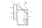
図1は、実施の形態1に係る背面投射型映像表示装置100の側面断面図である。
<
FIG. 1 is a side sectional view of a rear projection type
背面投射型映像表示装置100は、例えば、PC(Personal computer)等から入力された映像を表示する。
The rear projection type
図1を参照して、背面投射型映像表示装置100は、投射ユニット1と、反射鏡2と、スクリーンユニット3と、キャビネット4とを備える。
With reference to FIG. 1, a rear projection type
キャビネット4は、各種の構成要素を収容する筐体である。なお、図1では、図の簡略化のために、反射鏡2が、キャビネット4の外部に突き出るように示される。しかしながら、実際には、反射鏡2は、キャビネット4内に収容される。
The
投射ユニット1は、映像(映像光)を投射する。反射鏡2は、投射ユニット1から出力された映像(映像光)を光路途中で折り返す。これにより、背面投射型映像表示装置100(製品)の奥行きを短くする。反射鏡2は、筐体としてのキャビネット4内に配置される。
The
スクリーンユニット3は、透過型スクリーン3aを有する。透過型スクリーン3aは、投射ユニット1からの映像を結像する。スクリーンユニット3は、背面投射型映像表示装置100において、ユーザが映像を視聴する側に配置される。
The
図1において、光路5aは投射ユニット1から出力される映像光の中心部の光路である。光路5bは、投射ユニット1から出力される映像光の上部の光路である。光路5cは、投射ユニット1から出力される映像光の下部の光路である。
In FIG. 1, an
背面投射型映像表示装置100は、投射ユニット1から出力された映像(映像光)を、背面よりスクリーンユニット3(透過型スクリーン3a)に投射する。すなわち、背面投射型映像表示装置100では、スクリーンユニット3の背面より映像が投射される。
The rear projection type
この構成において、反射鏡2を介さず、直接、映像光を、スクリーンユニット3に投射する構成にした場合、背面投射型映像表示装置100(製品)の奥行きが大きくなる。そのため、キャビネット4の内部において一定の角度で取り付けられている反射鏡2で映像光を反射させて折り返す構成とすることにより、製品の奥行きを薄くする。
In this configuration, when the image light is directly projected onto the
つまり、投射ユニット1により、パソコン等から入力された映像(映像光)は、キャビネット4の任意の位置に配置された反射鏡2で反射され、スクリーンユニット3(透過型スクリーン3a)に結像する。
That is, the video (video light) input from the personal computer or the like by the
なお、一般的に、投射ユニット1は、スクリーンユニット3(透過型スクリーン3a)の下端より下部に配置される。なお、図1では、図の簡略化のため、投射ユニット1の一部がスクリーンユニット3の下端より上部にあるように示される。しかしながら、実際には、投射ユニット1は、スクリーンユニット3(透過型スクリーン3a)の下端より下部に配置される。そのため、そのため、キャビネット4の外形状は、スクリーンユニット3の下に突起がある構造となる。
In general, the
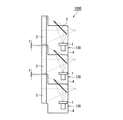
図2は、複数の背面投射型映像表示装置100を用いて構成された大画面表示システム1000の斜視図である。大画面表示システム1000は、例えば、映像のデジタル化に伴う高精細な映像を表示する。
FIG. 2 is a perspective view of a large
図3は、大画面表示システム1000の側面断面図である。
FIG. 3 is a side sectional view of the large
図2および図3を参照して、大画面表示システム1000は、一例として、9台の背面投射型映像表示装置100が、3行3列に並べられて構成される。なお、大画面表示システム1000を構成する背面投射型映像表示装置100の数は、9に限定されず、例えば、4,8,16等であってもよい。
Referring to FIGS. 2 and 3, as an example, large
隣接する2つの透過型スクリーン3aの隙間が、目地幅である。目地幅xは、左右(横)方向に隣接する2つの透過型スクリーン3aの隙間である。目地幅yは、上下(縦)方向に隣接する2つの透過型スクリーン3aの隙間である。
A gap between two
ここで、左右方向とは、大画面表示システム1000を設置する床等の面に対し平行な方向である。また、上下方向とは、大画面表示システム1000を設置する床等の面に対し垂直な方向である。以下においては、左右方向を、水平方向と表記する場合がある。また、以下においては、上下方向を、垂直方向と表記する場合がある。
Here, the left-right direction is a direction parallel to a surface such as a floor on which the large
図4は、大画面表示システム1000を構成する各背面投射型映像表示装置100の斜視図である。
FIG. 4 is a perspective view of each rear projection type
キャビネット4は、フレーム構造により構成されているとする。キャビネット4の左右方向の左端および右端の両端には、側面8aが設けられる。側面8aは、キャビネット4の左右方向の長さと同じ長さのフレーム8bによって各コーナーで固定される。これにより、立方体形状のキャビネット4が構成される。すなわち、キャビネット4は、投射ユニット1を収容するスペースを有する。キャビネット4の形状は、各背面投射型映像表示装置100を上下方向に積む際、上下の背面投射型映像表示装置100と干渉しないような形状になっている。
The
また、キャビネット4は、フレーム8cを含む。フレーム8cは、キャビネット4の前面側に設けられる。
The
図5は、スクリーンユニット3の側面図である。
FIG. 5 is a side view of the
図4および図5に示すように、スクリーンユニット3の上端および下端には、フレーム8gが設けられる。スクリーンユニット3の左端および右端には、フレーム8fが設けられる。
As shown in FIGS. 4 and 5, frames 8 g are provided at the upper and lower ends of the
スクリーンユニット3の透過型スクリーン3aは、2枚の樹脂製板材から構成される。透過型スクリーン3aは、例えば、レンチキュラーレンズ9aとフレネルレンズ9bとから構成される。
The
フレーム8f,8gは、レンチキュラーレンズ9aおよびフレネルレンズ9bの4辺を取り囲むように設けられる。
The
スクリーンユニット3は、キャビネット4のフレーム8cと接触する位置に固定される。
The
また、スクリーンユニット3は、当該スクリーンユニット3が移動自在なように、キャビネット4に取り付けられる(組み合う)。すなわち、スクリーンユニット3およびキャビネット4は、1つのユニットとなっている。スクリーンユニット3と、キャビネット4とは脱着可能な構造である。
The
なお、本実施の形態では、キャビネット4およびスクリーンユニット3は、フレーム構造としたが、フレームの代わりに板金を用いてもよい。
In the present embodiment, the
なお、前述したように、複数の背面投射型映像表示装置を縦横に積み上げて構築された大画面表示システムにおいては、キャビネットの外形サイズに対しスクリーンを小さめにしておく必要がある。そのため、キャビネット4およびスクリーンユニット3(透過型スクリーン3a)の外形サイズは、それぞれの材料の線膨張係数より計算されたキャビネット4およびスクリーンユニット3(透過型スクリーン3a)の伸び量の差分の隙間を設けるためのサイズである。
Note that, as described above, in a large screen display system constructed by stacking a plurality of rear projection type video display devices vertically and horizontally, it is necessary to make the screen smaller than the external size of the cabinet. Therefore, the external size of the
図2および図3では、隣接する各背面投射型映像表示装置100(透過型スクリーン3a)において、前述したように、目地幅x,yを定義した。すなわち、目地幅xは、左右方向に隣接する2つの透過型スクリーン3aの隙間である。目地幅yは、上下方向に隣接する2つの透過型スクリーン3aの隙間である。
2 and 3, the joint widths x and y are defined as described above in each of the adjacent rear projection type video display devices 100 (
この場合、1台の背面投射型映像表示装置100における、キャビネット4およびスクリーンユニット3の外形サイズの差は、x,yの半分である必要がある。すなわち、1台の背面投射型映像表示装置100においては、目地幅x/2,y/2が必要である。
In this case, the difference in the external size of the
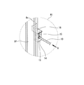
図6は、背面投射型映像表示装置100の背面側の斜視図である。なお、図6では、背面投射型映像表示装置100の内部を見やすくするために、キャビネット4の一部の面を透明にしている。
FIG. 6 is a perspective view of the rear side of the rear projection type
なお、図6には、領域R2内の構成が示されるが、実施の形態1に係る背面投射型映像表示装置100は、領域R2内の構成(後述の平面カム21、平面カム21に接続される長棒10等)は有さないとする。
6 shows the configuration in the region R2, but the rear projection
図7は、図6の領域R1の拡大図である。 FIG. 7 is an enlarged view of a region R1 in FIG.
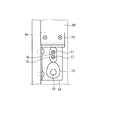
図8は、矢視Aから視た図7の構成を示す図である。 FIG. 8 is a diagram showing the configuration of FIG.
図6〜図8を参照して、背面投射型映像表示装置100は、さらに、長棒10と、保持部材11,12と、平面カム13と、部材14,18と、接触子15と、を備える。
With reference to FIGS. 6 to 8, the rear projection type
保持部材11,12は、キャビネット4の内面に固定される。具体的には、保持部材11は、キャビネット4の図示しない側面8aに固定される。保持部材12は、キャビネット4の図示しない背面に固定される。
The holding
部材14の形状は、L字状である。部材14は、ネジ等により、フレーム8cに固定される。
The shape of the
長棒10は、長い棒状の部材である。長棒10は、保持部材11,12により、回転自在に保持される。
The
平面カム13は、フレーム8cに固定された部材14のうち、透過型スクリーン3aに平行な面に接するように設けられる。平面カム13は、キャビネット4に収容される。具体的には、キャビネット4は、スクリーンユニット3と組み合わされて、平面カム13を覆う。平面カム13は、当該平面カム13の回転軸が偏芯された、板状のカムである。平面カム13は、部材14のうち、透過型スクリーン3aに平行な面に、回転自在に設けられる。
The
平面カム13の上部には、上下方向に移動可能な接触子15が設けられる。具体的には、接触子15には、上下方向に延在する長穴16が設けられる。接触子15は長穴16内の2本のネジ17により固定される。ネジ17は、段付き形状を有する。そのため、接触子15は上下方向に移動することができる。
A
接触子15の上部および下部の形状は、円弧状である。そのため、接触子15の上部は、部材18と点接触する。
The upper and lower shapes of the
ここで、スクリーンユニット3のフレーム8fの左右方向の断面の形状は、L字状である。すなわち、フレーム8fのうち、透過型スクリーン3a側の端部は、透過型スクリーン3aと平行である。
Here, the shape of the cross section in the left-right direction of the
部材18の形状は、L字状である。部材18は、接触子15の上下方向の移動により該接触子15から押圧を受ける位置に固定される。具体的には、部材18は、スクリーンユニット3のフレーム8fのうち、透過型スクリーン3aと平行な部分に固定される。
The shape of the
スクリーンユニット3がキャビネット4に取り付けられた(組み合わされた)状態では、部材18は、接触子15の上端に接触する。
When the
長棒10の一端は、平面カム13の回転軸に接続される。具体的には、長棒10の中心軸と平面カム13の回転軸とが一致する部分を溶接等にて固定されることにより、長棒10の一端と平面カム13とは接続される。これにより、長棒10が回転すると、平面カム13も同期して回転する。
One end of the
なお、長棒10の他端は、保持部材12を貫通して、キャビネット4の外側に突き出る。すなわち、長棒10は、キャビネット4の内側からキャビネット4の背面の外側まで延在する。これにより、作業者は、キャビネット4の外部から、平面カム13に接続される長棒10の他端を容易に掴むことができる。そのため、作業者は、長棒10(平面カム13)を回転させる操作を容易に行うことができる。すなわち、長棒10は、キャビネット4の外部からの操作により平面カム13を回転させるための回転機構である。
The other end of the
なお、平面カム13に接続される長棒10およびその他部材は、キャビネット4の左および右の側面8aの各々に配置されている。すなわち、キャビネット4の左の側面8aおよび右の側面8aには、それぞれ、2つの平面カム13が設けられている。すなわち、スクリーンユニット3の移動の調整には、左右2軸が用いられる。
The
スクリーンユニット3の上下方向の位置は、上記2つの平面カム13の回転状態によって設定される。以下においては、上記2つの平面カム13の一方を、平面カム13−1と表記する場合がある。また、以下においては、上記2つの平面カム13の他方を、平面カム13−2と表記する場合がある。
The vertical position of the
上記構成において、作業者が、キャビネット4の背面から、平面カム13に接続される長棒10の他端を掴んで、長棒10を回転させることにより、平面カム13が回転する。平面カム13の回転に応じて、平面カム13の上部に配置された接触子15が、長穴16の延在方向に沿って移動する。すなわち、接触子15は、平面カム13の回転に応じて、上下方向に移動する。つまり、接触子15は、平面カム13の回転に応じて上下方向に移動する部材である。
In the above configuration, when the operator grasps the other end of the
そして、接触子15の上下方向の移動に伴い、部材18は、接触子15から押圧を受ける。つまり、接触子15の上下方向の移動に伴い、上下方向において接触子15と接している部材18は上下方向に移動する。
The
これにより、部材18が固定されたスクリーンユニット3を上下方向に移動させることが可能となる。すなわち、部材18は、接触子15から押圧を受けることによりスクリーンユニット3を上下方向に移動させる。言い換えれば、平面カム13の回転に応じて、スクリーンユニット3は、上下方向に移動する。つまり、スクリーンユニット3は、上下並進する。すなわち、平面カム13は、該平面カム13が回転することによりスクリーンユニット3を所定方向(上下方向)に移動させるように設けられる。
Thereby, the
以上のようなスクリーンユニット3を上下方向に移動させる構成を、上下並進軸構造部(上下方向位置調整機構)ともいう。
The configuration for moving the
以上の構成により、作業者は、長棒10を利用して、背面投射型映像表示装置100のキャビネット4の背面から、背面投射型映像表示装置100の前方側に配置されたスクリーンユニット3の上下方向の位置調整を容易に行うことができる。
With the above configuration, the operator can use the
また、前述したように、接触子15の上部は、部材18と点接触する。そのため、平面カム13−1および平面カム13−2の各々の回転状態を異なるようにして、左右のスクリーンユニット3の左端部および右端部の上下移動量を変えることにより、スクリーンユニット3を回転移動させることも可能となる。
Further, as described above, the upper portion of the
以上の構成により、複数の背面投射型映像表示装置100を積み上げて構成する大画面表示システム1000において、各透過型スクリーン3a間の隙間を、任意のスクリーンユニット3単位でキャビネット4の背面から容易に調整することが可能となる。言い換えれば、大画面表示システム1000を構成する上で重要である、隣接する透過型スクリーン3a間の隙間を、各スクリーンユニット3単位で容易(簡単)に調整することができる。すなわち、スクリーンユニット3の位置を容易に調整することができる。
With the above configuration, in the large
なお、本実施の形態では、キャビネット4の背面からスクリーンユニット3を移動させる手段として平面カム13を使用した。なお、平面カム13の回転運動を往復運動に変換する手段として、他には、公さ軸歯車や食違い歯車等を使用する手法もある。しかしながら、これらは非常にコストが掛かってしまう欠点がある。
In the present embodiment, the
本実施の形態では、平面カム13を用いた上記構成により、最小部品点数でかつ低コストで背面投射型映像表示装置100のスクリーンユニット3の位置調整を実現することができる。
In the present embodiment, the above-described configuration using the
なお、平面カム13の形状は、接触子15の変位量sを縦軸とし、長棒10の回転角を横軸で示すカム線図と呼ばれるものより決定される。本実施の形態の平面カム13の外形形状は、スクリーンユニット3の上下方向の移動量(接触子15の変位量)が一定速度で、かつ長棒10を回す角度(平面カム13の回転角)に関らず、同じ変位量となるスムーズな外形形状とされる。
The shape of the
図9は、平面カム13の形状を説明するための図である。
FIG. 9 is a view for explaining the shape of the
図9(a)は、平面カム13のカム線図である。縦軸は、接触子15の変位量である。横軸は、長棒10の回転角である。
FIG. 9A is a cam diagram of the
図9(b)は、図9(a)のカム線図に従った平面カム13の形状を示す。カム線図を用いた場合、接触子15の変位量sを、一定角度で等分したそれぞれの値を、カムの回転軸中心から外形形状までの最小距離を半径とする円を等分割した半径線上にプロットする。プロットされた位置を曲線で結ぶことによって、平面カム13の形状が決定される。上記の形状の決定方法は、例えば、非特許文献(尾田十八、室津義定、「機械設計工学1[要素と設計]」改訂版、培風館)に示される。
FIG. 9B shows the shape of the
なお、スクリーンユニット3の移動量、つまり接触子15の変位量sは、スクリーンユニット3およびキャビネット4に使用される材料の線膨張係数により計算された目地幅以上の寸法が必要である。つまり、図2、図3および図4で示すように、スクリーンユニット3は、上下方向にそれぞれ、y/2変位する必要がある。
The moving amount of the
<実施の形態2>
実施の形態1では、長棒10および平面カム13を、キャビネット4の左右2軸で使用することによって、スクリーンユニット3を上下並進(上下移動)させる方法および回転させる構成を説明した。
<
In the first embodiment, the method of moving the
本実施の形態では、もう1軸、同様な長棒10および平面カム21を使用することでスクリーンユニット3の左右並進調整を実現できる構造について説明する。すなわち、本実施の形態に係る背面投射型映像表示装置100は、スクリーンユニット3を上下方向に移動させるための2個の平面カムと、スクリーンユニット3を左右方向に移動させるための1個の平面カムとを使用する。
In the present embodiment, a description will be given of a structure in which the left-right translational adjustment of the
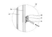
図10は、図6の領域R2の拡大図である。 FIG. 10 is an enlarged view of a region R2 in FIG.
図11は、矢視Bから視た図10の構成を示す図である。 FIG. 11 is a diagram showing the configuration of FIG.
図6、図10および図11を参照して、背面投射型映像表示装置100は、さらに、平面カム21と、部材22と、壁部23とを備える。
Referring to FIGS. 6, 10, and 11, rear projection type
部材22は、ネジ等により、図8の部材18と同様に、スクリーンユニット3のフレーム8fのうち、透過型スクリーン3aと平行な部分に固定される。
The
平面カム21は、スクリーンユニット3とキャビネット4とが組み合わされることにより形成される空間に設けられる。すなわち、キャビネット4は、スクリーンユニット3と組み合わされて、平面カム21を覆う。平面カム21の形状は、平面カム13の形状と同じである。平面カム21の外形の形状は、平面カム13の外形の形状と同じである。すなわち、平面カム21は、当該平面カム21の回転軸が偏芯された、板状のカムである。
The
平面カム21は、部材22の一方の面に、回転自在に設けられる。
The
壁部23は、スクリーンユニット3において、平面カム21の回転により該平面カム21から押圧を受ける位置に固定される。具体的には、壁部23は、部材22の左右方向の両側に固定される。すなわち、壁部23は、スクリーンユニット3に固定される。
In the
長棒10の一端は、平面カム21の回転軸に接続される。具体的には、長棒10の中心軸と平面カム21の回転軸とが一致する部分を溶接等にて固定されることにより、長棒10の一端と平面カム21とは接続される。これにより、長棒10が回転すると、平面カム21も同期して回転する。
One end of the
なお、平面カム21に接続される長棒10の他端は、保持部材12を貫通して、キャビネット4の外側に突き出る。すなわち、長棒10は、キャビネット4の内側からキャビネット4の背面の外側まで延在する。これにより、作業者は、キャビネット4の外部から、平面カム21に接続される長棒10の他端を容易に掴むことができる。
The other end of the
そのため、作業者は、長棒10(平面カム21)を回転させる操作を容易に行うことができる。すなわち、平面カム21に接続される長棒10は、キャビネット4の外部からの操作により平面カム21を回転させるための回転機構である。
Therefore, the operator can easily perform an operation of rotating the long bar 10 (plane cam 21). That is, the
図12は、平面カム21を所定角度だけ回転させた状態を示す図である。図12(a)は、平面カム21を反時計回りに、90度回転させた状態を示す図である。図12(b)は、平面カム21を時計回りに、90度回転させた状態を示す図である。
FIG. 12 is a view showing a state in which the
平面カム21が回転することにより、壁部23は平面カム21から押圧を受ける。当該押圧により、壁部23が固定された部材22(スクリーンユニット3)は左右方向に移動する。すなわち、壁部23は、該平面カム21から押圧を受けることによりスクリーンユニット3を左右方向に移動させる。
As the
例えば、図12(a)のように、左側の壁部23が平面カム21から押圧を受けることにより、部材22が固定されたスクリーンユニット3は、当該キャビネット4の背面からみて左方向に移動する。また、図12(b)のように、右側の壁部23が平面カム21から押圧を受けることにより、部材22が固定されたスクリーンユニット3は、当該キャビネット4の背面からみて右方向に移動する。
For example, as shown in FIG. 12A, when the
つまり、スクリーンユニット3のフレーム8fに固定された部材22が左右方向に移動することにより、スクリーンユニット3を左右方向に移動させることが可能となる。以上の構成により、平面カム21は、該平面カム21が回転することによりスクリーンユニット3を所定方向(左右方向)に移動させるように設けられる。
That is, the
前述したように、平面カム21の外形の形状は、平面カム13の外形の形状と同じである。具体的には、平面カム21の外形の形状は、当該平面カム21が反時計回りに回転した場合、キャビネット4の背面より見てスクリーンユニット3が左側に移動する形状である。また、平面カム21の外形の形状は、当該平面カム21が時計回りに回転した場合、キャビネット4の背面より見てスクリーンユニット3が右側に移動する形状である。
As described above, the outer shape of the
以上のようなスクリーンユニット3を左右方向に移動させる構成を、左右並進軸構造部(左右方向位置調整機構)ともいう。なお、スクリーンユニット3は、図2および図4で示すように、左右方向にそれぞれ、x/2変位する必要がある。
The configuration for moving the
本実施の形態は、背面投射型映像表示装置100は、実施の形態1で説明した、平面カム13による、スクリーンユニット3を上下移動または回転させる機構も有している。
In the present embodiment, the rear projection
前述したように、接触子15の上部は、部材18と点接触する。そのため、部材18(スクリーンユニット3)が、平面カム21の回転に応じて左右方向に併進移動しても、接触子15の上下位置は変化せずに、部材18のみを移動させることができる。
As described above, the upper portion of the
すなわち、本実施の形態の背面投射型映像表示装置100は、スクリーンユニット3の上下方向および左右方向の移動を同時に実現できる構造を有する。このような構成の背面投射型映像表示装置100は、実施の形態1と同様な効果を奏する。すなわち、作業者は、長棒10を利用して、背面投射型映像表示装置100のキャビネット4の背面から、スクリーンユニット3の上下方向および左右方向の位置調整を容易に行うことができる。すなわち、スクリーンユニット3の位置を容易に調整することができる。
That is, the rear projection type
なお、本実施の形態の背面投射型映像表示装置100は、図6の領域R1内の構成(平面カム13、平面カム13に接続される長棒10等)は有さないとしてもよい。この場合、背面投射型映像表示装置100は、スクリーンユニット3を上下方向に移動させる構成は有さず、スクリーンユニット3を左右方向に移動させる構成を有する。
Note that the rear projection type
<実施の形態2の変形例1>
実施の形態2の変形例1では、平面カム13,21の回転角度を所定角度に制限するための構成について説明する。
<
In the first modification of the second embodiment, a configuration for limiting the rotation angle of the
図13は、実施の形態2の変形例1に係る平面カム13の動作を説明するための図である。図13に示すように、実施の形態2の変形例1に係る平面カム13には、突起部19が形成される。
FIG. 13 is a view for explaining the operation of the
実施の形態2の変形例1に係る背面投射型映像表示装置100は、さらに、平面カム13の回転時に突起部19と当接し、平面カム13の回転角度を所定角度に制限するための壁部20を備える。
The rear projection type
具体的には、壁部20は、部材14の左端および右端に固定される。
Specifically, the
図13(a)は、突起部19が右側の壁部20と当接することにより、平面カム13の反時計周りの回転を制限している状態を示す。図13(b)は、図13(a)の平面カムが時計回りに90度回転した状態を示す。図13(c)は、突起部19が左側の壁部20と当接することにより、平面カム13の時計周りの回転を制限している状態を示す。以上の構成により、平面カム13が永遠に回り続けることを防ぐことができる。
FIG. 13A shows a state in which the counterclockwise rotation of the
図13では、上下並進軸における平面カム13の回転を制限する構成を示したが、平面カム21を利用した左右併進軸に対しても上記と同様な構成の壁部を設けてもよい。この場合、図13と同様に、平面カム21には、突起部19が形成される。この場合、背面投射型映像表示装置100は、さらに、平面カム21の回転時に突起部19と当接し、平面カム21の回転角度を所定角度に制限するための壁部を備える。
Although FIG. 13 shows a configuration that restricts the rotation of the
以上説明した構成により、実施の形態2の変形例1では、平面カム13,21が永遠に回り続けることを防ぐことができる。これにより、スクリーンユニット3の上下位置および左右位置を調整する際、調整幅の最大位置を容易に把握することができる。そのため、スクリーンユニット3の調整性をよくすることができる。
With the configuration described above, in the first modification of the second embodiment, the
<実施の形態2の変形例2>
前述において、スクリーンユニット3を、上下方向に移動させる構成、左右方向に移動させる構成、回転させる構成を説明した。複数の背面投射型映像表示装置100を用いて大画面表示システム1000を構成した場合、大画面表示システム1000の運用後に、あるスクリーンユニット3をキャビネット4から取り外し、再度、スクリーンユニット3をキャビネット4に取り付けるといった作業が必要になる場合がある。当該作業が必要な場合は、例えば、スクリーンユニット3(透過型スクリーン3a)の表面に傷がついた場合である。また、当該作業が必要な場合は、例えば、スクリーンユニット3の内部の埃を掃除する場合である。
<
In the above description, the configuration in which the
その際、上記実施の形態の構成を有する平面カムが、所定位置に固定され、回転できない状態を維持している場合、再度、スクリーンユニット3をキャビネット4に取り付ける際、当該スクリーンユニット3を取り外した位置に必ずスクリーンユニット3を配置する必要がある。この場合、スクリーンユニット3の取り付けが、作業的に非常に難しくなり慎重な作業となる。
At that time, when the flat cam having the configuration of the above embodiment is fixed at a predetermined position and maintains a state where it cannot rotate, the
ここで、例えば、大画面表示システム1000において、あるスクリーンユニット3自体を交換するとき、交換用のスクリーンユニット3の外形サイズが、交換前のスクリーンユニット3より少し大きいとする。この場合、スクリーンユニット3を取り外したキャビネット4の周囲にスクリーンユニット3が既に配置されているため、大画面表示システム1000内に、交換用のスクリーンユニット3を組みつけられなくなる可能性がある。
Here, for example, when a
そこで、ある背面投射型映像表示装置100のスクリーンユニット3をキャビネット4から取り外した際に、平面カムの固定位置が、毎回リセットされるようにする必要がある。
Therefore, when the
具体的には、例えば、背面投射型映像表示装置100のスクリーンユニット3をキャビネット4から取り外すことにより、平面カム13に加わる力がほとんどない場合、平面カム13の一部の位置が所定位置になるよう、平面カム13に重りを設ける。すなわち、平面カム13には、該平面カム13に加わる力がほとんどなく、該平面カム13が回転可能な状態である場合、平面カム13の一部の位置が所定位置になるよう、該平面カム13を回転させるための重り24が設けられる。
Specifically, for example, when there is almost no force applied to the
図14は、重り24を設けた平面カム13の動作を説明するための図である。
FIG. 14 is a view for explaining the operation of the
平面カム13は、スクリーンユニット3を上下方向に移動させるためのカムである。当該平面カム13の一部に重り24を設ける。重り24は、平面カム13が回転可能な状態である場合、重り24の作用により、平面カム13の状態が図14(a)に示す状態になるような位置に設けられる。
The
上記構成により、キャビネット4にスクリーンユニット3が取り付けられていない状態では、自然に平面カム13が図14(a)の状態になる。つまり、キャビネット4にスクリーンユニット3が取り付けられていない場合、スクリーンユニット3の位置が、当該スクリーンユニット3が上下方向に移動可能な範囲のうち、最も下の位置になる。
With the above configuration, in a state where the
なお、実施の形態2の変形例2における平面カム13の形状は、重り24によって平面カム13の位置が、自然に、所定の位置に戻されるための形状とする必要がある。すなわち、平面カム13の状態が、図14(a)に示す状態である場合、スクリーンユニット3の位置が、当該スクリーンユニット3が上下方向に移動可能な範囲のうち、最も下の位置になるような形状とする必要がある。
It should be noted that the shape of the
図14(b)および図14(c)は、キャビネット4にスクリーンユニット3が取り付けられている状態において、平面カム13が、前述の長棒10の操作により、所定の位置に固定されている状態を示す。
14 (b) and 14 (c) show a state in which the
なお、スクリーンユニット3を左右方向に移動させるための平面カム21については、スクリーンユニット3が、キャビネット4の左右方向の中心位置になるよう、平面カム21が自然に回転するための箇所に重り24を設ける。すなわち、平面カム21には、該平面カム21に加わる力がほとんどなく、該平面カム21が回転可能な状態である場合、平面カム21の一部の位置が所定位置になるよう、該平面カム21を回転させるための重り24が設けられる。
As for the
以上の構成により、キャビネット4にスクリーンユニット3が取り付けられていない場合、大画面表示システム1000における各背面投射型映像表示装置100は、常に、スクリーンユニット3を、最も下側の位置で、且つ、左右方向の中心位置に取り付けられる状態となる。
With the above configuration, when the
これにより、スクリーンユニット3を取り付けるための箇所に隣接するスクリーンユニット3の位置に関らず、再度、取り付け予定のスクリーンユニット3を、容易にキャビネット4に固定することが可能となる。
Thereby, it becomes possible to easily fix the
なお、上記説明では、各平面カムが、意図する方向に自然に回転するように、平面カムに重りを設ける構成としたが、この構成に限定されない。例えば、重りを使用せずに、平面カムの形状のみで、重り24が設けられた上記平面カムと同様な機能を有するようにしてもよい。すなわち、平面カムは、平面カムが回転可能な状態である場合、平面カムの一部の位置が所定位置になるよう、該平面カムを回転させる形状を有するようにしてもよい。当該平面カムは、平面カム13,21である。
In the above description, the weight is provided on the planar cam so that each planar cam rotates naturally in the intended direction, but the present invention is not limited to this configuration. For example, without using a weight, only the shape of the planar cam may be used, and the same function as the planar cam provided with the
例えば、平面カムの形状をいびつな形にすることで平面カムの重心位置を偏心させ、重りが設けられているのと同様な機能を有するようにしてもよい。また、例えば、平面カムの厚みを不均一にすることで平面カムの重心位置を偏心させ、重りが設けられているのと同様な機能を有するようにしてもよい。 For example, the shape of the planar cam may be irregular, thereby decentering the position of the center of gravity of the planar cam and having the same function as that provided with a weight. Further, for example, the center of gravity of the planar cam may be decentered by making the thickness of the planar cam non-uniform so as to have a function similar to that provided with a weight.
また、重りを使用せずに、引っ張りばね等を用いて、常に平面カムもしくは長棒に張力を掛けることで、スクリーンユニット3がキャビネット4に取り付けられていない場合、自然に平面カムが回転するような構成としてもよい。この場合、平面カムには、平面カムが回転可能な状態である場合、平面カムの一部の位置が所定位置になるよう、該平面カムを回転させるばねが取り付けられる。当該平面カムは、平面カム13,21である。
In addition, when a
<実施の形態2の変形例3>
複数の背面投射型映像表示装置100を用いた大画面表示システム1000において、スクリーンユニット3を固定、位置調整する場合は、大画面表示システム1000の設置時のみである。なお、稀に、スクリーンユニット3を交換することはあるが、基本的に、スクリーンユニット3の位置調整等は、製品生涯で1度だけである。
<
In the large
上記実施の形態およびその変形例において、キャビネット4の背面から平面カム13,21を回転させる手段として、長棒10を用いる構成を説明した。しかしながら、製品生涯で1度のために、長棒10を各背面投射型映像表示装置1台当たりに3本配置することは、費用的に無駄である。
In the said embodiment and its modification, the structure which uses the
実施の形態2の変形例3では、前述の長棒10の代わりに、図15に示すボルト25を使用する。ボルト25は、キャビネット4の内部に配置される。すなわち、ボルト25は、キャビネット4に収容される。ボルト25の長さは、平面カム13,21を取り付けるために必要な最低限の長さである。
In the third modification of the second embodiment, a
ボルト25は、工具26により、平面カムを回転させるように該平面カムに接続される。当該平面カムは、平面カム13,21である。工具26は、キャビネット4の背面の外側からボルト25までの長さを有する専用の工具である。
The
具体的には、各ボルト25の一端は、長棒10と同様に、平面カム13,21の回転軸に接続される。
Specifically, one end of each
作業者は、キャビネット4の背面から突き出た工具26の端部を握って、当該工具26(ボルト25)を回転させることにより、実施の形態1,2と同様に、平面カム13,21を回転させることができる。これにより、スクリーンユニット3の位置調整を容易に行うことができる。すなわち、ボルト25は、キャビネット4の外部からの操作により平面カムを回転させるための回転機構である。当該平面カムは、平面カム13,21である。
The operator rotates the
例えば、ボルト25のボルト頭の形状が六角形状であるとする。この場合、工具26は、六角形状のボルト25を回すことができる工具とする。これにより、各背面投射型映像表示装置100に設けられる平面カムの中心軸の棒の長さや、ボルト25の長さを短くすることができる。その結果、経済的なスクリーンユニット3の位置調整機能を有した背面投射型映像表示装置100を提供することができる。
For example, it is assumed that the bolt head shape of the
<実施の形態2の変形例4>
実施の形態1,2およびその変形例において、キャビネット4の背面から平面カム13,21を回転させる構成を説明した。しかしながら、どの構成も、前面でスクリーンユニット3の位置を保持する人と、キャビネット4にスクリーンユニット3をネジ等で固定する人の最低二人以上の作業者が必要である。そこで、背面投射型映像表示装置100のスクリーンユニット3の位置調整を一人で作業できる構成手法について説明する。
<
In the first and second embodiments and the modifications thereof, the configuration in which the
図16は、実施の形態2の変形例4に係る背面投射型映像表示装置100の背面側の斜視図である。
FIG. 16 is a perspective view of the rear side of the rear projection type
図16を参照して、実施の形態2の変形例4に係る背面投射型映像表示装置100では、実施の形態2の変形例3に係る背面投射型映像表示装置100と比較して、工具26の代わりに電動モータ27を使用する点が異なる。実施の形態2の変形例4に係る背面投射型映像表示装置100のそれ以外の構成は、実施の形態2の変形例3に係る背面投射型映像表示装置100と同様なので詳細な説明は繰り返さない。
Referring to FIG. 16, the rear projection type
電動モータ27は、ボルト25を回転させるためのモータである。すなわち、電動モータ27は、平面カム13,21を回転させるための回転機構である。電動モータ27は、キャビネット4に収容される。
The
電動モータ27は、ボルト25を回転させるために、ボルト25の端部に取り付けられる。電動モータ27は、投射ユニット1から電力が供給され、モータの回転を制御される。
The
以上の構成により、作業者は、投射ユニット1から透過型スクリーン3aに投写された映像のメニューを見ながら、電動モータ27をスクリーンユニット3側より制御可能となる。したがって、一人の作業者で背面投射型映像表示装置100のスクリーンユニット3の位置調整を行うことができる。
With the above configuration, the operator can control the
<実施の形態2の変形例5>
実施の形態2の変形例4では、電動モータ27を各スクリーンユニット3の調整軸(ボルト25)に取り付けることで、背面投射型映像表示装置100のスクリーンユニット3の位置調整を、一人の作業者で行うことが可能な構成について説明した。しかしながら、この構成では、各背面投射型映像表示装置100に、3台の電動モータ27を設ける必要がある。実施の形態2の変形例3でも説明したように、製品生涯で1度だけの位置調整のために高価な電動モータ27を使用することは、背面投射型映像表示装置100の製造に過剰な費用が発生する。
<Modification 5 of
In the fourth modification of the second embodiment, the
図17は、実施の形態2の変形例5に係る背面投射型映像表示装置100の背面側の斜視図である。
FIG. 17 is a perspective view of the rear side of the rear projection type
図17を参照して、実施の形態2の変形例5に係る背面投射型映像表示装置100は、図6の背面投射型映像表示装置100の構成と同様である。
Referring to FIG. 17, rear projection type
本実施の形態の変形例5では、スクリーンユニット3の位置調整のときだけ、キャビネット4から突き出た長棒10の端部に、一時的に、冶工具としての電動モータ27を取り付ける。すなわち、長棒10には、該長棒10を回転させるための電動モータ27が一時的に取り付けられる。
In the modified example 5 of the present embodiment, only when the position of the
この構成により、実施の形態2の変形例4と同様、一人の作業者で背面投射型映像表示装置100のスクリーンユニット3の位置調整を行うことができる。
With this configuration, the position of the
<実施の形態2の変形例6>
図18は、実施の形態2の変形例6に係る背面投射型映像表示装置100の背面側の斜視図である。
<
FIG. 18 is a rear perspective view of the rear projection type
図18を参照して、実施の形態2の変形例6に係る背面投射型映像表示装置100は、実施の形態2の変形例3(図15)の背面投射型映像表示装置100と比較して、さらに、長棒28と、電動モータ27とを備える点が異なる。実施の形態2の変形例6に係る背面投射型映像表示装置100のそれ以外の構成は、実施の形態2の変形例3(図15)の背面投射型映像表示装置100と同様なので詳細な説明は繰り返さない。
Referring to FIG. 18, rear projection type
平面カム13,21の各々に接続されるボルト25には、該ボルト25を回転させるための長棒28が取り付けられる。長棒28は、キャビネット4の背面の外側から該ボルト25までの長さを有する。
A
キャビネット4から突き出た長棒10の端部には、該長棒28を回転させるための電動モータ27が取り付けられる。すなわち、長棒28には、該長棒28を回転させるための電動モータ27が取り付けられる。
An
この構成により、実施の形態2の変形例4と同様、一人の作業者で背面投射型映像表示装置100のスクリーンユニット3の位置調整を行うことができる。
With this configuration, the position of the
なお、本発明は、その発明の範囲内において、各実施の形態、実施の形態の変形例を自由に組み合わせたり、各実施の形態、実施の形態の変形例を適宜、変形、省略することが可能である。 It should be noted that within the scope of the invention, the present invention can be freely combined with each embodiment and modification of the embodiment, or can be appropriately modified and omitted with each embodiment and modification of the embodiment. Is possible.
本発明は、スクリーンユニットの位置を容易に調整することが可能な背面投射型映像表示装置として、利用することができる。 The present invention can be used as a rear projection type image display device capable of easily adjusting the position of the screen unit.
1 投射ユニット、2 反射鏡、3 スクリーンユニット、3a 透過型スクリーン、4 キャビネット、10,28 長棒、11,12 保持部材、13,21 平面カム、14,18,22 部材、15 接触子、19 突起部、20,23 壁部、24 重り、25 ボルト、26 工具、100 背面投射型映像表示装置、1000 大画面表示システム。
DESCRIPTION OF
Claims (13)
回転自在に設けられ、回転軸が偏芯された平面カムと、
前記スクリーンユニットと組み合わされて、前記平面カムを覆うキャビネットと、を備え、
前記平面カムは、該平面カムが回転することにより前記スクリーンユニットを所定方向に移動させるように設けられ、
前記背面投射型映像表示装置は、さらに、
前記キャビネットの外部からの操作により前記平面カムを回転させるための回転機構を備える
背面投射型映像表示装置。 A rear projection type image display device in which an image is projected from the back of the screen unit,
A flat cam provided rotatably and having an eccentric rotation shaft;
A cabinet that is combined with the screen unit and covers the flat cam;
The planar cam is provided to move the screen unit in a predetermined direction by rotating the planar cam,
The rear projection type image display device further includes:
A rear projection type image display device comprising a rotation mechanism for rotating the planar cam by an operation from outside the cabinet.
前記平面カムは複数設けられ、
複数の前記平面カムのうち第1平面カムは、前記スクリーンユニットを前記上下方向に移動させるように設けられ、
前記複数の平面カムのうち第2平面カムは、前記スクリーンユニットを前記左右方向に移動させるように設けられる
請求項1に記載の背面投射型映像表示装置。 The predetermined direction is a vertical direction or a horizontal direction,
A plurality of the planar cams are provided,
A first planar cam among the plurality of planar cams is provided to move the screen unit in the vertical direction,
The rear projection image display device according to claim 1, wherein a second flat cam among the plurality of flat cams is provided to move the screen unit in the left-right direction.
前記回転機構は、前記平面カムの回転軸に接続された長棒であり、
前記長棒は、前記キャビネットの内側から前記キャビネットの背面の外側まで延在する
請求項1または2に記載の背面投射型映像表示装置。 The predetermined direction is a vertical direction or a horizontal direction,
The rotating mechanism is a long bar connected to the rotating shaft of the planar cam;
The rear projection type image display device according to claim 1, wherein the long bar extends from the inside of the cabinet to the outside of the back surface of the cabinet.
請求項3に記載の背面投射型映像表示装置。 The rear projection type image display device according to claim 3, wherein an electric motor for rotating the long bar is temporarily attached to the long bar.
前記背面投射型映像表示装置は、さらに、
前記平面カムの回転に応じて上下方向に移動する第1部材と、
前記スクリーンユニットにおいて、前記第1部材の上下方向の移動により該第1部材から押圧を受ける位置に固定された第2部材と、を備え、
前記第2部材は、前記第1部材から押圧を受けることにより前記スクリーンユニットを前記上下方向に移動させる
請求項1〜4のいずれか1項に記載の背面投射型映像表示装置。 The predetermined direction is a vertical direction,
The rear projection type image display device further includes:
A first member that moves up and down in response to rotation of the planar cam;
In the screen unit, comprising: a second member fixed at a position to receive pressure from the first member by movement of the first member in the vertical direction;
The rear projection type image display device according to any one of claims 1 to 4, wherein the second member moves the screen unit in the up-down direction by receiving a pressure from the first member.
前記背面投射型映像表示装置は、さらに、
前記スクリーンユニットにおいて、前記平面カムの回転により該平面カムから押圧を受ける位置に固定される第1壁部を備え、
前記第1壁部は、該平面カムから押圧を受けることにより前記スクリーンユニットを前記左右方向に移動させる
請求項1〜5のいずれか1項に記載の背面投射型映像表示装置。 The predetermined direction is a left-right direction,
The rear projection type image display device further includes:
In the screen unit, the first wall portion fixed to a position to receive pressure from the flat cam by the rotation of the flat cam,
The rear projection type image display device according to claim 1, wherein the first wall portion moves the screen unit in the left-right direction by receiving pressure from the flat cam.
前記背面投射型映像表示装置は、さらに、
前記平面カムの回転時に前記突起部と当接し、前記平面カムの回転角度を所定角度に制限するための第2壁部を備える
請求項1〜6のいずれか1項に記載の背面投射型映像表示装置。 A protrusion is formed on the planar cam,
The rear projection type image display device further includes:
The rear projection type image according to any one of claims 1 to 6, further comprising a second wall portion that comes into contact with the protrusion during rotation of the flat cam and limits a rotation angle of the flat cam to a predetermined angle. Display device.
請求項1〜7のいずれか1項に記載の背面投射型映像表示装置。 The planar cam is provided with a weight for rotating the planar cam so that a part of the planar cam becomes a predetermined position when the planar cam is in a rotatable state. The rear projection type image display device according to any one of the above.
請求項1〜7のいずれか1項に記載の背面投射型映像表示装置。 The planar cam has a shape for rotating the planar cam so that a part of the planar cam is in a predetermined position when the planar cam is rotatable. The rear projection type image display device according to item.
請求項1〜7のいずれか1項に記載の背面投射型映像表示装置。 The spring that rotates the planar cam is attached to the planar cam so that a part of the planar cam is in a predetermined position when the planar cam is rotatable. The rear projection type image display device according to claim 1.
前記ボルトは、前記キャビネットの背面の外側から前記ボルトまでの長さを有する工具により、前記平面カムを回転させるように該平面カムに接続される
請求項1,2,5〜10のいずれか1項に記載の背面投射型映像表示装置。 The rotation mechanism is a bolt accommodated in the cabinet,
The said bolt is connected to this plane cam so that the said plane cam may be rotated with the tool which has the length from the outer side of the back surface of the said cabinet to the said bolt. The rear projection type image display device according to item.
請求項1,2,5〜10のいずれか1項に記載の背面投射型映像表示装置。 The rear projection type image display device according to claim 1, wherein the rotation mechanism is an electric motor that is housed in the cabinet and rotates the planar cam.
前記ボルトは、前記平面カムの回転軸に接続され、
前記ボルトには、前記キャビネットの背面の外側から該ボルトまでの長さを有し、該ボルトを回転させるための長棒が取り付けられ、
前記長棒には、該長棒を回転させるための電動モータが取り付けられる
請求項1,2,5〜10のいずれか1項に記載の背面投射型映像表示装置。 The rotation mechanism is a bolt accommodated in the cabinet,
The bolt is connected to a rotating shaft of the planar cam;
The bolt has a length from the outside of the back of the cabinet to the bolt, and is attached with a long bar for rotating the bolt,
The rear projection type image display device according to claim 1, wherein an electric motor for rotating the long bar is attached to the long bar.
Priority Applications (1)
| Application Number | Priority Date | Filing Date | Title |
|---|---|---|---|
| JP2012069149A JP2013200465A (en) | 2012-03-26 | 2012-03-26 | Rear projection type video display device |
Applications Claiming Priority (1)
| Application Number | Priority Date | Filing Date | Title |
|---|---|---|---|
| JP2012069149A JP2013200465A (en) | 2012-03-26 | 2012-03-26 | Rear projection type video display device |
Publications (1)
| Publication Number | Publication Date |
|---|---|
| JP2013200465A true JP2013200465A (en) | 2013-10-03 |
Family
ID=49520749
Family Applications (1)
| Application Number | Title | Priority Date | Filing Date |
|---|---|---|---|
| JP2012069149A Pending JP2013200465A (en) | 2012-03-26 | 2012-03-26 | Rear projection type video display device |
Country Status (1)
| Country | Link |
|---|---|
| JP (1) | JP2013200465A (en) |
Cited By (3)
| Publication number | Priority date | Publication date | Assignee | Title |
|---|---|---|---|---|
| CN104455983A (en) * | 2014-11-28 | 2015-03-25 | 海信集团有限公司 | Screen levelness adjusting mechanism and projection display device |
| JP2016114878A (en) * | 2014-12-17 | 2016-06-23 | 三菱電機株式会社 | Projection type video display device |
| WO2020084750A1 (en) * | 2018-10-26 | 2020-04-30 | 三菱電機株式会社 | Rear-projection-type video display device |
-
2012
- 2012-03-26 JP JP2012069149A patent/JP2013200465A/en active Pending
Cited By (3)
| Publication number | Priority date | Publication date | Assignee | Title |
|---|---|---|---|---|
| CN104455983A (en) * | 2014-11-28 | 2015-03-25 | 海信集团有限公司 | Screen levelness adjusting mechanism and projection display device |
| JP2016114878A (en) * | 2014-12-17 | 2016-06-23 | 三菱電機株式会社 | Projection type video display device |
| WO2020084750A1 (en) * | 2018-10-26 | 2020-04-30 | 三菱電機株式会社 | Rear-projection-type video display device |
Similar Documents
| Publication | Publication Date | Title |
|---|---|---|
| KR101365218B1 (en) | 3-Dimensional Image Display Device And Displaying Method Using The Same | |
| US8031403B2 (en) | System and method for reducing visible speckle in a projection visual display system | |
| KR101755128B1 (en) | Virtual Reality Theater Structure | |
| WO2019155510A1 (en) | Multi-display system and video display device | |
| KR101175845B1 (en) | Projector fixing device | |
| US20040109145A1 (en) | Table type display device and an assembling method thereof | |
| JP4757935B2 (en) | Projection-type image display device | |
| JP2013200465A (en) | Rear projection type video display device | |
| JP2016538968A (en) | Simulation system for simulation of multi-screen screening system | |
| KR101803313B1 (en) | Simulation apparatus to experience earthquake | |
| US10356396B2 (en) | Exhibition device and video picture exhibition method | |
| CN108475005A (en) | The equipment of 3-D view and video for showing true environment | |
| JP2011175092A (en) | Projection display device | |
| JP2019129450A (en) | Multi-display system and simulator | |
| WO2010095486A1 (en) | Three-dimensional display device | |
| US20060109202A1 (en) | Multiple program and 3D display and 3D camera apparatus and process | |
| JP2012013818A (en) | Image display device | |
| JP2011164627A (en) | Projection type image display apparatus | |
| TW201131280A (en) | Projector | |
| WO2015070881A1 (en) | Display arranged for combining a physical object with one or more digital images | |
| JP3332129B2 (en) | Method of manufacturing transmission projection screen | |
| US20070103775A1 (en) | Projection display device and electronic apparatus with the same | |
| JP6215689B2 (en) | Packing structure | |
| Cruz‐Neira et al. | An affordable surround‐screen virtual reality display | |
| JP2007127924A (en) | Multi-screen display device |