JP2013201433A - Multi-chambered excimer or molecular fluorine gas discharge laser fluorine injection control - Google Patents
Multi-chambered excimer or molecular fluorine gas discharge laser fluorine injection control Download PDFInfo
- Publication number
- JP2013201433A JP2013201433A JP2013077923A JP2013077923A JP2013201433A JP 2013201433 A JP2013201433 A JP 2013201433A JP 2013077923 A JP2013077923 A JP 2013077923A JP 2013077923 A JP2013077923 A JP 2013077923A JP 2013201433 A JP2013201433 A JP 2013201433A
- Authority
- JP
- Japan
- Prior art keywords
- chamber
- halogen gas
- operating parameter
- oscillation
- amplification chamber
- Prior art date
- Legal status (The legal status is an assumption and is not a legal conclusion. Google has not performed a legal analysis and makes no representation as to the accuracy of the status listed.)
- Pending
Links
- 238000002347 injection Methods 0.000 title claims abstract description 108
- 239000007924 injection Substances 0.000 title claims abstract description 108
- YCKRFDGAMUMZLT-UHFFFAOYSA-N Fluorine atom Chemical compound [F] YCKRFDGAMUMZLT-UHFFFAOYSA-N 0.000 title claims abstract description 91
- 229910052731 fluorine Inorganic materials 0.000 title claims abstract description 91
- 239000011737 fluorine Substances 0.000 title claims abstract description 91
- PXGOKWXKJXAPGV-UHFFFAOYSA-N Fluorine Chemical compound FF PXGOKWXKJXAPGV-UHFFFAOYSA-N 0.000 title abstract description 6
- 229910052736 halogen Inorganic materials 0.000 claims abstract description 191
- 150000002367 halogens Chemical class 0.000 claims abstract description 191
- 238000000034 method Methods 0.000 claims abstract description 26
- 230000003321 amplification Effects 0.000 claims description 161
- 238000003199 nucleic acid amplification method Methods 0.000 claims description 161
- 230000010355 oscillation Effects 0.000 claims description 144
- 230000008859 change Effects 0.000 claims description 109
- 230000002596 correlated effect Effects 0.000 claims description 53
- 238000005259 measurement Methods 0.000 claims description 28
- 238000010304 firing Methods 0.000 claims description 9
- 239000000243 solution Substances 0.000 abstract 1
- 230000035945 sensitivity Effects 0.000 description 7
- 238000001802 infusion Methods 0.000 description 6
- 230000003287 optical effect Effects 0.000 description 3
- 230000000737 periodic effect Effects 0.000 description 3
- 238000001228 spectrum Methods 0.000 description 3
- 238000012935 Averaging Methods 0.000 description 2
- 239000003990 capacitor Substances 0.000 description 2
- 230000001419 dependent effect Effects 0.000 description 2
- 230000010354 integration Effects 0.000 description 2
- 239000004065 semiconductor Substances 0.000 description 2
- 230000002159 abnormal effect Effects 0.000 description 1
- 230000003044 adaptive effect Effects 0.000 description 1
- 230000008901 benefit Effects 0.000 description 1
- 230000006835 compression Effects 0.000 description 1
- 238000007906 compression Methods 0.000 description 1
- 230000001276 controlling effect Effects 0.000 description 1
- 230000000875 corresponding effect Effects 0.000 description 1
- 230000003111 delayed effect Effects 0.000 description 1
- 238000013461 design Methods 0.000 description 1
- 238000001514 detection method Methods 0.000 description 1
- 238000010586 diagram Methods 0.000 description 1
- 238000002474 experimental method Methods 0.000 description 1
- 239000007943 implant Substances 0.000 description 1
- 238000001459 lithography Methods 0.000 description 1
- 239000000203 mixture Substances 0.000 description 1
- 238000012986 modification Methods 0.000 description 1
- 230000004048 modification Effects 0.000 description 1
- 238000012545 processing Methods 0.000 description 1
- 230000004044 response Effects 0.000 description 1
- 238000005096 rolling process Methods 0.000 description 1
- 230000003595 spectral effect Effects 0.000 description 1
- 238000004611 spectroscopical analysis Methods 0.000 description 1
Images


Classifications
-
- H—ELECTRICITY
- H01—ELECTRIC ELEMENTS
- H01S—DEVICES USING THE PROCESS OF LIGHT AMPLIFICATION BY STIMULATED EMISSION OF RADIATION [LASER] TO AMPLIFY OR GENERATE LIGHT; DEVICES USING STIMULATED EMISSION OF ELECTROMAGNETIC RADIATION IN WAVE RANGES OTHER THAN OPTICAL
- H01S3/00—Lasers, i.e. devices using stimulated emission of electromagnetic radiation in the infrared, visible or ultraviolet wave range
- H01S3/02—Constructional details
- H01S3/03—Constructional details of gas laser discharge tubes
- H01S3/036—Means for obtaining or maintaining the desired gas pressure within the tube, e.g. by gettering, replenishing; Means for circulating the gas, e.g. for equalising the pressure within the tube
-
- H—ELECTRICITY
- H01—ELECTRIC ELEMENTS
- H01S—DEVICES USING THE PROCESS OF LIGHT AMPLIFICATION BY STIMULATED EMISSION OF RADIATION [LASER] TO AMPLIFY OR GENERATE LIGHT; DEVICES USING STIMULATED EMISSION OF ELECTROMAGNETIC RADIATION IN WAVE RANGES OTHER THAN OPTICAL
- H01S3/00—Lasers, i.e. devices using stimulated emission of electromagnetic radiation in the infrared, visible or ultraviolet wave range
- H01S3/14—Lasers, i.e. devices using stimulated emission of electromagnetic radiation in the infrared, visible or ultraviolet wave range characterised by the material used as the active medium
- H01S3/22—Gases
- H01S3/223—Gases the active gas being polyatomic, i.e. containing two or more atoms
- H01S3/225—Gases the active gas being polyatomic, i.e. containing two or more atoms comprising an excimer or exciplex
-
- H—ELECTRICITY
- H01—ELECTRIC ELEMENTS
- H01S—DEVICES USING THE PROCESS OF LIGHT AMPLIFICATION BY STIMULATED EMISSION OF RADIATION [LASER] TO AMPLIFY OR GENERATE LIGHT; DEVICES USING STIMULATED EMISSION OF ELECTROMAGNETIC RADIATION IN WAVE RANGES OTHER THAN OPTICAL
- H01S3/00—Lasers, i.e. devices using stimulated emission of electromagnetic radiation in the infrared, visible or ultraviolet wave range
- H01S3/23—Arrangements of two or more lasers not provided for in groups H01S3/02 - H01S3/22, e.g. tandem arrangements of separate active media
- H01S3/2366—Arrangements of two or more lasers not provided for in groups H01S3/02 - H01S3/22, e.g. tandem arrangements of separate active media comprising a gas as the active medium
-
- H—ELECTRICITY
- H01—ELECTRIC ELEMENTS
- H01S—DEVICES USING THE PROCESS OF LIGHT AMPLIFICATION BY STIMULATED EMISSION OF RADIATION [LASER] TO AMPLIFY OR GENERATE LIGHT; DEVICES USING STIMULATED EMISSION OF ELECTROMAGNETIC RADIATION IN WAVE RANGES OTHER THAN OPTICAL
- H01S3/00—Lasers, i.e. devices using stimulated emission of electromagnetic radiation in the infrared, visible or ultraviolet wave range
- H01S3/23—Arrangements of two or more lasers not provided for in groups H01S3/02 - H01S3/22, e.g. tandem arrangements of separate active media
- H01S3/2308—Amplifier arrangements, e.g. MOPA
- H01S3/2316—Cascaded amplifiers
Landscapes
- Physics & Mathematics (AREA)
- Electromagnetism (AREA)
- Engineering & Computer Science (AREA)
- Plasma & Fusion (AREA)
- Optics & Photonics (AREA)
- Lasers (AREA)
- Other Investigation Or Analysis Of Materials By Electrical Means (AREA)
Abstract
Description
本発明は、少なくとも1つの発振チャンバ及び少なくとも1つの増幅チャンバから成り、発振チャンバの出力が増幅チャンバ、例えば、主発振器電力増幅器(MOPA)構成フッ素注入コントローラ及び方法において増幅されるマルチチャンバエキシマ又は分子フッ素ガス放電レーザシステムに関する。
関連出願
本出願は、2004年9月29日出願の「マルチチャンバエキシマ又は分子フッ素ガス放電レーザフッ素注入制御」という名称の米国特許出願出願番号第10/953,100号に対する優先権を請求するものであり、これは、2003年7月30日出願の「2チャンバガス放電レーザのための制御システム」という名称の現在特許出願中の米国特許出願出願番号第10/631,349号、及び2003年1月31日出願の「ガス放電レーザのための自動ガス制御システム」という名称の米国特許出願出願番号第10/356,168号の一部継続出願であり、かつ2003年12月18日出願の「ガス放電MOPAレーザシステムの出力を制御する方法及び装置」という名称の米国特許出願出願番号第10/740,659号と、2004年2月27日出願の「帯域幅推定改善を目指した平面モデル」という名称の米国特許出願出願番号第10/789,328号と、「超小波長超狭帯域幅高電力レーザの光スペクトル出力の帯域幅を測定する方法及び装置」という名称の米国特許出願出願番号第10/609,223号と、1999年3月23日にDasに付与された「狭帯域エキシマレーザのための作動範囲を選択する方法」という名称の米国特許第5,887,014号とに関連しており、これらの各々は、本発明と共通の出願人に譲渡されており、この各々の開示内容は、本明細書において引用により組み込まれている。
The present invention comprises a multi-chamber excimer or molecule comprising at least one oscillation chamber and at least one amplification chamber, the output of the oscillation chamber being amplified in an amplification chamber, eg, a master oscillator power amplifier (MOPA) configuration fluorine injection controller and method The present invention relates to a fluorine gas discharge laser system.
RELATED APPLICATIONS This application claims the priority to U.S. Patent Application Serial No. 10 / 953,100, entitled "Multi-chamber excimer or molecular fluorine gas discharge Rezafu' containing injection control", filed Sep. 29, 2004 Which is currently filed US patent application Ser. No. 10 / 631,349, entitled “Control System for a Two Chamber Gas Discharge Laser”, filed Jul. 30, 2003, and 2003. This is a continuation-in-part of US patent application Ser. No. 10 / 356,168 entitled “Automatic Gas Control System for Gas Discharge Lasers” filed Jan. 31, and filed Dec. 18, 2003. US patent application Ser. No. 10 / 740,659 entitled “Method and Apparatus for Controlling the Output of a Gas Discharge MOPA Laser System”; US patent application Ser. No. 10 / 789,328, filed Feb. 27, 2004, entitled “Plane Model Aiming for Improved Bandwidth Estimation” and “Optical Spectrum of Ultra-Wavelength Ultra-Narrow Bandwidth High Power Laser” US patent application Ser. No. 10 / 609,223 entitled “Method and Apparatus for Measuring Bandwidth of Output” and “Operating Range for Narrow Band Excimer Lasers” granted to Das on March 23, 1999. Each of which is assigned to the same assignee as the present invention, the disclosure of each of which is incorporated herein by reference. It is incorporated by reference in the description.
上記で参照した現在特許出願中の出願は、マルチチャンバエキシマ又は分子フッ素ガス放電レーザシステムの別々のチャンバ内へのフッ素注入を各チャンバに対して別々に制御し、一方又は両方のチャンバに印加される電圧と、発振チャンバのエネルギ出力と、帯域幅とを表す信号を何らかの制御関数の一部として使用することを説明している。しかし、これらのシステムは有用であるが、このような制御を行うためのフッ素消費量に関連するレーザシステムパラメータをより良く利用するための改良が必要とされており、本出願は、これらの改良に関するものである。 The above-referenced, patent-pending applications are individually controlled for fluorine injection into separate chambers of a multi-chamber excimer or molecular fluorine gas discharge laser system and applied to one or both chambers. The use of signals representing the voltage, the energy output of the oscillation chamber, and the bandwidth as part of some control function. However, while these systems are useful, improvements are needed to better utilize laser system parameters related to fluorine consumption to perform such control, and the present application addresses these improvements. It is about.
フッ素注入制御システムを有し、少なくとも1つの発振チャンバと少なくとも1つの増幅チャンバとを含み、増幅チャンバが、この少なくとも1つのパワーチャンバ内で増幅される発振器出力レーザ光パルスを生成するマルチチャンバエキシマ又は分子ハロゲンガス放電レーザシステム及びその作動方法を開示し、これは、少なくとも1つの発振チャンバ及び少なくとも1つの増幅チャンバの一方の少なくとも第1の作動パラメータと少なくとも1つの発振チャンバ及び少なくとも1つの増幅チャンバの第2の作動パラメータの間の差とに基づいて、少なくとも1つの発振チャンバ及び増幅チャンバの一方において消費されたハロゲンガスの量を推定し、少なくとも1つの発振チャンバ及び少なくとも1つの増幅チャンバの他方の少なくとも第3の作動パラメータに基づいて、少なくとも1つの発振チャンバ及び少なくとも1つの増幅チャンバの他方において消費されたハロゲンガスの量を推定し、かつ少なくとも1つの発振チャンバにおける推定ハロゲンガス消費量と少なくとも1つの増幅チャンバにおけるハロゲンガス消費量とを表す出力を生成するハロゲンガス消費推定器と、フッ素消費推定器からの推定フッ素消費量出力と複数の重み付け注入決定判断を含むコスト関数とに基づいて、少なくとも1つの発振チャンバ及び少なくとも1つの増幅チャンバに対するハロゲンガス注入の量を判断するハロゲンガス注入コントローラとを含むことができる。第1の作動パラメータは、少なくとも1つの増幅チャンバの出力パルスの帯域幅パルスエネルギとすることができ、第2の作動パラメータは、少なくとも1つの発振チャンバ及び少なくとも1つの増幅チャンバにおけるガス放電の発射時間を表すことができ、第3の作動パラメータは、少なくとも1つの発振チャンバの出力パルスのエネルギとすることができる。ハロゲンガスは、フッ素とすることができる。 A multi-chamber excimer having a fluorine injection control system and including at least one oscillation chamber and at least one amplification chamber, wherein the amplification chamber generates an oscillator output laser light pulse that is amplified in the at least one power chamber; Disclosed is a molecular halogen gas discharge laser system and method of operation thereof, which includes at least a first operating parameter of one of at least one oscillation chamber and at least one amplification chamber and at least one oscillation chamber and at least one amplification chamber. And estimating the amount of halogen gas consumed in one of the at least one oscillation chamber and the amplification chamber based on the difference between the second operating parameters and the other of the at least one oscillation chamber and the at least one amplification chamber. at least Estimating the amount of halogen gas consumed in the other of the at least one oscillation chamber and the at least one amplification chamber based on three operating parameters, and estimating the halogen gas consumption and at least one amplification in the at least one oscillation chamber At least one based on a halogen gas consumption estimator that generates an output representative of the halogen gas consumption in the chamber, and an estimated fluorine consumption output from the fluorine consumption estimator and a cost function including a plurality of weighted injection decision decisions A halogen gas injection controller that determines an amount of halogen gas injection for the oscillation chamber and the at least one amplification chamber. The first operating parameter may be the bandwidth pulse energy of the output pulse of the at least one amplification chamber, and the second operating parameter is the firing time of the gas discharge in the at least one oscillation chamber and the at least one amplification chamber. And the third operating parameter may be the energy of the output pulse of at least one oscillation chamber. The halogen gas can be fluorine.
少なくとも1つの発振チャンバにおけるフッ素消費量の推定は、公式:

コスト関数は、
本方法及び装置は、少なくとも1つの発振チャンバ及び少なくとも1つの増幅チャンバの作動パラメータの間の差に基づいて少なくとも1つの発振器及び少なくとも1つの増幅チャンバの一方において消費されたハロゲンガスの量を推定し、少なくとも1つの発振チャンバ及び増幅チャンバの他方において消費されたハロゲンガスの量を推定し、かつ少なくとも1つの発振チャンバ及び少なくとも1つの増幅チャンバにおける推定ハロゲンガス消費量を表す出力を生成するハロゲンガス消費推定器を含むことができる。作動パラメータは、少なくとも1つの発振チャンバ及び少なくとも1つの増幅チャンバのそれぞれのものにおけるガス放電のタイミングとすることができる。本方法及び装置は、少なくとも1つの発振チャンバ及び少なくとも1つの増幅チャンバの一方において消費されたハロゲンガスの量を少なくとも1つの発振チャンバ及び少なくとも1つの増幅チャンバの他方の作動パラメータに基づいて推定し、少なくとも1つの発振チャンバ及び増幅チャンバの他方において消費されたハロゲンガスの量を推定し、かつ少なくとも1つの発振チャンバ及び少なくとも1つの増幅チャンバにおける推定ハロゲンガス消費量を表す出力を生成するハロゲンガス消費推定器を含むことができる。作動パラメータは、E95とすることができる。本方法及び装置は、少なくとも1つの発振チャンバにおけるハロゲンガス消費の量を示す少なくとも1つのパラメータと少なくとも1つの増幅チャンバにおけるハロゲンガス消費の量を示す少なくとも1つのパラメータとに基づいて、少なくとも1つの発振チャンバ及び少なくとも1つの増幅チャンバの各々において消費されたハロゲンガスの量を推定し、少なくとも1つの発振チャンバのハロゲンガス消費量を表す出力と少なくとも1つの増幅チャンバのハロゲンガス消費量を表す出力とを生成するハロゲンガス消費推定器を含むことができる。少なくとも1つの発振チャンバにおけるハロゲンガス消費量を示す少なくとも1つの作動パラメータは、少なくとも2つの作動パラメータトすることができ、その第1のパラメータは、少なくとも1つの発振チャンバ及び少なくとも1つの増幅チャンバの作動パラメータの差であり、その第2のパラメータは、少なくとも1つの増幅チャンバの作動パラメータであり、少なくとも1つの増幅チャンバにおけるハロゲンガス消費量を示す少なくとも1つの作動パラメータは、少なくとも2つの作動パラメータとすることができ、その1つは、少なくとも1つの発振チャンバの作動パラメータであり、その1つは、少なくとも1つの増幅チャンバの作動パラメータである。コスト関数は、より高い重み係数を有する別の重み付け注入決定判断が存在しない限り、少なくとも1つの発振チャンバにおけるハロゲンガス消費量の推定値が少なくとも1つの増幅チャンバにおけるハロゲンガス消費量の推定値を超えた場合に、ハロゲンガスを少なくとも1つの発振チャンバに注入する第1の重み係数を有する決定と、少なくとも1つの増幅チャンバにおけるハロゲンガス消費量の推定値が少なくとも1つの発振チャンバにおけるハロゲンガス消費量の推定値を超えた場合に、ハロゲンガスを少なくとも1つの増幅チャンバに注入する第2の重み係数を有する決定とを含むことができる。他の重み付け注入決定判断は、帯域幅が帯域幅の範囲内で高又は低で仕様外であるか否か、及び電圧が電圧の範囲内で高又は低で仕様外であるか否かの群、又は他のパラメータから選択することができる。ハロゲンガス消費量の推定は、発振チャンバ及び増幅チャンバのそれぞれのものにおけるハロゲンガス含有量の実験的に判断された変化に相関付けられた作動パラメータの測定された変化に基づくことができる。少なくとも1つの発振チャンバにおけるハロゲンガス消費量の推定は、少なくとも1つの発振チャンバにおけるハロゲンガス含有量の実験的に判断された変化に相関付けられた第1の作動パラメータの測定された変化と、少なくとも1つの発振チャンバにおけるハロゲンガス含有量の実験的に判断された変化に相関付けられた第2の作動パラメータの測定された変化とに基づいており、少なくとも1つの増幅チャンバにおけるハロゲンガス消費量の推定は、少なくとも1つの増幅チャンバにおけるハロゲンガス含有量の実験的に判断された変化に相関付けられた第3の作動パラメータの測定された変化と、少なくとも1つの増幅チャンバにおけるハロゲンガス含有量に実験的に判断された変化に相関付けられた第4の作動パラメータの測定された変化とに基づいている。ハロゲンガス消費量の推定は、発振チャンバ及び増幅チャンバのそれぞれのものにおけるハロゲンガス含有量の実験的に判断された変化に相関付けられた作動パラメータの測定された変化に基づくことができる。少なくとも1つの発振チャンバにおけるハロゲンガス消費量の推定は、少なくとも1つの発振チャンバにおけるハロゲンガス含有量の実験的に判断された変化に相関付けられた第1の作動パラメータの測定された変化と、少なくとも1つの発振チャンバにおけるハロゲンガス含有量の実験的に判断された変化に相関付けられた第2の作動パラメータの測定された変化とに基づくことができ、少なくとも1つの増幅チャンバにおけるハロゲンガス消費量の推定は、少なくとも1つの増幅チャンバにおけるハロゲンガス含有量の実験的に判断された変化に相関付けられた第3の作動パラメータの測定された変化と、少なくとも1つの増幅チャンバにおけるハロゲンガス含有量の実験的に判断された変化に相関付けられた第4の作動パラメータの測定された変化とに基づくことができる。ハロゲンガス消費量の推定は、発振チャンバ及び増幅チャンバのそれぞれのものにおけるハロゲンガス含有量の実験的に判断された変化に相関付けられた作動パラメータの測定された変化に基づくことができる。少なくとも1つの発振チャンバにおけるハロゲンガス消費量の推定は、少なくとも1つの発振チャンバにおけるハロゲンガス含有量の実験的に判断された変化に相関付けられた第1の作動パラメータの測定された変化と、少なくとも1つの発振チャンバにおけるハロゲンガス含有量の実験的に判断された変化に相関付けられた第2の作動パラメータの測定された変化とに基づくことができ、少なくとも1つの増幅チャンバにおけるハロゲンガス消費量の推定は、少なくとも1つの増幅チャンバにおけるハロゲンガス含有量の実験的に判断された変化に相関付けられた第3の作動パラメータの測定された変化と、少なくとも1つの増幅チャンバにおけるハロゲンガス含有量に実験的に判断された変化に相関付けられた第4の作動パラメータの測定された変化とに基づくことができる。 The method and apparatus estimate the amount of halogen gas consumed in one of the at least one oscillator and the at least one amplification chamber based on a difference between the operating parameters of the at least one oscillation chamber and the at least one amplification chamber. Halogen gas consumption that estimates the amount of halogen gas consumed in the other of the at least one oscillation chamber and amplification chamber and produces an output representative of the estimated halogen gas consumption in the at least one oscillation chamber and at least one amplification chamber An estimator can be included. The operating parameter may be the timing of gas discharge in each of the at least one oscillation chamber and the at least one amplification chamber. The method and apparatus estimate the amount of halogen gas consumed in one of the at least one oscillation chamber and the at least one amplification chamber based on the operating parameters of the other of the at least one oscillation chamber and the at least one amplification chamber; Halogen gas consumption estimation that estimates the amount of halogen gas consumed in the other of the at least one oscillation chamber and the amplification chamber and produces an output representative of the estimated halogen gas consumption in the at least one oscillation chamber and the at least one amplification chamber Can be included. The operating parameter may be E95. The method and apparatus includes at least one oscillation based on at least one parameter indicative of the amount of halogen gas consumption in the at least one oscillation chamber and at least one parameter indicative of the amount of halogen gas consumption in the at least one amplification chamber. Estimating the amount of halogen gas consumed in each of the chamber and at least one amplification chamber, and outputting an output representative of the halogen gas consumption of the at least one oscillation chamber and an output representative of the halogen gas consumption of the at least one amplification chamber. A halogen gas consumption estimator can be included. The at least one operating parameter indicative of halogen gas consumption in the at least one oscillation chamber can be at least two operating parameters, the first parameter being an operation of the at least one oscillation chamber and the at least one amplification chamber. A parameter difference, the second parameter being an operating parameter of at least one amplification chamber, and the at least one operating parameter indicative of halogen gas consumption in the at least one amplification chamber being at least two operating parameters One of which is an operating parameter of at least one oscillation chamber and one of which is an operating parameter of at least one amplification chamber. The cost function is such that the estimated halogen gas consumption in at least one oscillation chamber exceeds the estimated halogen gas consumption in at least one amplification chamber unless there is another weighted injection decision decision with a higher weighting factor. A determination having a first weighting factor for injecting the halogen gas into the at least one oscillation chamber and an estimate of the halogen gas consumption in the at least one amplification chamber is a value of the halogen gas consumption in the at least one oscillation chamber. A determination having a second weighting factor for injecting halogen gas into the at least one amplification chamber if the estimated value is exceeded. Other weighted injection decision decisions include whether the bandwidth is high or low within the bandwidth and out of specification, and whether the voltage is high or low within the voltage and out of specification. Or other parameters can be selected. The estimation of halogen gas consumption can be based on measured changes in operating parameters correlated to experimentally determined changes in halogen gas content in each of the oscillation chamber and amplification chamber. The estimation of the halogen gas consumption in the at least one oscillation chamber is at least a measured change in the first operating parameter correlated to an experimentally determined change in the halogen gas content in the at least one oscillation chamber. Estimating halogen gas consumption in at least one amplification chamber based on a measured change in the second operating parameter correlated to an experimentally determined change in halogen gas content in one oscillation chamber Experimentally measured the measured change in the third operating parameter correlated to the experimentally determined change in halogen gas content in the at least one amplification chamber and the halogen gas content in the at least one amplification chamber. Measurement of the fourth operating parameter correlated to the determined change in And it is based on the change and. The estimation of halogen gas consumption can be based on measured changes in operating parameters correlated to experimentally determined changes in halogen gas content in each of the oscillation chamber and amplification chamber. The estimation of the halogen gas consumption in the at least one oscillation chamber is at least a measured change in the first operating parameter correlated to an experimentally determined change in the halogen gas content in the at least one oscillation chamber. Based on a measured change in the second operating parameter correlated to an experimentally determined change in the halogen gas content in one oscillation chamber, the amount of halogen gas consumption in the at least one amplification chamber The estimation is based on a measured change in the third operating parameter correlated to an experimentally determined change in halogen gas content in the at least one amplification chamber and an experiment of halogen gas content in the at least one amplification chamber. Measurement of the fourth operating parameter correlated to the automatically determined change It may be based on the change and that is. The estimation of halogen gas consumption can be based on measured changes in operating parameters correlated to experimentally determined changes in halogen gas content in each of the oscillation chamber and amplification chamber. The estimation of the halogen gas consumption in the at least one oscillation chamber is at least a measured change in the first operating parameter correlated to an experimentally determined change in the halogen gas content in the at least one oscillation chamber. Based on a measured change in the second operating parameter correlated to an experimentally determined change in the halogen gas content in one oscillation chamber, the amount of halogen gas consumption in the at least one amplification chamber The estimation is based on a measured change in the third operating parameter correlated to an experimentally determined change in halogen gas content in the at least one amplification chamber and a halogen gas content in the at least one amplification chamber. Measurement of the fourth operating parameter correlated to the automatically determined change It may be based on the change and that is.
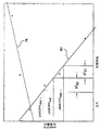
ここで図1を参照すると、レーザガス利得媒体を形成するマルチチャンバエキシマ又は分子ガス放電レーザガスにおいてガス放電を引き起こす電極間の放電間のタイミングの変化、例えばdtMOPAと、チャンバにおけるF2の量の変化、すなわち、チャンバ、例えば、本発明の実施形態の態様に従って有用な発振チャンバ(MO)及び増幅チャンバ(PA)におけるフッ素の消費の量の指示とに関する代表的なプロットを示している。これはまた、dtMOPAを何らかの基準値dtMOPAREFに戻すために求められる注入の量(ΔF2)を表し、これは、負の注入(すなわち、注入は不要)ΔF2(1)又は正の注入ΔF2(2)とすることができる。このプロットでは、F2含有量は、任意の単位で横軸上にあり、dtMOPAは、任意の単位で縦軸上にある。類似のプロットの作成は、他の作動パラメータの関係に対して、例えば、E95%又は単にE95としても公知である中心波長を中心とするスペクトルの中心波長の両側で含まれるエネルギのある一定のパーセント、例えば95%の積分によって測定された時の帯域幅と、チャンバに印加される電圧、例えば、各チャンバに対する各半導体パルス電力システム(SSPPM)の各圧縮ヘッドのピークコンデンサでの両方のチャンバに印加される共通電圧と、チャンバの1つ、例えば発振チャンバのエネルギ出力EMOとに対して行うことができる。 Referring now to FIG. 1, a change in timing between discharges that cause a gas discharge in a multi-chamber excimer or molecular gas discharge laser gas forming a laser gas gain medium, eg, dtMOPA and change in the amount of F 2 in the chamber, That is, a representative plot is shown for an indication of the amount of fluorine consumption in a chamber, eg, an oscillation chamber (MO) and an amplification chamber (PA) useful according to aspects of embodiments of the present invention. This also represents the amount of injection (ΔF 2 ) required to return dtMOPA to some reference value dtMOPA REF , which is either a negative injection (ie no injection required) ΔF 2 (1) or a positive injection ΔF 2 (2) . In this plot, the F 2 content is on the horizontal axis in arbitrary units, and dtMOPA is on the vertical axis in arbitrary units. The creation of a similar plot is a certain percentage of the energy contained on either side of the center wavelength of the spectrum centered around the center wavelength, also known as E95% or simply E95, for example, relative to other operating parameter relationships. For example, the bandwidth as measured by 95% integration and the voltage applied to the chamber, for example, applied to both chambers at the peak capacitor of each compression head of each semiconductor pulse power system (SSPPM) for each chamber a common voltage, one of the chambers can be carried out, for example with respect to the energy output E MO of the oscillation chamber.
好ましい実施形態は、主発振器電力増幅器マルチチャンバエキシマ又は分子フッ素ガス放電レーザシステム(MOPA)であるが、システムはまた、他の発振器/増幅器構成、例えば、単なる第1ステージの出力の誘導放出増幅と対照的に、例えば、電力発振器第1ステージが線狭窄化されておらず、増幅器第2ステージが発振器ステージ、例えば、増幅器として作用する不安定な発振器ステージである、例えば、主発振器電力発振器(MOPO)、電力発振器電力増幅器(POPA)、又は電力発振器電力発振器(POPO)構成などを有するように構成することができることが当業者によって理解されるであろう。また、このような構成の各々においては、線狭窄化の有無を問わず、第1の発振器ステージの出力は、発振器であるか否かを問わず、第2のステージで何らかの方法で増幅されることが理解されるであろう。特に反対であることを別段示さない限り、本明細書又は特許請求の範囲における主発振器ステージ又はチャンバ(MO)、及び/又は本明細書又は特許請求の範囲における電力増幅器ステージ又はチャンバ(PA)への言及は、増幅のためにあらゆる増幅器の第2のステージ又はチャンバ内へ出力を給送するあらゆる発振器の第1のステージ又はチャンバを包含するほど十分に広義であると考えるものとし、発振チャンバ又は発振器ステージという用語は、あらゆるこのような発振器ステージを包含するほど十分に広義であり、増幅器ステージ又はチャンバという用語は、あらゆるこのような増幅器ステージを包含するほど十分に広義である。 The preferred embodiment is a master oscillator power amplifier multi-chamber excimer or molecular fluorine gas discharge laser system (MOPA), but the system can also be used with other oscillator / amplifier configurations, eg, stimulated emission amplification of the output of the first stage only. In contrast, for example, the power oscillator first stage is not line constricted and the amplifier second stage is an oscillator stage, eg, an unstable oscillator stage acting as an amplifier, eg, a main oscillator power oscillator (MOPO) It will be appreciated by those skilled in the art that a power oscillator power amplifier (POPA), power oscillator power oscillator (POPO) configuration, etc. can be configured. In each of these configurations, the output of the first oscillator stage is amplified in some way in the second stage, whether or not it is an oscillator, regardless of whether or not the line is narrowed. It will be understood. Unless stated to the contrary, to the master oscillator stage or chamber (MO) in this specification or claims, and / or to the power amplifier stage or chamber (PA) in this specification or claims. Is considered to be broad enough to encompass the first stage or chamber of any oscillator that feeds the output into the second stage or chamber of any amplifier for amplification, The term oscillator stage is broad enough to encompass any such oscillator stage, and the term amplifier stage or chamber is broad enough to encompass any such amplifier stage.
あらゆるパラメータ又は作動パラメータの組合せを用いて、ρiで示す1つ又はそれよりも多くの調節可能な感度パラメータを通じていずれか又は両方のチャンバにおける消費フッ素を推定することができ、ここで、iは、組内のi番目の感度パラメータを示している。感度パラメータは、パラメータの1つ又はそれよりも多くの測定値のフィードバックを用いて調節することができる。感度ρiの初期値は、実験的に又は物理学に基づく原則を用いて決めることができる。図1は、本発明の実施形態の態様に従って有用である例えばMOチャンバとPAチャンバにおけるdtMOPAとF2濃度の一般的な感度プロットを示している。 Any parameter or combination of operating parameters can be used to estimate the fluorine consumed in either or both chambers through one or more adjustable sensitivity parameters, denoted by ρ i , where i is , Shows the i-th sensitivity parameter in the set. The sensitivity parameter can be adjusted using feedback of one or more measurements of the parameter. The initial value of sensitivity ρ i can be determined experimentally or using principles based on physics. FIG. 1 shows a general sensitivity plot of dtMOPA and F 2 concentrations, for example, in MO and PA chambers that are useful in accordance with aspects of embodiments of the present invention.
ここで図3を参照すると、例えば、フッ素消費推定器を含むことができるフッ素(F2)注入制御システム20を示すものであり、フッ素消費推定器は、例えば、パラメータの値と、同じ又は他のチャンバにおけるF2の消費量を示す及び/又はそれに相関付けられた例えば通常作動の何らかの望ましいレベルでの何らかの望ましい基準値との差を表すいくつかの入力信号、例えば帯域幅BW26、例えばE95、発振チャンバと増幅チャンバの間の放電タイミングdtMOPA、印加高電圧V30、及びチャンバ例えば発振チャンバのエネルギ出力Emo32を採用することができる。Δ値は、パラメータの実測値と何らかの望ましい基準値、例えばBWREFとの間の差を表すことが理解されるであろう。
Referring now to FIG. 3, there is shown a fluorine (F 2 )
フッ素消費推定器は、フッ素消費量(推定ΔF2)を表すこれらの入力を利用して、例えば、発振チャンバにおける推定フッ素消費量
本発明の実施形態の態様によれば、システム20は、何らかの期間にわたって、例えば30秒毎に、例えば何らかの選択基準値と比較して、フッ素消費量指示パラメータ、例えば、E95、dtMOPA、V、及びEMOの1つの変化を蓄積することができる。プロットから、例えば図1に示すように、図1のこれらの値E95、dtMOPA、V、及びEMOの各々のいずれかの所定の値に対して、例えばフッ素消費量とE95及びdtMOPAのプロットから取った値に対しては発振チャンバ、又は増幅チャンバのV及びEMOの変化に関するフッ素消費量に関するプロットに対しては増幅チャンバにおいて消費されるフッ素量の推定値を判断することができる。これらの値を何らかの方法でF2消費推定器22によって組み合わせて、発振チャンバ
2つの値がそれぞれのチャンバにおける推定フッ素消費量の計算に使用される場合、各このような変数に関する推定フッ素消費量は、それを何らかの信頼/重み付け係数αと関連付けることができ、等しくSNRによって影響を受けた信号に対しては、αを0.5とすることができ、一方、他方の信頼/重み付け係数(1−α)も、次に0.5、すなわち、2つの等しい重み付けとすることができる。しかし、1つの信号が例えば関連の値の測定において優れたSNRを有する時、より高いα、例えば、0.75を有することができ、他方の値(1−α)は、0.25になる。このようにして、2つ又はそれよりも多くのこのような信号を利用すると、各々が例えばE95、dtMOPA、V、及び/又はEMOに対する実際の値又はそれに対する値の変化に対するその感度において比較的ノイズを発生するものなどであったとしても、より信頼性の高い、例えばノイズが少ない信号(
従って、本発明の実施形態の態様によれば、
次に、これをそれぞれのチャンバにおけるF2の消費量の1つ又はそれよりも多くの他の推定値と組み合わせて、信頼値αを掛け、上述のように例えば、
図2はまた、例えば、到達が望まれない何らかの厳しい限界値の数パーセント以内とすることができる柔軟な限界値の存在を示している。主要な決定判断の1つが、例えば電圧又はdtMOPAがその柔軟な限界値に到達したので注入を行うべきであることを示す状況があると考えられる。コスト関数による決定判断重み係数は、例えば、ΔF2が一方又は他方のチャンバにおいてより大きいという指示よりも大きい、例えば、「prefPA INJ」に対するコスト関数に関して本明細書で説明するように、決定重み係数V>柔軟な限界値=10であろう。 FIG. 2 also shows the existence of a flexible limit that can be, for example, within a few percent of some severe limit that is not desired to be reached. There may be situations where one of the major decision decisions indicates that an injection should be made, for example, because the voltage or dtMOPA has reached its flexible limit. The decision decision weighting factor by the cost function is greater than, for example, an indication that ΔF 2 is greater in one or the other chamber, eg, as described herein with respect to the cost function for “prefPA INJ” V> soft limit value = 10.
コスト関数は、次に、例えば、最高の重み付け値を有するものが選択された判断とすることができる、例えば単に1組の重み付け決定判断とすることができる。例えば、この決定は、発振チャンバにおける推定消費量
従って、フッ素注入コントローラ24は、真であると共に最高の重み付けを有する決定判断に基づいて発振チャンバF2JNJMO50又は増幅チャンバF2INJPA60に注入する決定をする。例えば、等しく重み付けされる推定消費量値は、一方が真である、すなわち、他のより高い重み付け決定のいずれも真、すなわち、prefMO INJ(E95upper)=7、prefMO INJ(Vupper)=8、prefMO INJ(E95lower)=9、及び/又はprefMO INJ(Vlower)=10でない限り、
簡単に言えば、フッ素注入制御アルゴリズムは、例えば、フッ素含有量感受性でもあるMOチャンバ及びPAチャンバにおけるフッ素消費量推定に基づく何らかの選択作動帯域からレーザシステムが出たために、何らかの他のシステムパラメータに二重チャンバのそれぞれへの注入が必要でない限り、少なくとも線形に近い状態が2つの変化の間に存在するある一定の領域内でフッ素消費量によって綿密に追跡され、すなわち、Δ曲線、例えばΔE95/ΔF2曲線の傾きを使用して説明されることを本出願人が既に発見しているレーザ作動パラメータの値に基づくものである。消費量推定パラメータとしては、例えば、エネルギ(PAチャンバ)、エネルギ(シャッター)、エネルギ(スキャナ)、エネルギ(ウェーハ)、例えば、ウィンドウサイズにわたって定められる負荷サイクル、発射繰返し数、時間、あらゆる実測されたガス(フッ素を含む)濃度(MOチャンバ)、あらゆる実測されたガス(フッ素を含む)濃度(PAチャンバ)、圧力(MOチャンバ)、圧力(PAチャンバ)、温度(MOチャンバ)、及び温度(PAチャンバ)などを含むことができる。 Simply put, the fluorine injection control algorithm can be used to account for some other system parameters, for example because the laser system has exited some selected operating band based on fluorine consumption estimation in MO and PA chambers that are also fluorine content sensitive. Unless injection into each of the heavy chambers is required, at least a near linear condition is closely tracked by fluorine consumption within a certain region that exists between the two changes, ie, a Δ curve, eg, ΔE95 / ΔF It is based on the values of the laser operating parameters that the applicant has already found to be explained using the slope of the two curves. Consumption estimation parameters include, for example, energy (PA chamber), energy (shutter), energy (scanner), energy (wafer), eg, duty cycle defined over window size, number of firing repetitions, time, all measured Gas (including fluorine) concentration (MO chamber), any measured gas (including fluorine) concentration (PA chamber), pressure (MO chamber), pressure (PA chamber), temperature (MO chamber), and temperature (PA Chamber) and the like.
チャンバの一方又は他方において必要と判断される注入の注入サイズは、先に参照した消費量推定から判断することができる。プロットデータから示される注入量は、注入量を判断するためにその後にチャンバ総圧力に関連付けられる、例えば何らかのkPa値に変化する必要があると考えられる単位、例えばフッ素含有量のパーセントとすることができる。
コントローラ24は、図2に示すように、予め選択された周期的に発生する注入機会に従って作動することができ、注入機会でコスト関数の結果に従って一方のチャンバ又は他方のチャンバに注入を行うことができる。図2に示すように、注入機会を示す第2と第5番目の矢印の間では、コントローラ24は、コスト関数の結果に従って注入が不要であると判断し、例えば消費量が基準レベル未満から基準レベルを超えるまで例えばdtMOPAを取ることを可能にし、次に、注入を開始することができる。時には、MO及びPAにおける推定消費量が等しくなる場合があり、また、他の決定判断が偽りである場合があり、その場合、各チャンバにおける消費量がそれぞれの注入機会の期間に先行する期間中に同じであるためにたとえ好ましい注入信号がないとしても、予め選択されたサイズか又は2つのチャンバにおける推定消費量の注入を2つのチャンバの各々に交互に行うようにコントローラをプログラムすることができる。
The infusion size of an infusion that is deemed necessary in one or the other of the chambers can be determined from the consumption estimates referenced above. The injection volume indicated from the plot data may be a unit, for example a percentage of the fluorine content, which is then considered to need to change to some kPa value, for example, which is then associated with the total chamber pressure to determine the injection volume. it can.
The
注入機会が発生した時にコントローラを起動させ、注入機会が、注入が発生する可能性はあるが例えばコスト関数に従って発生することはできない時期と定められた状態で、注入すべきか否か及び場所を判断することができる。注入機会の周期性及び/又は実際の発生は、例えば、負荷サイクル及び/又は最終注入から行われた発射回数、及び/又は最終注入からの時間期間、及び/又はフッ素消費量推定の一方又は両方などの要素に依存する場合がある。従って、注入機会の発生は、例えば、所定のガス補充又はチャンバ使用寿命にわたってコントローラ24により選択的かつ適応的に変えることができる。
Start the controller when an infusion opportunity occurs and determine if and where the infusion opportunity should be infused at a time when the infusion opportunity can occur, but not for example according to a cost function can do. Periodicity and / or actual occurrence of injection opportunities can be, for example, one or both of duty cycle and / or number of firings made from final injection, and / or time period from final injection, and / or fluorine consumption estimation It may depend on factors such as. Thus, the occurrence of an injection opportunity can be selectively and adaptively changed by the
本出願人はまた、レーザシステムの使用状態にわたって発生する各ガス補充における望ましい最適運転圧力をより厳密に到達することによってマルチチャンバレーザシステム、例えば、MOPAエキシマ又は分子フッ素ガス放電レーザシステムを改善することができると判断している。この目的のために、本出願人は、フッ素ガス補充量を判断するためのチャンバ圧力の判断は、チャンバができるだけ作動温度及び圧力に近い状態であり、かつ作動条件のできるだけ近くでガスを動的に循環させて行うべきであり、従って、全ては、ガス循環システム、例えば、本出願人の譲渡人によって販売されているレーザチャンバ、例えば、7XXXシリーズ及びXLAシリーズレーザシステムにおけるかご形ファンで行うべきであると判断している。このようにして、補充を目的として、かつ例えばシステム作動中に使用されるのと同じセンサで測定されたレーザシステムガス温度及び圧力は、補充後かつシステムが作動中の時の圧力及び温度に酷似した何かを感知することになり、その結果、補充量がより適正なものになる。 Applicants also improve multi-chamber laser systems, such as MOPA excimers or molecular fluorine gas discharge laser systems, by more closely reaching the desired optimum operating pressure at each gas replenishment that occurs over the operating state of the laser system. Judge that you can. For this purpose, Applicants have determined that the determination of the chamber pressure to determine the fluorine gas replenishment rate is such that the chamber is as close to the operating temperature and pressure as possible and the gas is dynamically moved as close as possible to the operating conditions. Therefore, everything should be done with a gas circulation system, for example a laser chamber sold by the assignee of the applicant, for example a squirrel-cage fan in the 7XXX series and XLA series laser systems It is judged that. In this way, the laser system gas temperature and pressure measured for refill purposes and for example with the same sensor used during system operation is very similar to the pressure and temperature after refill and when the system is in operation. The result is a more appropriate amount of replenishment.
本出願で開示する実施形態の態様の範囲から逸脱することなく、多くの変更及び変形を行うことができ、かつ、これらの態様は、1つ又はそれよりも多くの好ましい実施形態を示すものに過ぎないことが、当業者によって理解されるであろう。特許請求の範囲によって包含される発明は、好ましい実施形態に限定されると考えるべきではなく、当業者によって理解されるように、変更及び修正して好ましい実施形態の一部として開示する特徴の多くの均等物を含むことができる。例えば、複数のチャンバにおける電極間の放電の実施の間のタイミングとして厳密に定められるdtMOPAは、タイミングのこの差を反映するレーザ作動の多くの他のパラメータ、例えば、様々なチャンバ内の電極間の実際の放電の開始の検出、又は様々なチャンバの各々に関連したパルス電力システムに対するトリガ信号の発生、又は放電電極に対する電圧パルス又はゼロ交差を表す信号、又は例えば帯域幅、線量、又は電圧の制御の理由でMOチャンバとPAチャンバ内のレーザ発射間の時間の差を最適化しようとするXLAシリーズMOPAレーザシステムにおいて本出願人の譲渡人によって販売されているような例えばコントローラによって使用されるか又は生成することができる様々な信号のいずれかによって反映されるか又は代用することができる。上記及び他のパラメータは、厳密には、dtMOPAによって表されるタイミング差であり、例えば、2チャンバシステムにおいて、一方のチャンバにおける電極間の利得媒体におけるガス放電の発生と他方のチャンバにおける同じ発生との間、又はより多くのチャンバのうちの3つを有するマルチチャンバシステムにおけるチャンバの全ての又はある一定の組合せの間のタイミング差を判断する際に利用することができる。従って、dtMOPAは、本出願及び特許請求の範囲では、例えば、パラメータdtMOPAに関連する例えば発振チャンバ及び増幅チャンバの作動間のタイミングの上記及び他の測定値の全てを包含するのに十分に広義であるように使用されると考えるべきであり、dtMOPAと同様に、例えばフッ素消費量のためにマルチチャンバレーザシステムの様々なレーザチャンバの一方又は他方におけるフッ素含有量の変化を反映し、従って、フッ素消費量の推定に使用することができる。また、他のパラメータは、フッ素消費推定器内のフッ素消費量、増幅器レーザのエネルギ出力、別々に制御される場合の発振チャンバ又は増幅チャンバに対する電圧、及び別々に制御される場合の発振チャンバ又は増幅チャンバのSSPPMに対する充電電圧入力と相関付けられることを示すことができる。
上述のように、dtMOPAは、例えば、MOPO構成のシステム、POPA構成のシステム、及びPOPO構成のシステムを含む他の形式のマルチチャンバレーザシステムの間の放電タイミングの差を含むように意図されている。
Many modifications and variations can be made without departing from the scope of the embodiments disclosed herein, and these aspects are intended to illustrate one or more preferred embodiments. It will be appreciated by those skilled in the art. The invention encompassed by the claims should not be construed as limited to the preferred embodiments, but may be modified and modified as disclosed in some of the preferred embodiments, as will be appreciated by those skilled in the art. The equivalent of can be included. For example, dtMOPA, which is strictly defined as timing between discharges between electrodes in multiple chambers, is a number of other parameters of laser operation that reflect this difference in timing, for example, between electrodes in various chambers. Detection of the actual onset of discharge, or generation of a trigger signal for a pulsed power system associated with each of the various chambers, or a signal representing a voltage pulse or zero crossing to the discharge electrode, or control of, for example, bandwidth, dose, or voltage Used for example by a controller such as sold by the assignee of the present applicant in an XLA series MOPA laser system that seeks to optimize the time difference between laser firing in the MO and PA chambers for Reflected by any of the various signals that can be generated, or It is possible to use. The above and other parameters are strictly the timing difference represented by dtMOPA, for example, in a two-chamber system, the occurrence of a gas discharge in the gain medium between the electrodes in one chamber and the same occurrence in the other chamber. Or in determining timing differences between all or certain combinations of chambers in a multi-chamber system having three of more chambers. Thus, dtMOPA is broad enough in this application and claims to encompass all of the above and other measurements of, for example, the timing between the operation of the oscillation chamber and the amplification chamber related to the parameter dtMOPA, for example. Should be considered to be used, as in dtMOPA, for example, reflecting the change in fluorine content in one or the other of the various laser chambers of a multi-chamber laser system due to fluorine consumption, and thus fluorine It can be used to estimate consumption. Other parameters also include fluorine consumption in the fluorine consumption estimator, energy output of the amplifier laser, voltage to the oscillation chamber or amplification chamber when controlled separately, and oscillation chamber or amplification when controlled separately. It can be shown that it is correlated with the charge voltage input for the SSPPM of the chamber.
As noted above, dtMOPA is intended to include differences in discharge timing between other types of multi-chamber laser systems including, for example, MOPO configured systems, POPA configured systems, and POPO configured systems. .
本発明において利用される様々な作動パラメータは、実際のパラメータを測定するある一定の方法の計器の機能内で実際の作動パラメータの推定又は概算であるに過ぎないことも当業者によって注意されるであろう。例えば、E95は、所定の中心波長でのスペクトル曲線に基づく実際の積分として様々な方法で測定することができ、その値の変化は、例えばMOチャンバにおけるF2の濃度の実際の変化に相関付けることができる。これは、例えば、本出願人の譲渡人の70XXシリーズ又はXLA−XXXシリーズ単一チャンバ及びマルチチャンバにおいて、又は例えば携帯式分光分析計器、例えばLTB回折格子と共に使用されるなどのいわゆる搭載型分光分析計器を使用して行うことができ、かつ本出願人の譲渡人に譲渡され、先に本明細書において引用により組み込まれている現在特許出願中の出願で説明するように、較正されてE95の値と相関付けられたピーク最大値の数パーセントの関数としての帯域幅の実際の測定値、例えばFWHMにその後に依存すると同時に本発明のシステムにおいて使用される例えばΔE95/ΔF2を判断するために実験的に記録される結果を有する。パラメータ値は、ガス放電制御フィードバック又は他のフィードバック及び制御の理由で上述のようなレーザフィードバック及び制御システムのためにかつそのシステムにおいて使用されるものとすることができ、そのように使用される値が正確ではない程度まで、概算又は実験的に判断された相関関係であり、又は実際に測定される望ましい値が何であるかを示し、又はノイズ及びドリフト及び他の信号エラーを受けやすくて既存のレーザシステムフィードバック及び制御においてそのようなものとして使用される他の信号又は値から導出され、本発明の実施形態の態様において使用されるレーザ作動パラメータの測定に同じ程度まで使用可能であることを当業者は認めるであろう。マルチチャンバレーザシステム、例えば、MO発振チャンバとPA増幅チャンバを有するMOPAシステムにおける2つのチャンバの一方又は他方に関連するある一定のレーザ作動パラメータは、同じチャンバ又は他方のチャンバにおける例えばF2の濃度の変化に対する値の変化による良好な指示であると本出願人は判断しており、かつ測定誤差、信号ノイズのあらゆる範囲内で本発明の実施形態の態様に従ってそのようなものとして使用することができ、何らかの他の実測値に相関付けるか又は較正する必要性があり、本発明では、例えば、E95が実際に測定され、又は測定するように試みられ、及び/又は正確に測定して実際のE95を取得する必要はない。同じことは、他のパラメータ、例えばdtMOPAに対しても当て嵌まる場合がある。 It should also be noted by those skilled in the art that the various operating parameters utilized in the present invention are merely estimates or approximations of actual operating parameters within the function of the instrument in certain ways of measuring actual parameters. I will. For example, E95 can be measured in various ways as an actual integral based on a spectral curve at a given center wavelength, and the change in its value correlates with the actual change in the concentration of F 2 in the MO chamber, for example. be able to. This is for example the so-called on-board spectroscopic analysis, for example used in the Applicant's assignee's 70XX series or XLA-XXX series single chamber and multi-chamber or with portable spectroscopic instruments, eg LTB gratings. Calibrated to E95 as described in the current patent-pending application that can be performed using the instrument and is assigned to the assignee of the present applicant and previously incorporated herein by reference. To determine the actual measurement of bandwidth as a function of a few percent of the peak maximum correlated with the value, for example ΔE95 / ΔF 2 which is subsequently dependent on the FWHM and at the same time used in the system of the invention Have results recorded experimentally. The parameter values can be used for and in laser feedback and control systems as described above for gas discharge control feedback or other feedback and control reasons, and the values so used. Is an approximate or experimentally determined correlation to the extent that is not accurate, indicates what the desired value is actually measured, or is susceptible to noise and drift and other signal errors It is derived from other signals or values used as such in laser system feedback and control and should be used to the same extent for the measurement of laser operating parameters used in aspects of embodiments of the present invention. The merchant will admit. Certain laser operating parameters associated with one or other of the two chambers in a multi-chamber laser system, eg, a MOPA system having an MO oscillation chamber and a PA amplification chamber, can be determined by the concentration of eg F 2 in the same chamber or the other chamber. Applicants have determined that this is a good indication of a change in value relative to the change, and can be used as such in accordance with aspects of an embodiment of the present invention within a range of measurement error, signal noise. There is a need to correlate or calibrate to some other actual value, and in the present invention, for example, E95 is actually measured or attempted to be measured and / or accurately measured to determine the actual E95 There is no need to get. The same may be true for other parameters such as dtMOPA.
同様に、本発明の態様に従って本出願で参照されるものなど及び同様の使用可能なパラメータのようなパラメータの測定値の精度を改善するために、例えば、レーザパルス繰返し数でのいくつかのレーザパルスにわたる所定の値を表す信号の積分、及び/又は何らかのウィンドウ、例えばレーザパルスのローリングウィンドウにわたるこのようなパラメータに対して判断された値の平均化、及び重み付け平均化の使用のような技術、及び計器測定信号処理の当業技術で公知の同様の技術を本発明の態様と共に使用することができ、このような詳細は、本発明の範囲ではなく、又は本発明の様々な態様を規定する特許請求の範囲で具体化される概念の理解に必要なものではない。本発明は、フッ素消費量との有効な相関関係がある限り、このようなものが本明細書で説明するシステムに利用可能であるならば、あらゆる形態、かつ実際の正確に判断された値と同じ方法で何らかの作動パラメータを表すあらゆる精度でこのような信号を使用することを考えている。
更に、他のハロゲンベースのマルチチャンバレーザシステムでは、本発明に開示する本発明の実施形態の態様、例えば、1つのステージが半導体レーザであるXeCl、XeF、及び多段レーザシステム、例えば、Nd:YAG又はNd:YLFシードレーザ及び同様のレーザシステムを利用することができる。
Similarly, to improve the accuracy of parameter measurements, such as those referenced in this application according to aspects of the present invention and similar usable parameters, some lasers at, for example, laser pulse repetition rates Techniques such as the integration of a signal representing a predetermined value over the pulse, and / or the averaging of values determined for such parameters over some window, e.g. the rolling window of the laser pulse, and the use of weighted averaging, And similar techniques known in the art of instrument measurement signal processing can be used with aspects of the invention, and such details are not within the scope of the invention or define various aspects of the invention. It is not necessary to understand the concepts embodied in the claims. The present invention is not limited to any form and actual accurately determined value as long as such is available to the system described herein as long as there is an effective correlation with fluorine consumption. It is envisaged to use such signals with any precision that represents some operating parameter in the same way.
Furthermore, in other halogen-based multi-chamber laser systems, aspects of embodiments of the invention disclosed in the present invention, such as XeCl, XeF, where one stage is a semiconductor laser, and multi-stage laser systems, such as Nd: YAG Alternatively, Nd: YLF seed lasers and similar laser systems can be utilized.
ΔF2実際(消費されたF2)、最大値、例えば半値全幅(FWHM)の何らかの百分率を測定した帯域幅、圧力、温度、ビーム品質の他の尺度、例えば、エネルギ安定性、波長安定性、ビーム指向、ビームプロフィール安定性などを得るために、いずれかのチャンバからの出力パルスエネルギ、シャッター、又はBDUの終点、又は利用工具、例えばステッパ/スキャナ集積回路リソグラフィツールの何らかの位置でのパルスエネルギ、例えば、何らかの事前の時間ウィンドウにわたる何らかの重み付け平均化とすることができる負荷サイクル、同様に重み付け及び/又は平均化された経過時間とすることができるパルス繰返し数を含み、かつ例えばそれぞれのチャンバにおるF2含有量の実際の変化のフッ素検出器による何らかの実際の測定値を含むいずれかのチャンバの他のパラメータは、例えば、同じか又は他方のチャンバにおけるF2の消費量を示すものとして利用することができることが、当業者によって理解されるであろう。また、上述のパラメータ及び上述の他のパラメータは、一方の別のものに対する第1又はより高い次数の導関数又はその組合せの形、例えば、dV/dEMO又はdv/dEPA又はΔdV/dEMO又はΔdV/dEPAで利用することができることが理解されるであろう。更に、パラメータは、例えば、α1、α2...αnの重み係数でのF2消費量の例えば推定を判断するために2つよりも多い組合せで使用することができ、ここで、α1+α2...+αn=1である。これらの感度パラメータは、レーザシステムの使用寿命にわたって及び/又は別のパラメータではなく与えられたパラメータに対して調節可能とすることができる。 ΔF 2 actual (consumed F 2 ), maximum value, eg bandwidth measured some percentage of full width at half maximum (FWHM), pressure, temperature, other measures of beam quality, eg energy stability, wavelength stability, Output pulse energy from any chamber, shutter or BDU endpoint, or pulse energy at some location of the utilized tool, eg stepper / scanner integrated circuit lithography tool, to obtain beam orientation, beam profile stability, etc. For example, including a duty cycle that can be some weighted average over some pre-time window, a pulse repetition rate that can also be a weighted and / or averaged elapsed time, and for example in each chamber some actual measurement by fluorine detector of the actual change in the F 2 content Other parameters of any of the chambers containing the value, for example, can be utilized as an indication of consumption of F 2 in the same or other chamber, it will be understood by those skilled in the art. Also, the above parameters and the above other parameters may be in the form of a first or higher order derivative or combination thereof relative to one another, eg, dV / dE MO or dv / dE PA or ΔdV / dE MO. It will also be appreciated that it can be utilized with ΔdV / dE PA . Further, the parameters are, for example, α 1 , α 2 . . . More than two combinations can be used to determine, for example, an estimate of F 2 consumption with a weighting factor of α n , where α 1 + α 2 . . . + Α n = 1. These sensitivity parameters can be adjustable over the service life of the laser system and / or for a given parameter rather than another parameter.
本出願人は、マルチチャンバレーザシステム、例えば、本出願人の譲渡人のCymerによって販売されているXLAシリーズレーザシステムにおいては、フッ素管理システムは、1つのチャンバ、例えばMOチャンバにおいてフッ素過多になるようなパターン及び量で注入することができることに注目した。また、本出願人は、この状態には、例えば、出力エネルギ効率を最大にするために必要とされるdtMOPAの極値(異常に短い)が伴う可能性があると判断した。これは、MOPAレーザでのdtMOPAの最適値を、それ自体でMOチャンバにおけるフッ素濃度の指標として及びフッ素注入の頻度及びサイズに関する判断のためのガス放電管理アルゴリズムへの入力として使用することができることを本出願人に示したものである。また、本出願人は、マルチチャンバレーザ、例えば、MOPAシステムの出力エネルギが、発振器の出力パルスの相対的タイミング及び増幅器の光学利得に強く依存することにも注目している。CymerのMOPAエキシマレーザにおいては、例えば、2つのチャンバの放電電圧(Vcp)のゼロ交差間のタイミングが測定され、例えば、本出願人の譲渡人によって販売されているXLAシリーズレーザシステムにおいて行われるように出力エネルギ効率を最適化するために、適応制御することができる。最適Vcpタイミングは、1つの成分として、MO放電Vcpゼロ交差とMO出力光パルスの出現の間の時間を含むことができる。これは、発振器信号が例えば最大の増幅になるのに掛かる時間であり、MOレーザ媒体の利得の非常に強い関数であり、MOレーザ媒体の利得は、次に、MOガス混合体におけるフッ素濃度の関数である。レーザ作動の一般的な状態では、フッ素濃度が大きいほど利得が増大し、Vcpゼロ交差(ポンプ電流の最大値とほぼ一致)からMOレーザパルスのピークの出現までの時間量が短くなる(これは、ある一定の限界値まで真であり、その理由は、過度に高いF2濃度では、放電自体が遅延して不安定になる可能性があり、これが、レーザ利得の減少をもたらす可能性があるからである)。フッ素制御のためのMOのVcp−MOの光タイミングの使用は、先に参照した現在特許出願中の特許出願に説明されている。本出願人は、同じ目的のためにMOのVcp−PAのVcp遅延の使用をここで提案する。それは、PAチャンバにおる放電の発射の制御システムタイミングに対する成分(恐らく最大の寄与要因)としてMOのVcpの時間−MOの光時間を含む密接に関連する量である。例えば、MOのVcp−PAのVcpを使用する利点は、この量がより容易に測定可能であり、かつ実際に例えばXLAシステム上で容易に利用可能であるということである。それが同じく含むことができる別の成分は、PAのVcpゼロ交差とピークPA利得との間の時間である。この量は、遥かに小さく、かついずれのチャンバのフッ素濃度からも比較的独立していると考えられている。 Applicants have noted that in multi-chamber laser systems, such as the XLA series laser systems sold by Applicant's assigner Cymer, the fluorine management system will be over-fluorinated in one chamber, eg, the MO chamber. It was noted that it was possible to implant in a simple pattern and amount. The Applicant has also determined that this condition may be accompanied by, for example, the extreme value (abnormally short) of dtMOPA required to maximize output energy efficiency. This means that the optimum value of dtMOPA with a MOPA laser can be used as an indicator of the fluorine concentration in the MO chamber itself and as an input to a gas discharge management algorithm for decisions regarding the frequency and size of fluorine injection. This is shown to the applicant. Applicants have also noted that the output energy of a multi-chamber laser, such as a MOPA system, is strongly dependent on the relative timing of the oscillator output pulses and the optical gain of the amplifier. In the Cymer MOPA excimer laser, for example, the timing between the zero crossings of the discharge voltages (Vcp) of the two chambers is measured, for example as done in an XLA series laser system sold by the assignee of the present applicant. In order to optimize the output energy efficiency, adaptive control can be performed. Optimal Vcp timing can include, as one component, the time between the MO discharge Vcp zero crossing and the appearance of the MO output light pulse. This is the time it takes for the oscillator signal to reach maximum amplification, for example, and is a very strong function of the gain of the MO laser medium, which in turn is a function of the fluorine concentration in the MO gas mixture. It is a function. In the general state of laser operation, the greater the fluorine concentration, the greater the gain, and the shorter the amount of time from the Vcp zero crossing (which is roughly in agreement with the maximum pump current) to the appearance of the MO laser pulse peak (this is It is true up to a certain limit because the discharge itself can be delayed and unstable at excessively high F2 concentrations, which can lead to a decrease in laser gain. Is). The use of MO Vcp-MO optical timing for fluorine control is described in the above-referenced and currently pending patent applications. The applicant here proposes the use of the Vcp delay of the MO Vcp-PA for the same purpose. It is a closely related quantity including MO Vcp time-MO light time as a component (possibly the largest contributor) to the control system timing of discharge firing in the PA chamber. For example, the advantage of using MO Vcp-PA Vcp is that this quantity is more easily measurable and in fact is readily available on eg XLA systems. Another component that it can also contain is the time between the Vcp zero crossing of the PA and the peak PA gain. This amount is considered to be much smaller and relatively independent of the fluorine concentration in any chamber.
20 フッ素注入制御システム
22 フッ素消費推定器
24 フッ素注入コントローラ
20 Fluorine
Claims (53)
ハロゲンガス消費推定器、
を含み、
前記ハロゲンガス消費推定器は、
少なくとも1つの発振チャンバ及び少なくとも1つの増幅チャンバの一方において消費されたハロゲンガスの量を、該少なくとも1つの発振チャンバ及び該少なくとも1つの増幅チャンバの一方の少なくとも第1の作動パラメータと、該少なくとも1つの発振チャンバ及び該少なくとも1つの増幅チャンバにおける第2の作動パラメータの差とを含む入力を有する公式の計算を実行することによって推定し、かつ
前記少なくとも1つの発振チャンバ及び前記少なくとも1つの増幅チャンバの他方の少なくとも第3の作動パラメータを含む入力を有する公式の計算を実行することによって、該少なくとも1つの発振チャンバ及び該少なくとも1つの増幅チャンバの当該他方において消費されたハロゲンガスの量を推定し、かつ
前記少なくとも1つの発振チャンバにおける推定ハロゲンガス消費量を表す出力と、前記少なくとも1つの増幅チャンバにおける前記ハロゲンガス消費量を表す出力とを生成する、
ことを特徴とするシステム。 A multi-chamber excimer or molecular halogen gas comprising at least one oscillation chamber and at least one amplification chamber, generating an oscillator output laser light pulse amplified in the at least one amplification chamber, and having a fluorine injection control system A discharge laser system,
Halogen gas consumption estimator,
Including
The halogen gas consumption estimator is
The amount of halogen gas consumed in one of the at least one oscillation chamber and the at least one amplification chamber is determined from the at least first operating parameter of one of the at least one oscillation chamber and the at least one amplification chamber, and the at least one Estimating by performing a formula calculation having an input including a difference of a second operating parameter in the at least one amplification chamber and the at least one amplification chamber, and the at least one oscillation chamber and the at least one amplification chamber Estimating the amount of halogen gas consumed in the other of the at least one oscillation chamber and the at least one amplification chamber by performing a formal calculation having an input comprising the other at least a third operating parameter; And at least the above One of generating an output representing the estimated halogen gas consumption in the oscillation chamber, and an output indicative of said halogen gas consumption in said at least one amplification chamber,
A system characterized by that.
を更に含むことを特徴とする請求項1に記載の装置。 By performing a formula calculation having an input that includes the estimated fluorine consumption output from the fluorine consumption estimator and a cost function that includes a plurality of weighted injection decision decisions, the at least one oscillation chamber and the at least one A halogen gas injection controller to determine the amount of halogen gas injection to the amplification chamber;
The apparatus of claim 1 further comprising:
前記第2の作動パラメータは、前記少なくとも1つの発振チャンバ及び前記少なくとも1つの増幅チャンバにおけるガス放電の発射の時間を表し、
前記第3の作動パラメータは、前記少なくとも1つの発振チャンバの前記出力パルスのエネルギである、
ことを特徴とする請求項1に記載の装置。 The first operating parameter is a bandwidth of the output pulse of the at least one amplification chamber;
The second operating parameter represents a time of firing of a gas discharge in the at least one oscillation chamber and the at least one amplification chamber;
The third operating parameter is the energy of the output pulse of the at least one oscillation chamber;
The apparatus according to claim 1.
前記少なくとも1つの増幅チャンバにおける前記フッ素消費量の前記推定は、公式:
ことを特徴とする請求項4に記載の装置。 The estimate of the fluorine consumption in the at least one oscillation chamber is the formula:
The apparatus according to claim 4.
ことを含むことを特徴とする請求項5に記載の装置。 The cost function is
6. The apparatus of claim 5, comprising:
帯域幅>選択限界値の場合には、発振器注入=Bの方を選択し、かつ
帯域幅<選択限界値の場合には、発振器注入=Cの方を選択する、
ことを含むことを特徴とする請求項6に記載の装置。 The cost function is
If bandwidth> selection limit value, select oscillator injection = B, and if bandwidth <selection limit value, select oscillator injection = C.
The apparatus according to claim 6, comprising:
前記少なくとも1つの増幅チャンバに供給された電圧>選択限界値の場合には、増幅器注入=Dの方を選択し、かつ
前記少なくとも1つの増幅チャンバに供給された電圧<選択限界値の場合には、増幅器注入=Eの方を選択する、
ことを含むことを特徴とする請求項7に記載の装置。 The cost function is
If the voltage supplied to the at least one amplification chamber> selection limit value, then select amplifier injection = D and if the voltage supplied to the at least one amplification chamber <selection limit value , Choose amplifier injection = E,
The apparatus of claim 7, comprising:
であるとを特徴とする請求項8に記載の装置。 A = A ′ <B <D <C <E,
The apparatus according to claim 8, wherein:
ことを特徴とする請求項9に記載の装置。 A fluorine injection controller performs the fluorine injection by performing a formula calculation having an input including the weighted injection decision decision having the highest score;
The apparatus according to claim 9.
ハロゲンガス消費推定器、
を含み、
前記ハロゲンガス消費推定器は、
少なくとも1つの発振器及び少なくとも1つの増幅チャンバの一方において消費されたハロゲンガスの量を、該少なくとも1つの発振チャンバ及び該少なくとも1つの増幅チャンバにおける作動パラメータの差を含む入力を有する公式の計算を実行することによって推定し、かつ
前記少なくとも1つの発振チャンバ及び増幅チャンバの他方において消費されたハロゲンガスの量を推定し、かつ
前記少なくとも1つの発振チャンバにおける及び前記少なくとも1つの増幅チャンバにおける推定ハロゲンガス消費量を表す出力を生成する、
ことを特徴とするシステム。 A multi-chamber excimer or molecular halogen gas comprising at least one oscillation chamber and at least one amplification chamber, generating an oscillator output laser light pulse amplified in the at least one amplification chamber, and having a fluorine injection control system A discharge laser system,
Halogen gas consumption estimator,
Including
The halogen gas consumption estimator is
Perform a formal calculation having an input including the difference in operating parameters in the at least one oscillation chamber and the at least one amplification chamber, the amount of halogen gas consumed in one of the at least one oscillator and the at least one amplification chamber And estimating an amount of halogen gas consumed in the other of the at least one oscillation chamber and the amplification chamber, and estimated halogen gas consumption in the at least one oscillation chamber and in the at least one amplification chamber Generate output representing the quantity,
A system characterized by that.
を更に含むことを特徴とする請求項11に記載の装置。 Performing said formula calculation having an input comprising said estimated halogen gas consumption output from said halogen gas consumption estimator and a cost function comprising a plurality of weighted injection decision decisions, and said at least one oscillation chamber and said at least A halogen gas injection controller for determining the amount of halogen gas injection for one amplification chamber;
The apparatus of claim 11, further comprising:
ハロゲンガス消費推定器、
を含み、
前記ハロゲンガス消費推定器は、
少なくとも1つの発振器及び少なくとも1つの増幅チャンバの一方において消費されたハロゲンガスの量を、該少なくとも1つの発振チャンバ及び該少なくとも1つの増幅チャンバの他方の作動パラメータを含む入力を有する公式の計算を実行することによって推定し、かつ
前記少なくとも1つの発振チャンバ及び増幅チャンバの他方において消費されたハロゲンガスの量を推定し、かつ
前記少なくとも1つの発振チャンバにおける及び前記少なくとも1つの増幅チャンバにおける推定ハロゲンガス消費量を表す出力を生成する、
ことを特徴とするシステム。 A multi-chamber excimer or molecular halogen gas comprising at least one oscillation chamber and at least one amplification chamber, generating an oscillator output laser light pulse to be amplified in the at least one power chamber, and having a fluorine injection control system A discharge laser system,
Halogen gas consumption estimator,
Including
The halogen gas consumption estimator is
Perform a formula calculation having an input including the operating parameters of the amount of halogen gas consumed in one of the at least one oscillator and at least one amplification chamber, including the operating parameters of the other of the at least one oscillation chamber and the at least one amplification chamber. And estimating an amount of halogen gas consumed in the other of the at least one oscillation chamber and the amplification chamber, and estimated halogen gas consumption in the at least one oscillation chamber and in the at least one amplification chamber Generate output representing the quantity,
A system characterized by that.
を更に含むことを特徴とする請求項15に記載の装置。 By performing a formula calculation having an input that includes the estimated fluorine consumption output from the fluorine consumption estimator and a cost function that includes a plurality of weighted injection decision decisions, the at least one oscillation chamber and the at least one A halogen gas injection controller to determine the amount of halogen gas injection to the amplification chamber;
The apparatus of claim 15 further comprising:
少なくとも1つの発振チャンバ及び少なくとも1つの増幅チャンバの各々において消費されたハロゲンガスの量を、該少なくとも1つの発振チャンバにおけるハロゲンガス消費の量を示す少なくとも1つのパラメータと該少なくとも1つの増幅チャンバにおけるハロゲンガス消費の量を示す少なくとも1つのパラメータとを含む入力を有する公式の計算を実行することによって推定し、該少なくとも1つの発振チャンバの該ハロゲンガス消費量を表す出力と該少なくとも1つの増幅チャンバの該ハロゲンガス消費量を表す出力とを生成するハロゲンガス消費推定器、
を含むことを特徴とするシステム。 A multi-chamber excimer or molecular halogen gas comprising at least one oscillation chamber and at least one amplification chamber, generating an oscillator output laser light pulse amplified in the at least one amplification chamber, and having a fluorine injection control system A discharge laser system,
The amount of halogen gas consumed in each of the at least one oscillation chamber and the at least one amplification chamber, the at least one parameter indicative of the amount of halogen gas consumption in the at least one oscillation chamber, and the halogen in the at least one amplification chamber Estimating by performing a formal calculation having an input including at least one parameter indicative of the amount of gas consumption, and an output representative of the halogen gas consumption of the at least one oscillation chamber and the at least one amplification chamber A halogen gas consumption estimator that generates an output representative of the halogen gas consumption;
A system characterized by including.
を更に含むことを特徴とする請求項19に記載の装置。 Performing said formula calculation having an input comprising said estimated halogen gas consumption output from said halogen gas consumption estimator and a cost function comprising a plurality of weighted injection decision decisions, and said at least one oscillation chamber and said at least A halogen gas injection controller for determining the amount of halogen gas injection for one amplification chamber;
20. The apparatus of claim 19, further comprising:
前記少なくとも1つの増幅チャンバにおける前記ハロゲンガス消費量を示す前記少なくとも1つの作動パラメータは、少なくとも2つの作動パラメータであり、そのうちの1つは、該少なくとも1つの発振チャンバの作動パラメータであり、そのうちの1つは、該少なくとも1つの増幅チャンバの作動パラメータである、
ことを特徴とする請求項19に記載の装置。 The at least one operating parameter indicative of the halogen gas consumption in the at least one oscillation chamber is at least two operating parameters, the first of which is the at least one oscillation chamber and the at least one amplification chamber The second of which is the operating parameter of the at least one amplification chamber;
The at least one operating parameter indicative of the halogen gas consumption in the at least one amplification chamber is at least two operating parameters, one of which is an operating parameter of the at least one oscillation chamber, of which One is an operating parameter of the at least one amplification chamber;
The apparatus of claim 19.
ことを特徴とする請求項22に記載の装置。 Unless the cost function has another weighted injection decision decision with a higher weighting factor, an estimate of the halogen gas consumption in the at least one oscillation chamber is a measure of the halogen gas consumption in the at least one amplification chamber. A determination having a first weighting factor for injecting halogen gas into the at least one oscillation chamber if an estimate is exceeded, and wherein the estimate of the halogen gas consumption in the at least one amplification chamber is the at least one Determining a second weighting factor to inject halogen gas into the at least one amplification chamber when the estimated value of the halogen gas consumption in an oscillation chamber is exceeded.
The apparatus of claim 22.
ことを特徴とする請求項23に記載の装置。 The other weighted injection decision is whether the bandwidth is high or low within the bandwidth and out of specification, and whether the voltage is high or low within the voltage and out of specification Selected from the
24. The apparatus of claim 23.
ことを特徴とする請求項1に記載の装置。 The estimate of the halogen gas consumption includes an input that includes a measured change in operating parameter correlated to an experimentally determined change in halogen gas content in each of the oscillation chamber and the amplification chamber. Done by performing the official calculation, having
The apparatus according to claim 1.
前記少なくとも1つの増幅チャンバにおける前記ハロゲンガス消費量の前記推定は、該少なくとも1つの増幅チャンバにおけるハロゲンガス含有量の実験的に判断された変化に相関付けられた第3の作動パラメータの測定された変化と、該少なくとも1つの増幅チャンバにおけるハロゲンガス含有量に実験的に判断された変化に相関付けられた第4の作動パラメータの測定された変化とを含む入力を有する公式の計算を実行して行われる、
ことを特徴とする請求項25に記載の装置。 The estimate of the halogen gas consumption in the at least one oscillation chamber is a measurement of a first operating parameter correlated to an experimentally determined change in halogen gas content in the at least one oscillation chamber. Performing a formula calculation having an input that includes a change and a measured change in a second operating parameter correlated to an experimentally determined change in halogen gas content in the at least one oscillation chamber. Done,
The estimate of the halogen gas consumption in the at least one amplification chamber is a measurement of a third operating parameter correlated to an experimentally determined change in halogen gas content in the at least one amplification chamber. Performing a formula calculation having an input that includes a change and a measured change in a fourth operating parameter correlated to the experimentally determined change in halogen gas content in the at least one amplification chamber; Done,
26. The apparatus of claim 25.
ことを特徴とする請求項11に記載の装置。 The estimate of the halogen gas consumption includes an input that includes a measured change in operating parameter correlated to an experimentally determined change in halogen gas content in each of the oscillation chamber and the amplification chamber. Done by performing the official calculation, having
The apparatus according to claim 11.
ことを特徴とする請求項12に記載の装置。 The estimate of the halogen gas consumption includes an input that includes a measured change in operating parameter correlated to an experimentally determined change in halogen gas content in each of the oscillation chamber and the amplification chamber. Done by performing the official calculation, having
The apparatus according to claim 12.
前記少なくとも1つの増幅チャンバにおける前記ハロゲンガス消費量の前記推定は、該少なくとも1つの増幅チャンバにおけるハロゲンガス含有量の実験的に判断された変化に相関付けられた第3の作動パラメータの測定された変化と、該少なくとも1つの増幅チャンバにおけるハロゲンガス含有量に実験的に判断された変化に相関付けられた第4の作動パラメータの測定された変化とを含む入力を有する公式の計算を実行して行われる、
ことを特徴とする請求項27に記載の装置。 The estimate of the halogen gas consumption in the at least one oscillation chamber is a measurement of a first operating parameter correlated to an experimentally determined change in halogen gas content in the at least one oscillation chamber. Performing a formula calculation having an input that includes a change and a measured change in a second operating parameter correlated to an experimentally determined change in halogen gas content in the at least one oscillation chamber. Done,
The estimate of the halogen gas consumption in the at least one amplification chamber is a measurement of a third operating parameter correlated to an experimentally determined change in halogen gas content in the at least one amplification chamber. Performing a formula calculation having an input that includes a change and a measured change in a fourth operating parameter correlated to the experimentally determined change in halogen gas content in the at least one amplification chamber; Done,
28. The apparatus of claim 27.
前記少なくとも1つの増幅チャンバにおける前記ハロゲンガス消費量の前記推定は、該少なくとも1つの増幅チャンバにおけるハロゲンガス含有量の実験的に判断された変化に相関付けられた第3の作動パラメータの測定された変化と、該少なくとも1つの増幅チャンバにおけるハロゲンガス含有量に実験的に判断された変化に相関付けられた第4の作動パラメータの測定された変化とを含む入力を有する公式の計算を実行して行われる、
ことを特徴とする請求項28に記載の装置。 The estimate of the halogen gas consumption in the at least one oscillation chamber is a measurement of a first operating parameter correlated to an experimentally determined change in halogen gas content in the at least one oscillation chamber. Performing a formula calculation having an input that includes a change and a measured change in a second operating parameter correlated to an experimentally determined change in halogen gas content in the at least one oscillation chamber. Done,
The estimate of the halogen gas consumption in the at least one amplification chamber is a measurement of a third operating parameter correlated to an experimentally determined change in halogen gas content in the at least one amplification chamber. Performing a formula calculation having an input that includes a change and a measured change in a fourth operating parameter correlated to the experimentally determined change in halogen gas content in the at least one amplification chamber; Done,
29. The apparatus of claim 28.
ことを特徴とする請求項15に記載の装置。 The estimate of the halogen gas consumption includes an input that includes a measured change in operating parameter correlated to an experimentally determined change in halogen gas content in each of the oscillation chamber and the amplification chamber. Done by performing the official calculation, having
The apparatus of claim 15.
ことを特徴とする請求項16に記載の装置。 The estimate of the halogen gas consumption includes an input that includes a measured change in operating parameter correlated to an experimentally determined change in halogen gas content in each of the oscillation chamber and the amplification chamber. Done by performing the official calculation, having
The apparatus according to claim 16.
前記少なくとも1つの増幅チャンバにおける前記ハロゲンガス消費量の前記推定は、該少なくとも1つの増幅チャンバにおけるハロゲンガス含有量の実験的に判断された変化に相関付けられた第3の作動パラメータの測定された変化と、該少なくとも1つの増幅チャンバにおけるハロゲンガス含有量に実験的に判断された変化に相関付けられた第4の作動パラメータの測定された変化とを含む入力を有する公式の計算を実行して行われる、
ことを特徴とする請求項31に記載の装置。 The estimate of the halogen gas consumption in the at least one oscillation chamber is a measurement of a first operating parameter correlated to an experimentally determined change in halogen gas content in the at least one oscillation chamber. Performing a formula calculation having an input that includes a change and a measured change in a second operating parameter correlated to an experimentally determined change in halogen gas content in the at least one oscillation chamber. Done,
The estimate of the halogen gas consumption in the at least one amplification chamber is a measurement of a third operating parameter correlated to an experimentally determined change in halogen gas content in the at least one amplification chamber. Performing a formula calculation having an input that includes a change and a measured change in a fourth operating parameter correlated to the experimentally determined change in halogen gas content in the at least one amplification chamber; Done,
32. The apparatus of claim 31, wherein:
前記少なくとも1つの増幅チャンバにおける前記ハロゲンガス消費量の前記推定は、該少なくとも1つの増幅チャンバにおけるハロゲンガス含有量の実験的に判断された変化に相関付けられた第3の作動パラメータの測定された変化と、該少なくとも1つの増幅チャンバにおけるハロゲンガス含有量に実験的に判断された変化に相関付けられた第4の作動パラメータの測定された変化とを含む入力を有する公式の計算を実行して行われる、
ことを特徴とする請求項32に記載の装置。 The estimate of the halogen gas consumption in the at least one oscillation chamber is a measurement of a first operating parameter correlated to an experimentally determined change in halogen gas content in the at least one oscillation chamber. Performing a formula calculation having an input that includes a change and a measured change in a second operating parameter correlated to an experimentally determined change in halogen gas content in the at least one oscillation chamber. Done,
The estimate of the halogen gas consumption in the at least one amplification chamber is a measurement of a third operating parameter correlated to an experimentally determined change in halogen gas content in the at least one amplification chamber. Performing a formula calculation having an input that includes a change and a measured change in a fourth operating parameter correlated to the experimentally determined change in halogen gas content in the at least one amplification chamber; Done,
33. The apparatus of claim 32.
ことを特徴とする請求項19に記載の装置。 The estimate of the halogen gas consumption includes an input that includes a measured change in operating parameter correlated to an experimentally determined change in halogen gas content in each of the oscillation chamber and the amplification chamber. Done by performing the official calculation, having
The apparatus of claim 19.
ことを特徴とする請求項20に記載の装置。 The estimate of the halogen gas consumption includes an input that includes a measured change in operating parameter correlated to an experimentally determined change in halogen gas content in each of the oscillation chamber and the amplification chamber. Done by performing the official calculation, having
21. The apparatus of claim 20, wherein:
前記少なくとも1つの増幅チャンバにおける前記ハロゲンガス消費量の前記推定は、該少なくとも1つの増幅チャンバにおけるハロゲンガス含有量の実験的に判断された変化に相関付けられた第3の作動パラメータの測定された変化と、該少なくとも1つの増幅チャンバにおけるハロゲンガス含有量に実験的に判断された変化に相関付けられた第4の作動パラメータの測定された変化とを含む入力を有する公式の計算を実行して行われる、
ことを特徴とする請求項35に記載の装置。 The estimate of the halogen gas consumption in the at least one oscillation chamber is a measurement of a first operating parameter correlated to an experimentally determined change in halogen gas content in the at least one oscillation chamber. Performing a formula calculation having an input that includes a change and a measured change in a second operating parameter correlated to an experimentally determined change in halogen gas content in the at least one oscillation chamber. Done,
The estimate of the halogen gas consumption in the at least one amplification chamber is a measurement of a third operating parameter correlated to an experimentally determined change in halogen gas content in the at least one amplification chamber. Performing a formula calculation having an input that includes a change and a measured change in a fourth operating parameter correlated to the experimentally determined change in halogen gas content in the at least one amplification chamber; Done,
36. The apparatus of claim 35.
前記少なくとも1つの増幅チャンバにおける前記ハロゲンガス消費量の前記推定は、該少なくとも1つの増幅チャンバにおけるハロゲンガス含有量の実験的に判断された変化に相関付けられた第3の作動パラメータの測定された変化と、該少なくとも1つの増幅チャンバにおけるハロゲンガス含有量に実験的に判断された変化に相関付けられた第4の作動パラメータの測定された変化とを含む入力を有する公式の計算を実行して行われる、
ことを特徴とする請求項36に記載の装置。 The estimate of the halogen gas consumption in the at least one oscillation chamber is a measurement of a first operating parameter correlated to an experimentally determined change in halogen gas content in the at least one oscillation chamber. Performing a formula calculation having an input that includes a change and a measured change in a second operating parameter correlated to an experimentally determined change in halogen gas content in the at least one oscillation chamber. Done,
The estimate of the halogen gas consumption in the at least one amplification chamber is a measurement of a third operating parameter correlated to an experimentally determined change in halogen gas content in the at least one amplification chamber. Performing a formula calculation having an input that includes a change and a measured change in a fourth operating parameter correlated to the experimentally determined change in halogen gas content in the at least one amplification chamber; Done,
37. The apparatus of claim 36.
ハロゲンガス消費推定器を使用して、
少なくとも1つの発振チャンバ及び少なくとも1つの増幅チャンバの一方において消費されたハロゲンガスの量を、該少なくとも1つの発振チャンバ及び該少なくとも1つの増幅チャンバの一方の少なくとも第1の作動パラメータと、該少なくとも1つの発振チャンバ及び該少なくとも1つの増幅チャンバにおける第2の作動パラメータの差とを含む入力を有する公式の計算を実行して推定する段階と、
前記少なくとも1つの発振チャンバ及び前記少なくとも1つの増幅チャンバの他方の少なくとも第3の作動パラメータにを含む入力を有する公式の計算を実行して、該少なくとも1つの発振チャンバ及び該少なくとも1つの増幅チャンバの他方において消費されたハロゲンガスの量を推定する段階と、
前記少なくとも1つの発振チャンバにおける推定ハロゲンガス消費量と、前記少なくとも1つの増幅チャンバにおける前記ハロゲンガス消費量とを表す出力を生成する段階と、 を含むことを特徴とする方法。 Multi-chamber excimer or molecule for generating an oscillator output laser light pulse to be amplified in at least one amplification chamber having a fluorine injection control system and including at least one oscillation chamber and at least one amplification chamber A method of using a halogen gas discharge laser system, comprising:
Using halogen gas consumption estimator
The amount of halogen gas consumed in one of the at least one oscillation chamber and the at least one amplification chamber is determined from the at least first operating parameter of one of the at least one oscillation chamber and the at least one amplification chamber, and the at least one Performing and estimating a formula calculation having an input comprising two oscillation chambers and a difference in a second operating parameter in the at least one amplification chamber;
Performing a formal calculation having an input including at least a third operating parameter of the other of the at least one oscillation chamber and the at least one amplification chamber to determine the at least one oscillation chamber and the at least one amplification chamber; Estimating the amount of halogen gas consumed on the other hand,
Generating an output representative of the estimated halogen gas consumption in the at least one oscillation chamber and the halogen gas consumption in the at least one amplification chamber.
を更に含むことを特徴とする請求項39に記載の方法。 Using a halogen gas injection controller to perform a formula calculation having inputs including the estimated halogen gas consumption output from the halogen gas consumption estimator and a cost function including a plurality of weighted injection decision decisions; Determining the amount of halogen gas injection for at least one oscillation chamber and the at least one amplification chamber;
40. The method of claim 39, further comprising:
前記第2の作動パラメータは、前記少なくとも1つの発振チャンバ及び前記少なくとも1つの増幅チャンバにおけるガス放電の発射の時間を表し、
前記第3の作動パラメータは、前記少なくとも1つの発振チャンバの前記出力パルスのエネルギである、
ことを特徴とする請求項39に記載の方法。 The first operating parameter is a bandwidth of the output pulse of the at least one amplification chamber;
The second operating parameter represents a time of firing of a gas discharge in the at least one oscillation chamber and the at least one amplification chamber;
The third operating parameter is the energy of the output pulse of the at least one oscillation chamber;
40. The method of claim 39.
ことを特徴とする請求項39に記載の方法。 The halogen gas is fluorine.
40. The method of claim 39.
前記少なくとも1つの増幅チャンバにおける前記フッ素消費量を推定する前記段階は、公式:
ことを特徴とする請求項42に記載の方法。 The step of estimating the fluorine consumption in the at least one oscillation chamber comprises the formula:
43. The method of claim 42.
ことを特徴とする請求項43に記載の方法。 The cost function is
44. The method of claim 43.
帯域幅>選択限界値の場合には、発振器注入=Bの方を選択し、かつ
帯域幅<選択限界値の場合には、発振器注入=Cの方を選択する、
ことを特徴とする請求項44に記載の方法。 The cost function is
If bandwidth> selection limit value, select oscillator injection = B, and if bandwidth <selection limit value, select oscillator injection = C.
45. The method of claim 44, wherein:
前記少なくとも1つの増幅チャンバに供給された電圧>選択限界値の場合には、増幅器注入=Dの方を選択し、かつ
前記少なくとも1つの増幅チャンバに供給された電圧<選択限界値の場合には、増幅器注入=Eの方を選択する、
ことを含む、
ことを更に含むことを特徴とする請求項45に記載の方法。 The cost function is
If the voltage supplied to the at least one amplification chamber> selection limit value, then select amplifier injection = D and if the voltage supplied to the at least one amplification chamber <selection limit value , Choose amplifier injection = E,
Including that,
46. The method of claim 45, further comprising:
であることを更に含むことを特徴とする請求項46に記載の方法。 A = A ′ <B <D <C <E,
The method of claim 46, further comprising:
ことを特徴とする請求項47に記載の方法。 A fluorine injection controller performs a fluorine injection by performing a formula calculation with an input including the weighted injection decision decision having the highest score;
48. The method of claim 47, wherein:
ハロゲンガス消費推定器を使用して、
少なくとも1つの発振器及び少なくとも1つの増幅チャンバの一方において消費されたハロゲンガスの量を、該少なくとも1つの発振チャンバ及び該少なくとも1つの増幅チャンバにおける作動パラメータの差を含む入力を有する公式の計算を実行して推定する段階と、
前記少なくとも1つの発振チャンバ及び増幅チャンバの他方において消費されたハロゲンガスの量を推定する段階と、
前記少なくとも1つの発振チャンバにおける及び前記少なくとも1つの増幅チャンバにおける推定ハロゲンガス消費量を表す出力を生成する段階と、
を含むことを特徴とする方法。 Multi-chamber excimer or molecule for generating an oscillator output laser light pulse amplified in at least one power chamber, having a fluorine injection control system and including at least one oscillation chamber and at least one amplification chamber A method of using a halogen gas discharge laser system, comprising:
Using halogen gas consumption estimator
Perform a formal calculation having an input including the difference in operating parameters in the at least one oscillation chamber and the at least one amplification chamber, the amount of halogen gas consumed in one of the at least one oscillator and the at least one amplification chamber And estimating,
Estimating the amount of halogen gas consumed in the other of the at least one oscillation chamber and amplification chamber;
Generating an output representative of estimated halogen gas consumption in the at least one oscillation chamber and in the at least one amplification chamber;
A method comprising the steps of:
を更に含むことを特徴とする請求項49に記載の方法。 Using a halogen gas injection controller to perform a formula calculation having inputs including the estimated halogen gas consumption output from the halogen gas consumption estimator and a cost function including a plurality of weighted injection decision decisions; Determining the amount of halogen gas injection for at least one oscillation chamber and the at least one amplification chamber;
50. The method of claim 49, further comprising:
ことを更に含むことを特徴とする請求項50に記載の方法。 The halogen gas is fluorine.
51. The method of claim 50, further comprising:
ことを更に含むことを特徴とする請求項49に記載の方法。 The operating parameter is a timing of gas discharge in each of the at least one oscillation chamber and the at least one amplification chamber.
50. The method of claim 49, further comprising:
ことを更に含むことを特徴とする請求項50に記載の方法。 The operating parameter is a timing of gas discharge in each of the at least one oscillation chamber and the at least one amplification chamber.
51. The method of claim 50, further comprising:
Applications Claiming Priority (2)
| Application Number | Priority Date | Filing Date | Title |
|---|---|---|---|
| US10/953,100 US7741639B2 (en) | 2003-01-31 | 2004-09-29 | Multi-chambered excimer or molecular fluorine gas discharge laser fluorine injection control |
| US10/953,100 | 2004-09-29 |
Related Parent Applications (1)
| Application Number | Title | Priority Date | Filing Date |
|---|---|---|---|
| JP2007534655A Division JP2008515231A (en) | 2004-09-29 | 2005-09-19 | Fluorine injection control of multi-chamber excimer or molecular fluorine gas discharge laser |
Publications (1)
| Publication Number | Publication Date |
|---|---|
| JP2013201433A true JP2013201433A (en) | 2013-10-03 |
Family
ID=36142972
Family Applications (2)
| Application Number | Title | Priority Date | Filing Date |
|---|---|---|---|
| JP2007534655A Pending JP2008515231A (en) | 2004-09-29 | 2005-09-19 | Fluorine injection control of multi-chamber excimer or molecular fluorine gas discharge laser |
| JP2013077923A Pending JP2013201433A (en) | 2004-09-29 | 2013-04-03 | Multi-chambered excimer or molecular fluorine gas discharge laser fluorine injection control |
Family Applications Before (1)
| Application Number | Title | Priority Date | Filing Date |
|---|---|---|---|
| JP2007534655A Pending JP2008515231A (en) | 2004-09-29 | 2005-09-19 | Fluorine injection control of multi-chamber excimer or molecular fluorine gas discharge laser |
Country Status (3)
| Country | Link |
|---|---|
| US (1) | US7741639B2 (en) |
| JP (2) | JP2008515231A (en) |
| WO (1) | WO2006039157A2 (en) |
Cited By (1)
| Publication number | Priority date | Publication date | Assignee | Title |
|---|---|---|---|---|
| US20170237224A1 (en) * | 2016-02-16 | 2017-08-17 | Cymer, Llc | Gas optimization in a gas discharge light source |
Families Citing this family (18)
| Publication number | Priority date | Publication date | Assignee | Title |
|---|---|---|---|---|
| US7830934B2 (en) * | 2001-08-29 | 2010-11-09 | Cymer, Inc. | Multi-chamber gas discharge laser bandwidth control through discharge timing |
| JP5202315B2 (en) * | 2005-08-09 | 2013-06-05 | サイマー インコーポレイテッド | Bandwidth control of multi-chamber gas discharge laser by discharge timing |
| US7852889B2 (en) * | 2006-02-17 | 2010-12-14 | Cymer, Inc. | Active spectral control of DUV light source |
| US7822084B2 (en) * | 2006-02-17 | 2010-10-26 | Cymer, Inc. | Method and apparatus for stabilizing and tuning the bandwidth of laser light |
| US7835414B2 (en) * | 2007-02-26 | 2010-11-16 | Cymer, Inc. | Laser gas injection system |
| US7659529B2 (en) * | 2007-04-13 | 2010-02-09 | Cymer, Inc. | Method and apparatus for vibration reduction in laser system line narrowing unit wavelength selection optical element |
| US8767791B2 (en) * | 2011-04-29 | 2014-07-01 | Cymer, Llc | System and method for controlling gas concentration in a two-chamber gas discharge laser system |
| US8873600B2 (en) * | 2011-06-30 | 2014-10-28 | Cymer, Llc | System and method for high accuracy gas refill in a two chamber gas discharge laser system |
| US8681832B2 (en) * | 2011-09-30 | 2014-03-25 | Cymer, Inc. | System and method for high accuracy gas inject in a two chamber gas discharge laser system |
| JP6022837B2 (en) | 2011-10-25 | 2016-11-09 | ギガフォトン株式会社 | Excimer laser device and excimer laser system |
| US8837549B2 (en) | 2011-11-23 | 2014-09-16 | Ipg Microsystems Llc | Continuous mass flow gas replenishment for gas lasing devices |
| US9240664B2 (en) * | 2011-12-28 | 2016-01-19 | Cymer, Llc | System and method for extending gas life in a two chamber gas discharge laser system |
| WO2014003018A1 (en) | 2012-06-26 | 2014-01-03 | ギガフォトン株式会社 | Laser device control method and laser device |
| US9065248B2 (en) | 2013-11-20 | 2015-06-23 | Cymer, Llc | Systems and methods to more accurately estimate a fluorine concentration in a source laser |
| WO2015097790A1 (en) | 2013-12-25 | 2015-07-02 | ギガフォトン株式会社 | Excimer laser and excimer laser system |
| US9599510B2 (en) * | 2014-06-04 | 2017-03-21 | Cymer, Llc | Estimation of spectral feature of pulsed light beam |
| WO2017098625A1 (en) * | 2015-12-10 | 2017-06-15 | ギガフォトン株式会社 | Narrow-band laser device and spectral line width measurement device |
| WO2023278097A1 (en) * | 2021-07-01 | 2023-01-05 | Cymer, Llc | Gas control apparatus for gas discharge stage |
Citations (2)
| Publication number | Priority date | Publication date | Assignee | Title |
|---|---|---|---|---|
| JP2000151002A (en) * | 1998-10-05 | 2000-05-30 | Lambda Physik G Zur Herstellung Von Lasern Mbh | Gas discharge laser performance control method |
| WO2003096492A2 (en) * | 2002-05-07 | 2003-11-20 | Cymer, Inc. | Automatic gas control system for a gas discharge laser |
Family Cites Families (74)
| Publication number | Priority date | Publication date | Assignee | Title |
|---|---|---|---|---|
| US4223279A (en) | 1977-07-18 | 1980-09-16 | Mathematical Sciences Northwest, Inc. | Pulsed electric discharge laser utilizing water dielectric blumlein transmission line |
| US4410992A (en) | 1980-03-26 | 1983-10-18 | Laser Science, Inc. | Generation of pulsed laser radiation at a finely controlled frequency by transient regerative amplification |
| US4550408A (en) | 1981-02-27 | 1985-10-29 | Heinrich Karning | Method and apparatus for operating a gas laser |
| US4455658A (en) | 1982-04-20 | 1984-06-19 | Sutter Jr Leroy V | Coupling circuit for use with a transversely excited gas laser |
| US4891820A (en) | 1985-12-19 | 1990-01-02 | Rofin-Sinar, Inc. | Fast axial flow laser circulating system |
| US5315611A (en) | 1986-09-25 | 1994-05-24 | The United States Of America As Represented By The United States Department Of Energy | High average power magnetic modulator for metal vapor lasers |
| US5189678A (en) | 1986-09-29 | 1993-02-23 | The United States Of America As Represented By The United States Department Of Energy | Coupling apparatus for a metal vapor laser |
| US4959840A (en) | 1988-01-15 | 1990-09-25 | Cymer Laser Technologies | Compact excimer laser including an electrode mounted in insulating relationship to wall of the laser |
| US5023884A (en) | 1988-01-15 | 1991-06-11 | Cymer Laser Technologies | Compact excimer laser |
| US5025446A (en) | 1988-04-01 | 1991-06-18 | Laserscope | Intra-cavity beam relay for optical harmonic generation |
| US5005180A (en) | 1989-09-01 | 1991-04-02 | Schneider (Usa) Inc. | Laser catheter system |
| US5025445A (en) | 1989-11-22 | 1991-06-18 | Cymer Laser Technologies | System for, and method of, regulating the wavelength of a light beam |
| US5471965A (en) | 1990-12-24 | 1995-12-05 | Kapich; Davorin D. | Very high speed radial inflow hydraulic turbine |
| US5416391A (en) | 1992-07-31 | 1995-05-16 | Correa; Paulo N. | Electromechanical transduction of plasma pulses |
| US5359620A (en) | 1992-11-12 | 1994-10-25 | Cymer Laser Technologies | Apparatus for, and method of, maintaining a clean window in a laser |
| US5313481A (en) | 1993-09-29 | 1994-05-17 | The United States Of America As Represented By The United States Department Of Energy | Copper laser modulator driving assembly including a magnetic compression laser |
| US5778016A (en) | 1994-04-01 | 1998-07-07 | Imra America, Inc. | Scanning temporal ultrafast delay methods and apparatuses therefor |
| US5448580A (en) | 1994-07-05 | 1995-09-05 | The United States Of America As Represented By The United States Department Of Energy | Air and water cooled modulator |
| US5863017A (en) | 1996-01-05 | 1999-01-26 | Cymer, Inc. | Stabilized laser platform and module interface |
| US5771258A (en) | 1997-02-11 | 1998-06-23 | Cymer, Inc. | Aerodynamic chamber design for high pulse repetition rate excimer lasers |
| US5991324A (en) | 1998-03-11 | 1999-11-23 | Cymer, Inc. | Reliable. modular, production quality narrow-band KRF excimer laser |
| US5835520A (en) | 1997-04-23 | 1998-11-10 | Cymer, Inc. | Very narrow band KrF laser |
| US6128323A (en) | 1997-04-23 | 2000-10-03 | Cymer, Inc. | Reliable modular production quality narrow-band high REP rate excimer laser |
| US5982800A (en) | 1997-04-23 | 1999-11-09 | Cymer, Inc. | Narrow band excimer laser |
| US6192064B1 (en) | 1997-07-01 | 2001-02-20 | Cymer, Inc. | Narrow band laser with fine wavelength control |
| US6094448A (en) | 1997-07-01 | 2000-07-25 | Cymer, Inc. | Grating assembly with bi-directional bandwidth control |
| US6014398A (en) | 1997-10-10 | 2000-01-11 | Cymer, Inc. | Narrow band excimer laser with gas additive |
| US6330261B1 (en) | 1997-07-18 | 2001-12-11 | Cymer, Inc. | Reliable, modular, production quality narrow-band high rep rate ArF excimer laser |
| US6018537A (en) | 1997-07-18 | 2000-01-25 | Cymer, Inc. | Reliable, modular, production quality narrow-band high rep rate F2 laser |
| US5852621A (en) | 1997-07-21 | 1998-12-22 | Cymer, Inc. | Pulse laser with pulse energy trimmer |
| US6757316B2 (en) | 1999-12-27 | 2004-06-29 | Cymer, Inc. | Four KHz gas discharge laser |
| US6317447B1 (en) | 2000-01-25 | 2001-11-13 | Cymer, Inc. | Electric discharge laser with acoustic chirp correction |
| US6721340B1 (en) | 1997-07-22 | 2004-04-13 | Cymer, Inc. | Bandwidth control technique for a laser |
| US6853653B2 (en) | 1997-07-22 | 2005-02-08 | Cymer, Inc. | Laser spectral engineering for lithographic process |
| US6671294B2 (en) | 1997-07-22 | 2003-12-30 | Cymer, Inc. | Laser spectral engineering for lithographic process |
| US6067306A (en) | 1997-08-08 | 2000-05-23 | Cymer, Inc. | Laser-illuminated stepper or scanner with energy sensor feedback |
| US6188710B1 (en) | 1997-10-10 | 2001-02-13 | Cymer, Inc. | Narrow band gas discharge laser with gas additive |
| US5953360A (en) | 1997-10-24 | 1999-09-14 | Synrad, Inc. | All metal electrode sealed gas laser |
| US5978406A (en) * | 1998-01-30 | 1999-11-02 | Cymer, Inc. | Fluorine control system for excimer lasers |
| US6240117B1 (en) | 1998-01-30 | 2001-05-29 | Cymer, Inc. | Fluorine control system with fluorine monitor |
| US6151349A (en) * | 1998-03-04 | 2000-11-21 | Cymer, Inc. | Automatic fluorine control system |
| US6016325A (en) | 1998-04-27 | 2000-01-18 | Cymer, Inc. | Magnetic modulator voltage and temperature timing compensation circuit |
| US6424666B1 (en) | 1999-06-23 | 2002-07-23 | Lambda Physik Ag | Line-narrowing module for high power laser |
| US6477193B2 (en) | 1998-07-18 | 2002-11-05 | Cymer, Inc. | Extreme repetition rate gas discharge laser with improved blower motor |
| US6208675B1 (en) | 1998-08-27 | 2001-03-27 | Cymer, Inc. | Blower assembly for a pulsed laser system incorporating ceramic bearings |
| US6067311A (en) | 1998-09-04 | 2000-05-23 | Cymer, Inc. | Excimer laser with pulse multiplier |
| US6567450B2 (en) | 1999-12-10 | 2003-05-20 | Cymer, Inc. | Very narrow band, two chamber, high rep rate gas discharge laser system |
| US6208674B1 (en) | 1998-09-18 | 2001-03-27 | Cymer, Inc. | Laser chamber with fully integrated electrode feedthrough main insulator |
| US6212211B1 (en) | 1998-10-09 | 2001-04-03 | Cymer, Inc. | Shock wave dissipating laser chamber |
| US6389052B2 (en) | 1999-03-17 | 2002-05-14 | Lambda Physik Ag | Laser gas replenishment method |
| US6157662A (en) | 1999-02-12 | 2000-12-05 | Lambda Physik Gmbh | F2 (157nm) laser employing neon as the buffer gas |
| US6219368B1 (en) | 1999-02-12 | 2001-04-17 | Lambda Physik Gmbh | Beam delivery system for molecular fluorine (F2) laser |
| US6243405B1 (en) | 1999-03-17 | 2001-06-05 | Lambda Physik Ag | Very stable excimer or molecular fluorine laser |
| US6104735A (en) | 1999-04-13 | 2000-08-15 | Cymer, Inc. | Gas discharge laser with magnetic bearings and magnetic reluctance centering for fan drive assembly |
| US6164116A (en) | 1999-05-06 | 2000-12-26 | Cymer, Inc. | Gas module valve automated test fixture |
| US6801560B2 (en) | 1999-05-10 | 2004-10-05 | Cymer, Inc. | Line selected F2 two chamber laser system |
| US6381257B1 (en) * | 1999-09-27 | 2002-04-30 | Cymer, Inc. | Very narrow band injection seeded F2 lithography laser |
| US6795474B2 (en) | 2000-11-17 | 2004-09-21 | Cymer, Inc. | Gas discharge laser with improved beam path |
| US6414979B2 (en) | 2000-06-09 | 2002-07-02 | Cymer, Inc. | Gas discharge laser with blade-dielectric electrode |
| US6882674B2 (en) | 1999-12-27 | 2005-04-19 | Cymer, Inc. | Four KHz gas discharge laser system |
| US6625191B2 (en) | 1999-12-10 | 2003-09-23 | Cymer, Inc. | Very narrow band, two chamber, high rep rate gas discharge laser system |
| US6865210B2 (en) | 2001-05-03 | 2005-03-08 | Cymer, Inc. | Timing control for two-chamber gas discharge laser system |
| US6535531B1 (en) | 2001-11-29 | 2003-03-18 | Cymer, Inc. | Gas discharge laser with pulse multiplier |
| US6493364B1 (en) | 1999-06-07 | 2002-12-10 | Lambda Physik Ag | Beam shutter for excimer laser |
| US6359922B1 (en) | 1999-10-20 | 2002-03-19 | Cymer, Inc. | Single chamber gas discharge laser with line narrowed seed beam |
| US6532247B2 (en) | 2000-02-09 | 2003-03-11 | Cymer, Inc. | Laser wavelength control unit with piezoelectric driver |
| US6408260B1 (en) | 2000-02-16 | 2002-06-18 | Cymer, Inc. | Laser lithography quality alarm system |
| US6466365B1 (en) | 2000-04-07 | 2002-10-15 | Corning Incorporated | Film coated optical lithography elements and method of making |
| US6750972B2 (en) | 2000-11-17 | 2004-06-15 | Cymer, Inc. | Gas discharge ultraviolet wavemeter with enhanced illumination |
| US6538737B2 (en) | 2001-01-29 | 2003-03-25 | Cymer, Inc. | High resolution etalon-grating spectrometer |
| US6639177B2 (en) | 2001-03-29 | 2003-10-28 | Gsi Lumonics Corporation | Method and system for processing one or more microstructures of a multi-material device |
| US6690704B2 (en) | 2001-04-09 | 2004-02-10 | Cymer, Inc. | Control system for a two chamber gas discharge laser |
| US6798812B2 (en) | 2002-01-23 | 2004-09-28 | Cymer, Inc. | Two chamber F2 laser system with F2 pressure based line selection |
| US6987790B2 (en) | 2003-02-14 | 2006-01-17 | Lambda Physik Ag | Excimer or molecular fluorine laser with several discharge chambers |
-
2004
- 2004-09-29 US US10/953,100 patent/US7741639B2/en active Active
-
2005
- 2005-09-19 JP JP2007534655A patent/JP2008515231A/en active Pending
- 2005-09-19 WO PCT/US2005/033754 patent/WO2006039157A2/en not_active Ceased
-
2013
- 2013-04-03 JP JP2013077923A patent/JP2013201433A/en active Pending
Patent Citations (2)
| Publication number | Priority date | Publication date | Assignee | Title |
|---|---|---|---|---|
| JP2000151002A (en) * | 1998-10-05 | 2000-05-30 | Lambda Physik G Zur Herstellung Von Lasern Mbh | Gas discharge laser performance control method |
| WO2003096492A2 (en) * | 2002-05-07 | 2003-11-20 | Cymer, Inc. | Automatic gas control system for a gas discharge laser |
Cited By (4)
| Publication number | Priority date | Publication date | Assignee | Title |
|---|---|---|---|---|
| US20170237224A1 (en) * | 2016-02-16 | 2017-08-17 | Cymer, Llc | Gas optimization in a gas discharge light source |
| US10218147B2 (en) * | 2016-02-16 | 2019-02-26 | Cymer, Llc | Gas optimization in a gas discharge light source |
| US20190190229A1 (en) * | 2016-02-16 | 2019-06-20 | Cymer, Llc | Gas optimization in a gas discharge light source |
| US10892594B2 (en) | 2016-02-16 | 2021-01-12 | Cymer, Llc | Gas optimization in a gas discharge light source |
Also Published As
| Publication number | Publication date |
|---|---|
| US20050094698A1 (en) | 2005-05-05 |
| WO2006039157A3 (en) | 2008-02-07 |
| JP2008515231A (en) | 2008-05-08 |
| WO2006039157A2 (en) | 2006-04-13 |
| US7741639B2 (en) | 2010-06-22 |
Similar Documents
| Publication | Publication Date | Title |
|---|---|---|
| JP2013201433A (en) | Multi-chambered excimer or molecular fluorine gas discharge laser fluorine injection control | |
| US6243405B1 (en) | Very stable excimer or molecular fluorine laser | |
| US7903700B2 (en) | Narrow-spectrum laser device | |
| EP1870971B1 (en) | Gas laser oscillator | |
| US8767791B2 (en) | System and method for controlling gas concentration in a two-chamber gas discharge laser system | |
| JPH11274610A (en) | Automatic fluorine control system | |
| US7382816B2 (en) | Two-stage laser pulse energy control device and two-stage laser system | |
| JP6310390B2 (en) | Laser apparatus control method and laser apparatus | |
| US6879617B2 (en) | Two stage laser system | |
| JP2008515231A5 (en) | ||
| JP6072826B2 (en) | System and method for extending gas life of a two-chamber gas discharge laser system | |
| JP3864287B2 (en) | Laser equipment | |
| US9065248B2 (en) | Systems and methods to more accurately estimate a fluorine concentration in a source laser | |
| US7209507B2 (en) | Method and apparatus for controlling the output of a gas discharge MOPA laser system | |
| JP4371588B2 (en) | Gas control method and laser controller | |
| JP3739877B2 (en) | Excimer laser equipment | |
| JP2004335782A (en) | Injection-locked laser device | |
| JP3769629B2 (en) | Excimer laser equipment | |
| JP2003218437A (en) | Laser and its controlling method | |
| JP3755777B2 (en) | Excimer laser equipment | |
| JPH10173274A (en) | Excimer laser device | |
| Efthimiopoulos et al. | Amplification of spontaneous emission and gain measurement in dye amplifiers | |
| JP2941341B2 (en) | Gas laser device | |
| JP2003243753A (en) | Gas laser apparatus and fluorine concentration control method of the gas laser apparatus | |
| JP2003523091A (en) | Gas discharge laser with stabilized average pulse energy |
Legal Events
| Date | Code | Title | Description |
|---|---|---|---|
| A521 | Written amendment |
Free format text: JAPANESE INTERMEDIATE CODE: A523 Effective date: 20130626 |
|
| A521 | Written amendment |
Free format text: JAPANESE INTERMEDIATE CODE: A523 Effective date: 20130730 |
|
| A711 | Notification of change in applicant |
Free format text: JAPANESE INTERMEDIATE CODE: A712 Effective date: 20130730 |
|
| A521 | Written amendment |
Free format text: JAPANESE INTERMEDIATE CODE: A821 Effective date: 20130730 |
|
| A977 | Report on retrieval |
Free format text: JAPANESE INTERMEDIATE CODE: A971007 Effective date: 20140129 |
|
| A131 | Notification of reasons for refusal |
Free format text: JAPANESE INTERMEDIATE CODE: A131 Effective date: 20140219 |
|
| A601 | Written request for extension of time |
Free format text: JAPANESE INTERMEDIATE CODE: A601 Effective date: 20140519 |
|
| A602 | Written permission of extension of time |
Free format text: JAPANESE INTERMEDIATE CODE: A602 Effective date: 20140522 |
|
| A521 | Written amendment |
Free format text: JAPANESE INTERMEDIATE CODE: A523 Effective date: 20140819 |
|
| A02 | Decision of refusal |
Free format text: JAPANESE INTERMEDIATE CODE: A02 Effective date: 20150202 |