JP2013201617A - Network system, node device, and control method - Google Patents
Network system, node device, and control method Download PDFInfo
- Publication number
- JP2013201617A JP2013201617A JP2012068935A JP2012068935A JP2013201617A JP 2013201617 A JP2013201617 A JP 2013201617A JP 2012068935 A JP2012068935 A JP 2012068935A JP 2012068935 A JP2012068935 A JP 2012068935A JP 2013201617 A JP2013201617 A JP 2013201617A
- Authority
- JP
- Japan
- Prior art keywords
- state
- user
- command
- node device
- telegram
- Prior art date
- Legal status (The legal status is an assumption and is not a legal conclusion. Google has not performed a legal analysis and makes no representation as to the accuracy of the status listed.)
- Granted
Links
Images
Classifications
-
- Y—GENERAL TAGGING OF NEW TECHNOLOGICAL DEVELOPMENTS; GENERAL TAGGING OF CROSS-SECTIONAL TECHNOLOGIES SPANNING OVER SEVERAL SECTIONS OF THE IPC; TECHNICAL SUBJECTS COVERED BY FORMER USPC CROSS-REFERENCE ART COLLECTIONS [XRACs] AND DIGESTS
- Y02—TECHNOLOGIES OR APPLICATIONS FOR MITIGATION OR ADAPTATION AGAINST CLIMATE CHANGE
- Y02D—CLIMATE CHANGE MITIGATION TECHNOLOGIES IN INFORMATION AND COMMUNICATION TECHNOLOGIES [ICT], I.E. INFORMATION AND COMMUNICATION TECHNOLOGIES AIMING AT THE REDUCTION OF THEIR OWN ENERGY USE
- Y02D30/00—Reducing energy consumption in communication networks
- Y02D30/70—Reducing energy consumption in communication networks in wireless communication networks
Landscapes
- Selective Calling Equipment (AREA)
- Mobile Radio Communication Systems (AREA)
- Telephonic Communication Services (AREA)
Abstract
【課題】通信環境が悪い環境においてもユーザ機器の制御を可能とする。
【解決手段】ネットワークシステム100は、複数のユーザ機器120,120,…と、ユーザ機器120,120,…に有線により接続される複数のノード装置110,110,…とを備え、ノード装置110,110,…の間で無線通信を行う。PC120Aは、電子機器120B(1)へ電子機器120B(1)の状態をオン状態に変更するオンコマンドを送信するときに、オン状態に変更された電子機器120B(1)の状態を所定の待機時間経過後にオフ状態に変更するタイマ付オフコマンドも送信する。子ノード装置110B(1)は、オンコマンドを受信すると、オンコマンドを電子機器120B(1)に送信する一方、タイマ付オフコマンドを受信すると、待機時間経過後にオフコマンドを電子機器120B(1)に送信する。
【選択図】図1It is possible to control a user device even in an environment with a poor communication environment.
A network system 100 includes a plurality of user devices 120, 120,... And a plurality of node devices 110, 110,... Connected to the user devices 120, 120,. Wireless communication is performed between 110,. When the PC 120A transmits an ON command for changing the state of the electronic device 120B (1) to the ON state to the electronic device 120B (1), the PC 120A sets the state of the electronic device 120B (1) changed to the ON state to a predetermined standby state. An off command with a timer for changing to an off state after a lapse of time is also transmitted. When the child node device 110B (1) receives the ON command, the child node device 110B (1) transmits the ON command to the electronic device 120B (1). On the other hand, when the child node device 110B (1) receives the OFF command with timer, the child node device 110B (1) Send to.
[Selection] Figure 1
Description
本発明は、複数のノード装置を備えたネットワークシステム、該ネットワークシステムに用いられるノード装置、及び該ネットワークシステムにおける制御方法に関するものである。 The present invention relates to a network system including a plurality of node devices, a node device used in the network system, and a control method in the network system.
従来より、複数のノード装置を備えたアドホックネットワークシステムが知られている。例えば、特許文献1には、センサ同士を無線で接続し、複数のセンサが自律的に中継処理することでネットワークを構築するセンサネットワークシステムが開示されている。このネットワークシステムの各ノードには、他のノードとの通信を可能とする無線通信部が設けられている。無線通信部は、当該ノード内のセンサ部と通信可能に接続されており、センサ部からの受信信号を他のノードと無線通信する。
Conventionally, an ad hoc network system including a plurality of node devices is known. For example,
ところで、様々なユーザ機器をこのようなネットワークシステムに接続したいという要求がある。この要求を実現するためには、特許文献1に係るネットワークシステムにおいて、無線通信部とセンサ部とを切り離し可能に構成する必要がある。すなわち、互いにネットワークを構築する複数のノード装置を設け、ノード装置のそれぞれにユーザ機器を接続可能に構成する必要がある。この構成によれば、ノード装置に接続するユーザ機器を変えることによって、様々なユーザ機器をネットワークシステムに接続することができる。
By the way, there is a demand for connecting various user devices to such a network system. In order to realize this requirement, in the network system according to
かかる構成においては、複数のノード装置間の通信は、無線通信であるため、通信環境によっては有線に比べて不安定となり得る。一のユーザ機器から他のユーザ機器へ電文を送信して、該他のユーザ機器の状態を制御する際に、電波が途絶してしまうと、該他のユーザ機器の状態を制御できなくなる。 In such a configuration, since communication between a plurality of node devices is wireless communication, it may become unstable compared to wired communication depending on the communication environment. When a message is transmitted from one user device to another user device and the state of the other user device is controlled, if the radio wave is interrupted, the state of the other user device cannot be controlled.
ここに開示された技術は、かかる点に鑑みてなされたものであり、その目的とするところは、通信環境が悪い環境においてもユーザ機器の制御を可能とすることにある。 The technology disclosed herein has been made in view of such a point, and an object thereof is to enable control of user equipment even in an environment where the communication environment is bad.
ここに開示されたネットワークシステムは、複数のユーザ機器と、該ユーザ機器に有線により接続される複数のノード装置とを備え、該ノード装置間で無線通信を行うものである。そして、一の前記ユーザ機器は、他の前記ユーザ機器へ該他のユーザ機器の状態を第1の状態に変更する第1電文を送信するときに、該第1の状態に変更された該他のユーザ機器の状態を所定の待機時間経過後に第2の状態に変更する第2電文も送信し、前記他のユーザ機器に接続された前記ノード装置は、前記第1電文を受信すると、該第1電文を該他のユーザ機器に送信する一方、前記第2電文を受信すると、前記待機時間経過後に該第2電文を該他のユーザ機器に送信するものとする。 The network system disclosed herein includes a plurality of user devices and a plurality of node devices connected to the user devices by wire, and performs wireless communication between the node devices. Then, when the one user device transmits the first message for changing the state of the other user device to the first state to the other user device, the other user device changed to the first state. A second telegram for changing the state of the user equipment to the second state after a predetermined waiting time has elapsed, and when the node device connected to the other user equipment receives the first telegram, One telegram is transmitted to the other user device, and when the second telegram is received, the second telegram is transmitted to the other user device after the waiting time has elapsed.
前記の構成によれば、前記他のユーザ機器を第1の状態に変更する第1電文を送信する際に、第1の状態に変更された該他のユーザ機器を所定待機時間経過後に第2の状態に変更する電文を前もって送信しておく。そのため、他のユーザ機器が第1の状態に変更された後に電波途絶が生じたとしても、待機時間経過後には他のユーザ機器を第2の状態に変更することができる。つまり、他のユーザ機器を第1の状態が変更されるということは、前記第1電文が他のユーザ機器に到達したことを意味し、つまりは、通信環境は良好であることを意味する。そのため、第1電文を送信するときに、他のユーザ機器を将来的に第2の状態にするための第2電文を予め送信しておく。次に変更する状態や電波途絶が生じたときに変更すべき状態が予め決まっていれば、かかる状態を第2の状態として設定すればよい。これにより、他のユーザ機器を第1の状態に変更した後に電波途絶が生じたとしても、他のユーザ機器の状態を第1の状態のままではなく、第2の状態に変更することができる。 According to the above configuration, when the first telegram for changing the other user device to the first state is transmitted, the second user device changed to the first state is sent to the second user device after a predetermined waiting time has elapsed. A message to change to the state of is sent in advance. Therefore, even if radio wave interruption occurs after the other user device is changed to the first state, the other user device can be changed to the second state after the standby time has elapsed. That is, changing the first state of another user device means that the first message has reached another user device, that is, the communication environment is good. For this reason, when transmitting the first telegram, a second telegram for making the other user equipment in the second state in the future is transmitted in advance. If a state to be changed next or a state to be changed when radio wave interruption occurs is determined in advance, this state may be set as the second state. Thereby, even if radio wave interruption occurs after the other user equipment is changed to the first state, the state of the other user equipment can be changed to the second state instead of the first state. .
また、ここに開示されたノード装置は、ユーザ機器に有線により接続される、無線通信可能なものである。そして、該ノード装置は、電文を無線通信を介して受信したときに、待機することなく該電文を前記ユーザ機器に送信する機能と、所定の待機時間経過後に該電文を前記ユーザ機器に送信する機能とを有するものとする。 Further, the node device disclosed herein is connected to a user device by wire and capable of wireless communication. The node device, when receiving a message via wireless communication, transmits the message to the user device without waiting, and transmits the message to the user device after a predetermined waiting time elapses. It shall have a function.
前記の構成によれば、ノード装置は、将来的にユーザ機器へ送信すべき電文を予め受け付けることができる。そのため、ユーザ機器を或る状態に変更した後に電波途絶が生じたとしても、該ユーザ機器の状態を、予め受信しておいた電文に応じて別の状態に変更することができる。 According to the above configuration, the node device can accept in advance a message to be transmitted to the user device in the future. Therefore, even if radio wave interruption occurs after the user device is changed to a certain state, the state of the user device can be changed to another state according to a telegram received in advance.
また、ここに開示された制御方法は、複数のユーザ機器と、該ユーザ機器に有線により接続される複数のノード装置とを備え、該ノード装置間で無線通信を行うネットワークシステムにおいて、一の該ユーザ機器から他の該ユーザ機器へ電文を送信して該他のユーザ機器の状態を制御するものである。そして、この制御方法は、前記一のユーザ機器が、前記他のユーザ機器の状態を変更するための電文を送信する送信工程と、前記他のユーザ機器の接続された前記ノード装置が、前記一のユーザ機器からの電文を受信して、該電文を該他のユーザ機器に送信する受信工程とを含み、前記送信工程においては、前記他のユーザ機器の状態を第1の状態に変更する第1電文を送信するときに、該第1の状態に変更された該他のユーザ機器の状態を所定の待機時間経過後に第2の状態に変更する第2電文も送信し、前記受信工程においては、前記他のユーザ機器に接続された前記ノード装置は、前記第1電文を受信すると、該第1電文を該他のユーザ機器に送信する一方、前記第2電文を受信すると、前記待機時間経過後に該第2電文を該他のユーザ機器に送信するものとする。 In addition, a control method disclosed herein includes a plurality of user devices and a plurality of node devices connected to the user devices by wire, and a network system that performs wireless communication between the node devices. A message is transmitted from the user device to the other user device to control the state of the other user device. In this control method, the one user device transmits a message for changing the state of the other user device, and the node device to which the other user device is connected includes the one user device. Receiving a message from the user device and transmitting the message to the other user device. In the transmitting step, the state of the other user device is changed to the first state. When transmitting one telegram, a second telegram that changes the state of the other user equipment changed to the first state to the second state after a lapse of a predetermined waiting time is also transmitted. When the node device connected to the other user equipment receives the first telegram, the node device transmits the first telegram to the other user equipment, while receiving the second telegram, the standby time elapses. Later the second telegram is sent to the other user. It shall be sent to the equipment.
前記の構成によれば、前記他のユーザ機器を第1の状態に変更する第1電文を送信する際に、第1の状態に変更された該他のユーザ機器を所定待機時間経過後に第2の状態に変更する電文を前もって送信しておく。そのため、他のユーザ機器が第1の状態に変更された後に電波途絶が生じたとしても、待機時間経過後には他のユーザ機器を第2の状態に変更することができる。つまり、他のユーザ機器を第1の状態が変更されるということは、前記第1電文が他のユーザ機器に到達したことを意味し、つまりは、通信環境は良好であることを意味する。そのため、第1電文を送信するときに、他のユーザ機器を将来的に第2の状態にするための第2電文を予め送信しておく。次に変更する状態や電波途絶が生じたときに変更すべき状態が予め決まっていれば、かかる状態を第2の状態として設定すればよい。これにより、他のユーザ機器を第1の状態に変更した後に電波途絶が生じたとしても、他のユーザ機器の状態を第1の状態のままではなく、第2の状態に変更することができる。 According to the above configuration, when the first telegram for changing the other user device to the first state is transmitted, the second user device changed to the first state is sent to the second user device after a predetermined waiting time has elapsed. A message to change to the state of is sent in advance. Therefore, even if radio wave interruption occurs after the other user device is changed to the first state, the other user device can be changed to the second state after the standby time has elapsed. That is, changing the first state of another user device means that the first message has reached another user device, that is, the communication environment is good. For this reason, when transmitting the first telegram, a second telegram for making the other user equipment in the second state in the future is transmitted in advance. If a state to be changed next or a state to be changed when radio wave interruption occurs is determined in advance, this state may be set as the second state. Thereby, even if radio wave interruption occurs after the other user equipment is changed to the first state, the state of the other user equipment can be changed to the second state instead of the first state. .
前記ネットワークシステムによれば、他のユーザ機器を第1の状態に変更した後に電波途絶が生じたとしても、他のユーザ機器の状態を第1の状態のままではなく、第2の状態に変更することができる。 According to the network system, even if radio wave interruption occurs after changing another user device to the first state, the state of the other user device is not changed to the first state but changed to the second state. can do.
前記ノード装置によれば、ユーザ機器を第1の状態に変更した後に電波途絶が生じたとしても、ユーザ機器の状態を第1の状態のままではなく、第2の状態に変更することができる。 According to the node device, even if radio wave interruption occurs after the user device is changed to the first state, the state of the user device can be changed to the second state instead of the first state. .
前記制御方法によれば、他のユーザ機器を第1の状態に変更した後に電波途絶が生じたとしても、他のユーザ機器の状態を第1の状態のままではなく、第2の状態に変更することができる。 According to the control method, even if radio wave interruption occurs after changing another user device to the first state, the state of the other user device is not changed to the first state but changed to the second state. can do.
以下、本発明の例示的な実施形態を図面に基づいて詳細に説明する。 Hereinafter, exemplary embodiments of the present invention will be described in detail with reference to the drawings.
−システムの概要−
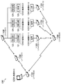
図1は、本発明の例示的実施形態を用いたネットワークシステム100の概略図である。システム100は、無線アドホックネットワークである。このシステム100は、近接する小型無線端末が自律的にネットワークを構築するよう構成される。システム100は、複数のノード装置110,110,…と、ユーザ機器120,120,…とを備えている。各ノード装置110には、ユーザ機器120が接続されている。ユーザ機器としては、PC(パーソナルコンピュータ)120A、電子機器120B、センサ120C等が含まれる(以下、各ユーザ機器を区別しないときには、単に、「ユーザ機器120」と称する)。
-System overview-
FIG. 1 is a schematic diagram of a
複数のユーザ機器においては、PC120Aがマスタ機として機能し、それ以外の電子機器120B,120B,…及びセンサ120C,120C,…がスレーブ機として機能する。つまり、PC120Aが、電子機器120B,120B,…及びセンサ120C,120C,…を一方的に制御する。以下、PC120Aをマスタユーザ機器120Aと、電子機器120Bをスレーブユーザ機器120Bと、センサ120Cをスレーブユーザ機器120Cとも称する。各ユーザ機器120は、固有の機器IDを有している。以下、特定の機器IDの電子機器120B又はセンサ120Cについて言及するときには、符号「120B」,「120C」の後に機器IDを括弧書きで付す。例えば、電子機器120Bの機器IDが「1」の場合は、電子機器120B(1)のように表す。 In a plurality of user devices, the PC 120A functions as a master device, and the other electronic devices 120B, 120B,... And the sensors 120C, 120C,. That is, the PC 120A controls the electronic devices 120B, 120B,... And the sensors 120C, 120C,. Hereinafter, the PC 120A is also referred to as a master user device 120A, the electronic device 120B is also referred to as a slave user device 120B, and the sensor 120C is also referred to as a slave user device 120C. Each user device 120 has a unique device ID. Hereinafter, when referring to the electronic device 120B or the sensor 120C having a specific device ID, the device ID is appended in parentheses after the signs “120B” and “120C”. For example, when the device ID of the electronic device 120B is “1”, it is represented as an electronic device 120B (1).
複数のノード装置110,110,…間は、無線で結合される。すなわち、複数のノード装置110,110,…は、無線ネットワークを構築している。複数のノード装置110,110,…には、1つの基地局ノード装置110Aと、複数の子ノード装置110B,110B,…とが含まれている。基地局ノード装置110Aが親機であり、子ノード装置110Bが子機である。基地局ノード装置110Aには、前記マスタユーザ機器120Aが接続されている。子ノード装置110Bには、前記スレーブユーザ機器120B,120Cが接続されている。以下、各ノード装置を区別しないときには、単に、「ノード装置110」と称する。
The plurality of
各ノード装置110は、固有のノードIDを有している。基地局ノード装置110AのノードIDは、「0」であり、子ノード装置110BのノードIDは、「0」以外の数字である。以下、特定のノードIDのノード装置110について言及するときには、符号「110」,「110A」,「110B」の後にノードIDを括弧書きで付す。
Each
複数のノード装置110,110間の無線リンクは、例えば、2.4GHz帯を用いたIEEE802.15.4に準拠する短距離無線ネットワークであり得る。このIEEE802.15.4は、PAN(Personal Area Network)又はWPAN(Wireless Personal Area Network)と呼ばれる無線通信規格の一つであり、低コスト・低消費電力で、高い信頼性とセキュリティを持つ。また、無線リンクは、上述の特定の無線ネットワークに限定されず、典型的にはパケットの形で情報をやりとりできる任意の適切なネットワークであり得る。
The wireless link between the plurality of
また、ノード装置110は、自動中継機能を有し、通信環境を察知して自律的にネットワークを構成し得る。例示的なネットワークは、真メッシュであり、ホップ数も実質的に無制限である。換言すれば本発明の実施形態は、マルチホップの無線ネットワークを使用可能である。こうして、1つのノード装置110を1つの無線端末として、無線アドホックネットワークが構築される。
Further, the
ノード装置110は、基板上に取り付けられた、半導体素子を含む回路要素群によって典型的には実現され得る。典型的には、ノード装置110は、ユーザ機器からのアナログ信号、及び無線ネットワークのための高周波信号を扱うアナログ回路と、MCUを主要素とするデジタル回路との組み合わせによって実現され得る。
The
ノード装置110の制御は、典型的にはソフトウェアによって実現され得る。すなわち、ノード装置110の制御は、典型的にはコンピュータで読み取り可能な媒体に記憶されたソフトウェアによって実現され得る。コンピュータで読み取り可能な媒体には、ハードディスクドライブ、半導体メモリ等がある。代替として、ノード装置110の制御は、ソフトウェア及びハードウェアの組み合わせ、又はハードウェアのみによって実現され得る。
The control of the
電子機器120Bは、各種の電子機器である。例えば、電子機器120B(1)は、空調機本体121と、該空調機本体121を制御する制御部122とを有する空調機である。電子機器120B(2)は、恒温槽本体123と、該恒温槽本体123を制御する制御部124とを有する恒温槽である。電子機器120B(3)は、照明本体125と、該照明本体125を制御する制御部126とを有する照明装置である。以下、電子機器120B(1)を空調機120B(1)と、電子機器120B(2)を恒温槽120B(2)と、電子機器120B(3)を照明装置120B(3)とも称する。制御部122,124,126に、子ノード装置110B(1)が結合されている。電子機器120Bは、PC120Aからの電文を受け取って、該電文に応じた様々な処理を実行する。例えば、空調機120B(1)では、制御部122がPC120Aからの電文に応じて、空調機本体121をオン/オフしたり、空調機本体121の設定温度を変更したりする。恒温槽120B(2)では、制御部124がPC120Aからの電文に応じて、恒温槽本体123をオン/オフしたり、恒温槽本体123の設定温度を変更したりする。照明装置120B(3)では、制御部126がPC120Aからの電文に応じて、照明本体125をオン/オフしたり、照明本体125の調光を実行したりする。
The electronic device 120B is various electronic devices. For example, the electronic device 120 </ b> B (1) is an air conditioner that includes an
センサ120Cは、各種の物理量(温度、湿度、電流、電圧、電力等)を計測・検出するものであって、任意の適切な計測機器であり得る。例えば、センサ120C(11)は、空調機120B(1)で温度制御される部屋の温度を測定する温度センサである。センサ120C(12)は、恒温槽本体123の温度を測定する温度センサである。センサ120C(13)は、照明装置120B(3)の近傍に設けられた人感センサである。以下、センサ120C(11)を温度センサ120C(11)と、センサ120C(12)を温度センサ120C(12)と、センサ120C(13)を人感センサ120C(13)と称することもある。センサ120Cは、PC120Aからの電文を受け取って、該電文に応じた様々な処理を実行する。例えば、温度センサ120C(1),120C(3)は、PC120Aからの電文に応じて、温度の検出値を返信するように構成されている。人感センサ120C(2)は、PC120Aからの電文に応じて、人を検知しているか否かを返信するように構成されている。 The sensor 120C measures and detects various physical quantities (temperature, humidity, current, voltage, power, etc.), and may be any appropriate measuring device. For example, the sensor 120C (11) is a temperature sensor that measures the temperature of a room whose temperature is controlled by the air conditioner 120B (1). The sensor 120 </ b> C (12) is a temperature sensor that measures the temperature of the thermostatic chamber body 123. The sensor 120C (13) is a human sensor provided in the vicinity of the lighting device 120B (3). Hereinafter, the sensor 120C (11) may be referred to as a temperature sensor 120C (11), the sensor 120C (12) may be referred to as a temperature sensor 120C (12), and the sensor 120C (13) may be referred to as a human sensor 120C (13). The sensor 120C receives a message from the PC 120A and executes various processes according to the message. For example, the temperature sensors 120C (1) and 120C (3) are configured to return a detected temperature value in response to a message from the PC 120A. The human sensor 120C (2) is configured to return whether or not a person is detected in response to a message from the PC 120A.
電子機器120B及びセンサ120Cはそれぞれ、子ノード装置110Bに有線で結合される。子ノード装置110B、電子機器120B及びセンサ120Cは、共通の通信規格(本実施形態では、RS485)のインタフェースを有している。すなわち、電子機器120Bは、RS485ケーブルを介して子ノード装置110Bに接続されている。尚、通信規格は、RS485に限られるものではなく、RS422、RS232C、UART(Universal Asynchronous Receiver Transmitter)等であってもよい。
Each of electronic device 120B and sensor 120C is coupled to
尚、PC120Aは、電子機器120B及びセンサ120Cの通信規格に対応させるべく、基地局ノード装置110Aと、USB−RS485コンバータを介して有線で接続される。尚、基地局ノード装置110Aに接続されるユーザ機器120が、他のユーザ機器120と共通の通信規格を本来的に有する場合には、USB−RS485コンバータのような変換装置をユーザ機器120に設ける必要はない。
The PC 120A is connected to the base
また、PC120A、電子機器120B及びセンサ120Cは、共通のプロトコルを有している。そのため、PC120Aと電子機器120B及びセンサ120Cとは、互いに電文のやりとりを行うことができる。詳しくは、PC120Aは、電子機器120Bに対する種々の電文を出力する。PC120Aからの電文は、ノード装置110,110,…で構築されたネットワークシステムを介して、電子機器120B及びセンサ120Cへ送信される。また、PC120Aは、ノード装置110,110,…で構築されたネットワークシステムを介して、電子機器120B及びセンサ120Cからの応答電文を受信する。
The PC 120A, the electronic device 120B, and the sensor 120C have a common protocol. Therefore, the PC 120A, the electronic device 120B, and the sensor 120C can exchange messages with each other. Specifically, the PC 120A outputs various messages for the electronic device 120B. A telegram from the PC 120A is transmitted to the electronic device 120B and the sensor 120C via a network system constructed by the
ノード装置110は、電文を送信するときには、該電文を含むパケットを生成し、該パケットを変調して送信する。また、ノード装置110は、パケットを受信したときには、該パケットを復調して、該パケットから電文を読み出す。ノード装置110の無線信号の符号化及び変調・復調のための方式には様々なものがある。本実施形態では、上述のIEEE802.15.4に準拠した方式が用いられる。
When transmitting a message, the
PC120Aは、例えば、GUI(グラフィカルユーザインタフェース)を備えるソフトウェアを用いて、センサ120Cから受け取られたデータを視覚的に表示したり、統計的に処理したりできる。また、PC120Aは、例えば、ソフトウェアを用いて、電子機器120Bに様々な制御信号を送信することができる。PC120Aは、センサ120Cから受け取ったデータに基づいて、電子機器120Bへの制御信号を作成し得る。前記ソフトウェアは、例えば通信状態の確認、データの数値表示、グラフ表示、値の分布カラーマッピング、データの記録、データのエクスポート、端末設定の変更等を行うことができる。 The PC 120A can visually display or statistically process data received from the sensor 120C using, for example, software including a GUI (graphical user interface). Further, the PC 120A can transmit various control signals to the electronic device 120B, for example, using software. The PC 120A can create a control signal to the electronic device 120B based on the data received from the sensor 120C. The software can perform, for example, confirmation of a communication state, data numerical display, graph display, value distribution color mapping, data recording, data export, terminal setting change, and the like.
−ノード装置のハードウェア構成−
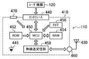
図2は、本発明の例示的実施形態のために用いられるノード装置110のブロック図である。
-Hardware configuration of node equipment-
FIG. 2 is a block diagram of the
ノード装置110は、RFユニット410及びアンテナ430を備える。RFユニット410には、ユーザ機器120からのデータが入力される。RFユニット410は、ユーザ機器120が出力した計測データを無線信号に変換して、アンテナ430から他のノード装置110、例えば上流ノード(基地局ノード装置110A等)へ送信する。
The
RFユニット410は、インタフェース440、DC(直流)電源445、MCU(Micro Controller Unit)450、ROM(読み出し専用メモリ)452、RAM(ランダムアクセスメモリ)454、タイマ456、無線送受信部458、RFインタフェース460、及び切替スイッチ470を有する。インタフェース440は、ユーザ機器120によって出力された信号をMCU450が処理できる適当な信号(例えば10ビットデジタル信号)に変換する。このインタフェース440は、ユーザ機器120の通信規格と共通のインタフェースであり、本実施形態では、RS485インタフェースである。DC電源445は、RFユニット410の各機能ブロックに直流電源を供給する。DC電源445は、例えば直流3Vを供給するリチウム電池であり得る。
The
MCU450は、ノード装置110の機能を実現するのに用いられるマイクロプロセッサである。ROM452又はRAM454は、ノード装置110の機能を実現するのに必要なプログラム及びデータを記憶している。タイマ456は、例えば電源をオフにするタイミングを計測し、所定時間が経過したときに、DC電源445からの電源供給を断つようMCU450をトリガする。MCU450は、ROM452、RAM454、及びタイマ456などの周辺素子をその中に含んでもよい。
The
無線送受信部458は、MCU450からのデータを他のノード装置110へ送る応答パケットに変換したり、他のノード装置110から受け取られた要求パケットをデータに変換したりする。RFインタフェース460は、無線送受信部458から出力されたパケットをRF信号に変換し、アンテナに出力したり、アンテナで受け取られたRF信号からパケットを再生し、無線送受信部458に出力したりする。
The wireless transmission /
切替スイッチ470は、ノード装置110のノードIDを設定するためのダイヤル式のスイッチである。ノードIDを「0」に設定されたノード装置110が基地局ノード装置として機能する。一方、ノードIDが「0」以外に設定されたノード装置110は、子ノード装置として機能する。
The
尚、機能ブロック群の一部又は全ては、適宜、結合されることによって一体化されて実現されてもよい。例えば、RFユニット410は、ハイブリッドIC(集積回路)として実現されてもよい。さらには、RFユニット410及びアンテナ430を一つの基板に一体化して実現されてもよい。
Part or all of the functional block groups may be integrated and realized by being appropriately combined. For example, the
−ネットワーク設定−
ノード装置110は、ネットワーク設定(例えば、通信仕様やプロトコル仕様)を適宜設定することによって、様々な種類のユーザ機器120,120,…に対応可能(即ち、接続可能且つ通信可能)に構成されている。具体的には、ノード装置110は、各種の設定パラメータを有しており、これらの設定パラメータを変更することによって、各種のユーザ機器120と通信が可能となるように構成されている。設定パラメータには、ユーザ機器120の通信仕様に関する通信パラメータと、ユーザ機器120のプロトコル仕様に関するプロトコルパラメータとが含まれる。通信パラメータには、ボーレート(4800bps/9600bps/19200bps/…)、データビット(8ビット/7ビット)、パリティ(なし/奇数/偶数)、ストップビット(1ビット/2ビット)等が含まれる。プロトコルパラメータには、スタートコード(01〜FF)、エンドコード(01〜FF)、エンドコードからパケット終端までのオフセット(0〜9)、先頭から送信先アドレスまでのオフセット(1〜99)、送信先アドレスの長さ(0〜6)、送信先アドレスの表現形式(10進ASCII/16進ASCII/LEバイナリ/BEバイナリ)等が含まれる。
-Network settings-
The
−タイマ機能−
ノード装置110は、タイマ機能を有している。ノード装置110は、タイマ付コマンドを受信すると、以下のタイマ処理を実行する。タイマ付コマンドには、待機時間、タイマ回数及び制御コマンドが含まれている。ノード装置110は、待機時間及びタイマ回数が設定可能となっている。待機時間は、ノード装置110がタイマ付コマンドを受信してから制御コマンドをユーザ機器120へ送信するまでの時間である。タイマ回数は、待機時間経過後に制御コマンドをユーザ機器120へ送信するという処理を繰り返して行う回数である。
−Timer function−
The
以下、タイマ処理について説明する。ノード装置110は、タイマ付コマンドを受信すると、該タイマ付コマンドに基づいて待機時間及びタイマ回数を設定する。それと共に、ノード装置110は、タイマ付コマンドに含まれる制御コマンドをRAM454に記憶させ且つタイマ456を始動させる。ノード装置110は、タイマ456による計時時間が設定した待機時間を超えると、RAM454に記憶しておいた制御コマンドを読み出し、ユーザ機器120へ送信する。このとき、ノード装置110は、タイマ456をリセットする。設定されたタイマ回数が2回以上であるときには、ノード装置110は、タイマ456を再び始動させる。そして、再び待機時間が経過すると、ノード装置110は、制御コマンドを再びユーザ機器120へ送信する。このように、ノード装置110は、待機時間だけ待機しては制御コマンドを送信するという処理をタイマ回数だけ繰り返す。
Hereinafter, the timer process will be described. When receiving the command with timer, the
尚、ノード装置110は、待機中、即ち、待機時間経過する前に新たなタイマ付コマンドを受信すると、タイマ456をリセットすると共に、新たなタイマ付コマンドに基づいてタイマ処理を実行する。
Note that when receiving a new command with timer while waiting, that is, before the standby time has elapsed, the
−ネットワークの構築−
ノード装置110は、上述の如く、自律的にネットワークを構築する。詳しくは、ノード装置110は、電源がオンされると、ルーティングを開始する。ノード装置110は、隣接するノード装置110にビーコンメッセージ(ルーティングパケットとも呼ばれる)を送信する等して、通信状態が良好なノード装置110との間で通信経路を構築する。各ノード装置110は、それ自身と通信経路を構築する上流側と下流側のノード装置110とを記憶している。本実施形態では、PC120A側を上流とし、PC120Aとは反対側を下流としている。さらに、各ノード装置110は、下流側に結合される全てのノード装置110と該ノード装置110のそれぞれへパケットを伝達するために次に中継すべきノード装置110とを記憶している。ノード装置110は、電源をオンにした直後だけでなく、前記ビーコンメッセージを定期的に送信して、通信状態が良好な通信経路を更新している。
-Network construction-
As described above, the
−PCによる制御−
以下、PC120Aによる電子機器120Bの制御について説明する。
-Control by PC-
Hereinafter, control of the electronic device 120B by the PC 120A will be described.
PC120Aは、センサ120Cの検出結果に基づいて電子機器120Bを制御している。例えば、PC120Aは、センサ120Cの検出温度に基づいて、空調機120B(1)が設置された部屋の室温が所定の設定温度となるように、空調機120B(1)をフィードバック制御する。例えば、PC120Aは、室温が上限目標温度を越えると空調機120B(1)をオフ状態とし、室温が下限目標温度を下回ると空調機120B(1)をオン状態とする。 The PC 120A controls the electronic device 120B based on the detection result of the sensor 120C. For example, the PC 120A performs feedback control of the air conditioner 120B (1) based on the temperature detected by the sensor 120C so that the room temperature of the room in which the air conditioner 120B (1) is installed becomes a predetermined set temperature. For example, the PC 120A turns off the air conditioner 120B (1) when the room temperature exceeds the upper limit target temperature, and turns on the air conditioner 120B (1) when the room temperature falls below the lower limit target temperature.
詳しくは、PC120Aは、温度センサ120C(11)へ計測データを要求する要求コマンドを生成し、該要求コマンドを基地局ノード装置110Aへ送信する。基地局ノード装置110Aは、要求コマンドを含む要求パケットを生成し、該要求パケットを送信する。基地局ノード装置110Aから送信された要求パケットは、種々の子ノード装置110B(図1では、子ノード装置110B(20)を経由して、子ノード装置110B(11)に到達する。子ノード装置110B(11)は、パケットのペイロードデータの中から要求コマンドを読み出し、該要求コマンドを温度センサ120C(11)に有線で送信する。温度センサ120C(11)は、要求コマンドに応答して、計測データを電文形式の信号に符号化し、該応答コマンドを子ノード装置110B(11)へ返信する。
Specifically, the PC 120A generates a request command for requesting measurement data to the temperature sensor 120C (11), and transmits the request command to the base
子ノード装置110B(11)は、該応答コマンドを受信すると、応答パケットを生成し、該応答パケットを基地局ノード装置110Aへ送信する。応答パケットは、要求パケットとは逆の流れで、基地局ノード装置110Aまで到達する。
When the
基地局ノード装置110Aは、応答パケットのペイロードデータの中から応答コマンドを読み出し、該応答コマンドをPC120Aに有線で送信する。PC120Aは、応答コマンドを受信すると、該応答コマンドを復号化して、計測データを得る。
The base
PC120Aは、このようなセンサ120Cの計測データの取得を定期的に行って、空調機120B(1)が設置された部屋の室温を監視している。そして、PC120Aは、室温が上限目標温度を超えると、空調機120B(1)をオフ状態に制御する。一方、PC120Aは、室温が下限目標温度を下回ると、空調機120B(1)をオン状態に制御する。尚、空調機120B(1)自体も、室温を検知し、該室温に基づいて出力を制御している。つまり、PC120Aは、空調機120B(1)とは別に室温を監視し、該室温に基づいて空調機120B(1)を強制的に制御する。 The PC 120A periodically acquires the measurement data of the sensor 120C, and monitors the room temperature of the room where the air conditioner 120B (1) is installed. And PC120A will control air conditioner 120B (1) to an OFF state, if room temperature exceeds upper limit target temperature. On the other hand, when the room temperature falls below the lower limit target temperature, PC 120A controls air conditioner 120B (1) to be in the on state. The air conditioner 120B (1) itself also detects the room temperature and controls the output based on the room temperature. That is, the PC 120A monitors the room temperature separately from the air conditioner 120B (1), and forcibly controls the air conditioner 120B (1) based on the room temperature.
詳しくは、PC120Aは、室温が上限目標温度を超える場合には空調機120B(1)をオフ状態に変更するオフコマンドを送信する一方、室温が下限目標温度を下回る場合には空調機120B(1)をオン状態に変更するオンコマンドを基地局ノード装置110Aへ送信する。基地局ノード装置110Aは、PC120Aから送信されたコマンドを含む変更要求パケットを生成し、該変更要求パケットを無線送信する。送信された変更要求パケットは、種々の子ノード装置110B(図1では、子ノード装置110B(7))を経由して、子ノード装置110B(1)に到達する。子ノード装置110B(1)は、受信した変更要求パケットのペイロードデータからコマンドを読み出し、該コマンドを空調機120B(1)へ送信する。空調機120B(1)は、コマンドに応じて状態を変更する。すなわち、制御部122は、オフコマンドを受信したときには、空調機本体121の運転を停止する。また、制御部122は、オンコマンドを受信したときには、空調機本体121の運転を開始する。
Specifically, the PC 120A transmits an off command for changing the air conditioner 120B (1) to an off state when the room temperature exceeds the upper limit target temperature, while the air conditioner 120B (1) when the room temperature falls below the lower limit target temperature. ) Is transmitted to the base
このように、PC120Aは、温度センサ120C(11)からの検出温度に基づいて空調機120B(1)をフィードバック制御している。 Thus, the PC 120A performs feedback control of the air conditioner 120B (1) based on the detected temperature from the temperature sensor 120C (11).
ここで、基地局ノード装置110Aと子ノード装置110Bとの間は無線通信であるため、通信環境が悪化した場合等には電波途絶が生じ得る。電波途絶が生じると、コマンドが電子機器120Bまで届かず、PC120Aは電子機器120Bの状態を制御できなくなる。その場合、電子機器120Bは、電波途絶が生じたときの制御状態がずっと継続することになる。電子機器120Bの制御状態によっては、ずっと継続することが好ましくないものもある。例えば、空調機120B(1)をオン状態とし後にオフ状態に変更する際に電波途絶が生じると、空調機120B(1)はオン状態が継続され、電力を消費し続ける。そのため、オン状態が継続することは、省エネの観点からは好ましくない。
Here, since radio communication is performed between the base
そこで、PC120Aは、オンコマンドを送信するときに、タイマ付オフコマンドも送信する。詳しくは、PC120Aは、室温が下限目標温度を下回ったときに、オンコマンドに加えて、タイマ付オフコマンドを基地局ノード装置110Aへ送信する。タイマ付オフコマンドは、所定の待機時間経過後に空調機120B(1)をオフ状態に変更する制御を所定のタイマ回数だけ実行させるコマンドである。基地局ノード装置110Aは、オンコマンド及びタイマ付オフコマンドを含む変更要求パケットを生成し、該変更要求パケットを無線送信する。子ノード装置110B(1)は、変更要求パケットを受信すると、該変更要求パケットのペイロードデータからオンコマンド及びタイマ付オフコマンドを読み出す。子ノード装置110B(1)は、オンコマンドを空調機120B(1)へ送信する一方、オフコマンドをRAM454に一時的に記憶する。それと共に、子ノード装置110B(1)は、タイマ付オフコマンドに基づいて待機時間及びタイマ回数を設定し、タイマ処理を開始する。すなわち、子ノード装置110B(1)は、タイマ456の計時を開始する。空調機120B(1)は、オンコマンドを受信すると、オン状態となり、空調機本体121の運転を開始する。
Therefore, the PC 120A also transmits an off command with a timer when transmitting the on command. Specifically, when the room temperature falls below the lower limit target temperature, the PC 120A transmits an off command with timer to the base
その後、PC120Aのフィードバック制御により、子ノード装置110B(1)がオフコマンドを含む変更要求パケットを受信したときには、子ノード装置110B(1)は、空調機120B(1)をオフ状態とすると共に、タイマ456の計時をリセットしてタイマ処理を終了する。
Thereafter, when the
一方、子ノード装置110B(1)は、タイマ456の計時時間が前記待機時間を経過するまで、何の変更要求パケットも受信しないときには、RAM454からオフコマンドを読み出し、該オフコマンドを空調機120B(1)へ送信する。空調機120B(1)は、オフコマンドを受信すると、オフ状態となり、空調機本体121の運転を停止する。
On the other hand, when the
つまり、子ノード装置110B(1)は、タイマ付オフコマンドを受信してから何のコマンドも受信することなく待機時間が経過したときには、空調機120B(1)を自動的にオフ状態に変更する。こうすることで、空調機120B(1)をオン状態に変更した後に電波途絶が生じて、子ノード装置110B(1)にオフコマンドが到達しない場合であっても、空調機120B(1)を確実にオフ状態とすることができる。その結果、空調機120B(1)をオフ状態にすることができずに電力を消費し続けてしまうということを防止することができる。
That is, the
尚、PC120Aは、タイマ付オフコマンドで設定した待機時間よりも長い間、空調機120B(1)のオン状態を維持させる場合には、タイマ付オフコマンドを送信してから待機時間が経過する前に、状態を維持させるコマンドを送信する。本実施形態では、PC120Aは、タイマ付オフコマンドを再び送信する。すると、基地局ノード装置110Aは、タイマ付オフコマンドを含む変更要求パケットを生成し、該変更要求パケットを無線送信する。子ノード装置110B(1)は、変更要求パケットを受信すると、該変更要求パケットのペイロードデータからタイマ付オフコマンドを読み出す。そして、子ノード装置110B(1)は、タイマ456をリセットして、読み出したタイマ付オフコマンドに基づいてタイマ処理を新たに開始する。このように、子ノード装置110B(1)は、タイマ処理中に新たなタイマ付オフコマンドを受信すると、タイマ処理を更新する。
If the PC 120A maintains the ON state of the air conditioner 120B (1) for a longer time than the standby time set by the timer-off command, before the standby time elapses after transmitting the timer-off command. Sends a command to maintain the state. In the present embodiment, the PC 120A transmits the off command with timer again. Then, the base
尚、状態を維持させるコマンドは、タイマ付オフコマンドに限られるものではない。状態を維持させるコマンドとして、オンコマンド及びタイマ付オフコマンドを送信してもよいし、オンコマンドだけを送信してもよいし、それ専用のコマンドを送信してもよい。 The command for maintaining the state is not limited to the off command with timer. As a command for maintaining the state, an on command and an off command with a timer may be transmitted, only an on command may be transmitted, or a command dedicated thereto may be transmitted.
このように、空調機120B(1)がオン状態に変更されるときには、所定の待機時間経過後にオフ状態に変更するタイマ処理も開始される。ここで、空調機120B(1)がオン状態に変更されるということは、オンコマンドが子ノード装置110B(1)へ到達したことを意味し、それはすなわち、電波途絶が生じていないことを意味する。そのため、PC120Aは、オンコマンドを空調機120B(1)へ送信するときには、タイマ付オフコマンドも送信する。オンコマンドが子ノード装置110B(1)に到達するのであれば、タイマ付オフコマンドも子ノード装置110B(1)に到達するからである。もし、このときに電波途絶が生じると、タイマ付オフコマンドが子ノード装置110B(1)に到達しないが、オンコマンドも子ノード装置110B(1)に到達しない。そのため、空調機120B(1)がオン状態に変更されることもなく、省エネの観点からも問題はない。また、タイマ処理は、電波途絶が生じた場合のバックアップとしての機能であるため、空調機120B(1)のオン状態を維持させる場合には、PC120Aから継続のためのコマンドを送信することによって、タイマ処理が更新される。その結果、オフコマンドが子ノード装置110B(1)へ送信されることがなく、空調機120B(1)のオン状態が維持される。
Thus, when the air conditioner 120B (1) is changed to the on state, timer processing for changing to the off state after a predetermined waiting time has elapsed is also started. Here, the fact that the air conditioner 120B (1) is changed to the on state means that the on command has reached the
尚、PC120Aは、空調機120B(1)へオフコマンドを送信するときには、タイマ付きコマンドを送信しない。 Note that the PC 120A does not transmit a command with a timer when transmitting an off command to the air conditioner 120B (1).
以上、空調機120B(1)の例においては、オン状態が第1の状態の一例であり、オフ状態が第2の状態の一例であり、オンコマンドが第1電文の一例であり、タイマ付オフコマンドが第2電文の一例である。 As described above, in the example of the air conditioner 120B (1), the on state is an example of the first state, the off state is an example of the second state, the on command is an example of the first message, and a timer is attached. The off command is an example of a second message.
次に、恒温槽120B(2)の制御について説明する。PC120Aは、空調機120B(1)の場合と同様に、温度センサ120C(12)からの検出温度に基づいて恒温槽120B(2)をフィードバック制御している。尚、恒温槽120B(2)自体も、国オン槽本体123の温度を検知し、該温度に基づいて出力を制御している。つまり、PC120Aは、恒温槽120B(2)とは別に温度を監視し、該温度に基づいて恒温槽120B(1)を2制的に制御する。恒温槽120B(2)の場合は、電波途絶のためにオフ状態が継続すると、恒温槽本体123の温度を維持できなくなってしまう。そのため、オフ状態が継続することは、恒温槽本来の目的の観点からは好ましくない。 Next, control of the thermostat 120B (2) will be described. Similarly to the case of the air conditioner 120B (1), the PC 120A performs feedback control of the thermostatic chamber 120B (2) based on the temperature detected from the temperature sensor 120C (12). The thermostat 120B (2) itself also detects the temperature of the country-on-tank body 123 and controls the output based on the temperature. That is, the PC 120A monitors the temperature separately from the thermostatic bath 120B (2), and controls the thermostatic bath 120B (1) in two ways based on the temperature. In the case of the thermostatic chamber 120B (2), if the off state continues due to radio wave interruption, the temperature of the thermostatic chamber body 123 cannot be maintained. Therefore, it is not preferable that the OFF state continues from the viewpoint of the original purpose of the thermostatic bath.
そこで、PC120Aは、オフコマンドを送信するときに、タイマ付オンコマンドも送信する。詳しくは、PC120Aは、室温が上限目標温度を上回ったときに、オフコマンドに加えて、タイマ付オンコマンドを基地局ノード装置110Aへ送信する。タイマ付オンコマンドは、所定の待機時間経過後に恒温槽120B(2)をオン状態に変更する制御を所定のタイマ回数だけ実行させるコマンドである。基地局ノード装置110Aは、オフコマンド及びタイマ付オンコマンドを含む変更要求パケットを生成し、該変更要求パケットを無線送信する。子ノード装置110B(1)は、変更要求パケットを受信すると、該変更要求パケットのペイロードデータからオフコマンド及びタイマ付オンコマンドを読み出す。子ノード装置110B(1)は、オフコマンドを恒温槽120B(2)へ送信する一方、オンコマンドをRAM454に一時的に記憶する。それと共に、子ノード装置110B(1)は、タイマ付オンコマンドに基づいて待機時間及びタイマ回数を設定し、タイマ処理を開始する。すなわち、子ノード装置110B(1)は、タイマ456の計時を開始する。恒温槽120B(2)は、オフコマンドを受信すると、オフ状態となり、恒温槽本体123の運転を停止する。
Therefore, when transmitting the off command, the PC 120A also transmits an on command with a timer. Specifically, when the room temperature exceeds the upper limit target temperature, the PC 120A transmits an on command with timer to the base
その後、PC120Aのフィードバック制御により、子ノード装置110B(1)がオンコマンドを含む変更要求パケットを受信したときには、子ノード装置110B(1)は、恒温槽120B(2)をオン状態とすると共に、タイマ456の計時をリセットしてタイマ処理を終了する。
Thereafter, when the
一方、子ノード装置110B(1)は、タイマ456の計時時間が前記待機時間を経過するまで、何の変更要求パケットも受信しないときには、RAM454からオンコマンドを読み出し、該オンコマンドを恒温槽120B(2)へ送信する。恒温槽120B(2)は、オンコマンドを受信すると、オン状態となり、恒温槽本体123の運転を開始する。
On the other hand, when the
このように、子ノード装置110B(1)は、タイマ付オンコマンドを受信してから何のコマンドも受信することなく待機時間が経過したときには、恒温槽120B(2)を自動的にオン状態に変更する。こうすることで、恒温槽120B(2)をオフ状態に変更した後に電波途絶が生じて、子ノード装置110B(1)にオンコマンドが到達しない場合であっても、恒温槽120B(2)を確実にオン状態とすることができる。その結果、恒温槽120B(2)をオン状態にすることができずに恒温槽本体123を所定の温度に維持できないということを防止することができる。
In this way, the
尚、PC120Aは、タイマ付オンコマンドで設定した待機時間よりも長い間、恒温槽120B(2)のオフ状態を維持させる場合には、タイマ付オンコマンドを送信してから待機時間が経過する前に、状態を維持させるコマンドを送信する。本実施形態では、PC120Aは、タイマ付オンコマンドを再び送信する。すると、基地局ノード装置110Aは、タイマ付オンコマンドを含む変更要求パケットを生成し、該変更要求パケットを無線送信する。子ノード装置110B(1)は、変更要求パケットを受信すると、該変更要求パケットのペイロードデータからタイマ付オンコマンドを読み出す。そして、子ノード装置110B(1)は、タイマ456をリセットして、読み出したタイマ付オンコマンドに基づいてタイマ処理を新たに開始する。このように、子ノード装置110B(1)は、タイマ処理中に新たなタイマ付オンコマンドを受信すると、タイマ処理を更新する。
If the PC 120A maintains the off-state of the thermostatic bath 120B (2) for a longer time than the standby time set by the on-command with timer, before the standby time elapses after transmitting the on-command with timer. Sends a command to maintain the state. In the present embodiment, the PC 120A transmits the on command with timer again. Then, the base
また、PC120Aは、恒温槽120B(2)へオンコマンドを送信するときには、タイマ付きコマンドを送信しない。 Moreover, PC120A does not transmit a command with a timer, when transmitting an ON command to the thermostat 120B (2).
以上、恒温槽120B(2)の例においては、オフ状態が第1の状態の一例であり、オン状態が第2の状態の一例であり、オフコマンドが第1電文の一例であり、タイマ付オンコマンドが第2電文の一例である。 As described above, in the example of the constant temperature bath 120B (2), the off state is an example of the first state, the on state is an example of the second state, the off command is an example of the first message, and a timer is attached. The on command is an example of the second message.
次に、照明装置120B(3)の制御について説明する。PC120Aは、人感センサ120C(13)からの検出結果に基づいて照明装置120B(3)を制御している。詳しくは、PC120Aは、人感センサ120C(13)が人を検知すると、照明装置120B(3)をオン状態に変更する一方、人感センサ120C(13)が人を検知しないようになると、照明装置120B(3)をオフ状態に変更する。そして、照明装置120B(3)の場合は、電波途絶のためにオン状態が継続すると、電力を消費し続け、省エネの観点からは好ましくない。 Next, control of the illumination device 120B (3) will be described. The PC 120A controls the lighting device 120B (3) based on the detection result from the human sensor 120C (13). Specifically, when the human sensor 120C (13) detects a person, the PC 120A changes the lighting device 120B (3) to an on state, while when the human sensor 120C (13) does not detect a person, Change device 120B (3) to the off state. In the case of the lighting device 120B (3), if the ON state continues due to the radio wave interruption, the power is continuously consumed, which is not preferable from the viewpoint of energy saving.
そこで、PC120Aは、オンコマンドを送信するときに、タイマ付オフコマンドも送信する。詳しくは、PC120Aは、人感センサ120C(13)が人を検知すると、オンコマンドに加えて、タイマ付オフコマンドを基地局ノード装置110Aへ送信する。タイマ付オフコマンドは、所定の待機時間経過後に照明装置120B(3)をオフ状態に変更する制御を所定のタイマ回数だけ実行させるコマンドである。基地局ノード装置110Aは、オンコマンド及びタイマ付オフコマンドを含む変更要求パケットを生成し、該変更要求パケットを無線送信する。子ノード装置110B(1)は、変更要求パケットを受信すると、該変更要求パケットのペイロードデータからオンコマンド及びタイマ付オフコマンドを読み出す。子ノード装置110B(1)は、オンコマンドを照明装置120B(3)へ送信する一方、オフコマンドをRAM454に一時的に記憶する。それと共に、子ノード装置110B(1)は、タイマ付オフコマンドに基づいて待機時間及びタイマ回数を設定し、タイマ処理を開始する。すなわち、子ノード装置110B(1)は、タイマ456の計時を開始する。照明装置120B(3)は、オンコマンドを受信すると、オン状態となり、照明本体125の運転を開始する。
Therefore, the PC 120A also transmits an off command with a timer when transmitting the on command. Specifically, when human sensor 120C (13) detects a person, PC 120A transmits an off command with a timer to base
その後、PC120Aの制御により、子ノード装置110B(1)がオフコマンドを含む変更要求パケットを受信したときには、子ノード装置110B(1)は、照明装置120B(3)をオフ状態とすると共に、タイマ456の計時をリセットしてタイマ処理を終了する。
Thereafter, when the
一方、子ノード装置110B(1)は、タイマ456の計時時間が前記待機時間を経過するまで、何の変更要求パケットも受信しないときには、RAM454からオフコマンドを読み出し、該オフコマンドを照明装置120B(3)へ送信する。照明装置120B(3)は、オフコマンドを受信すると、オフ状態となり、照明本体125の運転を停止する。
On the other hand, when the
このように、子ノード装置110B(1)は、タイマ付オフコマンドを受信してから何のコマンドも受信することなく待機時間が経過したときには、照明装置120B(3)を自動的にオフ状態に変更する。こうすることで、照明装置120B(3)をオン状態に変更した後に電波途絶が生じて、子ノード装置110B(1)にオフコマンドが到達しない場合であっても、照明装置120B(3)を確実にオフ状態とすることができる。その結果、照明装置120B(3)をオフ状態にすることができずに照明本体125を所定の温度に維持できないということを防止することができる。
Thus, the
尚、PC120Aは、タイマ付オフコマンドで設定した待機時間よりも長い間、照明装置120B(3)のオン状態を維持させる場合には、タイマ付オフコマンドを送信してから待機時間が経過する前に、状態を維持させるコマンドを送信する。本実施形態では、PC120Aは、タイマ付オフコマンドを再び送信する。すると、基地局ノード装置110Aは、タイマ付オフコマンドを含む変更要求パケットを生成し、該変更要求パケットを無線送信する。子ノード装置110B(1)は、変更要求パケットを受信すると、該変更要求パケットのペイロードデータからタイマ付オフコマンドを読み出す。そして、子ノード装置110B(1)は、タイマ456をリセットして、読み出したタイマ付オフコマンドに基づいてタイマ処理を新たに開始する。このように、子ノード装置110B(1)は、タイマ処理中に新たなタイマ付オフコマンドを受信すると、タイマ処理を更新する。
If the PC 120A maintains the lighting device 120B (3) in the on state for a longer time than the standby time set by the off command with timer, before the standby time elapses after transmitting the off command with timer. Sends a command to maintain the state. In the present embodiment, the PC 120A transmits the off command with timer again. Then, the base
また、PC120Aは、照明装置120B(3)へオフコマンドを送信するときには、タイマ付きコマンドを送信しない。 Further, when the PC 120A transmits an off command to the lighting device 120B (3), the PC 120A does not transmit a command with a timer.
以上、照明装置120B(3)の例においては、オン状態が第1の状態の一例であり、オフ状態が第2の状態の一例であり、オンコマンドが第1電文の一例であり、タイマ付オフコマンドが第2電文の一例である。 As described above, in the example of the lighting device 120B (3), the on state is an example of the first state, the off state is an example of the second state, the on command is an example of the first message, and a timer is attached. The off command is an example of a second message.
尚、子ノード装置110B(1)は、電子機器120Bごとに待機時間及びタイマ回数を設定可能である。例えば、子ノード装置110B(1)は、空調機120B(1)と照明装置120B(3)とで異なる待機時間及びタイマ回数を設定することができる。
The
したがって、本実施形態によれば、ネットワークシステム100は、複数のユーザ機器120,120,…と、該ユーザ機器120,120,…に有線により接続される複数のノード装置110,110,…とを備え、該ノード装置110,110,…の間で無線通信を行う。PC120Aは、空調機120B(1)へ該空調機120B(1)の状態をオン状態に変更するオンコマンドを送信するときに、該オン状態に変更された該空調機120B(1)の状態を所定の待機時間経過後にオフ状態に変更するタイマ付オフコマンドも送信する。前記空調機120B(1)に接続された子ノード装置110B(1)は、前記オンコマンドを受信すると、該オンコマンドを該空調機120B(1)に送信する一方、前記タイマ付オフコマンドを受信すると、前記待機時間経過後にオフコマンドを該空調機120B(1)に送信する。また、PC120Aは、恒温槽120B(2)へ該恒温槽120B(2)の状態をオフ状態に変更するオフコマンドを送信するときに、該オフ状態に変更された該恒温槽120B(2)の状態を所定の待機時間経過後にオン状態に変更するタイマ付オンコマンドも送信する。前記恒温槽120B(2)に接続された子ノード装置110B(1)は、前記オフコマンドを受信すると、該コマンドを該恒温槽120B(2)に送信する一方、前記タイマ付オンコマンドを受信すると、前記待機時間経過後にオンコマンドを該恒温槽120B(2)に送信する。また、PC120Aは、照明装置120B(3)へ該照明装置120B(3)の状態をオン状態に変更するオンコマンドを送信するときに、該オン状態に変更された該照明装置120B(3)の状態を所定の待機時間経過後にオフ状態に変更するタイマ付オフコマンドも送信する。前記照明装置120B(3)に接続された子ノード装置110B(1)は、前記オンコマンドを受信すると、該オンコマンドを該照明装置120B(3)に送信する一方、前記タイマ付オフコマンドを受信すると、前記待機時間経過後にオフコマンドを該照明装置120B(3)に送信する。
Therefore, according to the present embodiment, the
換言すると、本実施形態に係るネットワークシステム100における制御方法は、複数のユーザ機器120,120,…と、該ユーザ機器120,120,…に有線により接続される複数のノード装置110,110,…とを備え、該ノード装置110,110,…の間で無線通信を行うネットワークシステム100において、一の該ユーザ機器120から他の該ユーザ機器120へ電文を送信して該他のユーザ機器120の状態を制御するものである。そして、この制御方法は、PC120Aが、電子機器120Bの状態を変更するための電文を送信する送信工程と、前記電子機器120Bの接続された子ノード装置110Bが、PC120Aからの電文を受信して、該電文を電子機器120Bに送信する受信工程とを含み、前記送信工程においては、前記電子機器120Bの状態を第1の状態に変更する第1電文を送信するときに、該第1の状態に変更された電子機器120Bの状態を所定の待機時間経過後に第2の状態に変更する第2電文も送信し、前記受信工程においては、前記電子機器120Bに接続された子ノード装置110Bは、前記第1電文を受信すると、該第1電文を該電子機器120Bに送信する一方、前記第2電文を受信すると、前記待機時間経過後に該第2電文を該電子機器120Bに送信する。
In other words, the control method in the
こられの構成によれば、電子機器120Bを第1の状態に変更する電文を送信する際に、第1の状態に変更された電子機器120Bを所定待機時間経過後に第2の状態に変更する電文を前もって送信しておく。そのため、電子機器120Bが第1の状態に変更された後に電波途絶が生じたとしても、所定待機時間経過後には電子機器120Bを第2の状態に変更することができる。つまり、電子機器120Bを第1の状態が変更されるということは、前記第1電文が電子機器120Bに到達したことを意味し、つまりは、通信環境は良好であることを意味する。そのため、第1電文を送信するときに、電子機器120Bを将来的に第2の状態にするための第2電文を予め送信しておく。れにより、電子機器120Bを第1の状態に変更した後に電波途絶が生じたとしても、電子機器120Bの状態を第1の状態のままではなく、第2の状態に変更することができる。 According to these configurations, when transmitting a message for changing the electronic device 120B to the first state, the electronic device 120B changed to the first state is changed to the second state after a predetermined waiting time has elapsed. Send a message in advance. Therefore, even if radio wave interruption occurs after the electronic device 120B is changed to the first state, the electronic device 120B can be changed to the second state after the predetermined standby time has elapsed. That is, changing the first state of the electronic device 120B means that the first electronic message has reached the electronic device 120B, that is, the communication environment is good. Therefore, when transmitting the first telegram, a second telegram is sent in advance to put the electronic device 120B in the second state in the future. Thereby, even if radio wave interruption occurs after the electronic device 120B is changed to the first state, the state of the electronic device 120B can be changed to the second state instead of the first state.
ここで、第1及び第2の状態は、電子機器120Bの種類によって異なる。例えば、空調機120B(1)及び照明装置120B(3)であれば、第1の状態はオン状態であり、第2の状態はオフ状態である。恒温槽120B(2)であれば、第1の状態はオフ状態であり、第2の状態はオン状態である。また、第1の状態よりも第2の状態の方が好ましい理由も、電子機器120Bの種類によって異なる。空調機120B(1)及び照明装置120B(3)の場合は、省エネが理由であり、恒温槽120B(2)の場合は、恒温槽120B(2)本来の機能の維持が理由である。つまり、空調機120B(1)及び照明装置120B(3)の場合には、所定の待機時間経過後に自動的にオフ状態とすることによって、エネルギの消費を抑制することができる。また、恒温槽120B(2)の場合には、所定の待機時間経過後に自動的にオン状態とすることによって、恒温槽本来の機能である、恒温槽本体123の温度を一定に保つという機能を発揮させることができる。 Here, the first and second states differ depending on the type of the electronic device 120B. For example, if it is air conditioner 120B (1) and illuminating device 120B (3), a 1st state is an ON state and a 2nd state is an OFF state. If it is thermostat 120B (2), a 1st state is an OFF state and a 2nd state is an ON state. The reason why the second state is preferable to the first state also varies depending on the type of electronic device 120B. In the case of the air conditioner 120B (1) and the lighting device 120B (3), the reason is energy saving, and in the case of the thermostat 120B (2), the reason is that the original function of the thermostat 120B (2) is maintained. That is, in the case of the air conditioner 120B (1) and the lighting device 120B (3), energy consumption can be suppressed by automatically turning off after a predetermined standby time. In the case of the thermostat 120B (2), the function of keeping the temperature of the thermostat body 123, which is the original function of the thermostat, is maintained by automatically turning on after a predetermined waiting time has elapsed. It can be demonstrated.
また、PC120Aは、前記ユーザ機器120Bを前記第1の状態に維持させる場合には、該第1の状態を維持させるための電文を前記待機時間が経過する前に送信する。 In addition, when maintaining the user device 120B in the first state, the PC 120A transmits a message for maintaining the first state before the standby time elapses.
つまり、第2電文が予め送信されているため、ユーザ機器120Bへ何の電文も送信しなければ、待機時間経過後にはユーザ機器120Bは自動的に第2の状態に変更される。そのため、ユーザ機器120Bを第1の状態に維持したい場合には、該第1の状態を維持させるための電文を待機時間が経過する前に送信する。これにより、ユーザ機器120Bが待機時間経過後に自動的に第2の状態に変更されることを阻止し、第1の状態を維持することができる。 That is, since the second message has been transmitted in advance, if no message is transmitted to the user device 120B, the user device 120B is automatically changed to the second state after the standby time has elapsed. Therefore, when it is desired to maintain the user device 120B in the first state, a message for maintaining the first state is transmitted before the standby time elapses. As a result, the user device 120B can be prevented from being automatically changed to the second state after the standby time has elapsed, and the first state can be maintained.
また、本実施形態では、複数のユーザ機器120は、マスタ機として機能するPC120Aと、スレーブ機として機能する電子機器120Bとを含み、PC120Aは、電子機器120Bへ前記第1電文を送信するときに前記第2電文も送信する。つまり、PC120Aが電子機器120Bを一方的に制御し、その際に第1及び第2の電文を送信する。 In the present embodiment, the plurality of user devices 120 includes a PC 120A that functions as a master device and an electronic device 120B that functions as a slave device, and the PC 120A transmits the first electronic message to the electronic device 120B. The second telegram is also transmitted. That is, the PC 120A controls the electronic device 120B unilaterally and transmits the first and second messages at that time.
そして、ノード装置110は、ユーザ機器120に有線により接続されると共に、無線通信可能に構成されており、電文を無線通信を介して受信したときに、待機することなく該電文をユーザ機器120に送信する機能と、所定の待機時間経過後に該電文をユーザ機器120に送信する機能とを有する。ノード装置110をこのように構成することによって、第2の電文を予め送信しておき、ユーザ機器120への第2電文の送信を予約しておくことができる。
The
《その他の実施形態》
本発明は、前記実施形態について、以下のような構成としてもよい。
<< Other Embodiments >>
The present invention may be configured as follows with respect to the embodiment.
前記ネットワークシステム100における、ノード装置110の個数及びユーザ機器120の個数は、前記実施形態に限られるものではない。ノード装置やユーザ機器は、任意の個数とすることができる。また、各ノード装置110には、必ず、ユーザ機器120が接続されている必要はない。
The number of
また、前記実施形態では、基地局ノード装置110Aは1台であるが、これに限られるものではない。例えば、複数の基地局ノード装置110Aを設け、電子機器120Bが接続される子ノード装置110B(1)と一の基地局ノード装置110Aとで無線ネットワークを構成し、センサ120Cが接続される子ノード装置110B(11)〜110B(13)と別の基地局ノード装置とで別の無線ネットワークを構成するようにしてもよい。
Moreover, in the said embodiment, although 110 A of base station node apparatuses are one, it is not restricted to this. For example, a plurality of base
また、前記ノード装置110とユーザ機器120との接続関係は、1対1のものと、1対3のものとが存在するが、これに限られるものではない。すなわち、1つのノード装置110に接続されるユーザ機器120の台数は任意に設定され得る。
The
前記ユーザ機器は、PC120A、電子機器120B及びセンサ120Cを含んでいるが、これに限られるものではない。例えば、ユーザ機器120は、表示機器、電力計、湿度センサ、加速度(衝撃)センサ、光センサ等であってもよい。 The user equipment includes the PC 120A, the electronic equipment 120B, and the sensor 120C, but is not limited thereto. For example, the user device 120 may be a display device, a power meter, a humidity sensor, an acceleration (impact) sensor, an optical sensor, or the like.
また、前記の構成では、PC120Aがマスタ機として機能しているが、これに限られるものではない。マスタ機は、必ずしも、PCである必要はなく、計測機器の何れかであってもよく、PC以外のユーザ機器であってもよい。 In the above configuration, the PC 120A functions as a master machine, but the present invention is not limited to this. The master machine does not necessarily have to be a PC, and may be any one of measuring instruments, and may be a user instrument other than a PC.
さらに、前記ネットワークシステム100においては、マスタスレーブ関係が成立しているが、これに限られるものではない。
Furthermore, in the
前記実施形態では、「第1電文を送信するときに第2電文も送信する」構成の一形態として、第1電文と第2電文とを同じパケットで、即ち、同時に送信しているが、これに限られるものではない。例えば、「第1電文を送信するときに第2電文も送信する」構成のとしては、第1電文を送信する直前に第2電文を送信する構成であってもよいし、第1電文を送信した直後に第2電文を送信する構成であってもよい。第1電文と第2電文とを同時に送信しなくても、第1電文を送信する直前又は直後であれば、電波状況はあまり変化しないと考えられるため、第1電文及び第2電文の両方を子ノード装置110Bへ到達させることができる。ただし、まず、第1電文の直前に第2電文を送信する構成の方が、第1電文を送信する直後に第2電文を送信する構成よりも好ましい。つまり、第2電文を送信して、その応答を確認した後に第2電文を送信することによって、第1電文を送信するときには前もって第2電文を到達させておくことができる。より好ましくは、第1電文及び第2電文を同時に送信する。これにより、第1電文が子ノード装置110Bへ到達するときには必ず第2電文も到達し、第1電文が子ノード装置110Bへ到達しないときには必ず第2電文も到達しない。
In the embodiment, as one form of the configuration of “send the second message when transmitting the first message”, the first message and the second message are transmitted in the same packet, that is, simultaneously, It is not limited to. For example, the configuration of “sending the second telegram when transmitting the first telegram” may be a configuration of transmitting the second telegram immediately before transmitting the first telegram, or transmitting the first telegram. The configuration may be such that the second telegram is transmitted immediately after. Even if the first telegram and the second telegram are not transmitted at the same time, it is considered that the radio wave condition does not change much immediately before or after the transmission of the first telegram, so both the first telegram and the second telegram are transmitted. It is possible to reach the
また、第1及び第2の状態は、前記実施形態に限られるものではない。ユーザ機器120の種類、使用状況等に応じて第1及び第2の状態は異なる。第2の状態は、フェールセーフの状態、即ち、第1の状態よりも安全側の状態であることが好ましい。例えば、空調機である空調機120B(1)は、省エネの観点から、第1の状態をオン状態とし、第2の状態をオフ状態としているが、これに限られるものではない。空調機120B(1)がサーバルーム等に使用される場合には、空調機120B(1)の本来の機能を重要視して、第1の状態をオフ状態とし、第2の状態をオン状態とすることが好ましい。つまり、電波途絶が生じても必ずオン状態に変更できるようにすることが好ましい。 Further, the first and second states are not limited to the above embodiment. The first and second states differ depending on the type of user device 120, the usage status, and the like. The second state is preferably a fail-safe state, that is, a safer state than the first state. For example, the air conditioner 120B (1) that is an air conditioner has the first state turned on and the second state turned off from the viewpoint of energy saving, but is not limited thereto. When the air conditioner 120B (1) is used in a server room or the like, the first function is turned off and the second state is turned on with an emphasis on the original function of the air conditioner 120B (1). It is preferable that In other words, it is preferable to always be able to change to the ON state even when radio wave interruption occurs.
本発明は、実施形態に限定されず、その精神又は主要な特徴から逸脱することなく他の色々な形で実施することができる。 The present invention is not limited to the embodiments, and can be implemented in various other forms without departing from the spirit or main features thereof.
このように、上述の実施形態はあらゆる点で単なる例示に過ぎず、限定的に解釈してはならない。本発明の範囲は特許請求の範囲によって示すものであって、明細書には何ら拘束されない。さらに、特許請求の範囲の均等範囲に属する変形や変更は、全て本発明の範囲内のものである。 As described above, the above-described embodiment is merely an example in all respects and should not be interpreted in a limited manner. The scope of the present invention is defined by the claims, and is not limited by the specification. Further, all modifications and changes belonging to the equivalent scope of the claims are within the scope of the present invention.
以上説明したように、本発明は、複数のノード装置を備えたネットワークシステム、該ネットワークシステムに用いられるノード装置、及び該ネットワークシステムにおける制御方法について有用である。 As described above, the present invention is useful for a network system including a plurality of node devices, a node device used in the network system, and a control method in the network system.
100 ネットワークシステム
110 ノード装置
110A 基地局ノード装置
110B 子ノード装置
120 ユーザ機器
120A PC(マスタユーザ機器)
120B 電子機器(スレーブユーザ機器)
100
120B Electronic equipment (slave user equipment)
Claims (11)
一の前記ユーザ機器は、他の前記ユーザ機器へ該他のユーザ機器の状態を第1の状態に変更する第1電文を送信するときに、該第1の状態に変更された該他のユーザ機器の状態を所定の待機時間経過後に第2の状態に変更する第2電文も送信し、
前記他のユーザ機器に接続された前記ノード装置は、前記第1電文を受信すると、該第1電文を該他のユーザ機器に送信する一方、前記第2電文を受信すると、前記待機時間経過後に該第2電文を該他のユーザ機器に送信するネットワークシステム。 A network system comprising a plurality of user devices and a plurality of node devices connected to the user devices by wire, and performing wireless communication between the node devices,
When the one user equipment transmits a first telegram for changing the state of the other user equipment to the first state to the other user equipment, the other user changed to the first state A second telegram that changes the state of the device to the second state after a predetermined standby time has passed is also transmitted.
When the node device connected to the other user device receives the first telegram, the node device transmits the first telegram to the other user device, while receiving the second telegram, after the waiting time has elapsed. A network system for transmitting the second telegram to the other user equipment.
前記一のユーザ機器は、前記他のユーザ機器を前記第1の状態に維持させる場合には、該第1の状態を維持させるための電文を前記待機時間が経過する前に送信するネットワークシステム。 The network system according to claim 1,
When the one user device maintains the other user device in the first state, the network device transmits a message for maintaining the first state before the waiting time elapses.
前記第2の状態は、前記第1の状態よりも消費電力が少ない状態又はオフ状態であるネットワークシステム。 The network system according to claim 1 or 2,
The network system in which the second state is a state in which power consumption is less than that in the first state or an off state.
前記複数のユーザ機器は、マスタ機として機能するマスタユーザ機器と、スレーブ機として機能するスレーブユーザ機器とを含み、
前記マスタユーザ機器は、前記スレーブユーザ機器へ前記第1電文を送信するときに前記第2電文も送信するネットワークシステム。 The network system according to any one of claims 1 to 3,
The plurality of user devices include a master user device that functions as a master device, and a slave user device that functions as a slave device,
The network system in which the master user device also transmits the second telegram when transmitting the first telegram to the slave user device.
電文を無線通信を介して受信したときに、待機することなく該電文を前記ユーザ機器に送信する機能と、所定の待機時間経過後に該電文を前記ユーザ機器に送信する機能とを有するノード装置。 A node device capable of wireless communication connected to a user device by wire,
A node device having a function of transmitting a message to the user device without waiting when the message is received via wireless communication, and a function of transmitting the message to the user device after a predetermined waiting time has elapsed.
前記待機時間及び/又は該待機時間経過後に前記電文を送信するという処理を実行する回数を変更可能に構成されているノード装置。 The node device according to claim 5, wherein
A node device configured to be able to change the waiting time and / or the number of times to execute the process of transmitting the message after the waiting time has elapsed.
前記待機時間、待機しているときに、待機を継続する電文を受信したときには、該待機時間の計時をリセットして再開するノード装置。 In the node apparatus according to claim 5 or 6,
A node device that resets and restarts counting of the waiting time when a message for continuing waiting is received while waiting for the waiting time.
前記一のユーザ機器が、前記他のユーザ機器の状態を変更するための電文を送信する送信工程と、
前記他のユーザ機器の接続された前記ノード装置が、前記一のユーザ機器からの電文を受信して、該電文を該他のユーザ機器に送信する受信工程とを含み、
前記送信工程においては、前記他のユーザ機器の状態を第1の状態に変更する第1電文を送信するときに、該第1の状態に変更された該他のユーザ機器の状態を所定の待機時間経過後に第2の状態に変更する第2電文も送信し、
前記受信工程においては、前記他のユーザ機器に接続された前記ノード装置は、前記第1電文を受信すると、該第1電文を該他のユーザ機器に送信する一方、前記第2電文を受信すると、前記待機時間経過後に該第2電文を該他のユーザ機器に送信する制御方法。 In a network system including a plurality of user devices and a plurality of node devices connected to the user devices by wire, and performing wireless communication between the node devices, a message is transmitted from one user device to another user device. A control method for transmitting and controlling the state of the other user equipment,
A transmitting step in which the one user device transmits a message for changing a state of the other user device;
The node device connected to the other user equipment receives a message from the one user equipment and transmits the message to the other user equipment;
In the transmission step, when transmitting a first telegram for changing the state of the other user equipment to the first state, the state of the other user equipment changed to the first state is set to a predetermined standby state. Send a second telegram to change to the second state after the time has passed,
In the receiving step, when the node device connected to the other user device receives the first telegram, the node device transmits the first telegram to the other user device while receiving the second telegram. The control method of transmitting the second telegram to the other user equipment after the standby time has elapsed.
前記送信工程では、前記他のユーザ機器を前記第1の状態に維持する場合には、前記一のユーザ機器が該第1の状態を維持させるための電文を前記待機時間が経過する前に送信する制御方法。 The control method according to claim 8, wherein
In the transmission step, when the other user device is maintained in the first state, the one user device transmits a message for maintaining the first state before the waiting time elapses. Control method to do.
前記第2の状態は、前記第1の状態よりも消費電力が少ない状態又はオフ状態である制御方法。 The control method according to claim 8 or 9,
The control method in which the second state is a state in which power consumption is less than that in the first state or an off state.
前記複数のユーザ機器は、マスタ機として機能するマスタユーザ機器と、スレーブ機として機能するスレーブユーザ機器とを含み、
前記送信工程では、前記マスタユーザ機器が、前記スレーブユーザ機器へ前記第1電文を送信するときに前記第2電文も送信する制御方法。 The control method according to any one of claims 8 to 10,
The plurality of user devices include a master user device that functions as a master device, and a slave user device that functions as a slave device,
In the transmission step, the master user device transmits the second telegram when transmitting the first telegram to the slave user device.
Priority Applications (1)
| Application Number | Priority Date | Filing Date | Title |
|---|---|---|---|
| JP2012068935A JP5941719B2 (en) | 2012-03-26 | 2012-03-26 | Network system and control method |
Applications Claiming Priority (1)
| Application Number | Priority Date | Filing Date | Title |
|---|---|---|---|
| JP2012068935A JP5941719B2 (en) | 2012-03-26 | 2012-03-26 | Network system and control method |
Publications (2)
| Publication Number | Publication Date |
|---|---|
| JP2013201617A true JP2013201617A (en) | 2013-10-03 |
| JP5941719B2 JP5941719B2 (en) | 2016-06-29 |
Family
ID=49521494
Family Applications (1)
| Application Number | Title | Priority Date | Filing Date |
|---|---|---|---|
| JP2012068935A Expired - Fee Related JP5941719B2 (en) | 2012-03-26 | 2012-03-26 | Network system and control method |
Country Status (1)
| Country | Link |
|---|---|
| JP (1) | JP5941719B2 (en) |
Cited By (1)
| Publication number | Priority date | Publication date | Assignee | Title |
|---|---|---|---|---|
| JP2016072977A (en) * | 2014-09-22 | 2016-05-09 | 台達電子工業股▲ふん▼有限公司Delta Electronics,Inc. | Radio communication network system for managing multiple regions and management method thereof |
Citations (5)
| Publication number | Priority date | Publication date | Assignee | Title |
|---|---|---|---|---|
| JP2005322475A (en) * | 2004-05-07 | 2005-11-17 | Koizumi Sangyo Corp | Remote control transmitter of luminaire |
| WO2006006576A1 (en) * | 2004-07-13 | 2006-01-19 | Mitsubishi Denki Kabushiki Kaisha | Information processing device and information processing method |
| JP2006050524A (en) * | 2004-07-08 | 2006-02-16 | Mitsubishi Electric Corp | Network equipment |
| JP2010028377A (en) * | 2008-07-17 | 2010-02-04 | Universal Entertainment Corp | Remote control system |
| JP2012039182A (en) * | 2010-08-03 | 2012-02-23 | Sumitomo Precision Prod Co Ltd | Network system and node device |
-
2012
- 2012-03-26 JP JP2012068935A patent/JP5941719B2/en not_active Expired - Fee Related
Patent Citations (6)
| Publication number | Priority date | Publication date | Assignee | Title |
|---|---|---|---|---|
| JP2005322475A (en) * | 2004-05-07 | 2005-11-17 | Koizumi Sangyo Corp | Remote control transmitter of luminaire |
| JP2006050524A (en) * | 2004-07-08 | 2006-02-16 | Mitsubishi Electric Corp | Network equipment |
| WO2006006576A1 (en) * | 2004-07-13 | 2006-01-19 | Mitsubishi Denki Kabushiki Kaisha | Information processing device and information processing method |
| JP2006054834A (en) * | 2004-07-13 | 2006-02-23 | Mitsubishi Electric Corp | Information processing apparatus and information processing method |
| JP2010028377A (en) * | 2008-07-17 | 2010-02-04 | Universal Entertainment Corp | Remote control system |
| JP2012039182A (en) * | 2010-08-03 | 2012-02-23 | Sumitomo Precision Prod Co Ltd | Network system and node device |
Cited By (1)
| Publication number | Priority date | Publication date | Assignee | Title |
|---|---|---|---|---|
| JP2016072977A (en) * | 2014-09-22 | 2016-05-09 | 台達電子工業股▲ふん▼有限公司Delta Electronics,Inc. | Radio communication network system for managing multiple regions and management method thereof |
Also Published As
| Publication number | Publication date |
|---|---|
| JP5941719B2 (en) | 2016-06-29 |
Similar Documents
| Publication | Publication Date | Title |
|---|---|---|
| CN108028786B (en) | A centralized control system that controls the interaction and collaboration between devices in a mesh network | |
| CN101529403B (en) | Power management system for field devices on a wireless network | |
| US20140300293A1 (en) | Led lighting device and an ledlighting network system | |
| JP2010532635A (en) | Cordless commercial power mesh network router node | |
| JP5507856B2 (en) | Wireless communication system | |
| CN107148038A (en) | Methods, devices and systems for management and communication of wireless mesh networks | |
| JP5685718B2 (en) | Lighting control system | |
| US20140293855A1 (en) | Wireless communication system and wireless router | |
| CN108029155B (en) | mesh network node | |
| JP2011091954A (en) | Power supply device, power receiving device, power supply system, and power supply method | |
| JP2014524180A (en) | Wireless sensor network | |
| JP5687859B2 (en) | Network system and node device | |
| WO2010144465A1 (en) | Wireless power distribution system and device | |
| JP2024123222A (en) | Method and system involving establishing a communications network - Patents.com | |
| US20200044888A1 (en) | Smart home system | |
| JP5941719B2 (en) | Network system and control method | |
| JP5969778B2 (en) | NETWORK SYSTEM, NODE DEVICE, AND CORRECTING CONNECTION RELATION METHOD | |
| JP5290834B2 (en) | Host device | |
| JP6017860B2 (en) | Node device and network system | |
| JP6637355B2 (en) | Network system | |
| JP5805481B2 (en) | Network system and method of identifying corresponding connection relation | |
| JP2013074356A (en) | Network system and node device | |
| CN106504511B (en) | Air conditioner, remote control, air conditioning system and air conditioning remote control method | |
| JP5227867B2 (en) | Host device | |
| CN105703989B (en) | A IoT system for frequency division and time division management |
Legal Events
| Date | Code | Title | Description |
|---|---|---|---|
| A621 | Written request for application examination |
Free format text: JAPANESE INTERMEDIATE CODE: A621 Effective date: 20150218 |
|
| A977 | Report on retrieval |
Free format text: JAPANESE INTERMEDIATE CODE: A971007 Effective date: 20151002 |
|
| A131 | Notification of reasons for refusal |
Free format text: JAPANESE INTERMEDIATE CODE: A131 Effective date: 20151013 |
|
| A521 | Written amendment |
Free format text: JAPANESE INTERMEDIATE CODE: A523 Effective date: 20151211 |
|
| TRDD | Decision of grant or rejection written | ||
| A01 | Written decision to grant a patent or to grant a registration (utility model) |
Free format text: JAPANESE INTERMEDIATE CODE: A01 Effective date: 20160517 |
|
| A61 | First payment of annual fees (during grant procedure) |
Free format text: JAPANESE INTERMEDIATE CODE: A61 Effective date: 20160523 |
|
| R150 | Certificate of patent or registration of utility model |
Ref document number: 5941719 Country of ref document: JP Free format text: JAPANESE INTERMEDIATE CODE: R150 |
|
| LAPS | Cancellation because of no payment of annual fees |