JP2013201636A - Electronic apparatus - Google Patents
Electronic apparatus Download PDFInfo
- Publication number
- JP2013201636A JP2013201636A JP2012069218A JP2012069218A JP2013201636A JP 2013201636 A JP2013201636 A JP 2013201636A JP 2012069218 A JP2012069218 A JP 2012069218A JP 2012069218 A JP2012069218 A JP 2012069218A JP 2013201636 A JP2013201636 A JP 2013201636A
- Authority
- JP
- Japan
- Prior art keywords
- keyboard
- keys
- function
- image
- electronic device
- Prior art date
- Legal status (The legal status is an assumption and is not a legal conclusion. Google has not performed a legal analysis and makes no representation as to the accuracy of the status listed.)
- Pending
Links
- 238000012545 processing Methods 0.000 claims abstract description 25
- 238000000034 method Methods 0.000 claims abstract description 9
- 238000012905 input function Methods 0.000 claims description 22
- 230000003287 optical effect Effects 0.000 description 29
- 230000005540 biological transmission Effects 0.000 description 10
- 238000010586 diagram Methods 0.000 description 5
- 210000003128 head Anatomy 0.000 description 5
- 230000000007 visual effect Effects 0.000 description 5
- 239000004973 liquid crystal related substance Substances 0.000 description 3
- 230000005236 sound signal Effects 0.000 description 3
- 238000002834 transmittance Methods 0.000 description 3
- 238000012937 correction Methods 0.000 description 2
- 238000001514 detection method Methods 0.000 description 2
- 230000000694 effects Effects 0.000 description 2
- 238000005401 electroluminescence Methods 0.000 description 2
- 238000003384 imaging method Methods 0.000 description 2
- 239000000463 material Substances 0.000 description 2
- 239000011159 matrix material Substances 0.000 description 2
- 238000003825 pressing Methods 0.000 description 2
- 238000006243 chemical reaction Methods 0.000 description 1
- 238000004590 computer program Methods 0.000 description 1
- 239000000470 constituent Substances 0.000 description 1
- 230000007423 decrease Effects 0.000 description 1
- 210000005069 ears Anatomy 0.000 description 1
- 239000011521 glass Substances 0.000 description 1
- 238000005286 illumination Methods 0.000 description 1
- 230000013011 mating Effects 0.000 description 1
- 239000002184 metal Substances 0.000 description 1
- 238000012986 modification Methods 0.000 description 1
- 230000004048 modification Effects 0.000 description 1
- 239000013307 optical fiber Substances 0.000 description 1
- 238000001028 reflection method Methods 0.000 description 1
- 239000011347 resin Substances 0.000 description 1
- 229920005989 resin Polymers 0.000 description 1
- 210000001525 retina Anatomy 0.000 description 1
- 230000003746 surface roughness Effects 0.000 description 1
Images


Landscapes
- Input From Keyboards Or The Like (AREA)
Abstract
【課題】文字入力の機能とは異なる機能を割り当てたキーボード上の一部のキーの操作性を向上することが可能な電子機器を提供すること。
【解決手段】文字入力用の複数のキーが配置されたキーボードを備えた電子機器であって、前記キーボードにおいてキー入力されたキーに割り当てられた機能に応じた処理を実行する操作制御部を含み、前記操作制御部は、所与の割当変更条件が満たされた場合に、前記キーボード上の一部のキーに割り当てる機能を、文字入力の機能とは異なる機能に変更する処理を行い、前記キーボード上の一部のキーは、キーの高さ又はキートップの形状が他のキーとは異なるように形成されている。
【選択図】図2To provide an electronic device capable of improving the operability of some keys on a keyboard to which a function different from the function of character input is assigned.
An electronic device including a keyboard on which a plurality of keys for character input are arranged, and includes an operation control unit that executes processing according to a function assigned to the key input on the keyboard. The operation control unit performs a process of changing a function assigned to a part of keys on the keyboard to a function different from a function of character input when a given assignment change condition is satisfied, and the keyboard Some of the upper keys are formed such that the height of the key or the shape of the key top is different from the other keys.
[Selection] Figure 2
Description
本発明は、文字入力用の複数のキーが配置されたキーボードを備えた電子機器に関する。 The present invention relates to an electronic apparatus including a keyboard on which a plurality of keys for character input are arranged.
電子機器には、入力機器として、文字入力用のキーボードに加えて、十字キー(方向キー)や機能ボタン等といった特殊な機能を有する特殊キーを必要とするものがある。このような電子機器用の入力機器として、十字キーが設けられたハウジングと、キーボードが設けられたハウジングと、機能ボタンが設けられたハウジングとを備え、それらが互いに脱着可能に構成されたコントローラーが知られている(特許文献1参照)。 Some electronic devices require special keys having special functions such as a cross key (direction key) and a function button in addition to a character input keyboard as an input device. As an input device for such an electronic device, a controller including a housing provided with a cross key, a housing provided with a keyboard, and a housing provided with function buttons is configured to be detachable from each other. It is known (see Patent Document 1).
上記コントローラーは、3つのハウジングに分かれているため携帯性が悪く携帯可能な電子機器には適さない。また、キーボードの大型化を防ぎつつ特殊キーを使用可能とするために、キーボード上の一部のキーに特殊キーとしての機能を割り当てるといった手法が考えられる。しかしながら、一般にキーボードは類似する形状のキーが隣接して配置される構成であるため、単に機能の割り当てを変更するだけでは、キーボード上のキーを直視せずに特殊キーとしての機能を割り当てられたキーを操作することは困難である。 Since the controller is divided into three housings, it has poor portability and is not suitable for portable electronic devices. Further, in order to make it possible to use special keys while preventing an increase in the size of the keyboard, a method of assigning functions as special keys to some keys on the keyboard can be considered. However, in general, a keyboard has a configuration in which keys having similar shapes are arranged adjacent to each other. Therefore, by simply changing the function assignment, a function as a special key can be assigned without directly looking at the key on the keyboard. It is difficult to operate the keys.
本発明はこのような問題点に鑑みてなされたものである。本発明のいくつかの態様によれば、文字入力の機能とは異なる機能を割り当てたキーボード上の一部のキーの操作性を向上することが可能な電子機器を提供することができる。 The present invention has been made in view of such problems. According to some aspects of the present invention, it is possible to provide an electronic device capable of improving the operability of some keys on a keyboard to which a function different from the function of character input is assigned.
(1)本発明は、文字入力用の複数のキーが配置されたキーボードを備えた電子機器であって、前記キーボードにおいてキー入力されたキーに割り当てられた機能に応じた処理を実行する操作制御部を含み、前記操作制御部は、所与の割当変更条件が満たされた場合に、前記キーボード上の一部のキーに割り当てる機能を、文字入力の機能とは異なる機能に変更する処理を行い、前記キーボード上の一部のキーは、他のキーと識別可能に形成されている。 (1) The present invention is an electronic device including a keyboard on which a plurality of keys for character input are arranged, and an operation control for executing processing according to a function assigned to the key input on the keyboard. The operation control unit performs a process of changing a function assigned to some keys on the keyboard to a function different from a character input function when a given assignment change condition is satisfied. Some keys on the keyboard are formed to be distinguishable from other keys.
本発明によれば、所与の割当変更条件が満たされた場合に、前記キーボード上の一部のキーに割り当てる機能を、文字入力の機能とは異なる機能に変更する処理を行い、当該キーボード上の一部のキーを他のキーと識別可能に形成することで、当該キーボード上の一部のキーの操作性を向上することが可能な電子機器を提供することができる。 According to the present invention, when a given assignment change condition is satisfied, the function assigned to a part of the keys on the keyboard is changed to a function different from the function of character input. By forming a part of the keys so as to be distinguishable from the other keys, an electronic device capable of improving the operability of the part of the keys on the keyboard can be provided.
(2)この電子機器は、前記操作制御部は、所与の割当変更条件が満たされた場合に、前記キーボード上の一部のキーに割り当てる機能を、方向キーとしての機能に変更する処理を行ってもよい。 (2) In the electronic device, the operation control unit performs a process of changing a function assigned to some keys on the keyboard to a function as a direction key when a given assignment change condition is satisfied. You may go.
本発明によれば、所与の割当変更条件が満たされた場合に、前記キーボード上の一部のキーに割り当てる機能を、方向キーとしての機能に変更する処理を行い、当該キーボード上の一部のキーを他のキーと識別可能に形成することで、当該キーボード上の一部のキーの操作性を向上することが可能な電子機器を提供することができる。 According to the present invention, when a given assignment change condition is satisfied, the function assigned to a part of the keys on the keyboard is changed to a function as a direction key, and the part on the keyboard is changed. By forming these keys so as to be distinguishable from other keys, it is possible to provide an electronic device capable of improving the operability of some keys on the keyboard.
(3)この電子機器は、使用者の頭部に装着された状態において使用者に虚像を視認させる画像表示部を備えた頭部装着型表示装置であり、前記キーボードは、前記画像表示部を制御するコントローラーに設けられていてもよい。 (3) This electronic device is a head-mounted display device that includes an image display unit that allows a user to visually recognize a virtual image in a state of being mounted on the user's head, and the keyboard includes the image display unit. It may be provided in the controller to be controlled.
本発明によれば、文字入力の機能とは異なる機能(例えば、方向キーとしての機能)を割り当てられるキーボード上の一部のキーの操作性を向上することが可能な頭部装着型表示装置を提供することができる。 According to the present invention, there is provided a head-mounted display device capable of improving the operability of some keys on a keyboard to which a function different from a character input function (for example, a function as a direction key) is assigned. Can be provided.
(4)この電子機器は、前記画像表示部は、使用者が前記虚像と外界像とを同時に視認可能に構成され、前記キーボード上の一部のキーに割り当てる機能が変更された場合に、前記画像表示部における前記外界像の視認性を変化させる制御を行う表示制御部を更に含んでもよい。 (4) In the electronic device, the image display unit is configured so that a user can view the virtual image and the external image at the same time, and the function assigned to some keys on the keyboard is changed. You may further include the display control part which performs control which changes the visibility of the said external image in an image display part.
本発明によれば、例えば、キーボードを直視しなければキー入力を行うことが困難な場合(キーボード上の全てのキーに文字入力の機能を割り当てた場合)には、外界像であるキーボードの視認性を向上させ、キーボード16を直視しなくても文字入力の機能とは異なる機能を割り当てた一部のキーの操作を容易に行うことができる場合には、外界像の視認性を低下させて虚像の視認性を向上させることができ、利便性を向上することができる。
According to the present invention, for example, when it is difficult to perform key input without directly looking at the keyboard (when a character input function is assigned to all keys on the keyboard), the keyboard that is an external image is visually recognized. If it is possible to easily operate some keys assigned functions different from the character input function without looking directly at the
(5)この電子機器は、前記表示制御部は、前記キーボード上の一部のキーに文字入力の機能が割り当てられた場合には、前記外界像の視認性を向上させる制御を行い、前記キーボード上の一部のキーに文字入力の機能とは異なる機能が割り当てられた場合には、前記外界像の視認性を低下させる制御を行ってもよい。 (5) In the electronic device, when the display control unit is assigned a character input function to some keys on the keyboard, the display control unit performs control to improve visibility of the external image, and the keyboard When a function different from the character input function is assigned to some of the upper keys, control for reducing the visibility of the external image may be performed.
本発明によれば、キーボードを直視しなければキー入力を行うことが困難な場合(キーボード上の全てのキーに文字入力の機能を割り当てた場合)には、外界像であるキーボードの視認性を向上させ、キーボード16を直視しなくても文字入力の機能とは異なる機能を割り当てた一部のキーの操作を容易に行うことができる場合には、外界像の視認性を低下させて虚像の視認性を向上させることができ、利便性を向上することができる。
According to the present invention, when it is difficult to perform key input without looking directly at the keyboard (when a character input function is assigned to all keys on the keyboard), the visibility of the keyboard that is an external image is improved. If it is possible to easily operate some keys assigned functions different from the character input function without looking directly at the
(6)この電子機器は、前記表示制御部は、前記外界像として視認される前記キーボードと前記虚像との位置関係に応じて前記外界像の視認性を変化させる制御を行ってもよい。 (6) In this electronic device, the display control unit may perform control to change the visibility of the external image according to the positional relationship between the keyboard and the virtual image that are visually recognized as the external image.
(7)この電子機器は、前記表示制御部は、前記キーボード上の一部のキーに文字入力の機能が割り当てられ、且つ、前記外界像として視認される前記キーボードと前記虚像とが重複する位置関係である場合に、前記外界像の視認性を向上させる制御を行ってもよい。 (7) In this electronic apparatus, the display control unit is assigned a character input function to some keys on the keyboard, and the keyboard and the virtual image that are visually recognized as the external image overlap. When it is a relationship, you may perform control which improves the visibility of the said external field image.
本発明によれば、キーボードを直視しなければキー入力を行うことが困難な場合(キーボード上の全てのキーに文字入力の機能を割り当てた場合)であり、且つ、外界像であるキーボードと虚像が重複する場合に、外界像であるキーボードの視認性を向上させることができ、利便性を向上することができる。 According to the present invention, it is difficult to perform key input without directly looking at the keyboard (when a character input function is assigned to all keys on the keyboard), and the keyboard and virtual image that are external images. Can overlap the visibility of the keyboard, which is an external image, and the convenience can be improved.
(8)この電子機器は、前記キーボード上の一部のキーは、キーの高さ又はキートップの形状が他のキーとは異なるように形成されていてもよい。 (8) In this electronic apparatus, some keys on the keyboard may be formed such that the key height or the shape of the key top is different from other keys.
本発明によれば、文字入力の機能とは異なる機能を割り当てられるキーボード上の一部のキーの操作性を向上することができる。 According to the present invention, it is possible to improve the operability of some keys on a keyboard to which a function different from the character input function is assigned.
以下、本発明の好適な実施形態について図面を用いて詳細に説明する。なお、以下に説明する実施形態は、特許請求の範囲に記載された本発明の内容を不当に限定するものではない。また以下で説明される構成の全てが、本発明の必須構成要件であるとは限らない。 DESCRIPTION OF EMBODIMENTS Hereinafter, preferred embodiments of the present invention will be described in detail with reference to the drawings. The embodiments described below do not unduly limit the contents of the present invention described in the claims. Also, not all of the configurations described below are essential constituent requirements of the present invention.
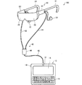
図1は、本実施形態に係る頭部装着型表示装置(電子機器の一例)の構成の一例を示す外観図である。 FIG. 1 is an external view showing an example of the configuration of a head-mounted display device (an example of an electronic apparatus) according to the present embodiment.
頭部装着型表示装置100は、頭部に装着する表示装置であり、ヘッドマウントディスプレイ(Head Mounted Display、HMD)とも呼ばれる。本実施形態の頭部装着型表示装置100は、虚像を視認すると同時に外景(外界像)も直接視認可能な光学透過型(いわゆる、シースルー型)の頭部装着型表示装置である。
The head-mounted
頭部装着型表示装置100は、使用者の頭部に装着された状態において使用者に虚像を視認させる画像表示部20と、画像表示部20を制御する制御部(コントローラー)10とを備えている。
The head-mounted
画像表示部20は、使用者の頭部に装着される装着体であり、本実施形態では眼鏡形状を有している。画像表示部20は、耳掛部21と、右表示駆動部22と、左表示駆動部24と、右光学像表示部26と、左光学像表示部28とを含んでいる。耳掛部21は、右表示駆動部22及び左表示駆動部24の端部から使用者の耳の上を横断するように設けられた部材であり、テンプル(つる)として機能する。右光学像表示部26及び左光学像表示部28は、使用者が画像表示部20を装着した状態において、それぞれ使用者の右及び左の眼の前に位置するように配置されている。右表示駆動部22は、右耳用の耳掛部21と右光学像表示部26との接続箇所に配置されている。また、左表示駆動部24は、左耳用の耳掛部21と左光学像表示部28との接続箇所に配置されている。なお、以降では、右表示駆動部22及び左表示駆動部24を総称して単に「表示駆動部」と呼び、右光学像表示部26及び左光学像表示部28を総称して単に「光学像表示部」と呼ぶ。
The
表示駆動部は、図示しない駆動回路や、LCD(液晶ディスプレイ)や、投写光学系等を含む。光学像表示部は、図示しない導光板と調光板とを含む。導光板は、光透過性の樹脂材料等によって形成され、表示駆動部から取り込んだ画像光を使用者の眼に向けて射出させる。調光板は、薄板状の光学素子であり、画像表示部20の表側(使用者の眼の側とは反対の側)を覆うように配置されている。調光板は、導光板を保護し、導光板の損傷や汚れの付着等を抑制するとともに、調光板の光透過率を調整することにより、使用者の眼に入る外光量を調節し、虚像の視認のし易さを調整することができる。なお、調光板は省略可能である。 The display drive unit includes a drive circuit (not shown), an LCD (liquid crystal display), a projection optical system, and the like. The optical image display unit includes a light guide plate and a light control plate (not shown). The light guide plate is formed of a light transmissive resin material or the like, and emits image light taken from the display driving unit toward the user's eyes. The light control plate is a thin plate-like optical element, and is disposed so as to cover the front side of the image display unit 20 (the side opposite to the user's eye side). The light control plate protects the light guide plate, suppresses damage to the light guide plate and adhesion of dirt, and adjusts the light transmittance of the user by adjusting the light transmittance of the light control plate, The ease of visual recognition of the virtual image can be adjusted. The light control plate can be omitted.
画像表示部20は、更に、右耳用の右イヤホン32及び左耳用の左イヤホン34及びを有する。右イヤホン32及び左イヤホン34は、使用者が画像表示部20を装着した再に、それぞれ右及び左の耳に装着される。
The
画像表示部20は、更に、画像表示部20を制御部10に接続するための接続部40を備える。接続部40は、制御部10に接続される本体コード48と、本体コード48が2本に分岐した右コード42及び左コード44と、分岐部に設けられた連結部材46とを含んでいる。右コード42は右表示駆動部22に接続されており、左コード44は左表示駆動部24に接続されている。画像表示部20と制御部10とは、接続部40を介して各種信号の伝送を行う。本体コード48における連結部材46とは反対側の端部と、制御部10とのそれぞれには、互いに嵌合するコネクター(図示省略)が設けられており、本体コード48のコネクターと制御部10のコネクターとの嵌合/嵌合解除により、制御部10と画像表示部20とを接続/切り離しを行うことができる。本体コード48、右コード42及び左コード44には、金属ケーブルや光ファイバーを採用することができる。
The
制御部10は、頭部装着型表示装置100に電源を供給し、画像表示部20を制御するための装置である。制御部10は、点灯部12と、タッチパッド14と、キーボード16と、電源スイッチ18とを含む。点灯部12は、画像表示部20の動作状態(例えば、電源のON/OFF状態)を、その発光状態によって通知する。点灯部12としては、LED等の光源を用いることができる。タッチパッド14は、タッチパッド14の操作面上での使用者の指の操作を検出して、検出内容に応じた信号を出力する。キーボード16は、文字入力用の複数のキーが配置(配列)されたキーボードであり、キーボード16上の各キーへの押下操作(キー入力)を検出して、検出内容に応じた信号を出力する。本実施形態ではキーボード16として、いわゆるqwerty配列のキーボードを採用している。電源スイッチ18は、スイッチのスライド操作を検出することで、頭部装着型表示装置100の電源投入状態を切り替える。
The
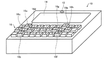
図2は、本実施形態の制御部(コントローラー)10に設けられたキーボードの構成の一例を示す図である。本実施形態の頭部装着型表示装置100は、キーボード16上の一部のキーに文字入力の機能とは異なる機能を割り当て可能に構成されている。
FIG. 2 is a diagram illustrating an example of a configuration of a keyboard provided in the control unit (controller) 10 of the present embodiment. The head-mounted
図2に示す例では、キーボード16上の8個のキー16a〜16hに文字入力の機能とは異なる機能を割り当て可能に構成されている。具体的には、キーボード16上の「W」キー16a、「Z」キー16b、「A」キー16c、「D」キー16dに、上下左右の方向を入力するための方向キー(十字キー)としての機能を割り当て可能に構成され、キーボード上の「I」キー16e、「M」キー16f、「J」キー16g、「L」キー16hに、機能ボタン(ファンクションボタン、例えば、決定ボタン、取り消しボタン等の機能を有するボタン)としての機能を割り当て可能に構成されている。なお、方向キー(十字キー)としての機能を割り当て可能な、前記4個の「W」キー16a、「Z」キー16b、「A」キー16c、「D」キー16dは、「S」キーを中心に、その上下、左右に十字キー配置されている。
In the example shown in FIG. 2, the eight
更に図2に示す例では、これら文字入力の機能とは異なる機能を割り当て可能な8個のキー16a〜16hは、キーの高さ(キートップの高さ)が他のキーよりも高くなるように形成されている。従って、使用者は、これら8個のキー16a〜16hに方向キーや機能ボタンとしての機能が割り当てられた場合に、キーボード16を直視しなくても、これら8個のキー16a〜16hを他のキーと区別して操作することができ、これら8個のキー16a〜16hの操作性を向上することができる。なお、図2に示す例では、8個のキー16a〜16hのキーの高さを略同一としているが、他のキーと区別可能であれば、8個のキー16a〜16hのキーのそれぞれの高さが異なるように構成してもよい。
Further, in the example shown in FIG. 2, the eight
使用者の頭部に装着された状態において使用者に虚像を視認させる構成を有する頭部装着型表示装置100では、虚像を視認しながらキーボード16を直視することが困難である。従って、方向キーや機能ボタンとしての機能が割り当てられた一部のキーの高さやキートップの形状を異ならせることで、当該一部のキーを直視せずに操作できることは、特に頭部装着型表示装置100において有効である。
In the head-mounted
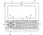
図3は、本実施形態の制御部(コントローラー)10に設けられたキーボードの構成の他の例を示す図である。 FIG. 3 is a diagram illustrating another example of the configuration of the keyboard provided in the control unit (controller) 10 of the present embodiment.
図3に示す例では、図2に示す例と同様に、キーボード16上の4個のキー16a〜16dに、方向キー(十字キー)としての機能を割り当て可能に構成され、4個のキー16e〜16hに、機能ボタン(ファンクションボタン)としての機能を割り当て可能に構成されている。但し、図3の例では、これら文字入力の機能とは異なる機能を割り当て可能な8個のキー16a〜16hは、キートップの形状が他のキーとは異なるように形成されている。具体的には、4個のキー16a〜16dについては、キートップの形状が三角形に形成され、4個のキー16e〜16hについては、キートップの形状が円形に形成されているのに対して、その他のキーについては、キートップの形状が矩形に形成されている。図3のように構成した場合であっても、使用者は、これら8個のキー16a〜16hに方向キーや機能ボタンとしての機能が割り当てられた場合に、キーボード16を直視しなくても、これら8個のキー16a〜16hを他のキーと区別して操作することができ、これら8個のキー16a〜16hの操作性を向上することができる。
In the example shown in FIG. 3, as in the example shown in FIG. 2, functions as direction keys (cross keys) can be assigned to the four
図4は、頭部装着型表示装置100の構成を機能的に示す機能ブロック図である。制御部10は、操作部110(本実施形態では、タッチパッド14、キーボード16、電源スイッチ18)と、記憶部120と、電源130と、CPU140と、インターフェイス180と、送信部(Tx)51、52とを備え、各部は図示しないバスにより相互に接続されている。
FIG. 4 is a functional block diagram functionally showing the configuration of the head-mounted
記憶部120は、ROM、RAM、DRAM、ハードディスク等を含む記憶部である。電源130は、頭部装着型表示装置100の各部に電源を供給する。電源130としては、例えば二次電池を用いることができる。
The
CPU140は、予めインストールされたプログラムを実行することで、オペレーティングシステム(OS)150として機能を提供する。また、CPU140は、ROMやハードディスクに格納されているファームウェアやコンピュータープログラムをRAMに展開して実行することにより、画像処理部160、音声処理部170、表示制御部190、操作制御部192としても機能する。
The
インターフェイス180は、制御部10に対して、コンテンツの供給元となる種々の外部機器OA(例えば、パーソナルコンピューター(PC)や携帯電話端末、ゲーム端末)を接続するためのインターフェイスである。インターフェイス180としては、例えば、USBインターフェイスや、メモリーカード用インターフェイス、無線LANインターフェイス等を備える。コンテンツとは、画像(静止画像、動画像)や音声等からなる情報内容を意味する。
The
画像処理部160は、インターフェイス180を介して入力されるコンテンツに基づき、クロック信号、垂直同期信号、水平同期信号、画像データーを生成し、接続部40を介してこれらの信号を画像表示部20に供給する。具体的には、画像処理部160は、コンテンツに含まれる画像信号を取得する。取得した画像信号は、例えば動画像の場合、一般的に1秒あたり30枚のフレーム画像から構成されているアナログ信号である。画像処理部160は、取得した画像信号から、垂直同期信号や水平同期信号等の同期信号を分離する。また、画像処理部160は、分離した垂直同期信号や水平同期信号の周期に応じて、PLL回路(図示省略)等を利用してクロック信号を生成する。
The
画像処理部160は、同期信号が分離されたアナログ信号を、A/D変換器(図示省略
)を用いてディジタル画像信号に変換する。その後、画像処理部160は、変換後のディジタル画像信号を、対象画像の画像データー(RGBデーター)として、1フレーム毎に記憶部120内のDRAMに格納する。なお、画像処理部160は、必要に応じて、画像データーに対して、解像度変換処理、輝度や彩度の調整といった種々の色調補正処理、キーストーン補正処理等の画像処理を実行してもよい。
The
画像処理部160は、生成したクロック信号、垂直同期信号、水平同期信号、記憶部120内のDRAMに格納された画像データーとを、送信部51、52を介してそれぞれ送信する。なお、送信部51を介して送信される画像データーを「右眼用画像データー」と呼び、送信部52を介して送信される画像データーを「左眼用画像データー」と呼ぶ。送信部51、52は、制御部10と画像表示部20との間におけるシリアル伝送のためのトランシーバーとして機能する。
The
表示制御部190は、右表示駆動部22及び左表示駆動部24を制御する制御信号を生成する。具体的には、表示制御部190は、制御信号により、右LCD制御部211による右LCD241の駆動ON/OFFや、右バックライト制御部201による右バックライト221の駆動ON/OFF、左LCD制御部212による左LCD242の駆動ON/OFFや、左バックライト制御部202による左バックライト222の駆動ON/OFFなどを、個別に制御することにより、右表示駆動部22及び左表示駆動部24のそれぞれによる画像光の生成及び射出を制御する。
The
表示制御部190は、右LCD制御部211及び左LCD制御部212に対する制御信号を送信部51、52を介してそれぞれ送信する。また、表示制御部190は、右バックライト制御部201及び左バックライト制御部202に対する制御信号を送信部51、52を介してそれぞれ送信する。
The
操作制御部192は、操作部110からの検出データーを取得し、取得した検出データーに応じた処理をOS150(例えば、OS150にインストールされた各種アプリケーション)に行わせる。操作制御部192は、キーボード16上の各キーに割り当てる機能を設定し、キーボード16においてキー入力が行われたキーに割り当てられた機能に応じた処理をOS150に行わせる。
The
特に、本実施形態の操作制御部192は、所与の割当変更条件が満たされた場合に、キーボード16上の一部のキー(本実施形態では、8個のキー16a〜16h)に割り当てる機能を、文字入力の機能から、文字入力の機能とは異なる機能に変更する処理を行う。具体的には、操作制御部192は、所与の割当変更条件が満たされたと判断した場合に、4個のキー16a〜16dに割り当てる機能を、方向キー(十字キー)としての機能に変更し、4個のキー16e〜16hに割り当てる機能を、機能ボタン(ファンクションボタン)としての機能に変更する。なお、割当変更条件が満たされ、8個のキー16a〜16hに割り当てる機能を変更した場合には、キーボード上の他のキーの機能を無効とする(当該他のキーに対するキー入力があっても、当該キー入力に応じた処理を行わない)ようにしてもよい。
In particular, the
なお、操作制御部192は、制御部10に設けられた割当変更用の操作キー(図示省略)へのキー入力があった場合に、割当変更条件が満たされたと判断して、キーボード16上の一部のキーに割り当てる機能を特殊キー(方向キーや機能ボタン)の機能に変更し、当該操作キーへの再度のキー入力があった場合に、キーボード16上の全てのキーの機能を文字入力の機能に戻すようにしてもよい。
The
また、操作制御部192は、OS150にインストールされた各種アプリケーションの動作状況に基づき割当変更条件が満たされたか否かを判断してもよい。例えば、方向キーと機能ボタンによる操作を必要とする特定のアプリケーション(例えば、ゲームコントローラーによる操作を必要とするゲーム用アプリケーション)が起動された場合に、割当変更条件が満たされたと判断して、キーボード16上の一部のキーに割り当てる機能を方向キーや機能ボタンの機能に変更してもよい。また、文字入力による操作を必要とする特定のアプリケーション(例えば、メール用アプリケーション)が起動された場合に、キーボード16上の全てのキーに割り当てる機能を文字入力の機能に変更してもよい。
Further, the
また、操作制御部192は、実行中のアプリケーションにおいて、方向キーと機能ボタンによる操作を必要とする状況(例えば、アプリケーションのメニュー画面において、項目を選択して決定或いは取り消しの操作を行う状況)となった場合に、キーボード16上の一部のキーに割り当てる機能を方向キーや機能ボタンの機能に変更し、文字入力による操作を必要とする状況(例えば、Webブラウズ用のアプリケーションにおいて、検索用キーワードを入力する状況)となった場合に、キーボード16上の全てのキーに割り当てる機能を文字入力の機能に変更してもよい。
In addition, the
ここで、表示制御部190は、操作制御部192によってキーボード16上の一部のキーに割り当てる機能が変更された場合に、外界像の視認性を変化させる制御を行ってもよい。具体的には、表示制御部190は、キーボード16上の一部のキーに特殊キーの機能を割り当てる特殊キー優先モードにおいては、画像光の輝度を向上させて使用者に虚像を優先して(或いは、使用者に虚像と外景(外界像)とを重畳した状態で)視認させる(外界像の視認性を低下させる)ように右バックライト221及び左バックライト222の制御を行い、キーボード16上の全てのキーに文字入力の機能を割り当てる文字入力優先モードにおいては、画像光の輝度を低下させて使用者に外景(外界像)を優先して視認させる(外界像の視認性を向上させる)ように右バックライト221及び左バックライト222の制御を行うようにしてもよい。このようにすると、キーボード16を直視しなくても一部のキー(8個のキー16a〜16h)の操作を容易に行うことができる特殊キー優先モードにおいては、虚像を視認させ易くし、キーボード16を直視しなければキー入力を行うことが困難な文字入力優先モードにおいては、外景としてのキーボード16を視認させ易くすることができ、利便性を向上することができる。
Here, when the function assigned to some keys on the
また、表示制御部190は、外界像として視認されるキーボード16と虚像との位置関係に応じて外界像の視認性を変化させる制御を行ってもよい。また、表示制御部190は、操作制御部192によってキーボード16上の一部のキーに文字入力の機能が割り当てられ、且つ、外界像として視認されるキーボード16と虚像とが重複する位置関係である場合に、外界像の視認性を向上させる制御を行ってもよい。例えば、画像表示部20に、使用者の視野方向を撮像する撮像部(カメラ)を設けておき、表示制御部190が、当該撮像部から出力された撮像画像中のキーボードの位置に基づいて、使用者の視野において虚像とキーボードが重複しているかを判断し、虚像とキーボードが重複していると判断した場合に、画像光の輝度を低下させて使用者に外界像を優先して視認させる(外界像の視認性を向上させる)ように右バックライト221及び左バックライト222の制御を行うようにしてもよい。この場合に、表示制御部190は、虚像とキーボードとの重複部分についてのみ外界像の視認性を向上させるように右LCD制御部211及び左LCD制御部212の制御を行うようにしてもよい。このようにすると、文字入力優先モードにおいて、虚像と重なるキーボード16の視認性を向上させることができ、利便性を向上することができる。
The
また、画像処理部160が、タッチパッド14への入力により操作可能なソフトキーボード(仮想キーボード)の画像を生成し、虚像として使用者に視認させるように構成してもよい。例えば、タッチパッド14の入力時には、ソフトキーボードを虚像として表示させ、キーボード16の操作時には、ソフトキーボードを表示させないようにしてもよい。表示制御部190は、タッチパッド14の入力時には、ソフトキーボードが強調表示されるような制御を行ってもよい。また、画像処理部160は、キーボード16上の一部のキーに方向キーの機能を割り当てる特殊キー優先モードにおいて、当該一部のキーの入力時には、当該一部のキーへの入力により操作可能なポインター(例えば、カーソル)の画像を生成し、虚像として使用者に視認させてもよい。
Further, the
音声処理部170は、コンテンツに含まれる音声信号を取得し、取得した音声信号を増幅して、画像表示部20の右イヤホン32及び左イヤホン34に接続部40を介して供給する。
The
画像表示部20は、右表示駆動部22と、左表示駆動部24と、右光学像表示部26を構成する右導光板261と、左光学像表示部28を構成する左導光板262と、右イヤホン32と、左イヤホン34とを備えている。
The
右表示駆動部22は、受信部(Rx)53と、光源として機能する右バックライト(BL)制御部201及び右バックライト221と、表示素子として機能する右LCD制御部211及び右LCD241と、右投写光学系251とを含んでいる。なお、右バックライト制御部201と、右LCD制御部211と、右バックライト221と、右LCD241とを総称して「画像光生成部」と呼ぶ。
The right
受信部53は、制御部10と画像表示部20との間におけるシリアル伝送のためのレシーバーとして機能する。右バックライト制御部201は、入力された制御信号に基づいて、右バックライト221を駆動する機能を有する。右バックライト221は、例えば、LEDやエレクトロルミネセンス(EL)等の発光体である。右LCD制御部211は、受信部53を介して入力されたクロック信号と、垂直同期信号と、水平同期信号と、右眼用画像データーとに基づいて、右LCD241を駆動する機能を有する。右LCD241は、複数の画素をマトリクス状に配置した透過型液晶パネルである。画像光生成部は、右LCD241のマトリクス状に配置された各画素位置に対応する液晶を駆動することによって、右LCD241を透過する光の透過率を変化させることにより、右バックライト221から照射される照明光を画像を表す有効な画像光へと変調する機能を有する。なお、本実施形態の画像光生成部ではバックライト方式を採用しているが、フロントライト方式や反射方式を用いて画像光を生成する構成としてもよい。右投写光学系251は、右LCDから射出された画像光を平行状態の光束にするコリメートレンズにより構成される。右導光板261は、右投写光学系251から射出された画像光を、所定の光路に沿って反射させつつ使用者の右眼REに導く。なお、右投写光学系251と、右導光板261とを総称して「導光部」と呼ぶ。
The receiving
左表示駆動部24は、受信部(Rx)54と、光源として機能する左バックライト(BL)制御部202及び左バックライト222と、表示素子として機能する左LCD制御部212及び左LCD242と、左投写光学系252とを含んでいる。なお、左バックライト制御部202と、左LCD制御部212と、左バックライト222と、左LCD242とを総称して「画像光生成部」と呼ぶ。また、左投写光学系252と、左導光板262とを総称して「導光部」と呼ぶ。右表示駆動部22と左表示駆動部24とは対になっており、左表示駆動部24の各部は、右表示駆動部22で説明した各部と同様の構成及び機能を有するため、詳細な説明は省略する。左導光板262は、左投写光学系252から射出された画像光を、所定の光路に沿って反射させつつ使用者の左眼LEに導く。
The left
図5は、使用者に視認される虚像の一例を示す説明図である。上述のようにして、頭部装着型表示装置100を装着した使用者の両眼に導かれた画像光が使用者の両眼の網膜に結像することにより、使用者は虚像を視認することができる。図5に示すように、頭部装着型表示装置100の使用者の視野VR内には、虚像VIが表示される。また、使用者の視野VRのうち、虚像VIが表示された部分以外については、使用者は、右光学像表示部26及び左光学像表示部28を透過して、外景SC(外界像)を見ることができる。なお、本実施形態の頭部装着型表示装置100では、使用者の視野VRの内の虚像VIが表示された部分についても、虚像VIの背後に外景SCが透けて見えるように構成されている。すなわち、本実施形態の頭部装着型表示装置100では、使用者が虚像VIと外景SC(外界像)とを重畳した状態で視認可能に構成されている。
FIG. 5 is an explanatory diagram illustrating an example of a virtual image visually recognized by the user. As described above, the image light guided to both eyes of the user wearing the head-mounted
本発明は、上述した実施形態に限定されるものではなく、種々の変形が可能である。例えば、本発明は、実施形態で説明した構成と実質的に同一の構成(例えば、機能、方法及び結果が同一の構成、あるいは目的及び効果が同一の構成)を含む。また、本発明は、実施形態で説明した構成の本質的でない部分を置き換えた構成を含む。また、本発明は、実施形態で説明した構成と同一の作用効果を奏する構成又は同一の目的を達成することができる構成を含む。また、本発明は、実施形態で説明した構成に公知技術を付加した構成を含む。 The present invention is not limited to the above-described embodiments, and various modifications can be made. For example, the present invention includes substantially the same configuration (for example, a configuration having the same function, method and result, or a configuration having the same purpose and effect) as the configuration described in the embodiment. In addition, the invention includes a configuration in which a non-essential part of the configuration described in the embodiment is replaced. In addition, the present invention includes a configuration that exhibits the same operational effects as the configuration described in the embodiment or a configuration that can achieve the same object. In addition, the invention includes a configuration in which a known technique is added to the configuration described in the embodiment.
例えば、上記実施形態では、制御部(コントローラー)10と画像表示部20とを別体で構成する場合について説明したが、制御部10を画像表示部20に対して取り付け/取り外し可能に構成してもよい。また、上記実施形態では、本発明を頭部装着型表示装置に適用する場合について説明したが、本発明は、文字入力用の複数のキーが配置されたキーボードを備えた電子機器であれば、どのような電子機器にも適用することができる。
For example, in the above embodiment, the case where the control unit (controller) 10 and the
また、上記実施形態では、文字入力の機能とは異なる機能を割り当てられるキーボード上の一部のキーを他のキーと識別可能に形成する例として、当該一部のキーのキートップの高さ又は形状を他のキーとは異なるように形成する場合について説明したが、本発明はこれに限られず、使用者が直視せずに当該一部のキーを他のキーと識別できれば当該一部のキーをどのように形成してもよい。例えば、当該一部のキーのキートップに、他のキーにはない凹状の窪み又は凸状の突起等を設けてもよいし、当該一部のキーの材質、硬さ、表面の粗さ等を他のキーとは異なるようにしてもよい。また、当該一部のキーの押下方向が他のキーとは異なるように構成してもよい。例えば、当該一部のキーをコントローラー(例えば、キーボードが設けられた腕時計型のコントローラー)の側面に設け、他のキーをコントローラーの表面に設けてもよい。 In the above embodiment, as an example in which some keys on the keyboard to which a function different from the function of character input is assigned are distinguishable from other keys, the height of the key top of the some keys or Although the case where the shape is formed differently from other keys has been described, the present invention is not limited to this, and if the user can identify the part of the key from the other key without looking directly, the part of the key May be formed in any way. For example, the key tops of some of the keys may be provided with concave depressions or projections that are not found on other keys, and the material, hardness, surface roughness, etc. of the some keys. May be different from other keys. Moreover, you may comprise so that the pressing direction of the said one part key may differ from another key. For example, some of the keys may be provided on the side surface of a controller (for example, a wristwatch-type controller provided with a keyboard), and other keys may be provided on the surface of the controller.
10 制御部、12 点灯部、14 タッチパッド、16 キーボード、18 電源スイッチ、20 画像表示部、21 耳掛部、22 右表示駆動部、24 左表示駆動部、26 右光学像表示部、28 左光学像表示部、32 右イヤホン、34 左イヤホン、40 接続部、42 右コード、44 左コード、46 連結部材、48 本体コード、51,52 送信部、53,54 受信部、100 頭部装着型表示装置、110 操作部、120 記憶部、130 電源、160 画像処理部、170 音声処理部、180 インターフェイス、190 表示制御部、192 操作制御部、201 右バックライト制御部、202 左バックライト制御部、211 右LCD制御部、212 左LCD制御部、221 右バックライト、222 左バックライト、241 右LCD、242 左LCD、251 右投写光学系、252 左投写光学系、261 右導光板、262 左導光板
DESCRIPTION OF
Claims (8)
前記キーボードにおいてキー入力されたキーに割り当てられた機能に応じた処理を実行する操作制御部を含み、
前記操作制御部は、
所与の割当変更条件が満たされた場合に、前記キーボード上の一部のキーに割り当てる機能を、文字入力の機能とは異なる機能に変更する処理を行い、
前記キーボード上の一部のキーは、他のキーと識別可能に形成されている、電子機器。 An electronic device including a keyboard on which a plurality of keys for character input are arranged,
An operation control unit that executes processing according to a function assigned to a key input by the keyboard on the keyboard;
The operation controller is
When a given assignment change condition is satisfied, the function assigned to some keys on the keyboard is changed to a function different from the character input function,
An electronic device in which some keys on the keyboard are formed to be distinguishable from other keys.
前記操作制御部は、
所与の割当変更条件が満たされた場合に、前記キーボード上の一部のキーに割り当てる機能を、方向キーとしての機能に変更する処理を行う、電子機器。 The electronic device according to claim 1,
The operation controller is
An electronic device that performs a process of changing a function assigned to some keys on the keyboard to a function as a direction key when a given assignment change condition is satisfied.
前記電子機器は、使用者の頭部に装着された状態において使用者に虚像を視認させる画像表示部を備えた頭部装着型表示装置であり、
前記キーボードは、前記画像表示部を制御するコントローラーに設けられている、電子機器。 The electronic device according to claim 1 or 2,
The electronic device is a head-mounted display device including an image display unit that allows a user to visually recognize a virtual image in a state of being mounted on the user's head,
The keyboard is an electronic device provided in a controller that controls the image display unit.
前記画像表示部は、使用者が前記虚像と外界像とを同時に視認可能に構成され、
前記キーボード上の一部のキーに割り当てる機能が変更された場合に、前記画像表示部における前記外界像の視認性を変化させる制御を行う表示制御部を更に含む、電子機器。 The electronic device according to claim 3,
The image display unit is configured so that a user can view the virtual image and the external image at the same time,
An electronic device further comprising: a display control unit that performs control to change visibility of the external image in the image display unit when a function assigned to some keys on the keyboard is changed.
前記表示制御部は、
前記キーボード上の一部のキーに文字入力の機能が割り当てられた場合には、前記外界像の視認性を向上させる制御を行い、前記キーボード上の一部のキーに文字入力の機能とは異なる機能が割り当てられた場合には、前記外界像の視認性を低下させる制御を行う、電子機器。 The electronic device according to claim 4,
The display control unit
When a character input function is assigned to a part of the keys on the keyboard, control for improving the visibility of the external image is performed, and a part of the keys on the keyboard is different from the function of character input. An electronic device that performs control to reduce the visibility of the external image when a function is assigned.
前記表示制御部は、
前記外界像として視認される前記キーボードと前記虚像との位置関係に応じて前記外界像の視認性を変化させる制御を行う、電子機器。 The electronic device according to claim 4 or 5,
The display control unit
The electronic device which performs control which changes the visibility of the said external image according to the positional relationship of the said keyboard visually recognized as the said external image, and the said virtual image.
前記表示制御部は、
前記キーボード上の一部のキーに文字入力の機能が割り当てられ、且つ、前記外界像として視認される前記キーボードと前記虚像とが重複する位置関係である場合に、前記外界像の視認性を向上させる制御を行う、電子機器。 The electronic device according to claim 6,
The display control unit
Improve visibility of the external image when a character input function is assigned to some keys on the keyboard, and the keyboard and the virtual image viewed as the external image overlap. Electronic devices that perform control.
前記キーボード上の一部のキーは、キーの高さ又はキートップの形状が他のキーとは異なるように形成されている、電子機器。 The electronic device according to any one of claims 1 to 7,
Some of the keys on the keyboard are electronic devices formed such that the key height or key top shape is different from other keys.
Priority Applications (1)
| Application Number | Priority Date | Filing Date | Title |
|---|---|---|---|
| JP2012069218A JP2013201636A (en) | 2012-03-26 | 2012-03-26 | Electronic apparatus |
Applications Claiming Priority (1)
| Application Number | Priority Date | Filing Date | Title |
|---|---|---|---|
| JP2012069218A JP2013201636A (en) | 2012-03-26 | 2012-03-26 | Electronic apparatus |
Publications (1)
| Publication Number | Publication Date |
|---|---|
| JP2013201636A true JP2013201636A (en) | 2013-10-03 |
Family
ID=49521511
Family Applications (1)
| Application Number | Title | Priority Date | Filing Date |
|---|---|---|---|
| JP2012069218A Pending JP2013201636A (en) | 2012-03-26 | 2012-03-26 | Electronic apparatus |
Country Status (1)
| Country | Link |
|---|---|
| JP (1) | JP2013201636A (en) |
-
2012
- 2012-03-26 JP JP2012069218A patent/JP2013201636A/en active Pending
Similar Documents
| Publication | Publication Date | Title |
|---|---|---|
| US9921646B2 (en) | Head-mounted display device and method of controlling head-mounted display device | |
| JP6264871B2 (en) | Information processing apparatus and information processing apparatus control method | |
| JP5884576B2 (en) | Head-mounted display device and method for controlling head-mounted display device | |
| US9965048B2 (en) | Head-mount type display device, control system, method of controlling head-mount type display device, and computer program | |
| JP6111659B2 (en) | Display device and control method of display device | |
| JP6066037B2 (en) | Head-mounted display device | |
| JP6500477B2 (en) | Head-mounted display device, control system, control method of head-mounted display device, and computer program | |
| JP6318596B2 (en) | Information processing apparatus and information processing apparatus control method | |
| JP6427942B2 (en) | Head-mounted display device, control system, and head-mounted display device control method | |
| US20150168729A1 (en) | Head mounted display device | |
| JP6303274B2 (en) | Head-mounted display device and method for controlling head-mounted display device | |
| JP2016004340A (en) | Information distribution system, head-mounted type display device, control method of head-mounted type display device and computer program | |
| JP2013195867A (en) | Head-mounted display device | |
| US20160021360A1 (en) | Display device, method of controlling display device, and program | |
| US20150279110A1 (en) | Head mounted display, and control method for head mounted display | |
| JP5990958B2 (en) | Head-mounted display device | |
| JP6476781B2 (en) | INFORMATION PROCESSING APPARATUS, METHOD FOR CONTROLLING INFORMATION PROCESSING APPARATUS, AND COMPUTER PROGRAM | |
| JP2014154074A (en) | Input device, head-mounted type display device, and method for controlling input device | |
| JP2013201636A (en) | Electronic apparatus | |
| JP6350705B2 (en) | Display device and control method of display device | |
| JP6669183B2 (en) | Head mounted display and control method of head mounted display | |
| JP2017191424A (en) | Head-mounted display device | |
| JP6217772B2 (en) | Head-mounted display device and method for controlling head-mounted display device |