JP2013204751A - クラッチ装置 - Google Patents
クラッチ装置 Download PDFInfo
- Publication number
- JP2013204751A JP2013204751A JP2012075793A JP2012075793A JP2013204751A JP 2013204751 A JP2013204751 A JP 2013204751A JP 2012075793 A JP2012075793 A JP 2012075793A JP 2012075793 A JP2012075793 A JP 2012075793A JP 2013204751 A JP2013204751 A JP 2013204751A
- Authority
- JP
- Japan
- Prior art keywords
- clutch
- cam member
- plate
- movable cam
- spring
- Prior art date
- Legal status (The legal status is an assumption and is not a legal conclusion. Google has not performed a legal analysis and makes no representation as to the accuracy of the status listed.)
- Granted
Links
Images


Landscapes
- Mechanical Operated Clutches (AREA)
- One-Way And Automatic Clutches, And Combinations Of Different Clutches (AREA)
Abstract
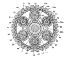
【解決手段】バックトルクリミッタ手段27が、バクトルク発生時に押圧板22A側に向けて移動する円筒状の可動カム部材52を構成要素の一部としてクラッチインナ18Aおよび出力部材11間に設けられるカム機構50を有し、可動カム部材52には、押圧板22Aをクラッチばね24,25のばね力に抗して受圧板21Aから離反する側に押すことを可能とした押圧面73を先端部に有する円筒状の延出部71が、押圧板22A側に延びるようにして一体に設けられる。
【選択図】 図1
Description
14・・・クラッチ装置
16・・・入力部材である一次被動歯車
17・・・クラッチアウタ
18A,18B・・・クラッチインナ
19・・・駆動摩擦板
20・・・被動摩擦板
21A,21B・・・受圧板
22A,22B・・・押圧板
24,25・・・クラッチばね
27・・・バックトルクリミッタ手段
44・・・ばね収容部
50・・・カム機構
51・・・固定カム部材
52・・・可動カム部材
53,54・・・カム歯
61・・・スプライン係合部
71・・・延出部
72・・・フランジ部
73・・・押圧面
74・・・受圧面
75・・・スプライン歯
76・・・切欠き部
77・・・潤滑油孔
Claims (8)
- 入力部材(16)に連結されるクラッチアウタ(17)と、出力部材(11)に連動、連結されるクラッチインナ(18A,18B)と、前記クラッチアウタ(17)に係合される複数枚の駆動摩擦板(19)と、それらの駆動摩擦板(19)と交互に重ね合わされて前記クラッチインナ(18A,18B)に係合される複数枚の被動摩擦板(20)と、複数枚ずつの前記駆動摩擦板(19)および前記被動摩擦板(20)のうち軸方向一端に配置される摩擦板に対向して配置される受圧板(21A,21B)と、複数枚ずつの前記駆動摩擦板(19)および前記被動摩擦板(20)を前記受圧板(21A,21B)との間に挟む押圧板(22A,22B)と、前記駆動摩擦板(19)および前記被動摩擦板(20)を前記受圧板(21A,21B)との間で圧着する側に前記押圧板(22A,22B)を付勢するばね付勢力を発揮するクラッチばね(24,25)と、前記出力部材(11)からの駆動力が前記入力部材(16)からの駆動力を上回るときに前記押圧板(22A,22B)を前記受圧板(21A,21B)から離反する側に動かすバックトルクリミッタ手段(27)とを備えるクラッチ装置において、前記バックトルクリミッタ手段(27)が、前記出力部材(11)からの駆動力が前記入力部材(16)からの駆動力を上回るときに前記クラッチインナ(18A,18B)と独立して前記押圧板(22A,22B)側に向けて移動する円筒状の可動カム部材(52)を構成要素の一部として前記クラッチインナ(18A,18B)および前記出力部材(11)間に設けられるカム機構(50)を有し、前記可動カム部材(52)には、前記押圧板(22A,22B)側に向けての移動時に前記押圧板(22A,22B)に当接して該押圧板(22A,22B)を前記クラッチばね(24,25)のばね力に抗して前記受圧板(21A,21B)から離反する側に押すことを可能とした押圧面(73)を先端部に有する円筒状の延出部(71)が、前記押圧板(22A,22B)側に延びるようにして一体に設けられることを特徴とするクラッチ装置。
- 前記クラッチインナ(18A,18B)内に同軸に配置される前記可動カム部材(52)の外周が、前記クラッチインナ(18A,18B)の内周に、軸方向相対移動可能かつ軸線まわりの相対回転を不能としてスプライン係合されることを特徴とする請求項1記載のクラッチ装置。
- 前記可動カム部材(52)の内周に、前記出力部材(11)に相対回転不能に連結される固定カム部材(51)の外周に設けられる斜歯形状のカム歯(53)に噛合するカム歯(54)が設けられ、前記可動カム部材(52)の内周の前記カム歯(54)の軸方向長さが、前記可動カム部材(52)の外周および前記クラッチインナ(18A,18B)の内周のスプライン係合部(61)の軸方向長さよりも短く設定されることを特徴とする請求項2記載のクラッチ装置。
- 前記押圧板(22A,22B)に、前記クラッチばね(24,25)を収容して前記固定カム部材(51)側に突出する複数の筒状のばね収容部(44)が設けられ、前記延出部(71)の押圧面(73)を当接させることを可能とした受圧面(74)が、前記ばね収容部(44)の外周のうち前記クラッチインナ(18A,18B)の半径方向に沿う外側外周に形成されることを特徴とする請求項3記載のクラッチ装置。
- 前記延出部(71)を含む前記可動カム部材(52)の外周に、平坦な前記押圧面(73)を形成するようにして前記延出部(71)の前記押圧板(22A,22B)側の端部に設けられるフランジ部(72)の外周に外面を面一に連ならせたスプライン歯(75)が、前記クラッチインナ(18A,18B)の内周にスプライン係合するようにして形成されることを特徴とする請求項2〜4のいずれか1項に記載のクラッチ装置。
- 前記ばね収容部(44)の前記固定カム部材(51)側の端部外周のうち前記クラッチインナ(18A,18B)の半径方向に沿う外側外周に、前記延出部(71)を配置するための切欠き部(76)が、段差状の前記受圧面(74)を前記ばね収容部(44)の外周に形成するようにして設けられることを特徴とする請求項4記載のクラッチ装置。
- 前記クラッチインナ(18A)および前記可動カム部材(52)のスプライン係合部(61)に対応する部分で前記延出部(71)を含む前記可動カム部材(52)に、その内、外周面間にわたる潤滑油孔(77)が設けられることを特徴とする請求項2〜6のいずれか1項に記載のクラッチ装置。
- 前記潤滑油孔(77)の少なくとも一部が、前記可動カム部材(52)の内周に設けられるカム歯(54)に対応した位置で前記可動カム部材(52)に設けられることを特徴とする請求項7記載のクラッチ装置。
Priority Applications (4)
| Application Number | Priority Date | Filing Date | Title |
|---|---|---|---|
| JP2012075793A JP5882103B2 (ja) | 2012-03-29 | 2012-03-29 | クラッチ装置 |
| US13/752,727 US9157488B2 (en) | 2012-03-29 | 2013-01-29 | Clutch apparatus |
| DE102013205140.9A DE102013205140B4 (de) | 2012-03-29 | 2013-03-22 | Kupplungsvorrichtung |
| IT000245A ITTO20130245A1 (it) | 2012-03-29 | 2013-03-26 | Dispositivo di innesto. |
Applications Claiming Priority (1)
| Application Number | Priority Date | Filing Date | Title |
|---|---|---|---|
| JP2012075793A JP5882103B2 (ja) | 2012-03-29 | 2012-03-29 | クラッチ装置 |
Publications (3)
| Publication Number | Publication Date |
|---|---|
| JP2013204751A true JP2013204751A (ja) | 2013-10-07 |
| JP2013204751A5 JP2013204751A5 (ja) | 2015-05-14 |
| JP5882103B2 JP5882103B2 (ja) | 2016-03-09 |
Family
ID=49524051
Family Applications (1)
| Application Number | Title | Priority Date | Filing Date |
|---|---|---|---|
| JP2012075793A Expired - Fee Related JP5882103B2 (ja) | 2012-03-29 | 2012-03-29 | クラッチ装置 |
Country Status (1)
| Country | Link |
|---|---|
| JP (1) | JP5882103B2 (ja) |
Cited By (2)
| Publication number | Priority date | Publication date | Assignee | Title |
|---|---|---|---|---|
| JP2015175472A (ja) * | 2014-03-17 | 2015-10-05 | 本田技研工業株式会社 | 多板式摩擦クラッチ |
| CN115628269A (zh) * | 2018-12-05 | 2023-01-20 | 株式会社F.C.C. | 动力传递装置 |
Citations (4)
| Publication number | Priority date | Publication date | Assignee | Title |
|---|---|---|---|---|
| JPS60184721A (ja) * | 1984-03-02 | 1985-09-20 | Suzuki Motor Co Ltd | 自動2輪車の多板摩擦クラツチ |
| JPS62110028A (ja) * | 1985-11-07 | 1987-05-21 | Suzuki Motor Co Ltd | バツクトルク低減装置 |
| JP2009250295A (ja) * | 2008-04-03 | 2009-10-29 | Kawasaki Heavy Ind Ltd | 摩擦クラッチのバックトルク低減装置 |
| JP2010084860A (ja) * | 2008-09-30 | 2010-04-15 | Honda Motor Co Ltd | 多板式クラッチ |
-
2012
- 2012-03-29 JP JP2012075793A patent/JP5882103B2/ja not_active Expired - Fee Related
Patent Citations (4)
| Publication number | Priority date | Publication date | Assignee | Title |
|---|---|---|---|---|
| JPS60184721A (ja) * | 1984-03-02 | 1985-09-20 | Suzuki Motor Co Ltd | 自動2輪車の多板摩擦クラツチ |
| JPS62110028A (ja) * | 1985-11-07 | 1987-05-21 | Suzuki Motor Co Ltd | バツクトルク低減装置 |
| JP2009250295A (ja) * | 2008-04-03 | 2009-10-29 | Kawasaki Heavy Ind Ltd | 摩擦クラッチのバックトルク低減装置 |
| JP2010084860A (ja) * | 2008-09-30 | 2010-04-15 | Honda Motor Co Ltd | 多板式クラッチ |
Cited By (2)
| Publication number | Priority date | Publication date | Assignee | Title |
|---|---|---|---|---|
| JP2015175472A (ja) * | 2014-03-17 | 2015-10-05 | 本田技研工業株式会社 | 多板式摩擦クラッチ |
| CN115628269A (zh) * | 2018-12-05 | 2023-01-20 | 株式会社F.C.C. | 动力传递装置 |
Also Published As
| Publication number | Publication date |
|---|---|
| JP5882103B2 (ja) | 2016-03-09 |
Similar Documents
| Publication | Publication Date | Title |
|---|---|---|
| US8256599B2 (en) | Wave spring holding structure and frictional engagement apparatus | |
| JP4990254B2 (ja) | 多板式クラッチ | |
| JP4939585B2 (ja) | 多板クラッチ装置 | |
| CN110273947B (zh) | 自动变速器 | |
| CN110273946B (zh) | 自动变速器 | |
| JP2014202228A (ja) | トルクダンパ装置 | |
| JP2013096558A (ja) | 発進装置 | |
| JP7518652B2 (ja) | 油圧クラッチの給油構造 | |
| EP4242485B1 (en) | Power transmission device | |
| JP5171779B2 (ja) | 多板クラッチ装置 | |
| US9157488B2 (en) | Clutch apparatus | |
| JP4990253B2 (ja) | 多板式クラッチ | |
| EP2930387B1 (en) | Clutch apparatus | |
| US8272489B2 (en) | Multiple disc clutch | |
| JP5882103B2 (ja) | クラッチ装置 | |
| JP5363385B2 (ja) | 多板式クラッチ | |
| JP5905763B2 (ja) | クラッチ装置 | |
| JP5905762B2 (ja) | クラッチ装置 | |
| CN110273937B (zh) | 自动变速器 | |
| JP6640179B2 (ja) | 内燃機関のクラッチ装置 | |
| JP4929263B2 (ja) | 多板式クラッチ | |
| US20250277514A1 (en) | Clutch device | |
| JP5232096B2 (ja) | 多板クラッチ装置 | |
| JP2011208749A (ja) | エンジンのフライホイール装置 | |
| JP2011208750A (ja) | エンジンのフライホイール装置及びその製造方法 |
Legal Events
| Date | Code | Title | Description |
|---|---|---|---|
| A621 | Written request for application examination |
Free format text: JAPANESE INTERMEDIATE CODE: A621 Effective date: 20141128 |
|
| A521 | Request for written amendment filed |
Free format text: JAPANESE INTERMEDIATE CODE: A523 Effective date: 20150330 |
|
| A977 | Report on retrieval |
Free format text: JAPANESE INTERMEDIATE CODE: A971007 Effective date: 20150716 |
|
| A131 | Notification of reasons for refusal |
Free format text: JAPANESE INTERMEDIATE CODE: A131 Effective date: 20150722 |
|
| A521 | Request for written amendment filed |
Free format text: JAPANESE INTERMEDIATE CODE: A523 Effective date: 20150918 |
|
| TRDD | Decision of grant or rejection written | ||
| A01 | Written decision to grant a patent or to grant a registration (utility model) |
Free format text: JAPANESE INTERMEDIATE CODE: A01 Effective date: 20160106 |
|
| A61 | First payment of annual fees (during grant procedure) |
Free format text: JAPANESE INTERMEDIATE CODE: A61 Effective date: 20160203 |
|
| R150 | Certificate of patent or registration of utility model |
Ref document number: 5882103 Country of ref document: JP Free format text: JAPANESE INTERMEDIATE CODE: R150 |
|
| LAPS | Cancellation because of no payment of annual fees |