JP2013214031A - Image formation device - Google Patents
Image formation device Download PDFInfo
- Publication number
- JP2013214031A JP2013214031A JP2012132227A JP2012132227A JP2013214031A JP 2013214031 A JP2013214031 A JP 2013214031A JP 2012132227 A JP2012132227 A JP 2012132227A JP 2012132227 A JP2012132227 A JP 2012132227A JP 2013214031 A JP2013214031 A JP 2013214031A
- Authority
- JP
- Japan
- Prior art keywords
- intermediate transfer
- image forming
- image
- transfer member
- toner
- Prior art date
- Legal status (The legal status is an assumption and is not a legal conclusion. Google has not performed a legal analysis and makes no representation as to the accuracy of the status listed.)
- Pending
Links
Images



Landscapes
- Dry Development In Electrophotography (AREA)
- Electrostatic Charge, Transfer And Separation In Electrography (AREA)
- Control Or Security For Electrophotography (AREA)
- Color Electrophotography (AREA)
Abstract
【課題】逆回転動作時にトナーが現像器外に飛散または落下しても、次の画像形成動作に落下したトナーが記録媒体に付着することを防止する画像形成装置を提供する。
【解決手段】複数の像担持体3a〜3dと、現像手段9と、中間転写体4と、トナー像を中間転写体に転写する一次転写手段10と、トナー像を記録媒体Sに転写する二次転写手段55と、中間転写体表面を清掃する中間転写体クリーニング手段15と、画像形成動作終了時に現像剤担持体34を画像形成動作中とは逆回転させる制御手段75とを備え、制御手段は記録媒体Sが二次転写位置に到達するまでに中間転写体4が移動する距離Lを求め、逆回転動作終了後において、中間転写体の回転移動方向で最も上流にある中間転写体第1位置PAが二次転写位置から移動距離Lだけ上流の中間転写体第2位置PTよりも下流位置となるように、中間転写体を回転移動させる。
【選択図】図4To provide an image forming apparatus that prevents toner dropped in the next image forming operation from adhering to a recording medium even if the toner is scattered or dropped out of a developing device during a reverse rotation operation.
A plurality of image carriers 3a to 3d, a developing means 9, an intermediate transfer body 4, a primary transfer means 10 for transferring a toner image to an intermediate transfer body, and a toner image transferred to a recording medium S. A second transfer unit 55; an intermediate transfer member cleaning unit 15 that cleans the surface of the intermediate transfer member; and a control unit 75 that rotates the developer carrying member 34 in the reverse direction of the image forming operation when the image forming operation ends. Obtains the distance L by which the intermediate transfer body 4 moves before the recording medium S reaches the secondary transfer position, and after the reverse rotation operation, the intermediate transfer body first located upstream in the rotational movement direction of the intermediate transfer body. The intermediate transfer member is rotationally moved so that the position PA is positioned downstream of the intermediate transfer member second position PT upstream of the secondary transfer position by a movement distance L.
[Selection] Figure 4
Description
本発明は、複写機、ファクシミリ、プリンタ等の画像形成装置に関するものである。 The present invention relates to an image forming apparatus such as a copying machine, a facsimile, and a printer.
現在、様々な産業分野において電子写真方式による複写機、プリンタ、ファクシミリ等の画像形成装置が広く普及している。これらの画像形成装置では、感光体上に画像情報に応じた静電潜像を形成し、その静電潜像を現像装置によりトナーで可視像として現像している。この現像装置では現像ローラの周面にトナー層規制部材の端縁を摺接させることによりトナーの層厚を一定に規制しており、このようにして得られたトナーの可視像を転写紙上に転写後、定着することによって画像濃度が安定した画像形成を行っている。 At present, image forming apparatuses such as copiers, printers, and facsimiles based on electrophotography are widely used in various industrial fields. In these image forming apparatuses, an electrostatic latent image corresponding to image information is formed on a photosensitive member, and the electrostatic latent image is developed as a visible image with toner by a developing device. In this developing device, the edge of the toner layer regulating member is slidably contacted with the peripheral surface of the developing roller to regulate the toner layer thickness to a constant level, and the visible image of the toner thus obtained is transferred onto the transfer paper. After the transfer, the image is formed with a stable image density by fixing.
ところで、電子写真方式の画像形成装置においては、如何なる環境下、如何なる印刷条件下においても、画像濃度が安定していることおよび異常画像の発生が無いことが理想的である。しかし、実際はさまざまな負荷によって、画像濃度の変動や異常画像の発生があり得る。 By the way, in an electrophotographic image forming apparatus, it is ideal that the image density is stable and abnormal images are not generated under any environment and under any printing condition. However, in practice, image density fluctuations and abnormal images may occur due to various loads.
この中の一つに、低画像面積率の画像ばかりを印刷し続けることにより、現像装置内の現像剤としてのトナーあるいは現像剤中のトナーが収支の少ない状態で攪拌による負荷を受け続け、その結果トナーが現像器中で凝集し、現像ローラへの現像剤汲み上げ部の空隙等に堆積して現像剤の汲み上げを阻害し、白スジや白帯のような異常画像が発生する場合がある。 One of them is to continue printing only images with a low image area ratio, so that the toner as a developer in the developing device or the toner in the developer is continuously subjected to a load caused by agitation in a state where the balance is small. As a result, the toner aggregates in the developing unit and accumulates in a gap or the like of the developer pumping portion to the developing roller to inhibit the developer pumping, and an abnormal image such as a white stripe or a white belt may occur.
また、低画像面積率の画像だけに限らず、高温高湿環境下や長時間連続動作など、現像器中やトナーカートリッジ内のトナーが凝集しやすい条件でも、同様に白スジや白帯のような異常画像が発生する場合がある。 In addition, not only images with a low image area ratio, but also white streaks and white belts, even under conditions where the toner in the developing unit or toner cartridge is likely to aggregate, such as in high-temperature and high-humidity environments or for long-term continuous operation. Abnormal images may occur.
このような異常画像の発生や画像劣化に対しては、所定の条件が満足されたとき、現像時における現像ローラや現像スリーブ(現像剤担持体)の第1の方向への回転停止後、第1の方向とは逆の第2の方向に所定の時間だけ逆回転させることで、空隙等に堆積した粗分化したトナーや凝集トナーを除去したり粉砕したりする技術が提案されている(例えば、特許文献1および2参照)。 With respect to the occurrence of such abnormal images and image deterioration, when a predetermined condition is satisfied, after the rotation of the developing roller and the developing sleeve (developer carrier) during development in the first direction is stopped, There has been proposed a technique for removing or pulverizing coarsely divided toner and agglomerated toner accumulated in a gap or the like by rotating in a second direction opposite to the first direction for a predetermined time (for example, Patent Documents 1 and 2).
例えば、特許文献1記載の技術では、所定の条件として、画像形成動作終了時、又は画像形成動作前に現像ローラを画像形成時の周速以下で一定時間、逆回転動作及び正回転動作を行わせて、トナー層規制部材先端部に溜まったトナーを除去している。更に、特許文献2記載の技術では、温度やカートリッジ交換後の累積プリント枚数や平均印字率またはこれらの組み合わせを設定し、これらの条件ごとに予め設定された閾値を超えた後で、現像剤担持体を逆回転させている。
For example, in the technique described in Patent Document 1, as a predetermined condition, a reverse rotation operation and a normal rotation operation are performed for a predetermined time at a speed equal to or lower than a peripheral speed at the time of image formation at the end of the image formation operation or before the image formation operation. Accordingly, the toner accumulated at the tip of the toner layer regulating member is removed. Furthermore, in the technique described in
しかしながら、通常の画像形成中は第1の方向への回転動作を行うことから、現像器は第1の方向への回転動作を重視して設計されるため、現像器(ケーシング)内に現像剤・トナーを保持する機能(現像器外への現像剤・トナーの飛散や落下を防止する機能)が、第2の方向への回転動作(=逆回転動作)では第1の方向への回転動作より多少劣ってしまうこともある。 However, since the rotating operation in the first direction is performed during normal image formation, the developing device is designed with an emphasis on the rotating operation in the first direction, so that the developer is contained in the developing device (casing). -The function to hold the toner (the function to prevent the developer / toner from scattering and dropping out of the developing device) is the rotation operation in the first direction in the rotation operation in the second direction (= reverse rotation operation). It may be slightly inferior.
また、同等の機能を有していても、長時間第1の方向に回転して現像器の開口部近傍に蓄積した現像剤・トナーが、第2の方向に回転した際に現像器内に保持できず飛散してしまい、装置内を汚す可能性がある。 Even if it has an equivalent function, the developer / toner that has been rotated in the first direction for a long time and accumulated in the vicinity of the opening of the developing device will enter the developing device when rotated in the second direction. There is a possibility that the inside of the apparatus may be polluted due to scattering without being held.
特に、このように現像剤担持体(現像ローラ)の逆回転動作時に現像剤・トナーが現像器外に落下し、中間転写ベルト上に落下すると、これら落下物は次に形成する画像上に汚れとして現れてしまう可能性がある。 In particular, when the developer carrying member (developing roller) rotates in the reverse direction as described above, when the developer / toner falls outside the developing unit and falls on the intermediate transfer belt, the fallen object becomes dirty on the image to be formed next. May appear.
上述の特許文献1、2のいずれもがこれら第2の方向への回転動作(=逆回転動作)により蓄積した現像剤・トナーである落下物が装置内を汚す可能性があり、これが中間転写ベルト上に落下すると次に形成する画像上に汚れとして現れてしまう可能性があるとの問題を解消できていない。
In any of the above-mentioned
そこで、本発明は、上述した事情に鑑みてなされたものであり、装置の大型化やコストアップを招くこと無く、現像剤担持体逆回転動作時に現像剤担持体から中間転写体へトナーが飛散または落下した場合でも、次の画像形成動作に飛散または落下したトナーが記録媒体に付着することを防止する画像形成装置を提供することを目的とする。 Therefore, the present invention has been made in view of the above-described circumstances, and the toner is scattered from the developer carrying member to the intermediate transfer member during the reverse rotation operation of the developer carrying member without causing an increase in size and cost of the apparatus. Another object of the present invention is to provide an image forming apparatus that prevents toner that has been scattered or dropped in the next image forming operation from adhering to a recording medium even when it has fallen.
上記目的を達成するために、本発明の画像形成装置は、複数の像担持体と、トナーを表面に付着させた現像剤担持体表面上のトナーで前記像担持体の静電潜像を現像する現像手段と、前記複数の像担持体と順次対向するよう回転移動するベルト状の中間転写体と、前記像担持体のトナー像を中間転写体に一次転写する一次転写手段と、前記中間転写体に一次転写された画像を二次転写位置で前記中間転写体から記録媒体に二次転写する二次転写手段と、画像形成動作後の中間転写体表面を清掃する中間転写体クリーニング手段と、画像形成動作終了時に前記現像剤担持体を画像形成動作中とは逆方向に回転させる制御手段とを備え、前記制御手段は、所定の画像形成モードの駆動開始後に記録媒体先端が二次転写位置に到達するまでに前記中間転写体が回転移動する距離を移動距離としたとき、中間転写体回転移動方向に対して最も上流にある現像手段の下方に位置する中間転写体第1位置が、前記二次転写位置から中間転写体に沿って前記移動距離だけ上流に位置する中間転写体第2位置よりも下流の位置になるように、現像剤担持体逆回転動作終了後に中間転写体を回転移動させることを特徴とする。 In order to achieve the above object, an image forming apparatus of the present invention develops an electrostatic latent image on an image carrier with a plurality of image carriers and toner on the surface of a developer carrier having toner adhered to the surface. Developing means, a belt-like intermediate transfer member that rotates and moves sequentially to face the plurality of image carriers, a primary transfer unit that primarily transfers a toner image of the image carrier to an intermediate transfer member, and the intermediate transfer member A secondary transfer means for secondary transfer of the image primarily transferred to the body from the intermediate transfer body to the recording medium at a secondary transfer position; an intermediate transfer body cleaning means for cleaning the surface of the intermediate transfer body after the image forming operation; Control means for rotating the developer carrying member in a direction opposite to that during the image forming operation at the end of the image forming operation, and the control means is configured such that the leading edge of the recording medium is positioned at the secondary transfer position after the start of the predetermined image forming mode. Before said to reach When the distance that the transfer body rotates is defined as the movement distance, the intermediate transfer body first position located below the developing means that is furthest upstream with respect to the intermediate transfer body rotation direction is the intermediate transfer position from the secondary transfer position. The intermediate transfer member is rotated and moved after the developer carrying member reverse rotation operation is finished so as to be positioned downstream of the second intermediate transfer member position positioned upstream by the moving distance along the body.
本発明によれば、現像剤担持体逆回転動作の終了後に中間転写体を回転移動させるので、現像剤担持体逆回転動作時に、現像剤担持体から中間転写体へトナーが飛散または落下した場合でも、次の画像形成動作に飛散または落下したトナーが記録媒体に付着することを防止できる。 According to the present invention, since the intermediate transfer member is rotated after the developer carrying member reverse rotation operation, the toner is scattered or dropped from the developer carrying member to the intermediate transfer member during the developer carrying member reverse rotation operation. However, it is possible to prevent the toner scattered or dropped in the next image forming operation from adhering to the recording medium.
以下、図を参照して本発明の実施形態を説明する。実施形態及び変形例等に亘り、同一の機能もしくは形状を有する部材や構成部品等の構成要素については、判別が可能な限り同一符号を付すことにより一度説明した後ではその説明を省略する。 Hereinafter, embodiments of the present invention will be described with reference to the drawings. In the embodiments and modifications, components such as members and components having the same function or shape are denoted by the same reference numerals as much as possible, and once described, the description thereof is omitted.
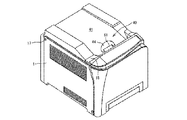
まず、図1及び図2を参照して、本発明の第1の実施形態を適用した画像形成装置の全体構成と共に動作を説明する。図1は、本発明の第1実施形態を適用した画像形成装置の外観斜視図、図2は、その画像形成装置の内部構成の一例を示す概略的な縦断面図である。両図に示した画像形成装置は、回転移動する後述の中間転写体が複数個の画像形成ユニットと順次対向するタンデムタイプのカラー画像形成装置である。 First, with reference to FIG. 1 and FIG. 2, the operation and the overall configuration of the image forming apparatus to which the first embodiment of the present invention is applied will be described. FIG. 1 is an external perspective view of an image forming apparatus to which the first embodiment of the present invention is applied, and FIG. 2 is a schematic longitudinal sectional view showing an example of an internal configuration of the image forming apparatus. The image forming apparatus shown in both figures is a tandem type color image forming apparatus in which an intermediate transfer body, which will be described later, that rotates and moves is sequentially opposed to a plurality of image forming units.
図1及び図2に示す画像形成装置は、装置本体1のほぼ中央に配置され、シートに画像を形成する後述の画像形成手段等を備えた画像形成部2と、この画像形成部2の下方に配置され、画像形成部2にシートもしくはシート状記録媒体の一例としての用紙Sを給送する給紙部20と、画像形成部2にて画像形成された用紙を装置本体1の手前(両図の右側前方であり、装置正面側である)から奥側(両図の左側後方であり、装置背面側である)に排出するシート排出部としてのシート排紙部25と、画像形成部2の上部に配置され、シート排紙部25から排出される用紙を積載するシート積載部(排紙トレイ)40と、を有する。ここで、シートとは、例えば転写紙や記録紙等の用紙(厚紙、はがき、封筒、普通紙、薄紙等を含む)、塗工紙(コート紙やアート紙等を含む)、OHPシートもしくはOHPフィルム、トレーシングペーパ等を含み、画像転写可能な被画像形成媒体を意味する。なお、画像形成部2は用紙Sに画像を記録する画像記録部2とも呼ばれ、シート積載部40は排出されたシートを載置・積載するシート載置部40とも呼ばれる。
The image forming apparatus shown in FIG. 1 and FIG. 2 is disposed almost at the center of the apparatus main body 1 and includes an
画像形成部2には、図2に示すように、像担持体ないし潜像担持体として構成された複数のドラム状の感光体3a,3b,3c,3dを有し、その各感光体3a〜3dには、互いに異なった色のトナー像がそれぞれ形成される。図示した例では、感光体3a〜3dの表面に、イエロートナー像、シアントナー像、マゼンタトナー像及びブラックトナー像がそれぞれ形成される。各感光体3a〜3dは、所定の間隔をあけて互いに平行に配置され、これらの感光体3a〜3dの下部に対向して中間転写体として構成された中間転写ベルト4が配置されている。この無端ベルトからなる中間転写ベルト4は、複数の支持ローラ5,6に巻き掛けられて矢印方向(図2中反時計方向)に駆動される。
As shown in FIG. 2, the
各感光体3a〜3dの周囲の構成は、同様であるため、図2において一番右側に配置されたイエロートナー像が形成される感光体3aを代表して説明する。すなわち、感光体3aには、感光体3aの表面に一様な帯電処理を行う帯電手段としての帯電ローラ7と、画像情報に基づいて感光体3aの表面にレーザ光を照射して静電潜像を形成する光走査装置(LSU)8と、感光体3aの表面に形成された静電潜像を可視像化する現像手段(現像装置)9と、中間転写ベルト4を介して感光体3aと対向配置された第1転写手段(転写装置)10と、中間転写ベルト4に転写後の感光体3aの表面に残留するトナー等を除去するクリーニング手段としてのクリーニングブレード11とがこの順に設けられている。現像装置9の上方には、円筒形状のトナー容器910と補給機構(不図示)が配置され、現像装置9でのトナー消費に応じて補給機構が駆動し、トナー容器910から現像装置9にトナーが供給される。
Since the configuration around each of the
かかる画像形成装置において画像形成が開始されると、感光体3aが図2における時計方向に回転駆動され、この時、帯電ローラ7によって感光体3の表面が所定の極性に一様に帯電される。次いで、その帯電面に、光走査装置8から画像情報に基づくレーザ光が照射され、これによって感光体3aに静電潜像が形成される。そして、感光体3aの表面に形成された静電潜像は、現像装置9によってイエロートナー像として可視像化され、そのイエロートナー像は転写装置10によって中間転写ベルト4上に転写される。
When image formation is started in such an image forming apparatus, the
フルカラー画像形成時は上記した画像形成動作が残りの全ての感光体3b〜3dで同様に行われ、これによって各感光体3a〜3dにそれぞれ形成されたイエロートナー像、シアントナー像、マゼンタトナー像及びブラックトナー像が中間転写ベルト4上に順次重ねて転写される。また、画像形成装置には、中間転写ベルト4を挟んで、支持ローラ6に対向して2次転写ローラ12が配置されている。
一方、画像形成部2の下方に配置された給紙部20には、転写紙、記録紙または樹脂フィルムなどから成るシートとしての用紙Sを積載するシート収容部としての給紙トレイ21と、該給紙トレイ21に積載された用紙Sを送り出す給紙コロ22と、重送された用紙を1枚に分離する分離手段としてのフリクションパッド23等が設けられている。
At the time of full color image formation, the above-described image forming operation is performed in the same manner on all the remaining photoconductors 3b to 3d, whereby yellow toner images, cyan toner images, and magenta toner images respectively formed on the
On the other hand, a
給紙部20から給送された用紙Sは、レジストローラ13に向けて送り出され、その先端が停止しているレジストローラ13に一旦突き当てられて、用紙S先端の斜めずれなどが修正・整合される。この後、レジストローラ13は、中間転写ベルト4上に形成されたカラートナー像が2次転写ローラ12を設けた2次転写部で用紙Sの先端部と合致(接触)するような所定のタイミングで回転を再開し、2次転写ローラ12を備えた2次転写部に向けて記録媒体としての用紙Sを送り出す。
The paper S fed from the
2次転写部で未定着のカラートナー像が転写された用紙Sは、定着手段である定着部(定着装置ともいう)14に送られ、定着部14による加熱・加圧によって未定着のカラートナー像が定着された後、シート排紙部25の排紙ローラ対25a,25bにより装置本体1の上面に設けられたシート積載部40に、画像面が下向き(フェースダウン)で排出・排紙される。上記定着部(定着装置)14は、定着ローラ14a、定着ローラ14aに巻き掛けられた定着ベルト14c、定着ベルト14cを介して定着ローラ14aに圧接する加圧ローラ14bとからなる。定着部14は、上記したものに限らず、ヒータを内蔵したローラ式のもの、また加熱方式もIH(電磁誘導加熱方式)を採用したものなど、適宜採用することができる。なお、カラートナー像転写後の中間転写ベルト4の表面に付着する転写残トナー等は、ベルトクリーニング装置15によって除去され、次の作像・転写工程に備える。なお、これらの画像形成動作は制御手段75により駆動制御されている。
The sheet S on which the unfixed color toner image is transferred in the secondary transfer unit is sent to a fixing unit (also referred to as a fixing device) 14 as a fixing unit, and unfixed color toner is heated and pressed by the fixing
装置本体1の上部には、画像形成部2を覆う上カバー部材としての上カバー18が設けられ、この上カバー18の上面部分をシート積載部40の排紙トレイ(シート積載面)41として用いている。上カバー18の後端側の辺には支持部を設けていない。この構成によって、上カバー18の排紙トレイ41の前後方向幅より長い長尺シートであってもその一部が排紙トレイ41を越えて後側へ垂らすことで支障なくその長尺シートをストックすることができる。
An
また、上カバー18は、図2に示すように、その下部に画像形成部(画像形成手段)2の一部である光走査装置8を支持しており、装置の後端側に設けたヒンジ17を中心に上方へ開放可能に構成されている。この上カバー18は、後述するロック手段としてのロックレバー60によって装置本体1にロックされ、このロックを解除すると揺動・開閉可能な状態になる。そして、図示を省略しているが、上カバー18を反時計方向へ揺動・開放すると、下部の光走査装置8が一緒に揺動上昇され、画像形成ユニットにアクセスすることが可能となり、メンテナンス等を容易に行うことができる。さらに、本例では上カバー18を開放した部分から画像形成部2の感光体3a〜3d、これらの周囲にそれぞれ配置された帯電ローラ7、現像装置9およびクリーニング装置11が一体化された4つのプロセスユニットを交換等のため取り出し・装着可能である。
Further, as shown in FIG. 2, the
なお、上カバー18を開放するときには凹部44から手を差し込み、図示しないねじりコイルばねの前記付勢力に抗してロックレバー60の操作部61を上に持ち上げることにより、ロックレバー60がピン63を中心に時計方向に回転し、ロック爪62が突起64から外れる。そして、そのまま操作部61を持ち上げることで、上カバー18はヒンジ17を中心として揺動される。
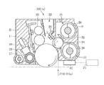
図3は、上記各感光体3a〜3dを備える画像形成ユニットとしてのプロセスユニット(PCU)Ua〜Udの概略断面図である。4プロセスユニットUa〜Udの構成は、同様であるため、図2において一番右側(中間転写体回転移動方向に対して最も上流)に配置されたプロセスユニットUa(符号30としても記す)を例にその構成を詳しく説明する。
When the
FIG. 3 is a schematic cross-sectional view of process units (PCU) Ua to Ud as image forming units including the
図3に示すように、プロセスユニット30は、感光体3a等が装着された感光体ハウジング31と、現像装置9を構成する各種部品が装着された現像ハウジング32(現像器)とを有する。
感光体ハウジング31と現像ハウジング32は、組付け・分離可能に構成されている。また、互いに組み付けられた感光体ハウジング31と現像ハウジング32との間には、図1に示す光走査装置8から感光体3aに照射されるレーザ光を通すレーザ光路空間33が形成されている。
感光体ハウジング31には、感光体3a以外に、帯電ローラ7、帯電ローラの表面をクリーニングする帯電ローラ清掃部材26、クリーニングブレード11、クリーニングブレード11で感光体3aの表面から除去したトナーを図示しない廃トナー回収部へと搬送する廃トナー回収スクリュー27、潤滑剤28、潤滑剤28を削り取って感光体3aの表面に塗布する潤滑剤塗布ブラシ29が装着されている。
As shown in FIG. 3, the
The
In addition to the
一方、現像ハウジング32(現像器)には、現像剤を表面に担持する現像剤担持体としての現像ローラ34、現像剤を供給する供給路35内に配設された供給スクリュー36、現像剤を回収する回収路37内に配設された回収スクリュー38、現像ローラ34の表面に担持される現像剤の厚さを規制する規制部材としてのドクタブレード39、トナーの濃度を検知するトナー濃度センサ42が装着されている。また、本実施形態の現像装置では、トナーとキャリアから成る2成分現像剤を使用している。
On the other hand, the developing housing 32 (developer) is supplied with a developing
ここで、現像装置9内の現像ローラ34は、図3に示すように、時計方向に回転する感光体3aに対し反時計方向であって、感光体3aの周方向の速度の1〜3倍の速度となるように回転することで、感光体3aの静電潜像をトナーで現像している。これに対し、現像ローラ34は後述するように、滞留トナーの排除のため、適時に逆回転し、即ち、その際は時計方向に回転する。この際、現像ローラ34と対向する感光体3aも同時に逆回転し、即ち、感光体3aは反時計方向に回転する。
Here, as shown in FIG. 3, the developing
供給路35内の現像剤は、供給スクリュー36によって搬送され、供給路35の開口部から落下して現像ローラ34上に担持される。現像ローラ34上に担持された現像剤は、ドクタブレード39と現像ローラ34の表面との間の所定の隙間を通過することによって所定の厚さに規制される。そして、現像剤が現像ローラ34と感光体3aとの対向位置(感光体ギャップ)に搬送された際、現像剤のトナーが感光体3aへ静電的に転移して感光体3a上の静電潜像が現像化される。その後、現像ローラ34上の現像剤は回収路37へ回収される。回収路37に回収された現像剤は、回収スクリュー38によって搬送されその搬送方向の下流側で堆積し、堆積した現像剤は図示しない搬送手段によって再び供給路35内へ搬送される。供給路35内では、消費されたトナー量に応じて図示しないトナー補給部を介してトナー容器910(図2参照)からトナーが補給される。また、トナー濃度センサ42によって回収路37内の現像剤のトナー濃度が磁気的に検知され、その検知情報に基づいてトナー濃度調整が行われる。
The developer in the supply path 35 is conveyed by the
図2の現像装置9では、現像ローラ34に供給されトナーを消費した現像剤は、そのまま現像ローラへ繰り返し供給されずに一旦回収され、その後トナーが補給される。すなわち、現像ローラ34には、未使用の現像剤が供給されるか、又は使用後にトナーが補給された現像剤が供給されるため、現像ローラの長手方向の両端において画像の濃度に差異が生じるのを抑制できる。
次に、図2、図4に示すように、感光体3a〜3dや現像装置9を構成する各種部品が装着されたプロセスユニット30の下側には、それら複数のプロセスユニット30(像担持体を収容する)と順次対向するよう回転移動する中間転写体として構成された中間転写ベルト4が配置されている。
In the developing device 9 shown in FIG. 2, the developer that has been supplied to the developing
Next, as shown in FIGS. 2 and 4, a plurality of process units 30 (image carriers) are mounted below the
中間転写ベルト4は、樹脂製であって、一対の支持ローラ5,6である二次転写対向ローラ6とテンションローラ5の間に張架される。中間転写ベルト4は駆動モータM1によって二次転写対向ローラ6が駆動されることで、矢印方向(図2、図4中反時計方向)に回転移動する。感光体3a〜3dは、二次転写対向ローラ6とテンションローラ5の間に張架されている中間転写ベルト4の同一なベルト張架面に接触可能に配置されている。
中間転写ベルト4の内側には、各感光体と対向するように、一次転写部材となる一次転写ローラ10が配置されている。各一次転写ローラ10は加圧部材となるバネによって、中間転写ベルト4を介して各感光体3a〜3dに圧接されている。
The intermediate transfer belt 4 is made of resin and is stretched between the secondary transfer counter roller 6 and the
A
各一次転写ローラ10には、一次転写用の所定の一次転写バイアスが一次転写バイアス印加手段45によって定電流制御で印加されている。中間転写ベルト4のベルト張架面には、中間転写ベルト4の表面に付着している残留トナーや紙粉などを清掃するベルトクリーニング装置15のブレードの先端部が押し当てられている。ベルトクリーニング装置15は、ウレタンゴムなどの弾性部材で構成されていて、二次転写対向ローラ6とイエローの感光体3aとの間に配置されている。このベルトクリーニング装置15と対向する中間転写ベルト4の内側にはローラ46が配置されている。ここで中間転写ベルト4は、ローラ46とベルトクリーニング装置15(クリーニング手段)により挟まれている。
A predetermined primary transfer bias for primary transfer is applied to each
中間転写ベルト4を介して二次転写対向ローラ6と対向する位置には、二次転写部材となる二次転写ローラ12が配置されていて、二次転写部を構成している。二次転写ローラ12には図示しない駆動ギヤによって駆動力が与えられており、二次転写対向ローラ6には二次転写に用いる所定の二次転写バイアスが二次転写バイアス印加手段47によって定電流制御で印加されている。
A
次に、転写手段としての転写装置55は、中間転写ベルト4、一次転写ローラ10、ベルトクリーニング装置15、一次および二次転写バイアス印加手段45,47を備え、これらを制御手段75で制御することで、感光体(像担持体)3aのトナー像を中間転写体として構成された中間転写ベルト4に一次転写し、一次転写されたトナー画像を中間転写ベルト4(中間転写体)から記録媒体としての用紙Sに二次転写するように構成される。
Next, the transfer device 55 as a transfer unit includes an intermediate transfer belt 4, a
次に、この転写装置55と共に本発明の特徴部分を説明する。
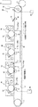
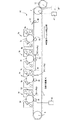
図4は、感光体3a〜3dを備えた各プロセスユニット30(画像形成ユニット)群と中間転写ベルト4(中間転写体)、二次転写ローラ12を拡大した簡略図である。符号PAは現像ローラ34のほぼ真下の位置に相当する中間転写ベルトの位置を示し、これは現像ハウジング32(現像器)外に落ちた現像剤・トナー(以下、「落下トナー」と書く)が中間転写ベルト4(中間転写体)表面に載ってしまう位置であり、この位置を中間転写体第1位置(以下第1位置とも記す)PAとする。
Next, features of the present invention will be described together with the transfer device 55.
FIG. 4 is a simplified enlarged view of each process unit 30 (image forming unit) group including the
ここで、第1位置PAに落下トナーが付着するメカニズムを図3を用いて説明する。
図3に示す現像ローラ34と現像器9のケース(斜線表示している部分)には2箇所のギャップが存在する。一つはドクタブレード39により規制されているギャップ(ドクターギャップ)であり、もう一つは現像ローラ34とケースそのものの間のギャップ(ケースギャップ)である。図示した矢印nは通常の画像形成動作時の現像ローラ34の回転方向であり、現像剤はドクタブレード39に規制されることで一定量がスリーブとともに感光体3とのニップ(現像ニップ)に送られ、さらにケースギャップを通って回収路37内に回収される。このときケースギャップ部分の現像器(現像ケース)32側には現像剤やトナーが微量に堆積する場合がある。順回転動作時にはそれらの堆積物があったとしても現像ローラ34とともに移動する現像剤により現像器中に回収されていく。一方、現像ローラが逆回転(図3に示す矢印nと逆の回転)する際には堆積物が現像剤により現像器外に押し出されることがある。こうして現像器32外に押し出された現像剤やトナーは、現像ケースと感光体3の隙間を通って中間転写ベルト4上の第1位置PAに直接落下したり、もしくはいったん対向する感光体3表面に付着した後に一次転写部で中間転写ベルト4に一部が付着する可能性がある。
Here, the mechanism by which the dropped toner adheres to the first position PA will be described with reference to FIG.
There are two gaps in the case of the developing
このようにして第1位置PAに落下したトナーは、次の画像形成動作で画像領域に入ってしまい記録媒体に汚れとして出てしまうことが懸念される。
具体的には、落下トナーが存在する第1位置PAが、図4に示すように、中間転写体第2位置(以下第2位置とも記す)PTよりも上流にある場合に画像領域に入る可能性が生じる。
There is a concern that the toner that has fallen to the first position PA in this manner enters the image area in the next image forming operation and comes out as a stain on the recording medium.
Specifically, as shown in FIG. 4, the first position PA where the falling toner is present can enter the image area when it is upstream of the intermediate transfer body second position (hereinafter also referred to as the second position) PT. Sex occurs.
ここで、中間転写体第2位置PTとは、最もファーストプリントタイムが短い画像形成動作モードにおいて、シート状の記録媒体としての用紙Sの1枚目の先端と二次転写部(二次転写ニップ)で接触することになる中間転写ベルト4表面部分の、画像形成動作開始前の位置である。二次転写ニップから第2位置PTまでの中間転写ベルト4表面上の距離であり、中間転写ベルト4が第2位置PTより二次転写部に回転移動する移動距離をL(図4では破線で示した)とすると、L=(中間転写ベルト4の移動速度)×(中間転写ベルト4が回転開始〜記録媒体先端が二次転写ニップに到達の時間)と表される。第2位置PTよりも中間転写ベルト4の回転移動方向下流(図4の中間転写ベルト上部では左側)に落下トナーが位置する場合は、落下トナーは記録媒体よりも先に二次転写ニップに到達するため、記録媒体表面に転写されて汚れとなる虞はない。 Here, the intermediate transfer member second position PT means the first leading edge of the sheet S as the sheet-like recording medium and the secondary transfer portion (secondary transfer nip) in the image forming operation mode with the shortest first print time. This is the position of the surface portion of the intermediate transfer belt 4 to be contacted in step) before starting the image forming operation. This is the distance on the surface of the intermediate transfer belt 4 from the secondary transfer nip to the second position PT, and the distance that the intermediate transfer belt 4 rotates from the second position PT to the secondary transfer portion is indicated by L (indicated by the broken line in FIG. 4). L = (moving speed of the intermediate transfer belt 4) × (time when the intermediate transfer belt 4 starts rotating to the time when the leading edge of the recording medium reaches the secondary transfer nip). When the falling toner is located downstream of the second position PT in the rotational movement direction of the intermediate transfer belt 4 (left side in the upper portion of the intermediate transfer belt in FIG. 4), the falling toner reaches the secondary transfer nip before the recording medium. Therefore, there is no possibility of being transferred to the surface of the recording medium and becoming dirty.
次に、制御手段75が行う中間転写体の回転制御機能を説明する。
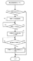
図5には本発明の一例に係る中間転写体の回転制御のフローチャートであり、ステップs1で画像形成装置の画像形成動作が終了して現像ローラの正転による感光体上の現像が終了した後で、ステップs2では現像ローラ34を逆転させる。次いで、ステップs3では、現像ローラ34の停止を待ち、ステップs4に進む。ステップs4では、現像ローラ34の逆回転により落下トナーが中間転写ベルト4表面に落ちてしまう可能性のある箇所のうち最も上流に位置する箇所、すなわち第1位置PAが、第2位置PTよりも中間転写ベルト4の回転移動方向上流に存在する場合(図4ではPAa,PAbが存在する)には、画像形成動作終了後に第1位置PAが第2位置PTよりも下流の位置になるように、同下流の位置を保持できる修正量daだけ移動するように中間転写ベルト4を回転させる。
次いで、ステップs5では、中間転写ベルト4を修正量daだけ移動すると、ステップs6に進み、ここで、中間転写ベルト4の修正移動を停止し、待機状態に入り、ここでの制御を終了する。
Next, the rotation control function of the intermediate transfer member performed by the control means 75 will be described.
FIG. 5 is a flowchart of the rotation control of the intermediate transfer member according to an example of the present invention. After the image forming operation of the image forming apparatus is completed in step s1 and the development on the photosensitive member is completed by the forward rotation of the developing roller. In step s2, the developing
Next, in step s5, when the intermediate transfer belt 4 is moved by the correction amount da, the process proceeds to step s6, where the correction movement of the intermediate transfer belt 4 is stopped, the standby state is entered, and the control here is terminated.
このように、次の画像形成モードでの駆動に先立ち、あらかじめ第1位置PAに存在していた落下トナーを記録媒体と接触する可能性のない位置に移動させることになるため、落下トナーによる用紙(記録媒体)Sの汚れを回避することができる。なお、この際,中間転写ベルト4に接触している感光体3は、摩擦による傷防止のため中間転写ベルト4進行方向と同じ向きに略等速で回転させておくことが望ましい。
As described above, prior to driving in the next image forming mode, the falling toner previously present at the first position PA is moved to a position where there is no possibility of contact with the recording medium. (Recording medium) Staining of S can be avoided. At this time, it is desirable that the
説明を追加すると、現像手段が中間転写体の略上方にある場合、現像器外に落ちた現像剤、トナー(以下落下トナーとも記す)は中間転写体表面の中間転写体第1位置PAに載ってしまう。この第1位置PAが次の画像形成モードで形成する画像を二次転写する用紙Sに接触する位置に相当した場合、この第1位置PAに載っていた落下トナーが記録媒体に重なり、汚れとして付着してしまう。
そこで、現像剤担持体逆転動作終了後において、制御手段75は第1位置PAに載っている落下トナーが中間転写体第2位置PTよりも下流に位置するように中間転写体を回転移動させておくことで、汚れの付着を回避できる。なぜなら、中間転写体第2位置PTは、次の画像形成モードでの画像形成動作で最初に二次転写部に供給される記録媒体の先端位置に相当する(重なる)場所であるため、それよりも下流にあらかじめ落下トナーを運んでおくこと(回転移動しておくこと)で、落下トナーが記録媒体に接触することなく中間転写体クリーニング手段に回収されるからである。
To add a description, when the developing means is substantially above the intermediate transfer member, the developer and toner that have fallen out of the developing device (hereinafter also referred to as falling toner) are placed on the intermediate transfer member first position PA on the surface of the intermediate transfer member. End up. When the first position PA corresponds to a position where the image formed in the next image forming mode is in contact with the sheet S on which secondary transfer is performed, the fallen toner placed on the first position PA overlaps the recording medium and becomes dirty. It will stick.
Therefore, after completion of the developer carrier reverse operation, the control means 75 rotates and moves the intermediate transfer member so that the fallen toner placed on the first position PA is located downstream of the intermediate transfer member second position PT. By attaching, dirt adhesion can be avoided. This is because the intermediate transfer member second position PT is a place corresponding to (overlapping) the leading end position of the recording medium that is first supplied to the secondary transfer unit in the image forming operation in the next image forming mode. This is also because the fallen toner is carried (rotated and moved) in advance downstream so that the fallen toner is collected by the intermediate transfer member cleaning means without contacting the recording medium.
このように、本発明は第1位置PAが第2位置PTよりも上流に位置するようなレイアウトの画像形成装置に適用した際に、現像器中でトナーが凝集し異常画像が発生することを防止するために行う現像剤担持体逆回転動作の終了後に中間転写体を回転移動させ、即ち、中間転写体上の落下トナーを記録媒体と接触する可能性のない位置に移動させるので、現像剤担持体逆回転動作時に、現像手段の現像器外に現像剤・トナーが飛散・落下した場合でも、次の画像形成動作に記録媒体と落下トナー等が重なることを排除できるので、次に形成する画像への汚れ付着を回避することができる。
なお、第1位置PAが第2位置PTよりも下流に位置するのであれば、そもそも記録媒体表面に汚れが付着する虞がない。
As described above, when the present invention is applied to an image forming apparatus having a layout in which the first position PA is located upstream of the second position PT, the toner aggregates in the developing device and an abnormal image is generated. The developer transfer member is rotated in order to prevent the intermediate transfer member from rotating, that is, the falling toner on the intermediate transfer member is moved to a position where there is no possibility of contact with the recording medium. Even when the developer or toner is scattered or dropped outside the developing device of the developing means during the reverse rotation of the carrier, it is possible to eliminate the overlap of the recording medium and the dropped toner in the next image forming operation. It is possible to avoid adhesion of dirt to the image.
In addition, if the first position PA is located downstream of the second position PT, there is no possibility that dirt is attached to the surface of the recording medium.
次に、第1位置PAが第2位置PTよりも上流に位置するようなレイアウトの画像形成装置であっても、第1位置PAに対応する位置の現像ローラ34が逆回転しない画像形成動作モードであれば実施する必要がない。
そこで本発明の第2実施形態としての画像形成装置では、図6に示すように、そこで使用するブラック画像形成ユニットUdを、全ての画像形成ユニットUa〜Ud群の中で最も下流に配置し、残りの画像形成ユニットUa〜Ucの一次転写部材10を移動手段80により定常位置H0より退却位置H1に変位可能に形成する。
Next, even if the image forming apparatus has a layout in which the first position PA is located upstream of the second position PT, the image forming operation mode in which the developing
Therefore, in the image forming apparatus as the second embodiment of the present invention, as shown in FIG. 6, the black image forming unit Ud used there is arranged at the most downstream of all the image forming units Ua to Ud, The
ここで、移動手段80は、図6に示すように、軸80aを中心にして揺動可能に設けられた基板81と、基板81を対向位置へと付勢するバネ82と、定常位置H0より退却位置H1へと基板81を変位させる図示しない駆動源とを備えている。図示しない駆動源としてはモータと歯車機構あるいは電磁ソレノイドなどが挙げられる。
本形態では、基板81に、一次転写ローラ10と加圧ローラ83を配置して、一次転写ローラ10が退却位置H1へと移動する際に、加圧ローラ83も一緒に変位させて中間転写ベルト4が感光体3a〜3cから離間するように構成している。
Here, as shown in FIG. 6, the moving means 80 includes a substrate 81 provided so as to be swingable about a
In the present embodiment, the
ここで、本実施形態に係る画像形成装置は、プロセスユニット(PCU)Ua〜Udのうちブラック色のプロセスユニットUdのみを用いて画像形成動作を行うモノクロモードと、プロセスユニット(PCU)Ua〜Udを用いて画像形成動作を行うカラーモードと、を備える。
前記制御手段75は、モノクロモードでの画像形成動作後の現像ローラ34逆回転動作では、現像ローラ34逆回転動作後の中間転写ベルト4の回転移動を行わないよう制御する。
ここで、モノクロモードではブラックの画像形成ユニットのみを動作させればよいため、落下トナーもブラックでしか発生する可能性がない。更に、現像ローラ34の逆回転もブラックについてのみ行えばよい。
このとき、ブラック現像器9dの下方に落下トナーが落ちる可能性はあるが、次の条件のときには記録媒体を汚す虞はない。
すなわち、図7に示すように、帯電ローラ7dから一次転写ニップまでの感光体表面距離l1が、落下トナー位置から一次転写ニップまでの中間転写ベルト表面距離l2よりも長い場合である。
すなわち、次の画像形成動作を開始する際には、像担持体の帯電⇒露光(潜像書き込み)⇒現像⇒像担持体上のトナー像を中間転写体に一次転写、というプロセスを経る必要があるが、このプロセスを実行している間に、中間転写体は少なくとも帯電〜一次転写の距離(像担持体表面に沿って測った距離)以上回転するため、現像剤担持体逆回転動作後の中間転写体の回転動作を行わずとも、記録媒体に落下トナーが接触することはない。
Here, the image forming apparatus according to this embodiment includes a monochrome mode in which an image forming operation is performed using only the black process unit Ud among the process units (PCU) Ua to Ud, and the process units (PCU) Ua to Ud. And a color mode in which an image forming operation is performed using.
The
Here, in the monochrome mode, it is only necessary to operate the black image forming unit, so that the falling toner can be generated only in black. Further, the reverse rotation of the developing
At this time, the falling toner may fall below the black developing
That is, as shown in FIG. 7, the photosensitive member surface distance l1 from the charging roller 7d to the primary transfer nip is longer than the intermediate transfer belt surface distance l2 from the falling toner position to the primary transfer nip.
That is, when starting the next image forming operation, it is necessary to go through a process of charging the image carrier ⇒ exposure (latent image writing) ⇒ development ⇒ primary transfer of the toner image on the image carrier to the intermediate transfer member. However, during this process, the intermediate transfer member rotates at least the distance from the charge to the primary transfer (the distance measured along the surface of the image carrier). Even if the intermediate transfer member is not rotated, the falling toner does not contact the recording medium.
したがって、モノクロモードでは、現像器中でトナーが凝集し異常画像が発生することを防止するために行う現像剤担持体逆回転動作後の中間転写体の回転移動は無駄となるので、これを排除し、お待たせ(待機)時間の発生頻度を抑えることができ、必要な時しかやらないようにできる。これにより、お待たせ時間の低減、像担持体を含む集合体である画像形成ユニット(PCU)や中間転写体の長寿命化を図れる。 Therefore, in the monochrome mode, the rotational movement of the intermediate transfer member after the reverse operation of the developer carrying member to prevent the toner from aggregating in the developing device and the occurrence of an abnormal image is wasted. In addition, the frequency of waiting (standby) time can be reduced, and it can be done only when necessary. As a result, the waiting time can be reduced, and the life of the image forming unit (PCU), which is an aggregate including the image carrier, and the intermediate transfer member can be extended.
次に、本発明の第3実施形態としての画像形成装置では、図8に示すように、イエローの画像形成ユニットUaを最上流に置き、第1位置PAの代わりに中間転写体第1’位置(第1’位置とも記す)PA’をマゼンタの画像形成ユニットUbとして、第1実施形態と同等の動作を行うことで、画像形成動作後の落下トナーを回避するための中間転写ベルト4の修正量da’を短くすることができる。イエロー単色が人間の目には見えづらいため、ごく微量の落下トナーを汚れとして認識しづらいため、一つ下流の色(シアンやマゼンタ)を対象とすることで、記録媒体にトナー汚れを認識しない状態を実現できる。
即ち、イエロー単色の落下トナーのような小さな点は画像上問題になりにくい。そこでイエローを最上流色として、落下トナーを回避する対象からイエローを除くことで、現像剤担持体逆回転動作後の中間転写体の修正量da’を短くすることができる。
この場合、現像器9中でトナーが凝集し異常画像が発生することを防止するために行う現像剤担持体逆回転動作後の中間転写体の回転移動によるお待たせ(待機)時間を低減できる。
Next, in the image forming apparatus according to the third embodiment of the present invention, as shown in FIG. 8, the yellow image forming unit Ua is placed on the most upstream side, and the intermediate transfer body 1 ′ position is used instead of the first position PA. The intermediate transfer belt 4 is corrected to avoid falling toner after the image forming operation by performing the same operation as that of the first embodiment with PA ′ (also referred to as the first ′ position) as a magenta image forming unit Ub. The quantity da ′ can be shortened. Since it is difficult for human eyes to see a single yellow color, it is difficult to recognize a very small amount of falling toner as dirt. The state can be realized.
In other words, a small point such as a yellow single color falling toner is unlikely to cause a problem on an image. Therefore, the correction amount da ′ of the intermediate transfer member after the developer carrying member reverse rotation operation can be shortened by setting yellow as the most upstream color and removing yellow from the target for avoiding the falling toner.
In this case, it is possible to reduce the waiting (standby) time due to the rotational movement of the intermediate transfer member after the developer carrying member reverse rotation operation is performed in order to prevent the toner from aggregating in the developing device 9 to generate an abnormal image. .
さらに、上述の第1実施形態および第3実施形態の変形例としての画像形成装置では、図6に示すように、現像ローラ34逆回転動作後の中間転写ベルト4の回転移動は、感光体3a〜3cを中間転写ベルト4から離間させた状態で行うとともに、中間転写ベルト4の回転移動を行うとき、中間転写ベルト4から離間させた感光体3a〜3cを回転させないようにしている。
本変形例では、プロセスユニット(PCU)Ua〜Udを用いて画像形成動作を行うカラーモードの画像形成動作後の中間転写ベルト4回転動作は、移動手段80により感光体3a〜3cを中間転写ベルト4から離間させた状態で行う。この場合、感光体3a〜3cを回転させずにすむため、感光体走行距離を減らすことができ、ブラック画像形成ユニットUd以外のカラー画像形成ユニット(PCU)の長寿命化を図れる。この場合、中間転写ベルト4の回転動作は、感光体3a〜3cと中間転写ベルト4の離間が完了してから開始する。
なお、移動手段80により感光体3a〜3dの全てを中間転写ベルト4から離間させるよう構成し、画像形成動作後の中間転写ベルト4の回転動作を、感光体3a〜3dの全てを中間転写ベルト4から離間させた状態で行うようにしてもよい。この場合、全ての感光体3a〜3dを回転させずにすむため、感光体走行距離を減らすことができる。
Further, in the image forming apparatus as a modification of the first embodiment and the third embodiment described above, as shown in FIG. 6, the rotational movement of the intermediate transfer belt 4 after the reverse rotation operation of the developing
In this modification, the intermediate transfer belt 4 rotates after the color mode image forming operation in which the image forming operation is performed using the process units (PCU) Ua to Ud. 4 in a state separated from 4. In this case, since it is not necessary to rotate the
The moving means 80 is configured to separate all of the
次に、本発明の第1実施形態の他の変形例としての画像形成装置を説明する。落下トナーが直接記録媒体表面に接触しない場合でも、記録媒体が二次転写ニップに到達する前に落下トナーの一部が中間転写ベルト4から二次転写ローラ12に転移していると、その後二次転写ローラ12から記録媒体裏面にトナー汚れとして付着する可能性もある。
そこで、落下トナーが落ちている可能性がある第1位置PAa〜PAd(図8参照)が二次転写ニップに到達するタイミングでは二次転写部に通常の画像形成時と逆極性のバイアスを二次転写バイアス印加手段47’により印加することで、落下トナーの二次転写ローラ12への付着を防止できる。ここで、バイアスは二次転写ローラ12に印加する場合はトナー帯電極性と逆極性を、支持ローラ6に印加する場合はトナー帯電極性と同極性を二次転写バイアス印加手段47’’で印加すればよい。
落下トナーが二次転写手段と接触する際に通常の画像形成動作時とは逆極性のバイアスを印加することで落下トナーが二次転写ローラ(二次転写手段)12に付着しないため、二次転写ローラ12から記録媒体裏面への僅かな落下トナー付着による汚れも発生しない。
次に、本発明の第1実施形態の他の変形例としての画像形成装置を説明する。 さらに、第1位置PAa〜PAdが二次転写ニップに到達するよりも前に二次転写ローラ12を中間転写ベルト4から離間しておく(図8の2点鎖線参照)。これにより、落下トナーの二次転写ローラ12への付着を防止できる。
落下トナーが二次転写ローラ(二次転写手段)12の位置に到達する際に二次転写ローラ12を中間転写体から離間する。これにより落下トナーが二次転写手段に付着しないため、二次転写手段から記録媒体の裏面への僅かな落下トナー付着による汚れの発生を防止できる。
なお、図1の画像形成装置で用いたと同様の構成を他の印刷装置や、ファクシミリに適用してもよく、またはそれらを含む複合機からなる他の画像形成装置に適用してもよい。これらの各実施形態の場合も、図1の画像形成装置と同様の効果を得ることができる。
Next, an image forming apparatus as another modification of the first embodiment of the present invention will be described. Even when the falling toner does not directly contact the surface of the recording medium, if a part of the falling toner is transferred from the intermediate transfer belt 4 to the
Therefore, at the timing when the first positions PAa to PAd (see FIG. 8) where the falling toner may be dropped reach the secondary transfer nip, a bias having a polarity opposite to that at the time of normal image formation is applied to the secondary transfer portion. By applying it by the secondary transfer bias applying means 47 ′, it is possible to prevent the fallen toner from adhering to the
Since the falling toner does not adhere to the secondary transfer roller (secondary transfer unit) 12 by applying a bias having a polarity opposite to that during the normal image forming operation when the falling toner comes into contact with the secondary transfer unit, There is no contamination due to a slight drop of toner adhering from the
Next, an image forming apparatus as another modification of the first embodiment of the present invention will be described. Further, the
When the falling toner reaches the position of the secondary transfer roller (secondary transfer means) 12, the
The configuration similar to that used in the image forming apparatus in FIG. 1 may be applied to other printing apparatuses and facsimiles, or may be applied to other image forming apparatuses including a multi-function peripheral including them. In each of these embodiments, the same effect as that of the image forming apparatus of FIG. 1 can be obtained.
3a〜3d 感光体(像担持体)
4 中間転写ベルト(中間転写体)
9 現像装置(現像手段)
10 一次転写ローラ
14 定着部
15 ベルトクリーニング装置
30(Ua〜Ud) プロセスユニット
34 現像ローラ(現像剤担持体)
45,47 一次および二次転写バイアス印加手段
55 転写手段としての転写装置
75 制御手段
L 第2位置より二次転写部までの移動距離
S 記録媒体としての用紙
PA 中間転写体第1位置
PA’ 中間転写体第1’位置
PT 中間転写体第2位置
3a to 3d photoconductor (image carrier)
4 Intermediate transfer belt (intermediate transfer member)
9 Developing device (Developing means)
DESCRIPTION OF
45, 47 Primary and secondary transfer bias application means 55 Transfer device as transfer means 75 Control means L Movement distance from second position to secondary transfer portion S Paper as recording medium PA Intermediate transfer body first position PA 'Intermediate 1st position of transfer body PT 2nd position of intermediate transfer body
Claims (6)
トナーを表面に付着させた現像剤担持体表面上のトナーで前記像担持体の静電潜像を現像する現像手段と、
前記複数の像担持体と順次対向するよう回転移動するベルト状の中間転写体と、
前記像担持体のトナー像を中間転写体に一次転写する一次転写手段と、
前記中間転写体に一次転写された画像を二次転写位置で前記中間転写体から記録媒体に二次転写する二次転写手段と、
画像形成動作後の中間転写体表面を清掃する中間転写体クリーニング手段と、
画像形成動作終了時に前記現像剤担持体を画像形成動作中とは逆方向に回転させる制御手段とを備え、
前記制御手段は、所定の画像形成モードの駆動開始後に記録媒体先端が二次転写位置に到達するまでに前記中間転写体が回転移動する距離を移動距離としたとき、中間転写体回転移動方向に対して最も上流にある現像手段の下方に位置する中間転写体第1位置が、前記二次転写位置から中間転写体に沿って前記移動距離だけ上流に位置する中間転写体第2位置よりも下流の位置になるように、現像剤担持体逆回転動作終了後に中間転写体を回転移動させることを特徴とする画像形成装置。 A plurality of image carriers;
Developing means for developing the electrostatic latent image of the image carrier with toner on the surface of the developer carrier having the toner adhered thereto;
A belt-like intermediate transfer member that rotates and moves so as to sequentially face the plurality of image carriers;
Primary transfer means for primarily transferring the toner image of the image carrier to an intermediate transfer member;
Secondary transfer means for secondary transfer of the image primarily transferred to the intermediate transfer body from the intermediate transfer body to a recording medium at a secondary transfer position;
Intermediate transfer member cleaning means for cleaning the surface of the intermediate transfer member after the image forming operation;
Control means for rotating the developer carrying member in a direction opposite to that during the image forming operation at the end of the image forming operation;
When the distance that the intermediate transfer member rotates until the leading edge of the recording medium reaches the secondary transfer position after the start of driving in a predetermined image forming mode is defined as the movement distance, On the other hand, the first intermediate transfer member position located below the most upstream developing unit is downstream from the second intermediate transfer member position positioned upstream from the secondary transfer position by the moving distance along the intermediate transfer member. An image forming apparatus characterized in that the intermediate transfer member is rotationally moved after the developer carrying member reverse rotation operation is finished so as to be in the position.
前記中間転写体は、前記像担持体と前記現像手段とを備える画像形成ユニットの複数個と前記中間転写体の回転移動方向において順次対向し、
前記中間転写体回転移動方向において最も下流にある画像形成ユニットはブラック色の画像を形成するブラック画像形成ユニットであり、
複数個の前記画像形成ユニットのうち前記ブラック画像形成ユニットのみを用いて画像形成動作を行うモノクロモードと、複数個の前記画像形成ユニットを用いて画像形成動作を行うカラーモードと、を備え、
前記制御手段は、前記モノクロモードでの画像形成動作後の現像剤担持体逆回転動作では、前記現像剤担持体逆回転動作後の中間転写体の回転移動を行わない、ことを特徴とする画像形成装置。 The image forming apparatus according to claim 1.
The intermediate transfer member sequentially faces a plurality of image forming units including the image carrier and the developing unit in the rotational movement direction of the intermediate transfer member,
The image forming unit at the most downstream side in the intermediate transfer member rotational movement direction is a black image forming unit that forms a black image,
A monochrome mode for performing an image forming operation using only the black image forming unit among the plurality of the image forming units, and a color mode for performing an image forming operation using the plurality of the image forming units;
The control means does not rotate the intermediate transfer member after the developer carrying member reverse rotation operation in the developer carrying member reverse rotation operation after the image forming operation in the monochrome mode. Forming equipment.
前記中間転写体は、前記像担持体と前記現像手段とを備える画像形成ユニットの複数個と前記中間転写体の回転移動方向において順次対向し、
複数個の前記画像形成ユニットを用いる画像形成動作後の前記現像剤担持体逆回転動作後の前記中間転写体の回転移動は、前記複数の像担持体のうちの一部または全ての像担持体を前記中間転写体から離間させた状態でおこなうとともに、
前記中間転写体の回転移動をおこなうとき、前記中間転写体から離間させた前記一部または全ての像担持体を回転させないことを特徴とする画像形成装置。 The image forming apparatus according to claim 1.
The intermediate transfer member sequentially faces a plurality of image forming units including the image carrier and the developing unit in the rotational movement direction of the intermediate transfer member,
The rotational movement of the intermediate transfer member after the developer carrying member reverse rotation operation after the image forming operation using a plurality of the image forming units is a part or all of the plurality of image carriers. In a state of being separated from the intermediate transfer member,
An image forming apparatus, wherein when the intermediate transfer member is rotated, a part or all of the image carrier separated from the intermediate transfer member is not rotated.
前記中間転写体の回転移動方向に対して最も上流にある画像形成ユニットはイエロー色の画像を形成するイエロー画像形成ユニットであり、
前記制御手段は、上流から2番目の画像形成ユニットの現像手段の下方に位置する中間転写体第1’位置が前記中間転写体第2位置よりも下流の位置になるように、現像剤担持体逆回転動作終了後に中間転写体を回転移動させる、ことを特徴とする画像形成装置。 The image forming apparatus according to claim 1,
The most upstream image forming unit with respect to the rotational movement direction of the intermediate transfer member is a yellow image forming unit that forms a yellow image.
The control means includes a developer carrier so that an intermediate transfer body first position located below the developing means of the second image forming unit from the upstream is positioned downstream of the intermediate transfer body second position. An image forming apparatus, wherein the intermediate transfer member is rotated after the reverse rotation operation is completed.
前記中間転写体第1位置または第1’位置が前記二次転写部を通過する際には、前記二次転写手段に画像形成動作時とは逆極性のバイアスを印加することを特徴とした画像形成装置。 In the image forming apparatus according to any one of claims 1 to 4,
When the intermediate transfer member first position or first ′ position passes through the secondary transfer portion, a bias having a polarity opposite to that in the image forming operation is applied to the secondary transfer unit. Forming equipment.
前記中間転写体第1位置または第1’位置が前記二次転写部を通過する際には、前記二次転写手段を前記中間転写体から離間しておく、ことを特徴とした画像形成装置。 In the image forming apparatus according to any one of claims 1 to 4,
An image forming apparatus, wherein the secondary transfer unit is separated from the intermediate transfer body when the intermediate transfer body first position or the first 'position passes through the secondary transfer portion.
Priority Applications (1)
| Application Number | Priority Date | Filing Date | Title |
|---|---|---|---|
| JP2012132227A JP2013214031A (en) | 2012-03-07 | 2012-06-11 | Image formation device |
Applications Claiming Priority (3)
| Application Number | Priority Date | Filing Date | Title |
|---|---|---|---|
| JP2012051010 | 2012-03-07 | ||
| JP2012051010 | 2012-03-07 | ||
| JP2012132227A JP2013214031A (en) | 2012-03-07 | 2012-06-11 | Image formation device |
Publications (1)
| Publication Number | Publication Date |
|---|---|
| JP2013214031A true JP2013214031A (en) | 2013-10-17 |
Family
ID=49587381
Family Applications (1)
| Application Number | Title | Priority Date | Filing Date |
|---|---|---|---|
| JP2012132227A Pending JP2013214031A (en) | 2012-03-07 | 2012-06-11 | Image formation device |
Country Status (1)
| Country | Link |
|---|---|
| JP (1) | JP2013214031A (en) |
Cited By (1)
| Publication number | Priority date | Publication date | Assignee | Title |
|---|---|---|---|---|
| US10845735B2 (en) | 2018-10-30 | 2020-11-24 | Canon Kabushiki Kaisha | Image forming apparatus |
-
2012
- 2012-06-11 JP JP2012132227A patent/JP2013214031A/en active Pending
Cited By (1)
| Publication number | Priority date | Publication date | Assignee | Title |
|---|---|---|---|---|
| US10845735B2 (en) | 2018-10-30 | 2020-11-24 | Canon Kabushiki Kaisha | Image forming apparatus |
Similar Documents
| Publication | Publication Date | Title |
|---|---|---|
| US7844191B2 (en) | Image forming apparatus and image forming method performed by the image forming apparatus | |
| US8995851B2 (en) | Developing device having agitation conveyance member with scraper for wiping toner sensor and image forming apparatus having the developing device | |
| JP5074892B2 (en) | Image forming apparatus | |
| JP2008225205A (en) | Image forming apparatus | |
| JP2012230203A (en) | Development device and image forming apparatus | |
| JP5562264B2 (en) | Image forming apparatus | |
| JP4982193B2 (en) | Image forming apparatus | |
| JP2010210799A (en) | Lubricant application mechanism, process cartridge and image forming apparatus | |
| US9703232B2 (en) | Image forming apparatus that performs a contacting operation for contacting a developing member with an image bearing member | |
| JP5417089B2 (en) | Developing device and image forming apparatus | |
| JP6160271B2 (en) | Image forming apparatus | |
| US9046866B2 (en) | Cleaning device and image forming apparatus | |
| JP5811437B2 (en) | Developing device and image forming apparatus using the same | |
| CN103309202B (en) | Image processing system | |
| JP5793898B2 (en) | Image forming apparatus | |
| JP5915097B2 (en) | Transfer device and image forming apparatus | |
| JP2022151914A (en) | image forming device | |
| JP2017037233A (en) | Image forming apparatus | |
| JP2013148757A (en) | Cleaning device and image forming apparatus equipped with same | |
| JP6107055B2 (en) | Image forming apparatus and secondary transfer separation timing control method | |
| JP5939998B2 (en) | Image forming apparatus | |
| JP5690755B2 (en) | Image forming apparatus | |
| JP6690394B2 (en) | Image forming device | |
| JP5187175B2 (en) | Lubricant coating apparatus and image forming apparatus | |
| JP2009031552A (en) | Image forming apparatus |