JP2013215744A - Press die - Google Patents
Press die Download PDFInfo
- Publication number
- JP2013215744A JP2013215744A JP2012086302A JP2012086302A JP2013215744A JP 2013215744 A JP2013215744 A JP 2013215744A JP 2012086302 A JP2012086302 A JP 2012086302A JP 2012086302 A JP2012086302 A JP 2012086302A JP 2013215744 A JP2013215744 A JP 2013215744A
- Authority
- JP
- Japan
- Prior art keywords
- cam
- scrap chute
- scrap
- press die
- workpiece
- Prior art date
- Legal status (The legal status is an assumption and is not a legal conclusion. Google has not performed a legal analysis and makes no representation as to the accuracy of the status listed.)
- Pending
Links
- 238000007599 discharging Methods 0.000 claims description 9
- 230000001965 increasing effect Effects 0.000 description 4
- 238000000034 method Methods 0.000 description 2
- 230000001174 ascending effect Effects 0.000 description 1
- 230000007423 decrease Effects 0.000 description 1
- 230000003028 elevating effect Effects 0.000 description 1
- 238000012423 maintenance Methods 0.000 description 1
- 238000007790 scraping Methods 0.000 description 1
Images




Landscapes
- Mounting, Exchange, And Manufacturing Of Dies (AREA)
Abstract
Description
本発明は、プレス型に関し、特に、ワークの端縁を切断したスクラップを排出するためのスクラップシュートを備えたプレス型に関する。 The present invention relates to a press die, and more particularly, to a press die provided with a scrap chute for discharging scrap obtained by cutting an edge of a workpiece.
従来から、固定の下型と、この下型に対して昇降する上型との間にワークを挟み込むことによって、ワークを成形するプレス型が知られている。このようなプレス型の多くは、ワークの端縁を切断したスクラップを排出するためのスクラップシュートを備えている。 2. Description of the Related Art Conventionally, there is known a press die for forming a workpiece by sandwiching the workpiece between a fixed lower die and an upper die that moves up and down with respect to the lower die. Many of such press dies are provided with a scrap chute for discharging the scrap obtained by cutting the edge of the workpiece.
このプレス型について、図10に基づいて説明する。図10に示すプレス型50は、固定の下型51と、この下型51に対して昇降する上型(図示せず)とを備えている。
前記下型51は、ワークの端縁を切断するための下トリム刃(図示せず)と、この下トリム刃の下方に設けられ、ワークの端縁を切断したスクラップSを排出するスクラップシュート52とを備えている。
This press die will be described with reference to FIG. A press die 50 shown in FIG. 10 includes a fixed
The
また、前記上型は、図示しない昇降駆動手段により昇降自在に設けられており、下降した際に前記下型51との間でワークWを挟み込むためのパッド(図示せず)を備えている。さらに、前記上型は、その昇降移動に伴い前記ワークWの端縁に対し進退するカム(図示せず)を備え、このカムには前記下トリム刃と共働してワークWの端縁を切断する上トリム刃(図示せず)が設けられている。
The upper mold is provided so as to be movable up and down by a lift drive means (not shown), and includes a pad (not shown) for sandwiching the workpiece W with the
このプレス型50は、前記上型の下死点において、前記上下トリム刃によりワークWの端縁を切断すると共に、切断したスクラップSを、前記スクラップシュート52上に落下させることによって、前記スクラップシュート52の傾斜角で滑動させて型外に排出するものである。
The
尚、このようにスクラップシュートを用いたプレス型の構造については特許文献1に記載されている。 Incidentally, the structure of the press die using the scrap chute is described in Patent Document 1.
しかしながら、図10に示したプレス型50にあっては、スクラップシュート52の搬送距離が長い構成の場合、スクラップシュート52の傾斜角を十分に確保することができず、スクラップSが滑動せずに型外に搬出できない不具合が生じることがあった。
また、スクラップシュート52の上方には前記上型のカムが配置されるため、スクラップシュート52を、その上端が前記カムと干渉しないよう配置しなければならず、スクラップシュート52に十分な傾斜角を持たせることができないという技術的課題があった。
また、前記課題を解決するために、下型51の下方において高さ寸法を十分に確保し、スクラップシュート52の傾斜角を大きくすることが考えられるが、プレス型50の高さ方向の空間が拡大し、装置が大型化してしまうという課題があった。
However, in the case of the press die 50 shown in FIG. 10, when the conveyance distance of the
Since the upper cam is disposed above the
In order to solve the above-mentioned problem, it is conceivable to secure a sufficient height dimension below the
また、図11に示すようにスクラップシュート52に代えて、スクラップSを水平に搬送可能なコンベア60を設け、スクラップSをコンベア60により型外に搬出するという方法もあるが、コンベア設備のコストが嵩む上、スクラップシュート52よりも煩雑なメンテナンス作業が必要となるという課題があった。
In addition, as shown in FIG. 11, there is a method of replacing the
本発明は、上記技術的課題を解決するためになされたものであり、高さ方向の空間拡大を抑制しつつ、スクラップシュートの傾斜角を大きくすることができ、スクラップを型外に排出することのできるプレス型を提供することを目的とするものである。 The present invention has been made to solve the above technical problem, and can suppress the expansion of the space in the height direction while increasing the inclination angle of the scrap chute and discharging the scrap out of the mold. It is an object of the present invention to provide a press die that can be used.
上記技術的課題を解決するためになされた本発明にかかるプレス型は、ワークを保持する下型と、昇降移動により前記ワークの端縁に対し進退可能に設けられたカムと、少なくとも前記カムに設けられ、前記ワークの端縁を切断するための切断手段と、前記ワークの端縁の下方に設けられたスクラップシュートとを具備し、前記下型に保持された前記ワークの端縁に対し、前記カムが下降することにより前記切断手段が前記ワークの端縁を切断し、切断したスクラップを、前記スクラップシュートにより排出するプレス型であって、前記スクラップシュートの下端側に設けられ、該スクラップシュートを回動可能に支持する回転軸と、前記回転軸を軸として前記スクラップシュートが、その傾斜角が大きくなる方向に回動するよう前記スクラップシュートに対し付勢する付勢手段と、前記カムに設けられて該カムと共に昇降し、前記付勢手段により回動付勢された前記スクラップシュートの上端側を下方に押さえ付ける押圧手段とを備え、前記押圧手段により上端側が押さえ付けられた前記スクラップシュートの傾斜角は、前記カムの下死点と上死点との間において可変となされていることに特徴を有する。 A press die according to the present invention, which has been made to solve the above technical problem, includes a lower die for holding a workpiece, a cam that can be moved forward and backward with respect to an edge of the workpiece by moving up and down, and at least the cam. Provided with a cutting means for cutting the edge of the workpiece, and a scrap chute provided below the edge of the workpiece, with respect to the edge of the workpiece held in the lower mold, When the cam descends, the cutting means cuts the edge of the workpiece, and the cut scrap is discharged by the scrap chute, and is provided on the lower end side of the scrap chute, the scrap chute A rotating shaft that rotatably supports the scrap chute so that the scrap chute rotates in the direction in which the inclination angle increases. Urging means for urging the push chute; and pressing means provided on the cam for raising and lowering together with the cam and pressing down the upper end side of the scrap chute rotated and urged by the urging means. The inclination angle of the scrap chute, the upper end of which is pressed by the pressing means, is variable between the bottom dead center and the top dead center of the cam.
尚、前記カムは、前記下型に保持されたワークの端縁に対し斜め上方から進退し、前記押圧手段は、前記カムと共に昇降移動する際、前記スクラップシュートの上端側を下方に押圧しながら水平方向に移動することが望ましい。
また、前記押圧手段は、前記カムから下方に突出すると共に、前記カムの進退方向に沿って垂直回転自在に設けられたローラであることが望ましい。
また、前記付勢手段は、前記スクラップシートの下面側から該スクラップシュートを上方に回動させる方向に付勢していることが望ましい。
また、前記付勢手段は、伸縮自在に構成されたピストンシリンダであって、前記ピストンシリンダのピストンの端部が前記スクラップシュートの下面側に取り付けられ、前記ピストンシリンダのピストンが伸長する方向に作用し、前記スクラップシュートを上方に回動させる方向に付勢していることが望ましい。
The cam advances and retracts obliquely from above with respect to the edge of the workpiece held by the lower mold, and the pressing means presses the upper end side of the scrap chute downward while moving up and down together with the cam. It is desirable to move horizontally.
Further, it is desirable that the pressing means is a roller that protrudes downward from the cam and is vertically rotatable along the advancing and retreating direction of the cam.
Further, it is desirable that the urging means urges the scrap chute in a direction to rotate upward from the lower surface side of the scrap sheet.
Further, the biasing means is a piston cylinder configured to be extendable and retractable, and an end portion of the piston of the piston cylinder is attached to a lower surface side of the scrap chute, and acts in a direction in which the piston of the piston cylinder extends. It is desirable that the scrap chute is biased in a direction to rotate upward.
このような構成によれば、カムが下死点では、スクラップシュートの傾斜角は通常の角度となり、カムが上死点では、スクラップシュートの傾斜角が最大の角度となる。即ち、通常の傾斜角でスクラップが仮に滑動しない場合であっても、スクラップシュートの傾斜角を前記最大の角度まで大きくすることができるため、スクラップシュート上のスクラップを滑動させて型外に排出することができる。
また、スクラップシュートは、位置固定された回転軸を軸に回動し、それにより傾斜角が変化するため、高さ方向に空間拡大することなく、スクラップを排出するために十分な傾斜角を持たせることができる。
According to such a configuration, when the cam is at the bottom dead center, the inclination angle of the scrap chute is a normal angle, and when the cam is at the top dead center, the inclination angle of the scrap chute is the maximum angle. That is, even if the scrap does not slide at a normal inclination angle, the inclination angle of the scrap chute can be increased up to the maximum angle, so the scrap on the scrap chute is slid and discharged out of the mold. be able to.
In addition, the scrap chute rotates about the fixed rotation shaft, and the inclination angle changes accordingly. Therefore, the scrap chute has a sufficient inclination angle to discharge scrap without expanding the space in the height direction. Can be made.
本発明によれば、高さ方向の空間拡大を抑制しつつ、スクラップシュートの傾斜角を大きくすることができ、スクラップを型外に排出することのできるプレス型を得ることができる。 ADVANTAGE OF THE INVENTION According to this invention, while suppressing the space expansion of a height direction, the inclination angle of a scrap chute can be enlarged and the press die which can discharge | emit scrap out of a type | mold can be obtained.
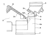
以下、本発明にかかるプレス型について、図面に基づいて説明する。尚、図1は、本発明にかかるプレス型の概略構成を示す斜視図、図2は、図1のプレス型の一部をy方向から見た側面図、図3は、図1のプレス型の一部をx方向から見た側面図である。
図1乃至図3に示すプレス型1は、ワークWを載置して固定する下型2と、この下型2に対して昇降移動により進退するカム3とを備え、それらの間にワークWを挟み込むことによって、ワークWを成形するものである。
Hereinafter, a press die according to the present invention will be described with reference to the drawings. 1 is a perspective view showing a schematic configuration of a press die according to the present invention, FIG. 2 is a side view of a part of the press die of FIG. 1 viewed from the y direction, and FIG. 3 is a press die of FIG. It is the side view which looked at a part from x direction.
A press die 1 shown in FIGS. 1 to 3 includes a
前記下型2は、ワークWの形状に合わせた形状の保持パッド2aを有し、その上にワークWを保持するようになっている。また、下型2において、ワークWの端縁付近には、図3に示すように上向きに下トリム刃4(切断手段)が設けられている。
また、前記カム3は、昇降駆動手段10により所定のカム機構を介して前記ワークWの端縁に対して昇降可能(進退可能)に設けられると共に、図示するようにワークWの長手方向に沿って延設されている。このカム3には、図3に示すように下向きに上トリム刃5(切断手段)が設けられ、前記カム3が下死点まで下降すると、カム3に設けられた押さえ付けパッド3aがワークWを押さえ付けると共に、前記上トリム刃5は前記下型2の下トリム刃4と共働して、ワークWの端縁を切断するようになっている。
The
The
尚、カム3の昇降移動(進退)の軌道をx方向から見ると、図4に示すようになる。即ち、カム3が下降する際には、下型2側(図面左下)に向けて斜めに下降し、上昇する際にはその反対の軌道、即ち下型2とは反対側(図面右上)に向けて斜めに上昇するように構成されている。
また、カム3には、その下方に突出すると共にカム3の進退方向に沿って垂直回転自在なローラ9(押圧手段)が設けられ、このローラ9は、後述するスクラップシュート6の上端側を下方に押さえ付けるようになっている。
Note that the trajectory of the up-and-down movement (advance and retraction) of the
Further, the
前記下型2の下方には、ワークWから切断されて生じたスクラップを受け取り、排出するためのスクラップシュート6が設けられている。このスクラップシュート6は、傾斜面6aを有し、前記ワークWから切断されたスクラップは、前記傾斜面6a上に落下するように配置されている。傾斜面6aに落下したスクラップは、その自重により傾斜面6aを滑動し、型外に排出されるようになっている。
Below the
更にスクラップシュート6の傾斜面6aの下端側には、このスクラップシュート6を回動自在に支持する回転軸7が設けられている。そして、スクラップシュート6の下方には、ピストンシリンダ8(付勢手段)が設けられ、このピストンシリンダ8のピストン8aの一端部がスクラップシュート6の下面(傾斜面6aの下面)に取り付けられている。また、前記ピストン8aは伸長する方向に常時作用しており、それによりピストンシリンダ8はスクラップシュート6を上方に回動させる方向に付勢している。
即ち、スクラップシュート6は、傾斜面6aの下端側の回転軸7を軸として、傾斜面6aの傾斜角が大きくなる方向に回動するよう付勢された状態となされている。
Further, a
That is, the
また、前記傾斜面6aの上端側には、略平面状のガイド面6a1が形成され、このガイド面6a1は、前記のようにピストンシリンダ8により上方に付勢される。このため、ガイド面6a1は、その上方で進退するカム3から下方に突出するローラ9に常に当接するようになっている。
ここで前記カム3は、図4に示したように斜め方向に昇降移動するため、ローラ9は、カム3の昇降移動に伴い前記ガイド面6a1を水平方向(y方向)に転がって移動することになる。
A substantially planar guide surface 6a1 is formed on the upper end side of the
Here, since the
即ち、スクラップシュート6は、傾斜面6aの傾斜角が大きくなる方向に回動するよう付勢される一方、その上端側の前記ガイド面6a1が、カム3と共に昇降するローラ9によって下方に押圧される。
このため、図5に示すように、スクラップシュート6の傾斜面6aは、カム3の昇降移動(進退)に伴って、回転軸7を軸に回動し、その傾斜角がθ1〜θ2の間で変化することになる。
That is, the
For this reason, as shown in FIG. 5, the
また、この構成によれば、スクラップシュート6の下端は位置固定された回転軸7にあり、傾斜角を大きくするために、傾斜面6aの下端が下方に移動するのではなく、回転軸7を軸として傾斜面6aが上方に向けて回動する。このため、高さ方向(z方向)に空間拡大することなく、スクラップを排出するために十分な傾斜角を傾斜面6aに持たせることができる。
Further, according to this configuration, the lower end of the
続いて、前記のように構成されたプレス型1によるワークWの成形工程の一連の動作について説明する。
先ず、図2、図3に示すように下型2の所定位置にワークWを載置する。このとき、カム3は図示するように上死点である。
次いで、昇降駆動手段10によりカム3を下型2側に向け、所定のカム機構を介して斜めに下降開始させる。
尚、ここでカム3のローラ9は、スクラップシュート6のガイド面6a1をy方向に沿って下型2側に転がると共に、下降しながら前記ガイド面6a1を押圧する。これにより、図6、図7に示すようにスクラップシュート6(傾斜面6a)は、回転軸7を軸に傾斜角が小さくなる方向に回動する。
Subsequently, a series of operations in the forming process of the workpiece W by the press die 1 configured as described above will be described.
First, as shown in FIGS. 2 and 3, the workpiece W is placed at a predetermined position of the
Next, the
Here, the
更にカム3の下降が進み、図8、図9に示すように下死点に達すると、カム3は押さえ付けパッド3aによりワークWを押さえ付けると共に、上トリム刃5を下型2の下トリム刃4と共働させてワークWの端縁を切断する。これにより、ワークWが成形される。
ここで、前記上トリム刃5と下トリム刃4とによる切断で生じたスクラップは、前記傾斜面6a上に落下し、傾斜面6aの傾斜(最も小さい傾斜角θ1)によって可能であれば滑動して型外に排出される。
When the
Here, scrap generated by cutting with the
ワークWの成形がなされると、カム3を、下型2側とは反対側に向け、斜めに上昇移動させる。
ここで、カム3のローラ9は、スクラップシュート6のガイド面6a1をy方向に沿って下型2とは反対側に転がると共に、上昇しながら前記ガイド面6a1を押圧する。
これにより、ローラ9に追従してスクラップシュート6のガイド面6a1が上昇し、傾斜面6aの傾斜角が再び徐々に大きくなる。
即ち、図6、図7に示した傾斜の状態を経て、図2、図3に示したようにカム3が上死点まで戻ったときには、傾斜面6aの傾斜角が最も大きい角度θ2となり、傾斜面6aの傾斜が十分に大きく確保され、傾斜面6a上のスクラップを滑動させて型外に排出することができる。
When the workpiece W is formed, the
Here, the
As a result, the guide surface 6a1 of the
That is, when the
以上のように本発明に係るプレス型の実施の形態によれば、傾斜面6aを有するスクラップシュート6は、その下端側が回転軸7を軸として上方に回動するよう付勢されると共に、その上端側のガイド面6a1がカム3のローラ9によって押さえ付けられる。このため、カム3の昇降に伴いスクラップシュート6が回転軸7を軸に回動し、傾斜面6aの傾斜角が可変となされている。
この構成により、カム3が下死点では、スクラップシュート6の傾斜面6aの傾斜角は通常の角度θ1となり、カム3が上死点では、スクラップシュート6の傾斜面6aの傾斜角が最大の角度θ2となる。即ち、通常の傾斜角θ1でスクラップが仮に滑動しない場合であっても、傾斜面6aの傾斜角を角度θ2まで大きくすることができるため、傾斜面6a上のスクラップを滑動させて型外に排出することができる。
また、スクラップシュート6は、位置固定された回転軸7(傾斜面6aの下端)を軸に回動し、それにより傾斜面6aの傾斜角が変化するため、高さ方向(z方向)に空間拡大することなく、スクラップを排出するために十分な傾斜角を傾斜面6aに持たせることができる。
As described above, according to the embodiment of the press die according to the present invention, the
With this configuration, when the
Further, the
尚、前記実施の形態においては、回転軸7を軸として回転自在に設けられたスクラップシュート6に対し、ピストンシリンダ8により上方に回動するよう付勢力を与えるものとしたが、本発明にあっては、その構成に限定されるものではない。
例えば、ピストンシリンダ8ではなく、単にスプリング状の弾性手段によってスクラップシュート6の下面側を上方に押し上げるように構成してもよい。
或いは、スクラップシュート6の下側を上方に押し上げる構成ではなく、スクラップシュート6の上側から上方に引き上げる構成にして、スクラップシュート6を上方に向けて回動するよう付勢してもよい。
In the above embodiment, the scraping
For example, the lower surface side of the
Alternatively, the
1 プレス型
2 下型
2a 保持パッド
3 カム
4 下トリム刃
5 上トリム刃
6 スクラップシュート
6a 傾斜面
6a1 ガイド面
7 回転軸
8 ピストンシリンダ
8a ピストン
9 ローラ
10 昇降駆動手段
W ワーク
DESCRIPTION OF SYMBOLS 1 Press die 2 Lower die
Claims (5)
前記スクラップシュートの下端側に設けられ、該スクラップシュートを回動可能に支持する回転軸と、前記回転軸を軸として前記スクラップシュートが、その傾斜角が大きくなる方向に回動するよう前記スクラップシュートに対し付勢する付勢手段と、前記カムに設けられて該カムと共に昇降し、前記付勢手段により回動付勢された前記スクラップシュートの上端側を下方に押さえ付ける押圧手段とを備え、
前記押圧手段により上端側が押さえ付けられた前記スクラップシュートの傾斜角は、前記カムの下死点と上死点との間において可変となされていることを特徴とするプレス型。 A lower mold for holding a workpiece; a cam provided to be movable back and forth with respect to an edge of the workpiece by moving up and down; a cutting means provided at least on the cam for cutting the edge of the workpiece; A scrap chute provided below the edge of the workpiece, and the cutting means cuts the edge of the workpiece when the cam descends with respect to the edge of the workpiece held by the lower mold. A press die for discharging the cut scrap by the scrap chute,
A rotating shaft provided at a lower end side of the scrap chute and rotatably supporting the scrap chute, and the scrap chute so that the scrap chute rotates in a direction in which an inclination angle increases with the rotating shaft as an axis. An urging means that urges the scrap chute, and a pressing means that is provided on the cam, moves up and down together with the cam, and presses the upper end side of the scrap chute pivoted by the urging means downward,
The press die, wherein an inclination angle of the scrap chute pressed at the upper end side by the pressing means is variable between a bottom dead center and a top dead center of the cam.
前記押圧手段は、前記カムと共に昇降移動する際、前記スクラップシュートの上端側を下方に押圧しながら水平方向に移動することを特徴とする請求項1に記載されたプレス型。 The cam advances and retreats obliquely from above with respect to the edge of the work held by the lower mold,
The press die according to claim 1, wherein the pressing means moves in a horizontal direction while pressing the upper end side of the scrap chute downward when moving up and down together with the cam.
前記ピストンシリンダのピストンの端部が前記スクラップシュートの下面側に取り付けられ、前記ピストンシリンダのピストンが伸長する方向に作用し、前記スクラップシュートを上方に回動させる方向に付勢していることを特徴とする請求項4に記載されたプレス型。 The biasing means is a piston cylinder configured to be extendable and contractible,
The end of the piston of the piston cylinder is attached to the lower surface side of the scrap chute, the piston of the piston cylinder acts in the extending direction, and the scrap chute is biased in the upward direction. The press die according to claim 4, wherein the press die is characterized.
Priority Applications (1)
| Application Number | Priority Date | Filing Date | Title |
|---|---|---|---|
| JP2012086302A JP2013215744A (en) | 2012-04-05 | 2012-04-05 | Press die |
Applications Claiming Priority (1)
| Application Number | Priority Date | Filing Date | Title |
|---|---|---|---|
| JP2012086302A JP2013215744A (en) | 2012-04-05 | 2012-04-05 | Press die |
Publications (1)
| Publication Number | Publication Date |
|---|---|
| JP2013215744A true JP2013215744A (en) | 2013-10-24 |
Family
ID=49588532
Family Applications (1)
| Application Number | Title | Priority Date | Filing Date |
|---|---|---|---|
| JP2012086302A Pending JP2013215744A (en) | 2012-04-05 | 2012-04-05 | Press die |
Country Status (1)
| Country | Link |
|---|---|
| JP (1) | JP2013215744A (en) |
Cited By (3)
| Publication number | Priority date | Publication date | Assignee | Title |
|---|---|---|---|---|
| CN106238606A (en) * | 2016-09-20 | 2016-12-21 | 成都航空职业技术学院 | A kind of automatic remover of the waste material for punching shaving die |
| CN112338005A (en) * | 2020-10-14 | 2021-02-09 | 江苏同力日升机械股份有限公司 | Armrest cover plate bending forming process |
| CN115044734A (en) * | 2022-06-16 | 2022-09-13 | 宝武集团鄂城钢铁有限公司 | Automatic feeding system and chute follow-up control method |
-
2012
- 2012-04-05 JP JP2012086302A patent/JP2013215744A/en active Pending
Cited By (5)
| Publication number | Priority date | Publication date | Assignee | Title |
|---|---|---|---|---|
| CN106238606A (en) * | 2016-09-20 | 2016-12-21 | 成都航空职业技术学院 | A kind of automatic remover of the waste material for punching shaving die |
| CN106238606B (en) * | 2016-09-20 | 2018-05-04 | 成都航空职业技术学院 | A kind of automatic remover of waste material for punching shaving die |
| CN112338005A (en) * | 2020-10-14 | 2021-02-09 | 江苏同力日升机械股份有限公司 | Armrest cover plate bending forming process |
| CN115044734A (en) * | 2022-06-16 | 2022-09-13 | 宝武集团鄂城钢铁有限公司 | Automatic feeding system and chute follow-up control method |
| CN115044734B (en) * | 2022-06-16 | 2024-01-19 | 宝武集团鄂城钢铁有限公司 | Chute follow-up control method |
Similar Documents
| Publication | Publication Date | Title |
|---|---|---|
| KR101454358B1 (en) | Apparatus for Pipe Cutting | |
| JP5398088B2 (en) | Scrap chute and press die equipped with this scrap chute | |
| CN101332568B (en) | Machine tool and method for moving the workpiece part from a support to a discharge position | |
| CN109159212B (en) | Board production line capable of adjusting and adapting to board specifications | |
| CN107186278A (en) | A kind of cutting machine with efficient automatic blanking function | |
| CN109129724B (en) | A highly automated plate processing production line for conveying plates | |
| CN215827792U (en) | Tubular product loading attachment | |
| KR102637322B1 (en) | Roller-type Scrap Remover | |
| JP2013215744A (en) | Press die | |
| CN113770730B (en) | Combined type precise mold frame with two-stage forming function for medical equipment | |
| CN107813596A (en) | Be used for continuous lithography apparatus of sheetmetal | |
| CN217618494U (en) | Panel separation unloader that laser cutting used | |
| CN115319187A (en) | Belt scrap control device and method for blanking line | |
| CN107282747B (en) | Rotate material supporting rack and uncoiling blanking mold | |
| JP6588842B2 (en) | Conveyor device for long objects | |
| KR20150075476A (en) | Apparatus and method for eliminating chip | |
| CN206263347U (en) | A kind of bead cutter with waste material cutting function | |
| KR102291043B1 (en) | Product discharging apparatus for punching and blanking dies | |
| CN110560548B (en) | Ear cap automatic punching and swinging equipment | |
| CN109500234B (en) | Aluminum alloy substrate stamping production line for mechanical hard disk and working method thereof | |
| JP4972214B1 (en) | Vegetable centering and cutting equipment | |
| JP4662180B2 (en) | Press mold structure | |
| CN105312440A (en) | Stamping waste ejection mechanism and stamping die | |
| CN211109790U (en) | Automatic blanking device | |
| CN109226522B (en) | Drawing die material supporting and positioning system and drawing die for inner plate of vehicle trunk |