JP2013223473A - Planting base, method for constructing the same and border part treatment structure of greening area - Google Patents
Planting base, method for constructing the same and border part treatment structure of greening area Download PDFInfo
- Publication number
- JP2013223473A JP2013223473A JP2012108884A JP2012108884A JP2013223473A JP 2013223473 A JP2013223473 A JP 2013223473A JP 2012108884 A JP2012108884 A JP 2012108884A JP 2012108884 A JP2012108884 A JP 2012108884A JP 2013223473 A JP2013223473 A JP 2013223473A
- Authority
- JP
- Japan
- Prior art keywords
- planting base
- water
- water storage
- planting
- recesses
- Prior art date
- Legal status (The legal status is an assumption and is not a legal conclusion. Google has not performed a legal analysis and makes no representation as to the accuracy of the status listed.)
- Granted
Links
Images





Classifications
-
- Y—GENERAL TAGGING OF NEW TECHNOLOGICAL DEVELOPMENTS; GENERAL TAGGING OF CROSS-SECTIONAL TECHNOLOGIES SPANNING OVER SEVERAL SECTIONS OF THE IPC; TECHNICAL SUBJECTS COVERED BY FORMER USPC CROSS-REFERENCE ART COLLECTIONS [XRACs] AND DIGESTS
- Y02—TECHNOLOGIES OR APPLICATIONS FOR MITIGATION OR ADAPTATION AGAINST CLIMATE CHANGE
- Y02A—TECHNOLOGIES FOR ADAPTATION TO CLIMATE CHANGE
- Y02A30/00—Adapting or protecting infrastructure or their operation
- Y02A30/24—Structural elements or technologies for improving thermal insulation
- Y02A30/254—Roof garden systems; Roof coverings with high solar reflectance
-
- Y—GENERAL TAGGING OF NEW TECHNOLOGICAL DEVELOPMENTS; GENERAL TAGGING OF CROSS-SECTIONAL TECHNOLOGIES SPANNING OVER SEVERAL SECTIONS OF THE IPC; TECHNICAL SUBJECTS COVERED BY FORMER USPC CROSS-REFERENCE ART COLLECTIONS [XRACs] AND DIGESTS
- Y02—TECHNOLOGIES OR APPLICATIONS FOR MITIGATION OR ADAPTATION AGAINST CLIMATE CHANGE
- Y02B—CLIMATE CHANGE MITIGATION TECHNOLOGIES RELATED TO BUILDINGS, e.g. HOUSING, HOUSE APPLIANCES OR RELATED END-USER APPLICATIONS
- Y02B80/00—Architectural or constructional elements improving the thermal performance of buildings
- Y02B80/32—Roof garden systems
Landscapes
- Cultivation Of Plants (AREA)
- Cultivation Receptacles Or Flower-Pots, Or Pots For Seedlings (AREA)
Abstract
Description
本発明は、建造物の屋上や屋根、ベランダ等における緑化対策の一貫として使用する植栽基盤及び植栽基盤の施工方法、緑化エリアのボーダー部処理構造に係り、少なくとも底部を有し、該底部上に育成材を載置可能な植栽基盤及び該植栽基盤の施工方法、該植栽基盤により形成された緑化エリアのボーダー部処理構造に関する。 The present invention relates to a planting base used as a part of greening countermeasures on a rooftop, a roof, a veranda, etc. of a building, a construction method of the planting base, and a border part processing structure of a greening area, and has at least a bottom part. The present invention relates to a planting base on which a growing material can be placed, a method for constructing the planting base, and a border portion processing structure of a greening area formed by the planting base.
近年、都市の緑化対策の重要性が認識されつつあり、建造物の屋上、傾斜屋根、ベランダ等においても緑化が図られており、かかる緑化に貢献するものとして、特許文献1に箱状の容器本体の底部に、縦横に延びる上げ底部と、この縦横の上げ底部で区画形成された貯水凹部とが形成され、前記上げ底部には、貯水凹部からあふれ出た水を排水する排水口が形成されており、前記容器本体の底部には、上げ底部よりも上方に突出した筒部が形成されており、この筒部には、容器本体の周壁の排水高さよりも低い位置に排水孔が形成されている緑化容器が開示されており、容器内に水を貯留できる構造となっている。 In recent years, the importance of urban greening countermeasures has been recognized, and greening has been promoted on the rooftops, sloped roofs, verandas, etc. of buildings. The bottom of the main body is formed with a raised bottom extending vertically and horizontally and a water storage recess defined by the vertical and horizontal raised bottom, and a drain outlet for draining water overflowing from the water storage recess is formed on the raised bottom. A cylindrical portion protruding upward from the raised bottom portion is formed at the bottom of the container main body, and a drainage hole is formed in the cylindrical portion at a position lower than the drainage height of the peripheral wall of the container main body. A greening container is disclosed, which has a structure capable of storing water in the container.
しかしながら、上記特許文献1では、貯水凹部相互間を水が行き来できるような通水部が存在しないため、貯水凹部内の水が多くなった場合に容器外へ排水されてしまうという不具合が生じていた。 However, in the above-mentioned
つまり、容器に給水する場合に、容器全体に万遍なく給水する必要があるが、仮に容器の一部分にだけ給水を行った場合は、給水されている箇所にのみ、或いは予め形成されている敷設面の勾配による低勾配側に水分がかたよった状態で溜まり、容器全体に水分が行き渡らなくなり、植物が枯れてしまうという不具合が生じていた。 In other words, when water is supplied to the container, it is necessary to supply water to the entire container. However, if water is supplied only to a part of the container, it is laid only at the place where the water is supplied or pre-formed. There was a problem in that moisture accumulated on the low gradient side due to the surface gradient, the moisture did not spread throughout the entire container, and the plant withered.
また、特許文献1の容器は、射出成形により成形されているため、高価なものとなってしまうという不具合が生じていた。 Moreover, since the container of
また、コスト削減のため、容器自体を大きくする動きがあるが、このような場合、特許文献1の容器は、矩形状に形成されており、1つの容器が入らない空間であるボーダー部の処理が必要になるが、このボーダー部の処理構造に関して何ら開示がなく、決められた広さの緑化エリアしか形成できないという不具合が生じていた。 In addition, there is a movement to enlarge the container itself for cost reduction. In such a case, the container of
本発明は上記課題に鑑みなされたものであり、一部分に給水されたとしても早期に万遍なく植栽基盤全体に水分を行き渡らすことができ、結果的に良好な植物の生育が可能な植栽基盤を提供することを目的とする。 The present invention has been made in view of the above problems, and even if water is supplied to a part of the plant, it is possible to distribute moisture throughout the planting base evenly at an early stage, and as a result, planting that enables good plant growth. The purpose is to provide a planting base.
また、本発明は、安価な植栽基盤を提供することを目的とする。 Another object of the present invention is to provide an inexpensive planting base.
また、本発明は、様々な形状の緑化エリアを簡易に形成可能な緑化エリアのボーダー部処理構造を提供することを目的とする。 It is another object of the present invention to provide a green area border structure that can easily form green areas of various shapes.
本発明の植栽基盤は、少なくとも底部を有し、該底部上に育成材を載置可能な植栽基盤において、該底部は、水分を貯留又は保持可能な複数の貯水又は保水用凹部と、該貯水又は保水用凹部相互を通水可能に連通する複数の連通部を有し、該連通部が複数種類有することを特徴とする。 The planting base of the present invention has at least a bottom part, and in the planting base on which the growing material can be placed on the bottom part, the bottom part has a plurality of water storage or water retaining recessed parts capable of storing or holding moisture, and It has a plurality of communicating parts which communicate with each other so that the water storage or water retaining recesses can pass water, and the communication parts have a plurality of types.
本構成により、給水された水が貯水又は保水用凹部に溜まり、その後、貯水又は保水用凹部に入りきらない水が連通部を通って、他の貯水又は保水用凹部に移動するため、全ての貯水又は保水用凹部に早期に行き渡り、植物が枯れることを防止することができる。 With this configuration, the supplied water is collected in the water storage or water retention recess, and then the water that does not enter the water storage or water retention recess passes through the communication part to another water storage or water retention recess. It is possible to prevent the plant from withering at an early stage in the reservoir for storing water or retaining water.
さらに、本発明の植栽基盤は、前記連通部は、前記貯水又は保水用凹部相互を通水可能に形成された凹溝であり、凹溝の深さが異なることを特徴とする。 Furthermore, the planting base of the present invention is characterized in that the communication part is a groove formed so that the water storage or water retaining recesses can pass through each other, and the depth of the groove is different.
本構成により、例えば、先に深さの深い凹溝を使って、貯水又は保水用凹部相互を行き来し、その後、深さの浅い凹溝を使って、貯水又は保水用凹部相互を行き来できるため、より一層、全体に早期に行き渡らすことができ、植物が枯れることを防止することができる。 With this configuration, for example, it is possible to go back and forth between water storage or water retaining recesses using a deep groove first, and then to go back and forth between water storage or water holding recesses using a shallow groove. Further, it can be spread throughout the entire area at an early stage, and the plant can be prevented from withering.
また、本発明の植栽基盤は、少なくとも底部を有し、該底部上に育成材を載置可能な植栽基盤において、該底部は、水分を貯留又は保持可能な複数の貯水又は保水用凹部を有し、該貯水又は保水用凹部は、相互を通水可能に連通する連通部にて連通されている第1の貯水又は保水用凹部と、第1の貯水又は保水用凹部及び連通部に囲まれて、独立する第2の貯水又は保水用凹部を有することを特徴とする。 In addition, the planting base of the present invention has at least a bottom part, and in the planting base on which the growing material can be placed on the bottom part, the bottom part has a plurality of water storage or water retaining recesses capable of storing or holding moisture. The water storage or water retention recesses are connected to the first water storage or water retention recess and the first water storage or water retention recess and the communication portion communicated with each other so as to allow water to pass therethrough. It has the recessed part for the 2nd water storage or water retention which is enclosed and becomes independent, It is characterized by the above-mentioned.
本構成により、貯水又は保水用凹部の水を全体に行き渡らすための第1の貯水又は保水用凹部と、じっくり貯めるための第2の貯水又は保水用凹部を設けているため、全体に行き渡らすことが出来ると共に、貯水又は保水可能な水分量も確保することができる。 With this configuration, the first water storage or water retention recess for spreading the water in the storage or water retention recess and the second water storage or water retention recess for slowly storing are provided. In addition, the amount of water that can be stored or retained can be secured.
さらに、本発明の植栽基盤は、前記底部から上方に筒状突出部を立設してなることを特徴とする。 Furthermore, the planting base of the present invention is characterized in that a cylindrical projecting portion is erected upward from the bottom portion.
本構成により、育成材を載置する深さを筒状突出部により決定することができ、植栽基盤上に均一に育成材を載置することが可能となると共に、載置作業が容易となる。また、植栽基盤全体の強度アップにつながる。 With this configuration, the depth at which the growing material is placed can be determined by the cylindrical protruding portion, and the growing material can be placed uniformly on the planting base, and the placing work is easy. Become. It also leads to an increase in the strength of the entire planting base.
また、本発明の植栽基盤は、少なくとも底部と、側壁を有する上面開口のトレー形状に形成され、該底部上に育成材を載置可能な植栽基盤において、該底部は、該側壁と略同一高さの筒状突出部と、水分を貯留又は保持可能な複数の貯水又は保水用凹部と、該貯水又は保水用凹部相互を通水可能に連通する連通部を有し、該側壁は、給水管を配設可能な凹部を複数有することを特徴とする植栽基盤。 Further, the planting base of the present invention is formed in a tray shape having at least a bottom part and a top surface opening having a side wall, and the bottom part is substantially the same as the side wall in the planting base on which a growing material can be placed on the bottom part. A cylindrical protrusion having the same height, a plurality of water storage or water retention concave portions capable of storing or retaining moisture, and a communication portion communicating with each other so that the water storage or water retention concave portions can communicate with each other, A planting base comprising a plurality of recesses in which water supply pipes can be disposed.
本構成により、給水に必要な給水管を配設することが容易となると共に、給水管の配設位置を確実に決定することができ、且つ、植栽基盤全体に水分を行き渡らすことが可能となる。 With this configuration, it becomes easy to install the water supply pipes necessary for water supply, the arrangement position of the water supply pipes can be determined reliably, and moisture can be distributed throughout the planting base. It becomes.
さらに、本発明の植栽基盤は、前記側壁には、鉤状連結部が外方に形成されていることを特徴とする。 Furthermore, the planting base | substrate of this invention is characterized by the hook-shaped connection part being formed in the said side wall by the outward.
本構成により、植栽基盤相互の位置決めを確実に行うことが可能となると共に、植栽基盤相互の横ズレを未然に防止することが可能となる。 With this configuration, it becomes possible to reliably position the planting bases, and to prevent lateral displacement between the planting bases.
さらに、本発明の植栽基盤は、前記筒状突出部の回りに、放射状に形成された補強用突状部が形成されていることを特徴とする。 Furthermore, the planting base | substrate of this invention is characterized by the radial-shaped reinforcement protrusion part being formed around the said cylindrical protrusion part.
本構成により、筒状突出部の強度が増し、多少の外力によって変形することが無くなり、より一層確実に育成材を均一に載置することが可能となる。 With this configuration, the strength of the cylindrical protruding portion is increased, and it is not deformed by some external force, and the growing material can be placed even more reliably.
さらに、本発明の植栽基盤は、樹脂の真空成形にて形成されたことを特徴とする。 Further, the planting base of the present invention is formed by resin vacuum forming.
本構成により、安価で軽量な植栽基盤を提供することが可能となる。 This configuration makes it possible to provide an inexpensive and lightweight planting base.
また、本発明の植栽基盤は、少なくとも底部を有し、該底部上に育成材を載置可能な植栽基盤において、該底部は、水分を貯留又は保持可能な複数の貯水又は保水用凹部を有してなり、全体として樹脂の真空成形にて形成されていることを特徴とする植栽基盤。 In addition, the planting base of the present invention has at least a bottom part, and in the planting base on which the growing material can be placed on the bottom part, the bottom part has a plurality of water storage or water retaining recesses capable of storing or holding moisture. A planting base characterized in that it is formed by resin vacuum molding as a whole.
本構成により、貯水又は保水可能な水分量を確保できると共に、安価で軽量な植栽基盤を提供することが可能となる。 With this configuration, it is possible to secure an amount of water that can be stored or retained, and to provide an inexpensive and lightweight planting base.
また、本発明の植栽基盤の施工方法は、敷設面又は植栽基盤の底面裏面に粘着剤又は接着剤を塗布する工程と、植栽基盤を敷設面に敷設する工程と、植栽基盤上に育成材を載置する工程と、育成材に植栽を施す工程を有することを特徴とする。 Moreover, the construction method of the planting base of the present invention includes a step of applying an adhesive or an adhesive to the laying surface or the bottom bottom surface of the planting base, a step of laying the planting base on the laying surface, And a step of placing the growth material on the plant and a step of planting the growth material.
本構成により、より安価に、確実に、早く敷設面に施工することが可能となる。 By this structure, it becomes possible to construct on a laying surface more reliably and quickly.
また、本発明の緑化エリアのボーダー部処理構造は、少なくとも底部に水分を貯留又は保持可能な一定間隔で複数の貯水又は保水用凹部を有し、該底部上に育成材を載置可能な植栽基盤を敷設面に複数敷設して緑化エリアを形成し、該緑化エリアと、縁部との間に存在する残余空間であるボーダー部の処理構造において、該植栽基盤を切断してなる複数の切断片を組み合わせることにより、所定形状の植栽基盤を形成し、該ボーダー部に敷設してなることを特徴とする。 The greening area border processing structure of the present invention has a plurality of water storage or water retaining recesses at regular intervals capable of storing or holding moisture at least at the bottom, and a planting material on which the growth material can be placed on the bottom. A plurality of planting bases are formed by laying a plurality of planting bases on a laying surface to form a greening area, and cutting the planting bases in a processing structure of a border part which is a residual space existing between the greening area and the edge part By combining the cut pieces, a planting base having a predetermined shape is formed and laid on the border portion.
本構成により、簡易に様々な形状の緑化エリアを形成することが可能となると共に、別途部材を使用しなくてもボーダー部の処理を行うことが可能となる。 With this configuration, it is possible to easily form green areas having various shapes, and it is possible to process the border portion without using a separate member.
さらに、本発明の緑化エリアのボーダー部処理構造は、前記植栽基盤は側壁を有するトレー状に形成され、前記切断片を組み合わせることにより、側壁が外周に位置するように前記所定形状の植栽基盤が形成することを特徴とする。 Furthermore, in the bordering structure for a greening area according to the present invention, the planting base is formed in a tray shape having side walls, and the predetermined shape is planted so that the side walls are positioned on the outer periphery by combining the cut pieces. It is characterized by the formation of a base.
本構成により、例えば育成材が粒状のものであっても、側壁が外周に位置するように形成されているため、育成材の流出を未然に防止することができ、確実に植物を生育可能なボーダー部を提供することが可能となる。 With this configuration, for example, even if the growth material is granular, the side wall is formed so as to be located on the outer periphery, so that the outflow of the growth material can be prevented in advance, and the plant can be grown reliably. A border portion can be provided.
さらに、本発明の緑化エリアのボーダー部処理構造は、前記切断片相互を接着することにより、前記所定形状の植栽基盤を形成することを特徴とする。 Furthermore, the bordering structure for a greening area of the present invention is characterized in that the planting base having the predetermined shape is formed by bonding the cut pieces to each other.
本構成により、例えば育成材が粒状のものであっても、切断片相互間からの育成材の流出を未然に防止することができ、確実に植物を生育可能なボーダー部を提供することが可能となる。 With this configuration, for example, even if the growth material is granular, the outflow of the growth material from between the cut pieces can be prevented in advance, and it is possible to provide a border portion that can reliably grow plants. It becomes.
さらに、本発明の緑化エリアのボーダー部処理構造は、前記切断片は、少なくとも3片有し、略中間に位置する少なくとも1つの切断片の上に、少なくとも2つの切断片を前記貯水又は保水用凹部を合わせた状態で載置する、或いは少なくとも2つの切断片の上に、略中間に位置する少なくとも1つの切断片を載置することにより前記所定形状の植栽基盤を形成することを特徴とする。 Furthermore, in the bordering structure for a greening area according to the present invention, the cut piece has at least three pieces, and at least two cut pieces are used for storing or retaining water on at least one cut piece located substantially in the middle. It is characterized by forming the planting base of the predetermined shape by placing the concave portions together or placing at least one cut piece located substantially in the middle on at least two cut pieces. To do.
本構成により、例えば育成材が粒状のものであっても、切断片相互間からの育成材の流出を未然に防止することができ、確実に植物を生育可能なボーダー部を提供することが可能となると共に、ボーダー部における植栽基盤の強度が増し、安定した植栽基盤としての役割を果たすことができる。 With this configuration, for example, even if the growth material is granular, the outflow of the growth material from between the cut pieces can be prevented in advance, and it is possible to provide a border portion that can reliably grow plants. At the same time, the strength of the planting base in the border portion increases and can serve as a stable planting base.
本発明の植栽基盤は、貯水又は保水用凹部相互間を連通部で連通しているため、水分を植栽基盤全体に行き渡らすことが可能となり、結果的に植物に対して十分に水分を与えることができ、良好に生育させることが可能となる。 Since the planting base of the present invention communicates between the reservoirs or the water retaining recesses through the communication part, it becomes possible to spread the moisture throughout the planting base, and as a result, the plant has sufficient moisture. It can be given and can grow well.
また、本発明の植栽基盤は、真空成形にて形成した場合、安価で製造することが可能となる。 Moreover, when the planting base of the present invention is formed by vacuum forming, it can be manufactured at low cost.
また、本発明の植栽基盤の施工方法は、粘着剤又は接着剤で敷設面に貼り付けるだけで良いため、安価に、且つ確実に、早く敷設面に施工することが可能となる。 Moreover, since the construction method of the planting base | substrate of this invention should just affix on a laying surface with an adhesive or an adhesive agent, it becomes possible to construct on a laying surface quickly and reliably cheaply.
また、本発明の緑化エリアのボーダー部処理構造は、様々な形状の緑化エリアを簡易に形成可能となり、且つボーダー部においても良好に植物を生育することが可能となる。 The greening area border structure according to the present invention can easily form green areas of various shapes, and can grow plants well in the border area.
以下、本発明の植栽基盤及び植栽基盤の施工方法について、図面に沿って説明するが、本発明は下記実施例に限定されるものではない。 Hereinafter, although the planting base | substrate of this invention and the construction method of a planting base | substrate are demonstrated along drawing, this invention is not limited to the following Example.
<第1実施例>
図1〜図3は本発明の第1実施例の植栽基盤を示し、図1は植栽基盤を示す図であり、図2は植栽基盤を敷設面に敷設した状態を示す図であり、図3は植栽基盤の水の移動を示す説明図である。<First embodiment>
1 to 3 show the planting base of the first embodiment of the present invention, FIG. 1 is a view showing the planting base, and FIG. 2 is a view showing a state where the planting base is laid on the laying surface. FIG. 3 is an explanatory view showing the movement of water on the planting base.
図1に示すように、第1実施例の植栽基盤100は平面視略正方形の平板状からなる底部101と、この底部101に縦横4個ずつ均等に合計16個が配列され、底部101より下方に、且つ平面視正方形状にへこんでいる貯水又は保水用凹部102が形成されており、この貯水又は保水用凹部102相互を凹溝からなる連通部103で連通している。尚、植栽基盤100の大きさは、300mm×300mm、350mm×350mm、500mm×500mm、600mm×600mm、1000mm×1000mm等適宜であるが、大きければ大きいほど、施工性が向上し、コストダウンとなる。 As shown in FIG. 1, the
この連通部103は、図面上、横方向に隣り合う貯水又は保水用凹部102相互を連通する連通部103aと、図面上、縦方向に隣り合う貯水又は保水用凹部102相互を連通する連通部103bとで、溝の深さが異なっており、図示横方向の溝が深くなっている深溝連通部103aと、図示縦方向の深さが浅くなっている浅溝連通部103bで構成されている。 The communication portion 103 includes a
また、縦横に隣り合う4個の貯水又は保水用凹部102及びこれらを連通する連通部103a、103bに囲まれた底部101に、8方向に放射状に配置され、且つ底部101を上下に貫通する17個の孔104が穿設されており、余剰水が排水されると共に、通気も可能な構造となっており、全体として真空成形にて形成されている。 Also, four water storage or water retention recesses 102 that are adjacent in the vertical and horizontal directions and a
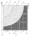
以上からなる植栽基盤100を図2に示すように、敷設面105に隙間なく敷き詰め、その上に、育成材106を載置し、その上に植物107を施すことにより、緑化エリア108が形成されることとなる。尚、緑化エリア108が外周には縁部である縁石などの見切り材109を設ける等適宜であり、全体として美観に優れた緑化エリア108が形成される。尚、敷設面105と植栽基盤100の間には粘着剤又は接着剤を塗布していることから、植栽基盤100の耐負圧力が向上することとなる。この粘着剤又は接着剤の塗布は全面に行っても良く、又は部分的に塗布しても良く、更には塗布しなくても良い。尚、植栽基盤100の撤去或いは移設等を考慮すると、粘着剤の方が良い。上記見切り材109としてはどのようなものであっても良く、石材、木材、発泡材、樹脂成型材、鋼板の折り曲げ材、押出し成型材、ゴム等適宜であり、見切り材109は植栽基盤100に固定、敷設面105に固定、非固定等適宜であり、且つ固定方法も接着固定、粘着固定、ビス固定、アンカー固定等適宜であり、緑化エリア108と非緑化エリアを仕切ることができればどのような構造、材質であっても良い。 As shown in FIG. 2, the
尚、図3に示すように、第1実施例の植栽基盤100は、例えば、図面上で上が高勾配で下が低勾配の場合、「0」の貯水又は保水用凹部102に給水などで水が供給され、「0」部が満水になると、まず横方向の連通部103aの溝が深い箇所を通って「1」更には「2」へと水が流れると共に貯水又は保水されていく。その後、横方向が全て満水となると、次に連通部103bの溝が浅い縦方向で且つ勾配に沿って水が流れ、「3」、「4」更には「5」へと水が流れると共に貯水又は保水されていくこととなり、確実に植栽基盤100全体に水分が行き渡ることとなる。尚、給水や降雨などで全ての貯水又は保水用凹部102が満水となると、孔104或いは植栽基盤100相互間から排水されることは言うまでもない。 As shown in FIG. 3, the
尚、本発明で載置される育成材106としては、例えばパーライト、バーミキュウライト、ピートモス、バーク堆肥、チャフコン、木質腐朽有機物、ゼオライト、木炭、下水或いは浄水場から発生する汚泥、或いは汚泥の焼却灰、火山灰、竹炭等とすることができ、又、これらの内の数種類を選定し、これらを保水性、排水性を良好にするためにバランス良く配合したもの、若しくはこれらの数種類を層状に設けたもの、或いはこれらの単体で若しくは配合して固化しブロック状にした軽量育成材や、スポンジ、ロックウール、ウレタン、ヤシガラ等の繊維材等を結合してなるマット状の軽量育成材等としてもよい。かかる通気性良好な軽量育成材を育成材として採用することにより、植物の根が傷むことを防止でき、又、これらの軽量育成材による荷重は従来の客土の約1/3程度であることから、敷設面105への荷重負荷を軽減することができる。尚、ブロック状、或いはマット状の育成材を使用すると施工性が向上すると共に飛散を防止することができる。また、粒状の育成材を使用するとコスト低減効果を発揮することができる。 The growing
また、育成材106に施される植物107は芝等の地被植物、草花、木、セダム等の多肉植物、蔓性植物、苔等適宜であり、これらの組み合わせであっても良く、更には、これらの植物の種を播種して施す、或いはこれらの植物をマット状にして育成材上に載置する、或いはこれらの植物をポット状として育成材に植栽を施す等適宜である。尚、ポット状の植物を施す場合は、育成材106として、比重が重いものを使用する或いは上層だけ比重の重いものを使用すると好適であり、育成材106の飛散防止効果が発揮できる。 Further, the
また、敷設面105とは、植栽基盤100が設置可能な箇所であれば全て含まれ、例えば建物の屋上に直接、或いは防水シート上、或いは防水シート上に更に設けられた耐根シート上等適宜であり、更には山部や谷部が連続して設けられる折板屋根等の平面である必要もなく、植栽基盤100を設置する箇所を意味している。 Further, the laying
本実施例の植栽基盤100を使用することにより、例えば給水などを施す場合、給水などにより供給された水分が植栽基盤100全体に行き渡るため、結果的に植物107に対して十分に水分を与えることができ、良好に生育させることが可能となる。しかし、セダムや苔等、植物107の種類によっては、給水を施す必要がなく、自然降雨で植物を生育することができる。 By using the
また、粘着剤又は接着剤で敷設面105に貼り付けるだけで良いため、安価に、且つ確実に、早く敷設面105に施工することが可能となる。 Moreover, since it is only necessary to affix on the laying
また、底部101の裏面が凹凸形状となっているため、敷設面105に水分がたまることがなく、良好な排水が施される。 Moreover, since the back surface of the
また、孔104の敷設面と離れているため、排水が良好に行われるだけでなく、植物107の根に対して新鮮な空気を送ることが可能であるため、良好な植物107の生育が可能となっている。 Moreover, since it is away from the laying surface of the
<第2実施例>
次に、本発明の第2実施例について、上記第1実施例と異なる箇所の詳細を説明する。図4〜図6は本発明の第2実施例の植栽基盤を示し、図4は植栽基盤を示す図であり、図5は植栽基盤を敷設面に敷設した状態を示す図であり、図6は植栽基盤と給水設備との関係を示す図である。<Second embodiment>
Next, the second embodiment of the present invention will be described in detail with respect to the differences from the first embodiment. FIGS. 4-6 shows the planting base | substrate of 2nd Example of this invention, FIG. 4 is a figure which shows a planting base | substrate, FIG. 5 is a figure which shows the state which laid the planting base | substrate on the laying surface. FIG. 6 is a diagram showing the relationship between the planting base and the water supply facility.
図4に示すように、第2実施例の植栽基盤200は平面視略正方形の平板状からなる底部201と、この底部201に縦横10個ずつ均等に合計100個が配列され、底部201より下方に、且つ平面視略八角形状にへこんでいる貯水又は保水用凹部202aが形成されており、この貯水又は保水用凹部202a相互を凹溝からなる連通部203で連通している。この貯水又は保水用凹部202aが本願発明の第1の貯水又は保水用凹部202aを意味しており、相互に連通部203a、203bで連通された状態となっている。 As shown in FIG. 4, the
この連通部203は、図面上、横方向に隣り合う貯水又は保水用凹部202a相互を連通する連通部203bと、図面上、縦方向に隣り合う貯水又は保水用凹部202a相互を連通する連通部203aとで、溝の深さが異なっており、図示横方向の溝が深くなっている深溝連通部203aと、図示縦方向の溝が浅くなっている浅溝連通部203bで構成されている。 The communication portion 203 includes a
また、縦横に隣り合う4個の貯水又は保水用凹部202a及びこれらを連通する連通部203a、203bに囲まれた底部201のうちの一部に、平面視略円形に下方にへこんでなる貯水又は保水用凹部202bが形成されており、且つこの貯水又は保水用凹部202bの略中心部に上方に前記底部201と略同一高さまで突出した面状部211が形成され、この面状部211に上下に貫通する孔204が穿設されており、余剰水が排水されると共に通気が可能な構造となっている。更に、前記面状部211の周りに形成された貯水又は保水用凹部202bを跨ぐように上方にトンネル状に突出した経路部212が四方に形成されており、孔204から排出された余剰水がどの方向へも流れ出ることが可能で、且つ通気も可能な構成となっている。尚、孔204は植栽基盤200の辺中央相互を結ぶ中心線上に存在する面状部211には、4つ穿設され、他の面状部には5つ穿設されている。 In addition, the water storage or recess that is recessed in a substantially circular shape in a plan view in a part of the
また、縦横に隣り合う4個の貯水又は保水用凹部202a及びこれらを連通する連通部203a、203bに囲まれた底部のうちの前記面状部211が形成されていない箇所には、同様に貯水又は保水用凹部202bが形成され、且つこの貯水又は保水用凹部202bの略中心部に前記面状部211よりも上方で、且つ後述する側壁215と略同一高さまで突出している筒状突出部213が形成されており、この筒状突出部213の周りには補強用突状部であるリブ214が四方に放射状に形成されている。これらの貯水又は保水用凹部202bが本願発明の第2貯水又は保水用凹部202bを意味しており、独立して存在している。また、筒状突出部213にリブ214を設けているため、ある程度の上方から、或いは側方からの力による変形、破損を防止することが可能になっている。 In addition, in the place where the
また、底部201の周縁には、上方に側壁215が立設しており、且つ側壁215の上端部を外方に屈曲延設してなる鉤状連結部216で形成されている。この鉤状連結部216は、隣り合う2側壁が幅広及び高さの高い幅広連結部216aとし、他の隣り合う2側壁が幅狭及び高さの低い幅狭連結部216bとして形成され、この幅狭連結部216bに他の植栽基盤の幅広連結部216aを被せることにより、連結が可能な構成となっている。また、角部分はこれら鉤状連結部216が干渉しないように切断部217が形成されており、良好な連結作業を行うことが可能となっている。 In addition, a
また、側壁215及び鉤状連結部216の上面には、後述する給水管219を配設可能な凹部218が1つの側壁215に5箇所形成されており、好きな箇所に給水管219を配設可能な構成となっている。 In addition, on the upper surfaces of the
以上からなる植栽基盤200を図5に示すように、敷設面205に敷き詰める際に、幅狭連結部216a上に幅広連結部216bを被せるように連結させながら敷設し、その上に、育成材206を載置すると共に、前記凹部218に給水管219を配設し、更には育成材206に植物207を施すことにより、緑化エリア208が形成されることとなる。尚、上記第1実施例同様に、縁部である縁石などの見切り材209及び粘着剤又は接着剤の塗布を行う。尚、後述するように給水管219を配設する際に、給水管219への水の供給、停止を行う電磁弁221を収納するための電磁弁収納部材220が設けられており、見切り材209の一部の役割を果たしている。 As shown in FIG. 5, when the
前記育成材206を載置する際に、育成材206の厚さを必要としない植物207の場合は、植栽基盤200から立設している筒状突出部213の上端を育成材206の厚さとして、均一に載置することができる。つまり、筒状突出部213の高さが育成材206の最低の厚さの場合の目安としての役割を果たしている。また、育成材206の水平方向への移動も未然に防止している。 In the case of a
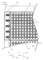
また、前記給水管219の配設方法は、図6に示すように電磁弁収納部材220に収納された5つの電磁弁221から給水管219が出ており、1個の植栽基盤200の1辺に設けられた5つの凹部218から植栽基盤200内に給水管219が入り込んでおり、各給水管219は屈曲しながら、且つそれぞれの凹部218を利用して各植栽基盤200に行き渡り、給水を可能にしている。尚、給水管219としては多孔質パイプ、浸み出しパイプ、ドリップパイプ等適宜である。 Further, as shown in FIG. 6, the
本実施例の植栽基盤200を使用することにより、第1実施例の効果及び実施例の説明中に説明した効果を奏すると共に、電磁弁収納部材220を見切り材209の一部として使用するため、別途電磁弁221を収納するための部材を設ける必要がなく、美観に優れた緑化エリア208を形成することが可能と共に、コストダウン効果も得られる。 By using the
また、給水管219を緑化エリア208内で引きまわしているため、別途緑化エリア208外に給水管219を収納するための部材を設ける必要が無く、美観に優れた緑化エリア208を形成することが可能と共に、コストダウン効果も得られる。 Further, since the
また、給水管219は植栽基盤200の凹部218を通って、植栽基盤200内に入り込んでいるため、給水管219自体が安定して配設することが可能であると共に、移動する虞が無く、確実に給水を行うことができる。 In addition, since the
また、筒状突出部213の下端に貯水又は保水用凹部202bが存在するため、植物207の根が筒状突出部213に沿って下方へ向かい、水分が存在する貯水又は保水用凹部202bに到達するため、確実に植物207へ水分が供給され、良好な生育が可能と共に、根絡みも良好で、植物207の飛散防止効果も得られる。また、筒状突出部213の下端が敷設面205に当接していることから、強度向上が図られている。 In addition, since the water storage or
また、連通部203で連通されている第1の貯水又は保水用凹部202aと独立して存在している第2の貯水又は保水用凹部203bが存在するため、十分な貯水又は保水量を確保できると共に、第1の貯水又は保水用凹部202aに貯水又は保水されている水分は連通部203を利用して早期に植栽基盤200全体に行き渡らすと共に、第2の貯水又は保水用凹部202bに貯水又は保水されている水分は育成材206の毛細管現象を利用して徐々に植栽基盤200全体に行き渡らすことができ、良好な植物207の生育が可能となっている。また、貯水又は保水用凹部203を複数有することから、敷設面205に当接する面が増え、粘着或いは接着面が増えて敷設面205への固定強度が向上する。 Moreover, since the 2nd water storage or the water retention recessed
また、側壁215が存在することから、育成材206が粒状であっても対応することができ、育成材206が流出することを防止可能となっており、また、植栽基盤200を敷設面205に敷設する前に、予め植栽基盤200に育成材206を載置充填して、敷設面205に敷設する、或いは植栽基盤200に育成材206を載置充填すると共に植物207を施しておいて、敷設面205に敷設する等、様々な対応が可能となっているが、植栽基盤200の強度等によっては、育成材206の載置充填及び植物207を施す工程は敷設面205への敷設後の方が良い場合もある。 Moreover, since the
また、鉤状連結部216により植栽基盤200相互を連結しているため、耐負圧に対して強くなると共に、植栽基盤200の移動、植栽基盤200相互の隙間等の発生を防止することが可能となっており、確実に、簡単に敷設面205に植栽基盤200を複数敷設することが可能となっており、植栽基盤200相互の位置ずれも未然に防止することができる。 In addition, since the planting bases 200 are connected to each other by the hook-shaped connecting
<実施例の変形例等>
以上、本発明の実施例について説明したが、本発明は要旨の範囲内において、拡張及び変形が可能であり、各発明や実施例の構成の他に、これらの部分的な構成を本明細書開示の他の構成に変更して特定したもの、或いはこれらの構成に本明細書開示の他の構成を付加して特定したもの、或いはこれらの部分的な構成を部分的な作用構成が得られる限度で削除して特定した上位概念化したものも含まれ、例えば下記のような変形例も包含される。<Modifications of Examples>
Although the embodiments of the present invention have been described above, the present invention can be expanded and modified within the scope of the gist, and in addition to the configurations of the inventions and embodiments, these partial configurations are described in this specification. What is specified by changing to other configurations disclosed, or what is specified by adding other configurations disclosed in this specification to these configurations, or a partial operational configuration of these partial configurations can be obtained Also included are high-level concepts that are identified by being deleted at the limit. For example, the following modifications are also included.
上記植栽基盤は、平面視正方形で説明したが、多角形、円形、楕円形、直線と曲線を組み合わせた外形形状等適宜であり、正多角形ではなく、長方形、菱形等適宜であり、且つ植栽基盤の各種構成の個数、形状、大きさ(寸法)、位置などは上記実施例に限定さるものではなく、また、各種構成を植栽基盤に対して一体に成形する或いは別体で成形して組み合わせる構成であっても良い。特に、第2実施例の筒状突出部は、育成材の載置厚さによって、様々選定できるようにしても良い。また、各種構成に関して、本発明の要旨の範囲内において、不要なものは削除しても良い。更に、上記実施例では連通部を凹溝とし、深さを異ならせているが、幅を異ならせる、数を異ならせる、これらの組み合わせで異ならせる等適宜であり、必ずしも異ならせる必要もなく、更には無くても良い。 The above planting base has been described as a square in plan view, but it is appropriate as a polygon, a circle, an ellipse, an outer shape combining straight lines and curves, etc., not a regular polygon, but a rectangle, rhombus, etc., and The number, shape, size (dimension), position, etc. of the various configurations of the planting base are not limited to the above-mentioned embodiments, and the various configurations are molded integrally with the planting base or formed separately. The configuration may be combined. In particular, the cylindrical protruding portion of the second embodiment may be variously selected depending on the mounting thickness of the growing material. Further, regarding various configurations, unnecessary ones may be deleted within the scope of the gist of the present invention. Furthermore, in the above embodiment, the communicating portion is a concave groove, and the depth is different, but the width is different, the number is different, and the combination is appropriate, and it is not necessary to make it different. Furthermore, it is not necessary.
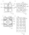
例えば、図7(a)に示すように、植栽基盤300を底部301に平面視円形の4個の貯水又は保水用凹部302を4個形成し、図面視横に並ぶ貯水又は保水用凹部302相互を幅の広い凹溝の広溝連通部303aで連通し、図面視縦に並ぶ貯水又は保水用凹部302相互を幅の狭い凹溝の狭溝連通部303bで連通すると共に、底部301の適宜箇所にスリット状の孔304を複数形成する構成であっても良く、本実施例の植栽基盤を使用することにより、育成材が粒径の場合であって落下することなく、確実に排水或いは通気が可能となる。 For example, as shown in FIG. 7A, the
また、図7(b)に示すように、植栽基盤400を底部401に平面視略円形で相互に連通部403a、403bで連通してなる貯水又は保水用凹部402aを4個形成し、図面視横に並ぶ貯水又は保水用凹部402a相互を幅の広い凹溝の広溝連通部403aで連通し、図面視縦に並ぶ貯水又は保水用凹部402a相互を幅の狭い凹溝の狭溝連通部403bで連通すると共に、貯水又は保水用凹部402aと連通部403a、403bで囲まれた底部401に独立した貯水又は保水用凹部402bを形成すると共に、貯水又は保水用凹部402aには、平面視四角形状の筒状突出部413を形成してなる構成であっても良く、本実施例の植栽基盤を使用することにより、植栽基盤の周りから先に水分が行き渡らせることができると共に、孔を有さないため、別途孔開け加工が不要となり、より安価に製造することが可能となる。尚、余剰水の排水或いは通気は、植栽基盤400相互間の隙間で行う構成となっている。 Moreover, as shown in FIG.7 (b), the four
また、図7(c)に示すように、植栽基盤500を底部501の四隅部分に平面視小さく、更に図面視横方向で向かい合う辺の略中央部近傍に平面視大きく、凹溝の全てが同じ深さ及び幅の連通部503で連通された平面視四角形の貯水又は保水用凹部502aを合計6個形成し、他の底面501には丸状の孔504を複数形成し、周辺には連結部などが存在しない側壁515を立設し、且つ図面視縦方向で向かい合う2辺の側壁515には給水管を保持可能な凹部518が形成されており、更に、底部501に平面視円形で相互に独立して形成された貯水又は保水用凹部502bが形成され、この貯水又は保水用凹部502bからは筒状突出部513が突出形成されている構成であっても良く、本実施例の植栽基盤を使用することにより、育成材を載置収納した状態、或いは育成材を載置収納し植物を施した状態で敷設面へもって行くことができ、施工性が向上すると共に、水分が行き渡りにくい給水管から慣れた位置に貯水又は保水用凹部502a、502bが存在することから、植栽基盤全体に水分を行き渡らすことが可能となる。 Further, as shown in FIG. 7 (c), the
また、図7(d)に示すように、平面視長方形の植栽基盤600の底部601に図面視横に3個、縦に4個に並んで合計12個の平面視四角形のそれぞれ独立した貯水又は保水用凹部602を形成し、これを真空成形で形成する構成であっても良く、本実施例の植栽基盤を使用することにより、更に安価な植栽基盤を製造することが可能となる。 Moreover, as shown in FIG.7 (d), in the
また、給水管の配設方法は適宜であり、従来通り、緑化エリア外に給水管を配設し、必要箇所から緑化エリア内に給水管を入り込ませる構成であっても良く、また、電磁弁収納部材もなくても良い。更には、図8に示すように水源近くに電磁弁を並べて、必要系統数を緑化エリアまで配管用のカバー225内に収納した状態で配設し、それぞれの配管を緑化エリア内に導く構成であっても良い。 In addition, the method of arranging the water supply pipe is appropriate, and as usual, the water supply pipe may be arranged outside the greening area, and the water supply pipe may be inserted into the greening area from a necessary location. There may be no storage member. Furthermore, as shown in FIG. 8, solenoid valves are arranged near the water source, and the necessary number of systems are arranged in a state where they are housed in the
また、図9に示すように、例えば第2実施例の場合、植栽基盤200に入り込んだ給水管219のあばれを防ぐための給水管保持部材222を筒状突出部213に設けても良く、安定した給水管219の配設が可能となる。この給水管保持部材222は、図に示すように給水管219を保持する細長状の基部223と、基部223の長手方向両端に下方に屈曲し、植栽基盤200の筒状突出部213に係合する係合部224を有し、筒状突出部213に係合部224を係合させる(突き刺す)ことにより、基部223の下端で給水管219を保持する構成となっており、確実に、安定して給水管219を保持することが可能となっている。 In addition, as shown in FIG. 9, for example, in the case of the second embodiment, a water supply
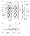
また、本発明の緑化エリアのボーダー部処理構造として、例えば第2実施例の植栽基盤200を使用した場合、例えば図10(a)の切断箇所S1、S2にて切断し、図10(b)に示すように外側の2つの外側切断片230a及び中央の1つの中央切断片230bが形成される。尚、三分割の中央切断片230bに関しては、後述する外側切断片230aの被せ時に邪魔となる側壁等が不要なため、切断箇所S2を切断することにより側壁を切断する。 Moreover, when using the planting base |
以上からなる中央切断片230bに覆い被せるように重ね合わせ、且つ1対の外側切断片230aの切断箇所か略接するように配置することにより、図10(c)に示すように貯水又は保水用凹部、連通部、筒状突出部が位置決め効果を発揮して図面上横幅の小さい植栽基盤200aが作られる。この植栽基盤200aをボーダー部に設置しても良い。 A water storage or water retaining recess as shown in FIG. 10 (c) by overlapping the
更に、図面上高さを小さくしたい場合は、図10(d)に示すような切断箇所にて切断して、図10(e)に示すように新たな切断片230a及び230bを形成し、これらを組み合わせることにより、図10(f)に示すように幅及び高さの小さい植栽基盤200bが形成され、この植栽基盤200bをボーダー部に設置しても良い。 Further, when it is desired to reduce the height in the drawing, cutting is performed at a cutting portion as shown in FIG. 10 (d) to form
以上のように、様々な幅及び高さの植栽基盤を作ることが可能であるため、正規の植栽基盤200と縁部である見切り材、建物の壁、パラペット等との間に残余空間が存在したとしても、簡易に対応することが可能となり、様々な緑化エリアを形成することが可能となる。 As described above, since it is possible to make planting bases of various widths and heights, the remaining space between the
尚、上記緑化エリアのボーダー部処理構造は、必要に応じて外側切断片230a相互の接合部に接着テープ等で接着しても良く、より強固なボーダー部の植栽基盤を形成することが出来ると共に、より確実に育成材の流出を防止することができる。 In addition, the border part processing structure of the said greening area may adhere | attach to the junction part of the outer side cut
以上、上記構成の緑化エリアのボーダー部処理構造を採用することにより、粒状の育成材は、側壁の突き合わせ部分にて流出を防止すると共に、貯水又は保水用凹部は突き合わせ部分においても、下に存在する中央切断片230aにより、確実に機能を維持することが可能となる。 As described above, by adopting the border processing structure of the greening area having the above-described structure, the granular growth material prevents the outflow at the abutting portion of the side wall, and the recessed portion for water storage or water retention also exists under the abutting portion. The function can be reliably maintained by the
尚、緑化エリアのボーダー部処理構造について説明したが、必ずしも外側切断片230aの切断箇所相互が略接する必要はなく、離れていても良い。また、逆に外側切断片230aの切断箇所相互が接しており、接着テープなどで接着することにより、中央切断片230bを使用しない構成であっても良い。また、中央切断片230bを外側切断片230a上に被せるように重ねる構成であっても良く、植栽基盤底面と敷設面に段差が生じることがなく、好適である。また、分割片は必ずしも3つである必要はなく、組み合わせる分割片は2つ以上であれば、全て含まれる。 In addition, although the border part processing structure of the greening area was demonstrated, the cut | disconnection location of the outer side cut
また、植栽基盤自体を真空成形にて形成すると安価で好適であるが、必ずしも真空成形で行う必要はなく、射出成形等であっても良く、また、材質も樹脂である必要なく、鋼板、石材、木材、発泡材等適宜であり、例えば鋼板なら絞り加工、曲げ加工や溶接、組立等により成形する等適宜である。 Moreover, although it is cheap and suitable to form the planting base itself by vacuum forming, it is not always necessary to perform by vacuum forming, it may be injection molding or the like, and the material does not have to be a resin, Stone, wood, foam, etc. are appropriate. For example, a steel plate is appropriately formed by drawing, bending, welding, assembly, or the like.
尚、樹脂などの射出成型の場合は、例えば連通部を凹溝にする必要はなく、例えば貯水又は保水用凹部の側部相互を連通する孔であっても良く、孔の高さ、径、形状、数、これらの組み合わせを異ならせる等適宜であり、必ずしも異ならせる必要もない。更に、連通部を不織布等毛細管現象が起こる部材を貯水又は保水用凹部相互間に配置する構成であっても良く、これら毛細管現象が起こる部材を変更する、或いは部材の幅、厚さを変更する等適宜である。 In the case of injection molding of resin or the like, for example, the communication portion does not need to be a concave groove, and may be, for example, a hole communicating with the side portions of the concave portion for water storage or water retention. The shape, number, and combinations thereof are appropriately changed, and are not necessarily different. Further, the communication part may be configured such that a member that causes capillary action such as a nonwoven fabric is disposed between the recessed portions for water storage or water retention, and the member that causes the capillary action is changed, or the width and thickness of the member are changed. Etc. as appropriate.
また、貯水又は保水用凹部は、貯水又は保水可能であれば全て含まれ、貯水の場合は、例えば底部上に仕切板を設けてその上に育成材を充填する、或いは育成材をマット或いはブロック状として貯水又は保水用凹部全体に侵入しないような構造とし、貯水又は保水用凹部に水分を貯留可能な構造であれば良く、また、保水の場合は、植栽基盤自体に粒状の育成材を充填することにより、保水する或いは、育成材とは異なる保水材を貯水又は保水用凹部に充填或いは設ける構成とし、貯水又は保水用凹部に水分を保持可能な構造であれば良い。 In addition, the water storage or water retaining recesses are all included if water storage or water retention is possible. In the case of water storage, for example, a partition plate is provided on the bottom and the growth material is filled thereon, or the growth material is matted or blocked. As long as it has a structure that does not penetrate into the entire recess for storing or retaining water as long as it has a structure that can store water in the recess for storing or retaining water, and in the case of retaining the water, a granular growth material is applied to the planting base itself. Any structure may be used as long as it can retain water by filling, or have a structure in which a water retention material different from the growth material is filled or provided in the water storage or water retention recess, and can retain moisture in the water storage or water retention recess.
また、第2実施例の鉤状連結部は必須条件ではなく、無くても良い。更に、鉤状である必要はなく、様々な連結構造も含まれる。 Further, the hook-shaped connecting portion of the second embodiment is not an essential condition and may be omitted. Furthermore, it does not need to be hook-shaped and includes various connecting structures.
本発明の植栽基盤は、建築物の屋上、屋根、ベランダ等の人工地盤上に緑化エリアを形成しうる植栽基盤に利用することができる。 The planting base of the present invention can be used as a planting base that can form a greening area on an artificial ground such as a rooftop, a roof, or a veranda of a building.
100、200、300、400、500、600・・・植栽基盤
101、201、301、401、501、601・・・底部
102、202、302、402、502、602・・・貯水又は保水用凹部
103、203、303、403、503・・・連通部
104、204、304、504・・・孔
105、205・・・敷設面
106、206・・・育成材
107、207・・・植物
108、208・・・緑化エリア
109、209・・・見切り材
211・・・面状部
212・・・経路部
213、413、513・・・筒状突出部
214・・・補強用突状部
215、515・・・側壁
216・・・鉤状連結部
217・・・切断部
218、518・・・凹部
219・・・給水管
220・・・電磁弁収納部材
221・・・電磁弁
222・・・給水管保持部材
223・・・基部
224・・・係合部
225・・・配管用カバー
230・・・切断片
S・・・切断線100, 200, 300, 400, 500, 600 ... planting
Claims (14)
該底部は、水分を貯留又は保持可能な複数の貯水又は保水用凹部と、
該貯水又は保水用凹部相互を通水可能に連通する複数の連通部を有し、
該連通部が複数種類有することを特徴とする植栽基盤。In a planting base having at least a bottom and capable of placing a growing material on the bottom,
The bottom portion includes a plurality of water storage or water retention recesses capable of storing or holding moisture,
A plurality of communicating portions communicating with each other so that the water storage or water retaining recesses can pass through each other;
A planting base characterized in that the communication part has a plurality of types.
該底部は、水分を貯留又は保持可能な複数の貯水又は保水用凹部を有し、
該貯水又は保水用凹部は、相互を通水可能に連通する連通部にて連通されている第1の貯水又は保水用凹部と、
第1の貯水又は保水用凹部及び連通部に囲まれて、独立する第2の貯水又は保水用凹部を有することを特徴とする植栽基盤。In a planting base having at least a bottom and capable of placing a growing material on the bottom,
The bottom portion has a plurality of water storage or water retention recesses capable of storing or holding moisture,
The water storage or water retention recess is a first water storage or water retention recess communicated by a communication portion that allows water to pass between each other;
A planting base characterized by having a second water storage or water retention recess which is surrounded by the first water storage or water retention recess and the communication portion.
該底部は、該側壁と略同一高さの筒状突出部と、水分を貯留又は保持可能な複数の貯水又は保水用凹部と、該貯水又は保水用凹部相互を通水可能に連通する連通部を有し、
該側壁は、給水管を配設可能な凹部を複数有することを特徴とする植栽基盤。In the planting base that is formed in a tray shape of an upper surface opening having at least a bottom part and a side wall, and on which the growing material can be placed,
The bottom portion includes a cylindrical projecting portion having substantially the same height as the side wall, a plurality of water storage or water retention concave portions capable of storing or retaining moisture, and a communication portion communicating with each other so that the water storage or water retention concave portions can communicate with each other. Have
The planting base characterized in that the side wall has a plurality of recesses in which water supply pipes can be disposed.
該底部は、水分を貯留又は保持可能な複数の貯水又は保水用凹部を有してなり、
全体として樹脂の真空成形にて形成されていることを特徴とする植栽基盤。In a planting base having at least a bottom and capable of placing a growing material on the bottom,
The bottom portion has a plurality of water storage or water retention recesses capable of storing or holding moisture,
Planting base characterized by being formed by resin vacuum molding as a whole.
該底部上に育成材を載置可能な植栽基盤を敷設面に複数敷設して緑化エリアを形成し、
該緑化エリアと、縁部との間に存在する残余空間であるボーダー部の処理構造において、
該植栽基盤を切断してなる複数の切断片を組み合わせることにより、所定形状の植栽基盤を形成し、該ボーダー部に敷設してなることを特徴とする緑化エリアのボーダー部処理構造。Having at least a plurality of water storage or water retention recesses at regular intervals capable of storing or holding moisture at the bottom,
A greening area is formed by laying a plurality of planting bases on the bottom surface on which the growth material can be placed on the bottom,
In the processing structure of the border part which is the remaining space existing between the greening area and the edge part,
A border part processing structure of a greening area, wherein a plurality of cut pieces obtained by cutting the planting base are combined to form a planting base of a predetermined shape and laid on the border part.
Priority Applications (1)
| Application Number | Priority Date | Filing Date | Title |
|---|---|---|---|
| JP2012108884A JP5975381B2 (en) | 2012-04-20 | 2012-04-20 | Planting base, planting base construction method, greening area border structure |
Applications Claiming Priority (1)
| Application Number | Priority Date | Filing Date | Title |
|---|---|---|---|
| JP2012108884A JP5975381B2 (en) | 2012-04-20 | 2012-04-20 | Planting base, planting base construction method, greening area border structure |
Related Child Applications (1)
| Application Number | Title | Priority Date | Filing Date |
|---|---|---|---|
| JP2014054070A Division JP5907462B2 (en) | 2014-02-28 | 2014-02-28 | Planting base |
Publications (2)
| Publication Number | Publication Date |
|---|---|
| JP2013223473A true JP2013223473A (en) | 2013-10-31 |
| JP5975381B2 JP5975381B2 (en) | 2016-08-23 |
Family
ID=49594049
Family Applications (1)
| Application Number | Title | Priority Date | Filing Date |
|---|---|---|---|
| JP2012108884A Active JP5975381B2 (en) | 2012-04-20 | 2012-04-20 | Planting base, planting base construction method, greening area border structure |
Country Status (1)
| Country | Link |
|---|---|
| JP (1) | JP5975381B2 (en) |
Cited By (3)
| Publication number | Priority date | Publication date | Assignee | Title |
|---|---|---|---|---|
| CN107455114A (en) * | 2017-07-21 | 2017-12-12 | 丽江木悦园林景观有限公司 | A kind of implantation methods of the Crassulaceae Ji moon bright moon |
| CN114847044A (en) * | 2022-06-07 | 2022-08-05 | 江西省永盛园艺股份有限公司 | Breakage-proof breeding pot for succulent planting and manufacturing process |
| JP7774909B1 (en) * | 2024-10-16 | 2025-11-25 | 細井 好 | Artificial soil and its manufacturing method |
Citations (11)
| Publication number | Priority date | Publication date | Assignee | Title |
|---|---|---|---|---|
| JPH06209655A (en) * | 1993-01-18 | 1994-08-02 | Shimizu Corp | Floor construction for vegetation of building structure |
| JPH11318243A (en) * | 1998-05-12 | 1999-11-24 | Kyodo Ky Tec Corp | Planting mat for irrigation |
| JP2000004679A (en) * | 1998-06-18 | 2000-01-11 | Mayekawa Mfg Co Ltd | Functional easy greening and plant-holding container used for the same |
| JP2003047328A (en) * | 2001-08-06 | 2003-02-18 | Watanabe Bussan Kk | Kit for planting natural turf laid on the rooftop and method of planting the same |
| JP2005261294A (en) * | 2004-03-18 | 2005-09-29 | Sekisui Plastics Co Ltd | Greening method on artificial ground, greening structure and water retention drainage base material used there |
| JP2006187243A (en) * | 2005-01-06 | 2006-07-20 | F One N:Kk | Planting support structure |
| JP2007053970A (en) * | 2005-08-24 | 2007-03-08 | Shikoku Chem Corp | Roadbed block for rooftop, and roadbed structure for rooftop using the same |
| JP2007074970A (en) * | 2005-09-14 | 2007-03-29 | Kuraray Trading Kk | Planting base tray and planting base material |
| JP2008043241A (en) * | 2006-08-14 | 2008-02-28 | Tajima Roofing Co Ltd | Planting equipment and planting structure for plants |
| JP4072391B2 (en) * | 2002-07-22 | 2008-04-09 | ロンシール工業株式会社 | Water retention board for greening |
| JP2008212124A (en) * | 2007-03-08 | 2008-09-18 | Sekisui Plastics Co Ltd | Water retention drainage base material and greening structure using it |
-
2012
- 2012-04-20 JP JP2012108884A patent/JP5975381B2/en active Active
Patent Citations (11)
| Publication number | Priority date | Publication date | Assignee | Title |
|---|---|---|---|---|
| JPH06209655A (en) * | 1993-01-18 | 1994-08-02 | Shimizu Corp | Floor construction for vegetation of building structure |
| JPH11318243A (en) * | 1998-05-12 | 1999-11-24 | Kyodo Ky Tec Corp | Planting mat for irrigation |
| JP2000004679A (en) * | 1998-06-18 | 2000-01-11 | Mayekawa Mfg Co Ltd | Functional easy greening and plant-holding container used for the same |
| JP2003047328A (en) * | 2001-08-06 | 2003-02-18 | Watanabe Bussan Kk | Kit for planting natural turf laid on the rooftop and method of planting the same |
| JP4072391B2 (en) * | 2002-07-22 | 2008-04-09 | ロンシール工業株式会社 | Water retention board for greening |
| JP2005261294A (en) * | 2004-03-18 | 2005-09-29 | Sekisui Plastics Co Ltd | Greening method on artificial ground, greening structure and water retention drainage base material used there |
| JP2006187243A (en) * | 2005-01-06 | 2006-07-20 | F One N:Kk | Planting support structure |
| JP2007053970A (en) * | 2005-08-24 | 2007-03-08 | Shikoku Chem Corp | Roadbed block for rooftop, and roadbed structure for rooftop using the same |
| JP2007074970A (en) * | 2005-09-14 | 2007-03-29 | Kuraray Trading Kk | Planting base tray and planting base material |
| JP2008043241A (en) * | 2006-08-14 | 2008-02-28 | Tajima Roofing Co Ltd | Planting equipment and planting structure for plants |
| JP2008212124A (en) * | 2007-03-08 | 2008-09-18 | Sekisui Plastics Co Ltd | Water retention drainage base material and greening structure using it |
Cited By (3)
| Publication number | Priority date | Publication date | Assignee | Title |
|---|---|---|---|---|
| CN107455114A (en) * | 2017-07-21 | 2017-12-12 | 丽江木悦园林景观有限公司 | A kind of implantation methods of the Crassulaceae Ji moon bright moon |
| CN114847044A (en) * | 2022-06-07 | 2022-08-05 | 江西省永盛园艺股份有限公司 | Breakage-proof breeding pot for succulent planting and manufacturing process |
| JP7774909B1 (en) * | 2024-10-16 | 2025-11-25 | 細井 好 | Artificial soil and its manufacturing method |
Also Published As
| Publication number | Publication date |
|---|---|
| JP5975381B2 (en) | 2016-08-23 |
Similar Documents
| Publication | Publication Date | Title |
|---|---|---|
| JP5142498B2 (en) | Planting equipment and planting structure for plants | |
| JP2008043241A5 (en) | ||
| JP2006129846A (en) | Planting block tray for wall greening equipment | |
| JP5975381B2 (en) | Planting base, planting base construction method, greening area border structure | |
| KR101408451B1 (en) | Planting exterior structure of structure and method thereof | |
| JP5907462B2 (en) | Planting base | |
| JP2002045043A (en) | Plant cultivation bed | |
| JP5011860B2 (en) | Planting base, planting body, planting base unit, planting system and planting method | |
| JP4417146B2 (en) | Greening method on artificial ground, greening structure and water retention drainage base material used there | |
| JP2011050329A (en) | Greening system and greening tray | |
| WO2012169451A1 (en) | Water storage and water discharge base material and greening structure | |
| JP4604148B2 (en) | Watering equipment for wall greening equipment | |
| KR101044221B1 (en) | Underground watering system | |
| JP4593459B2 (en) | Rooftop greening construction panel and rooftop greening construction system using the rooftop greening construction panel | |
| JP4072391B2 (en) | Water retention board for greening | |
| JP2012010671A (en) | Greening panel and rooftop greening structure | |
| JP4657683B2 (en) | Wall greening equipment | |
| JP2008017850A (en) | Rooftop greening construction panel and rooftop greening construction system using the rooftop greening construction panel | |
| JP5011199B2 (en) | Rooftop greening construction panel and rooftop greening construction system using the rooftop greening construction panel | |
| TWM461652U (en) | Soil and water conservation planting brick | |
| JP2013243936A (en) | Member for subirrigation and underground subirrigation system using the same | |
| JP3164196U (en) | Three-dimensional wall garden | |
| JP2012060905A (en) | Planting unit and planting unit system using the same | |
| JP2005013026A (en) | Plant cultivation container | |
| JP2006296230A (en) | Wall greening system |
Legal Events
| Date | Code | Title | Description |
|---|---|---|---|
| A621 | Written request for application examination |
Free format text: JAPANESE INTERMEDIATE CODE: A621 Effective date: 20150409 |
|
| A131 | Notification of reasons for refusal |
Free format text: JAPANESE INTERMEDIATE CODE: A131 Effective date: 20150630 |
|
| A521 | Request for written amendment filed |
Free format text: JAPANESE INTERMEDIATE CODE: A523 Effective date: 20150811 |
|
| A131 | Notification of reasons for refusal |
Free format text: JAPANESE INTERMEDIATE CODE: A131 Effective date: 20160126 |
|
| A521 | Request for written amendment filed |
Free format text: JAPANESE INTERMEDIATE CODE: A523 Effective date: 20160218 |
|
| TRDD | Decision of grant or rejection written | ||
| A01 | Written decision to grant a patent or to grant a registration (utility model) |
Free format text: JAPANESE INTERMEDIATE CODE: A01 Effective date: 20160628 |
|
| A61 | First payment of annual fees (during grant procedure) |
Free format text: JAPANESE INTERMEDIATE CODE: A61 Effective date: 20160708 |
|
| R150 | Certificate of patent or registration of utility model |
Ref document number: 5975381 Country of ref document: JP Free format text: JAPANESE INTERMEDIATE CODE: R150 |
|
| R250 | Receipt of annual fees |
Free format text: JAPANESE INTERMEDIATE CODE: R250 |
|
| R250 | Receipt of annual fees |
Free format text: JAPANESE INTERMEDIATE CODE: R250 |
|
| R250 | Receipt of annual fees |
Free format text: JAPANESE INTERMEDIATE CODE: R250 |
|
| R250 | Receipt of annual fees |
Free format text: JAPANESE INTERMEDIATE CODE: R250 |
|
| R250 | Receipt of annual fees |
Free format text: JAPANESE INTERMEDIATE CODE: R250 |
|
| R250 | Receipt of annual fees |
Free format text: JAPANESE INTERMEDIATE CODE: R250 |
|
| R250 | Receipt of annual fees |
Free format text: JAPANESE INTERMEDIATE CODE: R250 |