JP2013536070A - Powder supply equipment for powder coating equipment - Google Patents
Powder supply equipment for powder coating equipment Download PDFInfo
- Publication number
- JP2013536070A JP2013536070A JP2013524947A JP2013524947A JP2013536070A JP 2013536070 A JP2013536070 A JP 2013536070A JP 2013524947 A JP2013524947 A JP 2013524947A JP 2013524947 A JP2013524947 A JP 2013524947A JP 2013536070 A JP2013536070 A JP 2013536070A
- Authority
- JP
- Japan
- Prior art keywords
- powder
- compressed air
- injection device
- coating
- chamber
- Prior art date
- Legal status (The legal status is an assumption and is not a legal conclusion. Google has not performed a legal analysis and makes no representation as to the accuracy of the status listed.)
- Pending
Links
- 239000000843 powder Substances 0.000 title claims abstract description 825
- 239000011248 coating agent Substances 0.000 title claims abstract description 163
- 238000000576 coating method Methods 0.000 title claims abstract description 163
- 238000002347 injection Methods 0.000 claims abstract description 128
- 239000007924 injection Substances 0.000 claims abstract description 128
- 238000004140 cleaning Methods 0.000 claims description 83
- 238000005507 spraying Methods 0.000 claims description 23
- 238000005406 washing Methods 0.000 claims description 17
- 239000007921 spray Substances 0.000 claims description 15
- 230000001105 regulatory effect Effects 0.000 claims description 14
- 238000010926 purge Methods 0.000 claims description 11
- 230000008859 change Effects 0.000 claims description 10
- 230000006835 compression Effects 0.000 claims 1
- 238000007906 compression Methods 0.000 claims 1
- 230000032258 transport Effects 0.000 description 24
- 239000002699 waste material Substances 0.000 description 11
- 239000000243 solution Substances 0.000 description 10
- 238000007873 sieving Methods 0.000 description 9
- 238000011084 recovery Methods 0.000 description 7
- 230000000694 effects Effects 0.000 description 5
- 239000011148 porous material Substances 0.000 description 5
- 230000005484 gravity Effects 0.000 description 3
- 239000000203 mixture Substances 0.000 description 3
- 238000003892 spreading Methods 0.000 description 3
- 230000007480 spreading Effects 0.000 description 3
- 238000011161 development Methods 0.000 description 2
- 230000018109 developmental process Effects 0.000 description 2
- 238000001125 extrusion Methods 0.000 description 2
- 239000000463 material Substances 0.000 description 2
- 238000000926 separation method Methods 0.000 description 2
- 238000004904 shortening Methods 0.000 description 2
- 239000002893 slag Substances 0.000 description 2
- 238000011144 upstream manufacturing Methods 0.000 description 2
- 238000009423 ventilation Methods 0.000 description 2
- 238000005303 weighing Methods 0.000 description 2
- 230000008901 benefit Effects 0.000 description 1
- 239000003086 colorant Substances 0.000 description 1
- 230000001276 controlling effect Effects 0.000 description 1
- 238000010586 diagram Methods 0.000 description 1
- 238000009826 distribution Methods 0.000 description 1
- 238000000605 extraction Methods 0.000 description 1
- 238000010438 heat treatment Methods 0.000 description 1
- 238000009434 installation Methods 0.000 description 1
- 238000000034 method Methods 0.000 description 1
- 239000004482 other powder Substances 0.000 description 1
- 238000010422 painting Methods 0.000 description 1
- 239000002245 particle Substances 0.000 description 1
- 229940098458 powder spray Drugs 0.000 description 1
- 230000008569 process Effects 0.000 description 1
- 238000003860 storage Methods 0.000 description 1
Images
Classifications
-
- F—MECHANICAL ENGINEERING; LIGHTING; HEATING; WEAPONS; BLASTING
- F04—POSITIVE - DISPLACEMENT MACHINES FOR LIQUIDS; PUMPS FOR LIQUIDS OR ELASTIC FLUIDS
- F04D—NON-POSITIVE-DISPLACEMENT PUMPS
- F04D7/00—Pumps adapted for handling specific fluids, e.g. by selection of specific materials for pumps or pump parts
-
- B—PERFORMING OPERATIONS; TRANSPORTING
- B65—CONVEYING; PACKING; STORING; HANDLING THIN OR FILAMENTARY MATERIAL
- B65G—TRANSPORT OR STORAGE DEVICES, e.g. CONVEYORS FOR LOADING OR TIPPING, SHOP CONVEYOR SYSTEMS OR PNEUMATIC TUBE CONVEYORS
- B65G53/00—Conveying materials in bulk through troughs, pipes or tubes by floating the materials or by flow of gas, liquid or foam
- B65G53/04—Conveying materials in bulk pneumatically through pipes or tubes; Air slides
- B65G53/16—Gas pressure systems operating with fluidisation of the materials
- B65G53/18—Gas pressure systems operating with fluidisation of the materials through a porous wall
- B65G53/22—Gas pressure systems operating with fluidisation of the materials through a porous wall the systems comprising a reservoir, e.g. a bunker
-
- B—PERFORMING OPERATIONS; TRANSPORTING
- B05—SPRAYING OR ATOMISING IN GENERAL; APPLYING FLUENT MATERIALS TO SURFACES, IN GENERAL
- B05B—SPRAYING APPARATUS; ATOMISING APPARATUS; NOZZLES
- B05B7/00—Spraying apparatus for discharge of liquids or other fluent materials from two or more sources, e.g. of liquid and air, of powder and gas
- B05B7/14—Spraying apparatus for discharge of liquids or other fluent materials from two or more sources, e.g. of liquid and air, of powder and gas designed for spraying particulate materials
- B05B7/1404—Arrangements for supplying particulate material
-
- B—PERFORMING OPERATIONS; TRANSPORTING
- B65—CONVEYING; PACKING; STORING; HANDLING THIN OR FILAMENTARY MATERIAL
- B65G—TRANSPORT OR STORAGE DEVICES, e.g. CONVEYORS FOR LOADING OR TIPPING, SHOP CONVEYOR SYSTEMS OR PNEUMATIC TUBE CONVEYORS
- B65G53/00—Conveying materials in bulk through troughs, pipes or tubes by floating the materials or by flow of gas, liquid or foam
- B65G53/04—Conveying materials in bulk pneumatically through pipes or tubes; Air slides
- B65G53/28—Systems utilising a combination of gas pressure and suction
-
- B—PERFORMING OPERATIONS; TRANSPORTING
- B65—CONVEYING; PACKING; STORING; HANDLING THIN OR FILAMENTARY MATERIAL
- B65G—TRANSPORT OR STORAGE DEVICES, e.g. CONVEYORS FOR LOADING OR TIPPING, SHOP CONVEYOR SYSTEMS OR PNEUMATIC TUBE CONVEYORS
- B65G53/00—Conveying materials in bulk through troughs, pipes or tubes by floating the materials or by flow of gas, liquid or foam
- B65G53/34—Details
- B65G53/40—Feeding or discharging devices
-
- B—PERFORMING OPERATIONS; TRANSPORTING
- B05—SPRAYING OR ATOMISING IN GENERAL; APPLYING FLUENT MATERIALS TO SURFACES, IN GENERAL
- B05B—SPRAYING APPARATUS; ATOMISING APPARATUS; NOZZLES
- B05B7/00—Spraying apparatus for discharge of liquids or other fluent materials from two or more sources, e.g. of liquid and air, of powder and gas
- B05B7/14—Spraying apparatus for discharge of liquids or other fluent materials from two or more sources, e.g. of liquid and air, of powder and gas designed for spraying particulate materials
- B05B7/1404—Arrangements for supplying particulate material
- B05B7/144—Arrangements for supplying particulate material the means for supplying particulate material comprising moving mechanical means
- B05B7/1445—Arrangements for supplying particulate material the means for supplying particulate material comprising moving mechanical means involving vibrations
-
- B—PERFORMING OPERATIONS; TRANSPORTING
- B05—SPRAYING OR ATOMISING IN GENERAL; APPLYING FLUENT MATERIALS TO SURFACES, IN GENERAL
- B05B—SPRAYING APPARATUS; ATOMISING APPARATUS; NOZZLES
- B05B7/00—Spraying apparatus for discharge of liquids or other fluent materials from two or more sources, e.g. of liquid and air, of powder and gas
- B05B7/14—Spraying apparatus for discharge of liquids or other fluent materials from two or more sources, e.g. of liquid and air, of powder and gas designed for spraying particulate materials
- B05B7/1404—Arrangements for supplying particulate material
- B05B7/1454—Arrangements for supplying particulate material comprising means for supplying collected oversprayed particulate material
Landscapes
- Engineering & Computer Science (AREA)
- Mechanical Engineering (AREA)
- General Engineering & Computer Science (AREA)
- Nozzles (AREA)
- Coating Apparatus (AREA)
- Other Surface Treatments For Metallic Materials (AREA)
Abstract
本発明は、塗装用粉体用の粉体室(22)を有する、少なくとも1つの粉体容器(24)と、粉体噴射装置(4)により給送された搬送圧縮空気の助けにより粉体塗装設備の粉体塗装運転において粉体室(22)から塗装用粉体を吸引するために、粉体室(22)内の粉体吐出開口部(36)を介して開放する粉体吐出流路に接続されたまたは接続可能な、少なくとも1つの粉体噴射装置(4)とを備えた、粉体塗装設備(1)用の粉体供給装置に関する。本発明によれば、簡単な方式で即座に粉体を変更できるように、粉体吐出流路の縮小された長さが、最大でも300mm、好ましくは160mm〜240mm、更に好ましくは200mmである。
【選択図】 図2aThe present invention relates to a powder with the help of at least one powder container (24) having a powder chamber (22) for powder for coating and transported compressed air fed by a powder injection device (4). Powder discharge flow that opens through the powder discharge opening (36) in the powder chamber (22) in order to suck the powder for coating from the powder chamber (22) in the powder coating operation of the coating facility. The invention relates to a powder supply device for a powder coating facility (1) comprising at least one powder injection device (4) connected or connectable to a road. According to the present invention, the reduced length of the powder discharge channel is at most 300 mm, preferably 160 mm to 240 mm, more preferably 200 mm so that the powder can be changed immediately in a simple manner.
[Selection] Figure 2a
Description
本発明は、独立請求項1のプリアンブルに記載の粉体塗装設備用の粉体供給装置に関する。
The present invention relates to a powder supply apparatus for powder coating equipment according to the preamble of
したがって、本発明は、特に、粉体塗装設備用の粉体供給装置であって、粉体供給装置が、塗装用粉体用の好ましくは直方体の粉体室を備えた少なくとも1つの粉体容器と、少なくとも1つの粉体噴射装置とを有し、少なくとも1つの粉体噴射装置が、粉体室内の粉体吐出開口部を介して開放する粉体吐出流路に接続されるまたは接続可能である、粉体供給装置に関する。ここでは、少なくとも1つの粉体噴射装置が、粉体噴射装置により給送された搬送圧縮空気の助けにより粉体塗装設備の粉体塗装運転において粉体室から塗装用粉体を吸引するように設計されている。 Accordingly, the present invention is particularly a powder supply device for powder coating equipment, wherein the powder supply device comprises at least one powder container, preferably a rectangular parallelepiped powder chamber for coating powder. And at least one powder injection device, and at least one powder injection device is connected to or connectable to the powder discharge flow path opened through the powder discharge opening in the powder chamber. The present invention relates to a powder supply apparatus. Here, at least one powder injection device sucks the powder for coating from the powder chamber in the powder coating operation of the powder coating facility with the aid of the transport compressed air fed by the powder injection device. Designed.
本発明による装置は、粉体を用いた対象物の静電スプレー塗装のために使用される粉体塗装設備であって、新しい塗装用粉体(以下、「新粉体」とも呼ぶ)および選択的に回収された塗装用粉体(以下、「回収粉体」とも呼ぶ)が、粉体容器内に配置されるとともに、例えば、粉体噴射装置の形式の粉体吐出装置により噴霧装置に給送される粉体塗装設備に粉体を供給するのに特に適している。例えば、噴霧装置は、ハンドガンまたは自動ガンであってもよい。 The apparatus according to the present invention is a powder coating facility used for electrostatic spray coating of an object using powder, and a new coating powder (hereinafter also referred to as “new powder”) and selection Collected coating powder (hereinafter also referred to as “collected powder”) is placed in a powder container and supplied to a spraying device by a powder discharge device in the form of a powder injection device, for example. It is particularly suitable for supplying powder to a powder coating facility to be sent. For example, the spray device may be a hand gun or an automatic gun.
粉体吐出装置(以下、これを粉体噴射装置ともいう)は、搬送圧縮空気の助けにより粉体容器から塗装用粉体を搬送する。その過程において、搬送圧縮空気と粉体の混合物は、受けノズルの粉体流路を通じて粉体噴射装置の内部に流れ、調量空気が、規定の全気流を達成するために、受けノズルの助けにより粉体と搬送圧縮空気の混合物に追加的に加えられる。 A powder discharge device (hereinafter also referred to as a powder injection device) conveys coating powder from a powder container with the aid of conveyance compressed air. In the process, the mixture of conveying compressed air and powder flows into the powder injection device through the powder flow path of the receiving nozzle, and the metering air helps the receiving nozzle to achieve the prescribed total air flow. In addition to the mixture of powder and transported compressed air.
新粉体は、粉体供給業者が新粉体を粉体利用者に供給する供給業者の容器から新粉体経路を介して必要なときに必要に応じて粉体容器に給送される。 The new powder is fed to the powder container as needed via the new powder path from the container of the supplier who supplies the powder to the powder user.
粉体は、供給業者の容器内で凝集塊を形成している。これに対して、塗装用粉体は、例えば、粉体噴射装置の吸引効果により取り出し可能であり、圧縮空気流で噴霧装置に給送可能であるように、粉体容器内で流動化状態でなければならない。それゆえ、粉体供給装置は、特に、塗装用粉体を貯蔵するための粉体室の役割を果たす粉体容器を含み、別の粉体容器または粉体噴霧装置のいずれかに簡単に空気搬送できるように、通例、塗装用粉体を粉体容器内で流動化させる。既に示した通り、粉体噴霧装置は、噴霧ノズルまたは回転アトマイザを有することができる手動式または自動式粉体噴霧装置であってもよい。 The powder forms agglomerates in the supplier's container. On the other hand, the powder for coating can be taken out by the suction effect of the powder injection device and fluidized in the powder container so that it can be fed to the spray device by compressed air flow. There must be. Therefore, the powder supply device particularly includes a powder container that serves as a powder chamber for storing the powder for coating, and can easily air into either another powder container or a powder spraying device. The powder for coating is typically fluidized in a powder container so that it can be transported. As already indicated, the powder spraying device may be a manual or automatic powder spraying device that may have a spray nozzle or a rotary atomizer.
本発明により取り組む課題は、粉体に変更がある(ある種の粉体を別の種類の粉体に変更する)場合、特に色に変更がある(第1の色の粉体を異なる第2の色を有する粉体に変更する)場合に、新たな種類の粉体を用いて塗装するときに、前の種類の粉体のごく僅かな粉体粒子により塗装エラーが生じる恐れがあるため、粉体塗装設備および関連する粉体供給装置を念入りに洗浄しなければならないということである。 The problem addressed by the present invention is that there is a change in color, especially when there is a change in powder (changing one type of powder to another type of powder) In the case of coating with a new type of powder, there is a risk that a coating error may occur due to the very few powder particles of the previous type of powder, This means that the powder coating equipment and associated powder supply equipment must be carefully cleaned.
粉体の迅速な変更が簡単にできる選択肢を提供するという目的を達成することが、本発明の意図するところである。 It is the intent of the present invention to achieve the objective of providing an option that allows for quick change of powder.
本発明によれば、この目的は、独立請求項1の特徴によって達成される。本発明による粉体供給装置の有利な発展形態は、独立請求項に明記されている。
According to the invention, this object is achieved by the features of
したがって、特に、粉体塗装設備用の粉体供給装置であって、粉体供給装置が、塗装用粉体用の好ましくは直方体の粉体室を備えた少なくとも1つの粉体容器と、好ましくは粉体噴射装置の形式の少なくとも1つの粉体吐出装置とを有し、粉体吐出装置が、粉体塗装設備の粉体塗装運転において粉体室から塗装用粉体を吸引するために、粉体室内の粉体吐出開口部を介して開放する粉体吐出流路に接続されるまたは接続可能である、粉体供給装置を提案する。粉体噴射装置を粉体吐出装置として使用する場合、粉体噴射装置に搬送圧縮空気を調整給送することにより、粉体室から塗装用粉体を吸引する。本発明によれば、粉体吐出流路の縮小された長さが、最大でも300mm、好ましくは160mm〜240mm、更に好ましくは200mmであり、この粉体吐出流路を介して、粉体吐出装置(粉体噴射装置)が粉体室に接続される。 Therefore, in particular, a powder supply device for powder coating equipment, wherein the powder supply device is preferably at least one powder container with a preferably rectangular parallelepiped powder chamber for the powder for coating, and preferably At least one powder discharge device in the form of a powder injection device, the powder discharge device for sucking the powder for coating from the powder chamber in the powder coating operation of the powder coating facility. A powder supply apparatus is proposed that is connected to or connectable to a powder discharge passage that opens through a powder discharge opening in a body chamber. When the powder injection device is used as a powder ejection device, the powder for coating is sucked from the powder chamber by adjusting and feeding the conveyance compressed air to the powder injection device. According to the present invention, the reduced length of the powder discharge channel is at most 300 mm, preferably 160 mm to 240 mm, and more preferably 200 mm. A (powder injection device) is connected to the powder chamber.
したがって、従来技術で知られる解決策と比較すると、比較的短い粉体吐出流路を介して、粉体噴射装置を粉体室に流体接続することを提案する。粉体吐出流路の短縮によって測地学的圧力差(これは全圧力損失の一部を占める)が低減されるので、粉体吐出流路の同一の有効径を保ちながら、意図的な選択による粉体吐出流路の短縮によって、粉体吐出流路に起因する圧力損失を著しく低減することができる。 Therefore, it is proposed to fluidly connect the powder injection device to the powder chamber via a relatively short powder discharge channel compared to the solutions known in the prior art. Shortening the powder discharge channel reduces the geodetic pressure differential (which accounts for a portion of the total pressure loss), so by deliberate selection while maintaining the same effective diameter of the powder discharge channel By shortening the powder discharge channel, the pressure loss caused by the powder discharge channel can be significantly reduced.
従来技術で知られる解決策と比較すると、粉体吐出流路の直径が維持されたまま、粉体吐出流路の流れ抵抗係数が低減されるので、粉体塗装設備の粉体塗装運転において、粉体室から十分な量の塗装用粉体を吸引するために、粉体噴射装置に単位時間当たりに給送される必要とされる搬送圧縮空気の量がより少なくなる。これは、粉体塗装設備の粉体塗装運転において全体として必要とされる全空気量(搬送空気および調量空気)の節約、ひいては粉体塗装設備の運転におけるコスト節減につながる。 Compared with the solutions known in the prior art, the flow resistance coefficient of the powder discharge channel is reduced while maintaining the diameter of the powder discharge channel, so in the powder coating operation of the powder coating facility, In order to suck a sufficient amount of powder for coating from the powder chamber, the amount of compressed compressed air required to be fed per unit time to the powder injection device becomes smaller. This leads to saving of the total amount of air (carrier air and metering air) required as a whole in the powder coating operation of the powder coating facility, and consequently to cost savings in the operation of the powder coating facility.
更に、粉体吐出流路の流れ抵抗係数の低減には、特に、粉体塗装設備の洗浄運転において、特に色または粉体に変更がある場合、少なくとも1つの粉体噴射装置の搬送圧縮空気接続部を介して給送される圧縮空気が、粉体吐出流路をパージするためと、少なくとも1つの粉体噴射装置に接続された粉体経路をパージするための両方で使用可能であるという利点がある。 Furthermore, in order to reduce the flow resistance coefficient of the powder discharge channel, especially in the washing operation of the powder coating equipment, especially when there is a change in the color or powder, the conveyance compressed air connection of at least one powder injection device The advantage is that the compressed air fed through the section can be used both for purging the powder discharge passage and for purging the powder path connected to at least one powder injection device There is.
当然ながら、原則として、粉体吐出流路の流れ抵抗係数を低減するために、粉体吐出流路の有効流れ横断面を増加させることが考えられる。しかしながら、これは、粉体室から十分な量の塗装用粉体を吸引できるように、粉体塗装設備の粉体塗装運転において少なくとも1つの粉体噴射装置に単位時間当たりに給送される搬送空気の量を増加させなければならないという負の効果をもたらす。それゆえ、本発明の教示によれば、粉体吐出流路の有効流れ横断面を増加させることは、意図的に控えられている。逆に、従来技術で知られる解決策で通例であるように、粉体吐出流路の直径は約10mmであると好ましい。 Of course, in principle, it is conceivable to increase the effective flow cross section of the powder discharge flow path in order to reduce the flow resistance coefficient of the powder discharge flow path. However, this is a conveyance that is fed per unit time to at least one powder injection device in the powder coating operation of the powder coating facility so that a sufficient amount of coating powder can be sucked from the powder chamber. This has the negative effect that the amount of air has to be increased. Therefore, according to the teachings of the present invention, increasing the effective flow cross section of the powder discharge channel is intentionally refrained. Conversely, as is customary in solutions known in the prior art, the diameter of the powder discharge channel is preferably about 10 mm.
意外にも、粉体吐出流路の直径が3mm〜10mmの範囲内にあるとしても、粉体塗装設備の洗浄運転において、少なくとも1つの粉体噴射装置の搬送圧縮空気接続部を介して給送される圧縮空気を用いた粉体吐出流路の効果的なパージが可能であることも判明しており、本発明の範囲内では直径8mm〜5mmが好ましい。 Surprisingly, even if the diameter of the powder discharge channel is in the range of 3 mm to 10 mm, the powder coating equipment is fed through the transport compressed air connection of at least one powder injection device in the cleaning operation of the powder coating equipment. It has also been found that effective purging of the powder discharge channel using compressed air is possible, and a diameter of 8 mm to 5 mm is preferred within the scope of the present invention.
既に示した通り、粉体塗装設備の粉体塗装運転において調整された方式で粉体室から塗装用粉体を吸引する少なくとも1つの粉体吐出装置が、粉体噴射装置の形式で設計されると好ましい。少なくとも1つの粉体噴射装置は、搬送圧縮空気の調整給送のための、圧縮空気源に接続されたまたは接続可能な、搬送圧縮空気接続部と、調量圧縮空気の調整給送のための、同様に圧縮空気源にまたは同一の圧縮空気源に接続されたまたは接続可能な、調量圧縮空気接続部とを有することが好ましい。この実施形態では、特に、粉体噴射装置に給送される搬送圧縮空気が、粉体噴射装置の負圧領域内に負圧を発生させる。前記負圧により、粉体噴射装置に割り当てられた粉体吐出流路を介して粉体室から塗装用粉体を吸引することができる。 As already indicated, at least one powder discharge device that draws powder for coating from the powder chamber in a manner adjusted in the powder coating operation of the powder coating facility is designed in the form of a powder injection device. And preferred. At least one powder injection device includes a carrier compressed air connection connected to or connectable to a source of compressed air for regulated feeding of the carrier compressed air and a regulated feeding of metered compressed air It is preferable to have a metered compressed air connection, which is also connected to or connectable to a compressed air source or to the same compressed air source. In this embodiment, in particular, the transport compressed air fed to the powder injection device generates a negative pressure in the negative pressure region of the powder injection device. By the negative pressure, the coating powder can be sucked from the powder chamber through the powder discharge channel assigned to the powder injection device.
原則として、この種の粉体噴射装置は、従来技術で知られる構造を有してもよく、特に、粉体噴射装置が、搬送圧縮空気の調整給送のための、圧縮空気源に接続されたまたは接続可能な、搬送圧縮空気接続部と、調量空気の調整給送のための、圧縮空気源に接続されたまたは接続可能な、調量空気接続部と、ベンチュリノズルと受けノズルとを有する。この場合、粉体噴射装置の助けにより粉体室から吸引された塗装用粉体を噴霧装置に搬送するために、粉体噴射装置の受けノズルが、粉体経路、特に粉体ホース等に接続されるまたは接続可能である。 In principle, this type of powder injection device may have a structure known in the prior art, in particular the powder injection device is connected to a compressed air source for the regulated feeding of the transport compressed air. A connected compressed air connection, a metered air connection connected to or connectable to a compressed air source for regulating and feeding metered air, a venturi nozzle and a receiving nozzle. Have. In this case, the receiving nozzle of the powder injection device is connected to the powder path, in particular the powder hose, etc., in order to transport the coating powder sucked from the powder chamber with the help of the powder injection device to the spraying device. Or connected.
詳細には、本発明による解決策で使用する粉体噴射装置の好ましい実施形態では、圧縮空気は、粉体噴射装置の搬送圧縮空気接続部を介して、調整された方式でベンチュリノズルを通じて受けノズル内に圧入される。ベンチュリノズルの小さな直径は高い空気速度を保証し、その結果、ベルヌーイの法則により、動圧が低下する。粉体室から粉体吐出流路を介して塗装用粉体を吸引するために、粉体噴射装置内で発生させた負圧を利用する。 In particular, in a preferred embodiment of the powder injection device used in the solution according to the invention, the compressed air is received through the venturi nozzle in a regulated manner via the conveying compressed air connection of the powder injection device. It is press-fitted inside. The small diameter of the venturi nozzle ensures a high air velocity, so that the dynamic pressure is reduced by Bernoulli's law. In order to suck the powder for coating from the powder chamber through the powder discharge channel, a negative pressure generated in the powder injection device is used.
この接続では、粉体噴射装置が、粉体吐出流路に接続されたまたは接続可能な、吸引管継手を有すると好ましい。ベンチュリ効果により吸引された塗装用粉体が、粉体噴射装置内で搬送圧縮空気と混合され、粉体噴射装置および最終的に噴霧装置(例えば、スプレーガンであってもよい)に接続された粉体経路(粉体ホース)に粉体噴射装置の受けノズルを通じて高速で流れる。 In this connection, it is preferable that the powder injection device has a suction pipe joint connected to or connectable to the powder discharge channel. The coating powder sucked by the Venturi effect was mixed with the carrier compressed air in the powder injection device and connected to the powder injection device and finally the spray device (which may be a spray gun, for example) It flows at high speed through the receiving nozzle of the powder injection device into the powder path (powder hose).
粉体塗装設備の粉体塗装運転において少なくとも1つの粉体噴射装置に単位時間当たりに給送される搬送圧縮空気の量は、噴霧装置により得られる粉体雲の大きさに影響する。これに対して、調量空気接続部を介して少なくとも1つの粉体噴射装置に単位時間当たりに給送される調量空気の量は、粉体室から吸引された塗装用粉体が粉体経路を介して噴霧装置に給送される速度に影響する。 The amount of compressed compressed air fed per unit time to at least one powder injection device in the powder coating operation of the powder coating facility affects the size of the powder cloud obtained by the spray device. On the other hand, the amount of metering air fed per unit time to at least one powder injection device via the metering air connection is that the coating powder sucked from the powder chamber is powder. Affects the speed delivered to the spraying device via the path.
通例、使用する粉体経路は、粉体噴射装置の受けノズルの下流端領域に解除可能に接続された粉体ホースである。前記粉体ホースの内径は通例8mm〜14mmの間であるが、粉体ホースの長さは、一般に最大で20mである。本発明による装置が噴霧装置に塗装用粉体を供給するために使用される場合、前記噴霧装置はこの種の通例使用される粉体ホースを介して粉体噴射装置に接続されるが、独立請求項1に明記する粉体吐出流路の寸法が好ましい。
Typically, the powder path used is a powder hose releasably connected to the downstream end region of the receiving nozzle of the powder injection device. The inner diameter of the powder hose is typically between 8 mm and 14 mm, but the length of the powder hose is generally at most 20 m. When the device according to the invention is used to supply coating powder to a spraying device, the spraying device is connected to a powder injection device via a powder hose of this kind commonly used, but independently The dimensions of the powder discharge channel specified in
粉体噴射装置については、調量圧縮空気接続部を介して粉体噴射装置に給送された圧縮空気が、粉体噴射装置の負圧領域内で発生し得る負圧に寄与するのではなく、むしろ吸引された塗装用粉体の受け入れ点への移送を可能にするまたは補助する役割を果たすので、本発明によれば、調量圧縮空気接続部が、粉体噴射装置の負圧領域の下流側に設けられると好ましい。 For powder injection devices, the compressed air fed to the powder injection device via the metered compressed air connection does not contribute to the negative pressure that can be generated in the negative pressure region of the powder injection device. Rather, it serves to allow or assist the transfer of the sucked coating powder to the receiving point, so that according to the invention, the metered compressed air connection is in the negative pressure region of the powder injection device. It is preferable to be provided on the downstream side.
最後に参照する実施形態の好ましい実施態様では、少なくとも1つの粉体噴射装置は、粉体噴射装置の搬送圧縮空気接続部を介して給送された搬送圧縮空気がベンチュリノズルを通じて流れ、その結果、ベンチュリノズルの最も狭い横断面領域で動圧が低下して負圧領域を形成するようにして粉体噴射装置に対して配設および形成された、ベンチュリノズルを有する。 In a preferred implementation of the last referenced embodiment, the at least one powder injection device has carrier compressed air fed through the carrier compressed air connection of the powder injection device flowing through the venturi nozzle, so that The venturi nozzle has a venturi nozzle arranged and formed with respect to the powder injection device such that the dynamic pressure is reduced to form a negative pressure region in the narrowest cross-sectional area of the venturi nozzle.
特に、少なくとも1つの粉体噴射装置が、粉体出口を形成するために粉体噴射装置の負圧領域の下流側に配設および形成された、好ましくは交換可能な受けノズルを有し、粉体噴射装置の助けにより粉体室から吸引された塗装用粉体を受け入れ点、特に噴霧装置に搬送するために、粉体経路、特に粉体ホースに接続されるまたは接続可能であることが考えられる。 In particular, the at least one powder injection device has a preferably replaceable receiving nozzle arranged and formed downstream of the negative pressure region of the powder injection device to form a powder outlet, It may be connected to or connectable to a powder path, in particular a powder hose, for transporting the coating powder sucked from the powder chamber with the aid of a body injection device to a receiving point, in particular a spraying device It is done.
本発明による解決策の好ましい実施態様では、更に、少なくとも1つの粉体噴射装置が、粉体塗装設備の洗浄運転における洗浄圧縮空気の調整給送のための、洗浄圧縮空気源に接続されたまたは接続可能な、洗浄圧縮空気接続部を有する。この実施態様では、洗浄圧縮空気接続部が、粉体噴射装置の負圧領域の下流側に設けられると更に好ましい。これは、特に粉体塗装設備の洗浄運転において、粉体噴射装置の負圧領域に接続された、粉体吐出流路を洗浄/パージするための洗浄圧縮空気として少なくとも部分的に粉体噴射装置に単位時間当たりに供給される圧縮空気の総量、粉体噴射装置内で実現可能な圧力比が、粉体噴射装置の負圧領域で正圧さえも発生させることができるように影響を受け得るためである。 In a preferred embodiment of the solution according to the invention, the at least one powder injection device is further connected to a source of cleaning compressed air for the regulated supply of cleaning compressed air in the cleaning operation of the powder coating facility or It has a connectable cleaning compressed air connection. In this embodiment, it is more preferable that the cleaning compressed air connection portion is provided on the downstream side of the negative pressure region of the powder injection device. This is at least partly as a compressed powder for cleaning / purging the powder discharge passage connected to the negative pressure region of the powder injection device, especially in the cleaning operation of powder coating equipment The total amount of compressed air supplied per unit time and the pressure ratio achievable within the powder injection device can be affected so that even positive pressure can be generated in the negative pressure region of the powder injection device Because.
特に、最後に参照する実施形態では、洗浄圧縮空気接続部が、分岐管、特にT字形部材を介して調量圧縮空気接続部に接続されることが考えられる。しかし、当然ながら、ここでは他の解決策も相応しい。 In particular, in the embodiment referred to last, it is conceivable that the cleaning compressed air connection is connected to the metering compressed air connection via a branch pipe, in particular a T-shaped member. But of course, other solutions are also suitable here.
本発明の非常に特に好ましい実施態様では、粉体塗装設備の洗浄運転おいて搬送圧縮空気接続部に単位時間当たりに給送される搬送圧縮空気の量を調整するために、手動操作可能なまたは自動作動式の圧力調整装置が設けられる。更に、前記圧力調整装置は、粉体塗装設備の洗浄運転において洗浄圧縮空気接続部に単位時間当たりに給送される洗浄圧縮空気の量を調整するおよび/または粉体塗装設備の洗浄運転において調量圧縮空気接続部に単位時間当たりに給送される調量圧縮空気の量を調整するように設計される。 In a very particularly preferred embodiment of the invention, it can be operated manually to adjust the amount of transport compressed air delivered per unit time to the transport compressed air connection in the washing operation of the powder coating facility or An automatically actuated pressure regulator is provided. Further, the pressure adjusting device adjusts the amount of cleaning compressed air supplied per unit time to the cleaning compressed air connection in the cleaning operation of the powder coating facility and / or adjusts the cleaning operation of the powder coating facility. Designed to regulate the amount of metered compressed air delivered per unit time to the quantity compressed air connection.
この場合、圧力調整装置が、特に色または粉体に変更がある場合、少なくとも1つの粉体噴射装置に単位時間当たりに給送される圧縮空気総量の少なくとも20%、および好ましくは25〜50%が、粉体吐出流路を通じて粉体室内にパージ空気として流れ、少なくとも1つの粉体噴射装置に単位時間当たりに給送される圧縮空気総量の残りの量が、粉体経路を通じて噴霧装置にパージ空気として流れるようにして、搬送圧縮空気接続部に単位時間当たりに給送される搬送圧縮空気の量、および/または洗浄圧縮空気接続部に単位時間当たりに給送される洗浄圧縮空気の量、および/または粉体塗装設備の洗浄運転において調量圧縮空気接続部に単位時間当たりに給送される調量圧縮空気の量を設定するように設計されることが好ましい。 In this case, the pressure regulator is at least 20% and preferably 25-50% of the total compressed air delivered per unit time to the at least one powder injection device, especially when there is a change in color or powder. However, the air flows as purge air into the powder chamber through the powder discharge passage, and the remaining amount of the compressed air fed per unit time to at least one powder injection device is purged to the spray device through the powder path. The amount of transport compressed air delivered per unit time to the transport compressed air connection and / or the amount of wash compressed air delivered per unit time to the wash compressed air connection, so as to flow as air, It is preferable that the amount of metered compressed air supplied per unit time is set to the metered compressed air connection portion in the cleaning operation of the powder coating equipment.
最後に参照する実施形態の発展形態では、特に、圧力調整装置の助けにより、粉体塗装設備の洗浄運転において粉体噴射装置に給送される圧縮空気の総量が、粉体噴射装置に少なくとも10m3/h〜17m3/hの体積流量で給送され、圧力調整装置はまた、圧縮空気が粉体吐出流路を通じて少なくとも3m3/hの体積流量で流れるとともに、圧縮空気が粉体経路を通じて少なくとも9m3/hの体積流量で流れるようにして、搬送圧縮空気接続部に単位時間当たりに給送される搬送圧縮空気の量、および/または洗浄圧縮空気接続部に単位時間当たりに給送される洗浄圧縮空気の量、および/または粉体塗装設備の洗浄運転において調量圧縮空気接続部に単位時間当たりに給送される調量圧縮空気の量を設定するように設計されることが考えられる。 In a development of the embodiment referred to last, in particular with the aid of the pressure regulator, the total amount of compressed air fed to the powder injection device in the washing operation of the powder coating facility is at least 10 m in the powder injection device. 3 / h to 17 m 3 / h volumetric flow rate, the pressure regulator also allows compressed air to flow through the powder discharge channel at a volume flow rate of at least 3 m 3 / h and compressed air through the powder path The amount of transport compressed air delivered per unit time to the transport compressed air connection and / or the wash compressed air connection delivered per unit time so as to flow at a volumetric flow rate of at least 9 m 3 / h Designed to set the amount of compressed compressed air to be delivered and / or the amount of metered compressed air to be delivered per unit time to the metered compressed air connection in the washing operation of powder coating equipment It is conceivable.
以下、添付図面を参照しながら、本発明による解決策の例示的な実施形態について説明する。 In the following, exemplary embodiments of the solution according to the invention will be described with reference to the accompanying drawings.
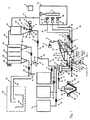
図1は、後に加熱炉(図1には図示せず)内の対象物2上に融着される塗装用粉体を用いた対象物2の噴霧塗装用の本発明による粉体塗装設備1の例示的な実施形態を概略的に示す図である。粉体塗装設備1の運転を制御するために1つまたは複数の電子制御装置3が設けられる。
FIG. 1 shows a
粉体ポンプ4は、塗装用粉体の空気搬送用に設けられる。これらの粉体ポンプは、搬送圧縮空気としての役割を果たす圧縮空気によって、塗装用粉体が粉体容器から吸引されて流れ込む粉体噴射装置であってもよく、その後、搬送圧縮空気と塗装用粉体の混合物が共に容器内にまたは噴霧装置に流れる。
The
例えば、好適な粉体噴射装置が、欧州特許第0412289号明細書に開示されている。 For example, a suitable powder injection device is disclosed in EP 0412289.
圧縮空気によって少量の粉体部分を順次搬送するこれらの種類のポンプを粉体ポンプ4として使用することも可能であり、いずれの場合も、少量の粉体部分(粉体量)が粉体室内に貯蔵され、それから、圧縮空気によって粉体室の外に押し出される。圧縮空気は、粉体部分の後側に留まり、粉体部分をその前方に押し出す。圧縮空気が、ポンプ出口経路を通じて、スラグなどの、貯蔵された粉体部分をその前方に押し出すので、これらの種類のポンプは、圧縮空気押し出しポンプまたはスラグ搬送ポンプと呼ばれることもある。例えば、凝集した塗装用粉体を搬送するためのこのような種々の粉体ポンプが、以下の文献で知られている。独国特許出願公開第10353968号明細書、米国特許第6,508,610号明細書、米国特許出願公開第2006/0193704号明細書、独国特許出願公開第10145448号明細書、または国際公開第2005/051549号パンフレット。
It is also possible to use these types of pumps that sequentially convey a small amount of powder by compressed air as the
本発明は、上記種類の粉体ポンプのうちの1つに限定されるものではない。 The present invention is not limited to one of the above types of powder pumps.
塗装粉体を空気搬送して塗装用粉体を流動化させる圧縮空気を生成するために、対応する圧力設定要素8(例えば、圧力調整器および/または弁)を介して種々の装置に接続された圧縮空気源6が存在する。 Connected to various devices via corresponding pressure setting elements 8 (eg, pressure regulators and / or valves) to produce compressed air that pneumatically conveys the coating powder and fluidizes the coating powder. A compressed air source 6 is present.
粉体供給業者からの新粉体は、新粉体経路16または18の粉体ポンプ4によって供給業者の容器から篩装置10に給送され、この容器は、粉体量が例えば10〜50kg、例えば25kgの例えば寸法的に安定した容器状もしくは袋状の例えば小型容器12、または、粉体量が例えば100kg〜1000kgの例えば同様に寸法的に安定した容器状もしくは袋状の例えば大型容器14であってもよい。篩装置10は、振動子11を備えてもよい。以下の説明において、用語「小型容器」および「大型容器」は、いずれか一方の種類の容器に関して明示的に言及される場合を除き、「寸法的に安定した容器」および「寸法的に安定していない可撓性の袋」の両方を意味する。
The new powder from the powder supplier is fed from the supplier's container to the
篩装置10により篩い分けされた塗装用粉体は、重力によって、または好ましくは、いずれの場合も粉体ポンプ4によって、粉体入口開口部26,26’に通じる1つまたは複数の粉体給送経路20,20’を介して寸法的に安定した粉体容器24の粉体室22内に搬送される。粉体室22の容積は、新粉体用の小型容器12の容積よりも実質的に小さいことが好ましい。
The coating powder screened by the sieving
本発明による解決策の考えられる一実施態様によれば、粉体容器24への少なくとも1つの粉体給送経路20,20’の粉体ポンプ4は、圧力空気押し出しポンプである。この場合、粉体給送経路20の最初の区間は、篩装置10により篩い分けされた粉体が、弁(例えば、ピンチ弁)を通って落下するポンプ室としての役割を果たすことができる。粉体給送経路20は、前記ポンプ室が一定量の粉体部分を収容した時点で、弁の閉鎖により篩装置10から流れに関して切り離される。次に、粉体部分は、粉体給送経路20,20’を通じて粉体室22内に圧縮空気によって押し込まれる。
According to one possible embodiment of the solution according to the invention, the
粉体経路38を通じて噴霧装置40に塗装用粉体を搬送する粉体ポンプ4(例えば、粉体噴射装置)は、粉体容器24の1つまたは好ましくは2つ以上の粉体出口開口部36に接続される。噴霧装置40は、塗装の対象であり、好ましくは塗装用筐体(coating cubical)43に配置された対象物2に塗装用粉体42を噴霧するための噴霧ノズルまたは回転アトマイザを有することができる。
A powder pump 4 (e.g., a powder injection device) that transports powder for coating to the
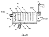
粉体出口開口部36は、図1に図示する通り、粉体容器24の壁に配置可能であり、その壁は粉体入口開口部26,26’が配置された壁の反対側に位置する。しかしながら、図2aおよび図2bに図示する粉体容器24の実施形態では、粉体出口開口部36は、粉体入口開口部26,26’が位置する壁と隣接する壁に配設される。粉体出口開口部36は、粉体室22の底部近傍に配設されることが好ましい。
As shown in FIG. 1, the powder outlet opening 36 can be disposed on the wall of the
粉体室22の大きさは、塗装用粉体容積1.0kg〜12.0kg、好ましくは2.0kg〜8.0kgの範囲内にあると好ましい。他の態様によれば、粉体室22の大きさは、好ましくは500cm3〜30,000cm3、好ましくは2,000cm3〜20,000cm3である。粉体室22の大きさは、連続的な噴霧塗装運転が可能であるが、粉体の変更のために塗装を中断して、迅速にかつ好ましくは自動的に、粉体室22を洗浄することができるように、粉体出口開口部36およびその出口開口部に接続された粉体経路38の数に応じて選択される。
The size of the
粉体室22は、粉体容器24内に収容された塗装用粉体を流動化させるための流動化装置30を備えることができる。流動化装置30は、開気孔を有するかまたは細孔を備え、圧縮空気は透過するが塗装用粉体は透過しない材料で作られた少なくとも1つの流動化壁を含む。図1に示していないが、粉体容器24については、流動化壁が、粉体容器24の底部を形成し、粉体室22と流動化圧縮空気室との間に配設されると有利である。流動化圧縮空気室は、圧力設定要素8を介して圧縮空気源6に接続可能でなくてはならない。
The
塗装の対象である対象物2に付着しない塗装用粉体42は、ファン46の吸引気流によって余剰粉体経路44を介してサイクロン分離器48内に余剰粉体として吸引される。余剰粉体は、サイクロン分離器48内の吸引気流から可能な限り分離される。次に、分離された粉体部分は、回収粉体としてサイクロン分離器48から粉体回収経路50を介して篩装置10に導かれ、そこで、回収粉体単独でまたは新粉体と混合されて篩装置10を通過し、粉体給送経路20,20’を介して再び粉体室22内に入る。
The
図1の点線51により概略的に図示する通り、粉体の種類および/または粉体汚損の程度に応じて、篩装置10から粉体回収経路50を切り離し、回収粉体を廃棄容器内に導くという選択肢も与えられる。粉体回収経路50は、篩装置10から粉体回収経路を切り離す必要がなくなるように、この粉体回収経路を篩装置10または廃棄容器に選択的に接続することができるダイバータ52を備えてもよい。
As schematically illustrated by the dotted
制御装置3および粉体給送経路20,20’の粉体ポンプ4によって粉体室22内への塗装用粉体の給送を制御するために、粉体容器24は、1つ以上のセンサ(例えば、2つのセンサS1および/またはS2)を有してもよい。例えば、下側のセンサS1は粉面レベルの下限を検出し、上側センサS2は粉面レベルの上限を検出する。
In order to control the feeding of the powder for coating into the
サイクロン分離器48の下端部48−2は、回収粉体用の貯蔵容器として設計および使用可能であり、また、この目的で、1つ以上のセンサ(例えば、2つのセンサS3および/またはS4)を備えることができ、これらのセンサは制御装置3に機能的に接続される。その結果、サイクロン分離器48内に回収粉体が十分にある場合、噴霧装置40によって噴霧塗装運転に十分な量の回収粉体を、篩装置10を通じて粉体室22に給送するために、新粉体経路16および18を通じた新粉体の給送を(例えば、自動的に)停止することができる。このための回収粉体が、サイクロン分離器48内にもはや十分にない場合、新粉体給送経路16または18を通じた新粉体の給送に自動的に切り替えることができる。更に、新粉体および回収粉体が互いに混合されるように、これらの粉体を篩装置10に同時に給送するという選択肢もある。
The lower end 48-2 of the
サイクロン分離器48からの排気が、排気経路54を介してアフターフィルタ装置56内に入り、アフターフィルタ装置内の1つまたは複数のフィルタ要素58を通じてファン46に至り、ファンの下流に、外部環境に流れ出る。フィルタ要素58は、フィルタバッグまたはフィルタカートリッジまたはフィルタ板または類似のフィルタ要素であってもよい。フィルタ要素58によって気流から分離された粉体は、通常は廃棄粉体であり、重力によって廃棄容器内に落下する、あるいは、図1に示す通り、(各々粉体ポンプ4を含む)1つまたは複数の廃棄経路60を介して、廃棄ステーション63にある廃棄容器62内に搬送可能である。
Exhaust from the
粉体の種類および粉体塗装状態に応じて、廃棄粉体が、塗装回路に再進入するために篩装置10に再び回収されてもよい。これは、廃棄経路60のダイバータ59および分岐経路61によって図1に概略的に図示されている。
Depending on the type of powder and the state of powder coating, the waste powder may be collected again by the sieving
(種々の色を各々短期間だけ噴霧する)多色運転(multi−color operation)中は、通例、サイクロン分離器48およびアフターフィルタ装置56が使用され、アフターフィルタ装置56からの廃棄粉体が廃棄容器62内に入る。サイクロン分離器48の粉体分離効率は、一般に、アフターフィルタ装置56の分離効率よりも低いが、前記サイクロン分離器の洗浄はアフターフィルタ装置56よりも更に迅速に行うことができる。(同じ粉体を長期間使用する)単色運転中は、サイクロン分離器48を省略し、排気経路54の代わりに余剰粉体経路44をアフターフィルタ装置56に接続し、(この場合、回収の対象である粉体を収容する)廃棄経路60を回収粉体経路として篩装置10に接続することができる。
During multi-color operation (spraying various colors each for a short period of time),
そして通例、単色運転中、問題のある塗装用粉体が含まれている場合に限り、サイクロン分離器48をアフターフィルタ装置56と組み合わせて使用する。この場合、サイクロン分離器48からの回収粉体のみが、粉体回収経路50を介して篩装置10に給送され、その一方で、アフターフィルタ装置56からの廃棄粉体は、廃棄物として廃棄容器62内にまたはアフターフィルタ装置56の出口開口部の真下に廃棄経路60を介さずに載置可能な別の廃棄容器内に入る。
In general, the
サイクロン分離器48の下端は、出口弁64(例えば、ピンチ弁)を有することができる。更に、前記出口弁64より上側の、サイクロン分離器48の下端部48−2の下端内または下端に、塗装用粉体を流動化させる流動化装置66を設けることができ、この端部は貯蔵容器として設計される。流動化装置66は、開気孔を有するかまたは細孔を備え、圧縮空気は透過するが塗装用粉体は透過しない材料で作られた少なくとも1つの流動化壁80を含む。流動化壁80は、粉体路と流動化圧縮空気室81との間に配設される。流動化圧縮空気室81は、圧力設定要素8を介して圧縮空気源6に接続可能である。
The lower end of the
新しい塗装用粉体を取り出すために、新粉体経路16および/または18は、供給業者の容器12または14内に浸漬可能な粉体搬送チューブ70にその新粉体経路の上流端において流れに関して、直接または粉体ポンプ4により、接続可能である。粉体ポンプ4は、新粉体経路16または18の始端、終端もしくは途中に、または粉体搬送チューブ70の上端もしくは下端に配設することができる。
In order to remove the new coating powder, the
図1は、新粉体用の小型容器として、袋受けホッパ74内の新粉体用の粉体袋12を示している。粉体袋12は、袋開口部が袋の上端にある状態で、袋受けホッパ74により画定された形状で保持される。袋受けホッパ74は、一対の秤または計量センサ76上に配設することができる。その種類に応じて、前記一対の秤または計量センサ76は、袋受けホッパ74の重量を差し引いた後、小型容器12内の塗装用粉体の重量ひいてはその量にも相当する画面表示および/または電気信号を生成することができる。少なくとも1つの振動する振動子78は、袋受けホッパ74に配設されることが好ましい。
FIG. 1 shows a powder bag 12 for new powder in a
各袋受けホッパ74に、2つ以上の小型容器12を設けることができる、および/または(代替的に使用可能である)2つ以上の大型容器14を設けることができる。これにより、ある容器から別の小型容器12または大型容器14の迅速な切り替えが可能になる。
Each
図1に図示していないが、原則として、篩装置10が、粉体容器24に一体化されることが考えられる。更に、新粉体が十分に良好な品質である場合、篩装置10を除外してもよい。この場合、経路44および55の回収粉体を篩い分けするために、更に、例えば、サイクロン分離器48の上流側もしくは下流側またはサイクロン分離器48自体に分離篩を使用するという選択肢もある。回収粉体もまた、その粉体の品質が再利用するのに十分に良好である場合、篩を必要としない。
Although not shown in FIG. 1, in principle, it is conceivable that the
粉体入口開口部26,26’は、粉体容器24の側壁に、好ましくは粉体室22の底部近傍に配設される。図2aおよび図2bに図示する粉体容器24の例示的な実施形態では、少なくとも1つの残留粉体出口33が、粉体容器24の同一の側壁に更に設けられ、この残留粉体出口を通じて、洗浄運転中に粉体室22内に導入された洗浄圧縮空気の助けにより、残留粉体を粉体室22の外に追い出すことができる。
The
洗浄運転中に、粉体室22内に洗浄圧縮空気を導入できるように、粉体容器24は、側壁に少なくとも1つの洗浄圧縮空気入口32−1,32−2を有する。粉体塗装設備1の洗浄運転中、洗浄圧縮空気を粉体室22に給送するために、洗浄圧縮空気入口32−1,32−2が、洗浄圧縮空気給送経路101−1,101−2,101−3を介して圧縮空気源6に流れに関して接続される。各洗浄圧縮空気入口32−1,32−2は、粉体容器24の側壁に入口開口部を有することが好ましく、その入口開口部は、塗装用粉体が、粉体塗装設備1の粉体塗装運転中に、必要なときに必要に応じて、粉体室22に給送される粉体入口開口部26,26’と同一である。
The
以下、図2aおよび図2bに図示する粉体容器24を参照しながら、粉体室22を洗浄する運転について更に詳細に説明する。
Hereinafter, the operation of cleaning the
更に、洗浄圧縮空気入口32−1,32−2の入口開口部が設けられた、粉体容器24の側壁に、残留粉体出口33の少なくとも1つの出口開口部があり、この残留粉体出口を通じて、粉体塗装設備1の洗浄運転において粉体室22内に導入された洗浄圧縮空気の助けにより、残留粉体が粉体室22の外に追い出される。
Further, at least one outlet opening of the residual powder outlet 33 is provided on the side wall of the
既に述べた通り、粉体容器24は、少なくとも粉体塗装設備1の粉体塗装運転中に粉体室22内に流動化圧縮空気を導入するために、流動化装置30を具備している。更に、粉体容器24は、圧力を均一にする目的で、粉体室22内に導入された流動化圧縮空気を再び吐出できる出口開口部を備えた少なくとも1つの流動化圧縮空気出口31を有する。流動化圧縮空気出口31の出口開口部は、残留粉体出口33の出口開口部と同一であることが好ましい。
As already described, the
以下、図2aおよび図2bの例を参照しながら、粉体塗装設備1用の粉体供給装置の粉体容器24の例示的な実施形態について詳細に説明する。
Hereinafter, an exemplary embodiment of the
図2aおよび図2bに図示する粉体容器24は、特に、図1の例を参照しながら前述した粉体塗装設備1の一部として相応しい。
The
図2aに図示する通り、例示的な実施形態は、カバー23により閉鎖されたまたは閉鎖可能な粉体容器24を含み、カバー23が、好ましくは迅速に解除可能な接続を介して、粉体容器24に接続可能である。
As illustrated in FIG. 2a, an exemplary embodiment includes a
図2aに図示する粉体容器24は、塗装用粉体を受け入れる実質的に直方体の粉体室22を有する。圧縮空気経路を介して粉体室22から残留粉体を除去するための粉体塗装設備1の洗浄運転において、圧縮空気源6が接続可能である少なくとも1つの洗浄圧縮空気入口32−1,32−2が、粉体室22内に洗浄圧縮空気を導入するために、粉体容器24の側壁24−3に設けられる。更に、出口開口部を有する残留粉体出口33が粉体容器24の上記側壁24−3に設けられ、この出口開口部を介して、粉体塗装設備1の洗浄運転中に粉体室22内に導入された洗浄圧縮空気の助けにより、残留粉体を粉体室22の外に追い出すことができる。
The
特に図2bの例から推測できるように、粉体容器24の例示的な実施形態では、合計2つの洗浄圧縮空気入口32−1,32−2が設けられ、2つの洗浄圧縮空気入口32−1,32−2各々が入口開口部を有する。その一方で、出口開口部を1つだけ備える残留粉体出口33が1つだけ設けられ、洗浄圧縮空気入口32−1,32−2の2つの入口開口部が、残留粉体出口34の出口開口部から鉛直方向に間隔を置いて配置される。
In particular, as can be inferred from the example of FIG. 2 b, in the exemplary embodiment of the
詳細には、特に図2bの例から推測できるように、例示的な実施形態では、残留粉体出口33の出口開口部が、粉体容器24の側壁24−3の上部領域に設けられ、洗浄圧縮空気入口32−1,32−2の入口開口部が、粉体容器24の側壁24−3の下部領域に設けられる。一方では入口開口部、そして他方では出口開口部の前記の特別な構成で達成される効果により、粉体塗装設備1の洗浄運転中、まず第1に、粉体容器24の底壁24−2にまだ付着している可能性のある残留粉体が、粉体室22内に導入された洗浄圧縮空気により巻き上げられ、残留粉体出口33の出口開口部を介して洗浄圧縮空気と共に粉体室22の外に運び出される。
In particular, as can be inferred from the example of FIG. 2b in particular, in the exemplary embodiment, the outlet opening of the residual powder outlet 33 is provided in the upper region of the side wall 24-3 of the
また、図2aに示す通り、空気の渦(air roll)35が粉体室22内に形成される。洗浄運転中に、粉体容器24の壁24−1,24−2,24−3,24−4,24−5および粉体容器24のカバー23にまだ付着している可能性のある残留粉体を、前記空気の渦35により効果的に離脱させ、粉体室22の外に運び出すことができる。残留粉体出口33の出口開口部が、2つの洗浄圧縮空気入口32−1,32−2の入口開口部をも設けられる粉体容器24のその側壁24−3の上部領域に配設されることにより、粉体室22内に導入された洗浄圧縮空気は、(粉体容器24の側壁24−1,24−3,24−4,24−5および底壁24−2ならびに粉体容器24のカバーの内壁の周囲に流れた後)方向に比較的大きな変化のない状態で、再び粉体室22の外に導かれ得る。この結果、洗浄圧縮空気と共に移送された残留粉体の少なくとも大部分を、粉体室22から洗浄圧縮空気と一緒に吐出することができる。
Also, as shown in FIG. 2 a, an
図2aおよび図2bに示す例示的な実施形態では、2つの洗浄圧縮空気入口32−1,32−2の入口開口部は、粉体塗装設備1の粉体塗装運転において、必要なときに必要に応じて、粉体室22内に塗装用粉体を給送するために、粉体室22の外側に粉体給送経路20,20’を接続可能な粉体入口開口部としての役割を果たす。したがって、図示の実施形態では、各洗浄圧縮空気入口32−1,32−2は、粉体塗装設備1の粉体塗装運転において、必要なときに、粉体給送経路20,20’に流れに関して接続された粉体入口20−1,20−2の機能を得る。しかし、当然ながら、洗浄圧縮空気入口32−1,32−2に加えて、別の粉体入口20−1,20−2を設けることも考えられる。
In the exemplary embodiment shown in FIGS. 2 a and 2 b, the inlet openings of the two cleaning compressed air inlets 32-1 and 32-2 are necessary when necessary in the powder coating operation of the
図2aおよび図2bに図示する実施形態では、粉体塗装設備1の粉体塗装運転において、2つの粉体入口20−2,20−1の一方の入口開口部は、必要なときに必要に応じて、新粉体を給送する役割を果たし、2つの粉体入口20−2,20−1の他方の入口開口部は、必要なときに必要に応じて、回収粉体を給送する役割を果たす。しかし、当然ながら、粉体塗装設備1の粉体塗装運転において、回収粉体および新粉体の両方が、必要なときに必要に応じて、同一の粉体入口20−2,20−1から入口開口部を介して供給可能であることも考えられる。
In the embodiment illustrated in FIGS. 2a and 2b, in the powder coating operation of the
図2aおよび図2bに図示する実施形態では、粉体室22内に流動化圧縮空気を導入するために、流動化装置30を設けることが好ましい。流動化圧縮空気は、端壁、側縦壁、底壁または天壁を通じて粉体室22内に導入可能である。図示の実施形態によれば、粉体室22の底壁24−2は、流動化床として設計されている。流動化床は、粉体吐出装置の助けにより前記塗装用粉体を簡単に取り出すことができるように、粉体塗装設備1の粉体塗装運転中に、粉体室22内で塗装用粉体を浮遊状態にする(流動化させる)ために、底壁より下に配設された流動化圧縮空気室からの流動化圧縮空気が粉体室22内に上向きに流入できる複数の開気孔または小さな流通開口を有する。流動化圧縮空気は、流動化圧縮空気入口を通じて流動化圧縮空気室に給送される。
In the embodiment illustrated in FIGS. 2 a and 2 b, a fluidizing
流動化装置30の運転中に、粉体室22内の圧力が予め定められた最大圧力を超えないように、粉体室22は、粉体室22内に導入された流動化圧縮空気を吐出するためおよび圧力を均一にするための出口開口部を備えた少なくとも1つの流動化圧縮空気出口31を有する。特に、少なくとも1つの流動化圧縮空気出口31の出口開口部は、粉体室22内の流動化装置30の運転中に、正圧が大気圧よりも最大0.5bar優勢になるような寸法とされるべきである。
During operation of the fluidizing
図2aおよび図2bに図示する実施形態では、残留粉体出口33の出口開口部は、流動化圧縮空気出口31の出口開口部と同一である。しかし、当然ながら、流動化圧縮空気出口31を、例えば、粉体容器24のカバー23に設けることも可能である。
In the embodiment illustrated in FIGS. 2 a and 2 b, the outlet opening of the residual powder outlet 33 is the same as the outlet opening of the fluidized compressed air outlet 31. However, it goes without saying that the fluidized compressed air outlet 31 can be provided, for example, in the
特に図2aの例で推測できるように、図示の実施形態では、流動化圧縮空気出口31は、粉体塗装設備1の粉体塗装運転中に、粉体室22から粉体が放出されるのを防止するために、立上り管27に粉体室22の外側で接続されたまたは接続可能な通気経路を有する。
In particular, as can be inferred from the example of FIG. 2 a, in the illustrated embodiment, the fluidized compressed air outlet 31 discharges powder from the
粉体室22内に導入された流動化圧縮空気を吐出するために、更に、好ましくは粉体室22の上部領域内に突出する通気経路を設けることも考えられる。通気経路の突出端は、排出設備(extraction installation)の排出漏斗内に突出可能である。前記排出設備を、例えば、ブースタ(エアムーバ)として形成することができる。(エアムーバとしても知られる)ブースタは、コアンダ効果に基づき動作し、その運転のために、少量で給送しなければならない通例の圧縮空気を必要とする。前記空気量は、周囲圧力よりも高い圧力を有する。ブースタは、排出漏斗内で、大量および低圧で、高速の気流を発生させる。それゆえ、ブースタは、通気経路または流動化圧縮空気出口31との併用で特に良好に適している。
In order to discharge the fluidized compressed air introduced into the
図2aに図示する例示的な実施形態では、粉体容器24は、粉体室22内の最大許容粉面レベルを検出するための非接触で動作するレベルセンサS1,S2を有する。この接続では、少なくとも1つの粉体入口20−1,20−2の入口開口部を介して粉体室22に新粉体または回収粉体を、好ましくは自動的に、給送するために、最小粉面レベルを検出し、前記最小粉面レベルに達し次第またはこのレベルより下に下がり次第、制御装置3に対応するメッセージを出力するように粉体容器24に対して配設される更なるレベルセンサを設けることが考えられる。
In the exemplary embodiment illustrated in FIG. 2 a, the
粉体室22内の粉面レベルを検出するためのレベルセンサS1,S2は、非接触で動作するレベルセンサであることが好ましく、粉体室22の外側に配設されるとともに粉体室から隔離される。これにより、レベルセンサS1,S2の汚損が防止される。レベルセンサS1,S2は、粉面レベルが一定の高さに達したときに信号を発生する。例えば、所定の最大高さレベルを検出するおよび所定の最低高さレベルを検出するために、このような複数の粉面レベルセンサS1,S2を異なる高さに配設することも可能である。
The level sensors S1 and S2 for detecting the powder level in the
粉体噴射装置4が粉体室22から塗装用粉体を取り出す期間中であっても、粉体室内に所定の高さレベルまたは所定の高さレベルの領域を維持し、噴霧装置40(または他の容器内)に前記塗装用粉体を空気搬送するために、少なくとも1つのレベルセンサS1,S2の信号を粉体入口20−1,20−2から粉体室22内への塗装用粉体の自動的な粉体給送の制御に使用することが好ましい。
Even during the period in which the
このような粉体噴霧塗装運転中、洗浄圧縮空気は、導かれるとしても減圧下で粉体室22内にのみ導かれる。
During such powder spray coating operation, the cleaning compressed air is guided only into the
塗装を中断して粉体室22を洗浄するために、例えば、ある種の粉体を別の種類の粉体に変更する間に、少なくとも1つの洗浄圧縮空気入口32−1,32−2を通じて粉体室22に洗浄圧縮空気が給送される。洗浄圧縮空気は、粉体容器24の内部に空気の渦35を発生させ、前記空気の渦は、粉体容器24の内壁にまだ付着している可能性のある残留粉体を離脱させ、残留粉体出口34を通じて前記残留粉体を粉体室22の外に追い出す。
In order to interrupt painting and clean the
更に、図面には明確に図示していないが、粉体室22内に広がる空気圧を測定するための装置を設けることも考えられる。これは、一般に粉体容器24が高圧容器として設計されていないので、粉体塗装設備1の粉体塗装運転中の流動化圧縮空気の導入および粉体塗装設備1の洗浄運転における洗浄圧縮空気の導入により、粉体容器24の内部に過剰な正圧を蓄積しないようにするために注意を必要とする限りにおいて重要である。この点では、粉体室22内の最大許容正圧が0.5barの値を超えないと好ましい。
Further, although not clearly shown in the drawings, it is conceivable to provide a device for measuring the air pressure spreading in the
最後に述べる実施形態では、特に、粉体室22内で測定された空気圧が、連続的にまたは所定の時間にもしくは所定の事象で制御装置3に入力され、粉体室22に単位時間当たりに給送される流動化圧縮空気の量、および/または少なくとも1つの流動化圧縮空気出口31を介して粉体室22から単位時間当たりに吐出される流動化圧縮空気の量が、粉体室22内に広がる空気圧に応じて、好ましくは自動的に、調節されることが考えられる。これに対して、粉体塗装設備1の洗浄運転中に、制御装置3の助けにより、粉体室22に単位時間当たりに給送される洗浄圧縮空気の量、および/または少なくとも1つの残留粉体出口33を介して単位時間当たりに吐出される洗浄圧縮空気の量が、粉体室22内に広がる空気圧に応じて、好ましくは自動的に、調節されると好ましい。
In the last-described embodiment, in particular, the air pressure measured in the
図2aの例から推測できるように、例示的な実施形態では、好ましくは重力によって、粉体室22から塗装用粉体を除去するために、必要なときに必要に応じて、ピンチ弁21の助けにより開放可能である、粉体出口25が、粉体容器24の底壁24−2に設けられる。特に、この粉体出口は、色または粉体に変更がある場合で、古い種類の塗装用粉体が粉体室22内にまだ存在するときには必ず必要となる。
As can be inferred from the example of FIG. 2a, in an exemplary embodiment, the
粉体室22は、粉体室22の底面と側面が、縁、特に直角の縁により互いに連結された角形の内面形状を有することが特に好ましい。粉体室22の前記角形の内面形状により、粉体塗装設備1の洗浄運転中に、粉体室22の内部に形成される空気の渦35が、層流境界層よりむしろ乱流境界層を確実に形成するようにし、これにより、粉体容器24の内壁に付着している残留粉体の除去を容易にする。
It is particularly preferable that the
粉体塗装設備1の洗浄運転中に、粉体容器24の内部にできるだけ理想的な空気の渦35を形成できるように、粉体室22の高さが、180mm〜260mm、好ましくは200mm〜240mm、および更に好ましくは220mmであり、粉体室22の幅が、140mm〜220mm、好ましくは160mm〜200mm、および更に好ましくは180mmであり、粉体室22の長さが、510mm〜590mm、好ましくは530mm〜570mm、および更に好ましくは550mmであると好ましいことが実証されている。粉体室22が前記規定の寸法であることを前提として、粉体容器24の共通の端壁24−3に、少なくとも1つの洗浄圧縮空気入口32−1,32−2および少なくとも1つの残留粉体出口33を更に設けるべきである。
The height of the
更に、図2aおよび図2bに示す粉体供給装置は、1つ、好ましくは2つ以上の粉体噴射装置4によって粉体ホース38を介して噴霧装置40に塗装用粉体を搬送することができ、また前記噴霧装置によって塗装対象物2に前記塗装用粉体を噴霧できるように、少なくとも1つの粉体吐出装置を有する。
Furthermore, the powder supply apparatus shown in FIGS. 2 a and 2 b can convey the coating powder to the
図2aに図示する通り、対応する粉体吐出開口部36が、粉体容器24の室壁24−3および24−4に設けられる。図示の実施形態では、粉体塗装設備1の粉体塗装運転中に粉体室22から塗装用粉体を吸引することができ、また前記塗装用粉体を噴霧装置40に給送できるように、粉体吐出開口部36各々が、関連する粉体噴射装置4に流れに関して接続される。粉体吐出開口部36は、流動化させた塗装用粉体を吸引するための有効領域を増加させるために楕円形であることが好ましい。
As shown in FIG. 2 a, corresponding
粉体噴射装置4によって粉体室22から可能な限りすべての塗装用粉体を取り出すことができるように、粉体吐出開口部36は、粉体室22内のできるだけ低い位置に配設される。粉体噴射装置4は、最も高い粉面レベルよりも高い位置に配置されることが好ましく、各々(図2aおよび図2bの点線により図示する)粉体吐出流路13を介して、粉体吐出開口部36のうちの1つに接続される。粉体噴射装置4が、最大粉面レベルよりも高く配設されることにより、粉体噴射装置4のスイッチが入っていない場合に、粉体室22から塗装用粉体が上昇して粉体噴射装置4内に入り込むことを回避する。
The
粉体吐出流路13は、例えば、粉体室22内に突出するディップ管内または(図2aおよび図2bによる実施形態で規定する通り)粉体容器24の側壁24−4,24−5内に形成されてもよい。粉体吐出流路13が実際にどのように実現されるかに関わらず、粉体吐出流路13の直径が、最大10mm〜少なくとも3mm、および好ましくは8mm〜5mmであると好ましい。それゆえ、粉体吐出流路13の直径は、従来技術で知られる解決策と比較して縮小されている。
The
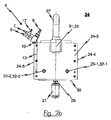
図2bに図示する通り、各粉体噴射装置4は、噴射装置4の負圧領域内で負圧を発生させる搬送圧縮空気の調整給送のための、圧縮空気源に接続可能な、搬送圧縮空気接続部5を有し、これにより、粉体室22から粉体吐出流路13を介して塗装用粉体を吸引し、次に、粉体ホース38により粉体出力(受けノズル9)を通じて受け取り点(上記噴霧装置40または更なる粉体容器24であってもよい)に前記塗装用粉体を搬送する。粉体の搬送を支援するために、粉体噴射装置4は、粉体出力9の搬送圧縮空気粉体流に追加の圧縮空気を給送するための追加の圧縮空気入口または調量空気入口7を備えることができる。
As shown in FIG. 2 b, each
分かり易くする理由から図示していないが、図2aおよび図2bに図示する実施形態では、複数の粉体噴射装置4が用いられ、複数の粉体噴射装置の粉体吐出流路13が粉体容器24の対向する2つの側壁24−4,24−5内に形成される。しかし、当然ながら、粉体吐出流路13が、粉体容器24の側壁内に形成されるのではなく、むしろ粉体吸引管として形成されることも考えられる。
Although not shown for reasons of clarity, in the embodiment shown in FIGS. 2a and 2b, a plurality of
図2bの例から推測できるように、この例示的な実施形態では、少なくとも1つの粉体噴射装置4が、搬送圧縮空気の調整給送のための、圧縮空気源に接続されたまたは接続可能な、搬送圧縮空気接続部5と、調量圧縮空気の調整給送のための、同様に圧縮空気源6に接続されたまたは接続可能な、調量圧縮空気接続部7とを有し、粉体噴射装置4に給送された搬送圧縮空気が、粉体噴射装置4に割り当てられた粉体吐出流路13を介して粉体室22から塗装用粉体を吸引できるようにして、粉体噴射装置4の負圧領域内に負圧を発生させ、調量圧縮空気接続部7が、粉体噴射装置4の負圧領域の下流側に設けられる。
As can be inferred from the example of FIG. 2b, in this exemplary embodiment, at least one
図2bの例からは推測できないが、少なくとも1つの粉体噴射装置4はまた、粉体噴射装置4の搬送圧縮空気接続部5を介して給送された搬送圧縮空気がベンチュリノズルを流れ、その結果、ベンチュリノズルの最も狭い横断面領域で動圧が低下して負圧領域を形成するようにして配設および形成された、ベンチュリノズルを有することが好ましい。
Although not inferred from the example of FIG. 2b, the at least one
図2bに示す実施形態では、少なくとも1つの粉体噴射装置4が、粉体出口を形成するために粉体噴射装置4の負圧領域の下流側に配設および形成された、交換可能な受けノズル9を有し、粉体噴射装置4の助けにより粉体室22から吸引された塗装用粉体を噴霧装置40に搬送するために、粉体経路38(特に、粉体ホース)に接続されるまたは接続可能である。
In the embodiment shown in Fig. 2b, at least one
図2bに示す特別な実施形態では、少なくとも1つの粉体噴射装置4はまた、粉体塗装設備の洗浄運転における洗浄圧縮空気の調整給送のための、圧縮空気源に接続されたまたは接続可能な、洗浄圧縮空気接続部17を有し、洗浄圧縮空気接続部5が、粉体噴射装置4の負圧領域の下流側に設けられる。
In the special embodiment shown in FIG. 2b, the at least one
当然ながら、他の実施態様も考えられるが、図2bに図示する通り、洗浄圧縮空気接続部17が、分岐管、特にT字形部材を介して調量圧縮空気接続部7に接続可能である。
Of course, other embodiments are conceivable, but as shown in FIG. 2b, the cleaning
特に、粉体塗装設備の洗浄運転において搬送圧縮空気接続部5に単位時間当たりに給送される搬送圧縮空気の量を調整するために、手動操作可能なまたは自動作動式の圧力調整装置が設けられると好ましい。圧力調整装置は、好ましくは、粉体塗装設備の洗浄運転において洗浄圧縮空気接続部17に単位時間当たりに給送される洗浄圧縮空気の量を調整するように設計されるべきである。
In particular, in order to adjust the amount of the transport compressed air supplied per unit time to the transport compressed
代替案としてまたはこれに追加して、圧力調整装置が、粉体塗装設備の洗浄運転において調量圧縮空気接続部7に単位時間当たりに給送される調量圧縮空気の量を調整するように設計されると好ましい。特に、ここで圧力調整装置は、特に色または粉体に変更がある場合、少なくとも1つの粉体噴射装置4に単位時間当たりに給送される圧縮空気総量の少なくとも20%、および好ましくは25%〜50%が、粉体吐出流路13を通じて粉体室22内にパージ空気として流れ、少なくとも1つの粉体噴射装置4に単位時間当たりに給送される圧縮空気総量の残りの量が、粉体経路38を通じて噴霧装置40にパージ空気として流れるようにして、搬送圧縮空気接続部5に単位時間当たりに給送される搬送圧縮空気の量、および/または洗浄圧縮空気接続部17に単位時間当たりに給送される洗浄圧縮空気の量、および/または粉体塗装設備の洗浄運転において調量圧縮空気接続部7に単位時間当たりに給送される調量圧縮空気の量を設定するように設計可能である。
As an alternative or in addition thereto, the pressure regulator adjusts the amount of metered compressed air delivered per unit time to the metered compressed air connection 7 in the washing operation of the powder coating facility. Preferably it is designed. In particular, the pressure regulating device here is at least 20% and preferably 25% of the total amount of compressed air delivered per unit time to the at least one
特に、ここで圧力調整装置は、粉体塗装設備の洗浄運転において粉体噴射装置4に給送される圧縮空気の総量が、粉体噴射装置4に少なくとも10m3/h〜17m3/hの体積流量で給送されるように設計可能であり、圧力調整装置はまた、圧縮空気が粉体吐出流路13を通じて少なくとも3m3/hの体積流量で流れ、圧縮空気が粉体経路38を通じて少なくとも9m3/hの体積流量で流れるようにして、搬送圧縮空気接続部5に単位時間当たりに給送される搬送圧縮空気の量、および/または洗浄圧縮空気接続部17に単位時間当たりに給送される洗浄圧縮空気の量、および/または粉体塗装設備の洗浄運転において調量圧縮空気接続部7に単位時間当たりに給送される調量圧縮空気の量を設定するように設計されることが好ましい。
In particular, where a pressure regulating device, the total amount of the compressed air fed to the
少なくとも1つの粉体噴射装置4ならびに関連する粉体吐出流路13および関連する粉体吐出開口部36から残留粉体を除去するために、また、粉体噴射装置4の粉体出口9に流れに関して接続された、(図2aおよび図2bには明確に図示していない)粉体経路38から残留粉体を除去するために、少なくとも1つの粉体噴射装置の搬送圧縮空気接続部5が、搬送圧縮空気接続部5を介して粉体噴射装置4に圧縮空気を給送するために、圧縮空気源に接続可能である。従来技術で知られる解決策と比較すると、例示的な実施形態では、粉体噴射装置4に割り当てられた粉体吐出流路13が短縮されるように設計され、粉体塗装設備の洗浄運転において少なくとも1つの粉体噴射装置4に単位時間当たりに給送される圧縮空気の量が、粉体噴射装置4において分割され、一方の部分流が粉体吐出流路13を通じて粉体室22内に流入し、他の部分流が粉体噴射装置4の受けノズル9、受けノズルに接続された粉体経路38、および例えば、粉体経路38に接続された噴霧装置40を流れる。粉体噴射装置4に給送された圧縮空気総量の2つの部分流は、パージ空気としての役割を果たし、粉体供給装置の対応する構成要素を洗浄する。
In order to remove residual powder from the at least one
この場合、洗浄運転において搬送圧縮空気接続部5を介して少なくとも1つの粉体噴射装置4に単位時間当たりに給送される搬送空気の少なくとも20%、および好ましくは25%〜50%が、粉体吐出流路13を通じてパージ空気として流れるように、粉体吐出流路13の長さおよび有効径が、粉体経路38の長さおよび有効径に対して一致することが好ましい。特に、粉体吐出流路13の効果的な洗浄を可能にするために、3m3/h〜4m3/hの体積流量が好ましい。
In this case, at least 20%, and preferably 25% to 50% of the carrier air fed per unit time to the at least one
原則として、少なくとも1つの粉体噴射装置4の搬送圧縮空気接続部5が、粉体塗装設備の洗浄運転において、粉体噴射装置4に圧縮空気を少なくとも10m3/h〜15m3/hの体積流量で給送する洗浄圧縮空気源に接続可能であることが考えられる。
In principle, the conveying
(図2aおよび図2bに図示した実施形態で規定する通り)複数の粉体噴射装置4が粉体容器24毎に設けられる場合、複数の粉体噴射装置4は、粉体塗装設備の少なくとも洗浄運転において、圧縮空気が粉体噴射装置4の個々の搬送圧縮空気接続部5に好ましくは10m3/h〜15m3/hの体積流量で選択的に給送されるようにして、制御装置3の助けにより個々にまたはグループで作動可能であると好ましい。
In the case where a plurality of
最終的に、粉体室22が取り外し可能なカバー23を備えていると好ましく、粉体室22への迅速なアクセスを可能にするために、前記カバー23が迅速に解除可能な接続により粉体室22に接続可能であり、これは、例えば、圧縮空気ガンの助けによる手作業での再洗浄に必要となる。カバーと粉体室22との間の迅速に解除可能な接続が、例えば、機械的接続、磁気的接続、空気接続または流体圧接続であってもよい。
Finally, it is preferable that the
本発明は、前述の例示的な実施形態に限定されるものではなく、むしろ本明細書に開示した特徴すべての全体像から得られる。 The present invention is not limited to the exemplary embodiments described above, but rather is derived from an overall picture of all the features disclosed herein.
Claims (19)
‐搬送圧縮空気の調整給送のための、圧縮空気源(6)に接続されたまたは接続可能な、搬送圧縮空気接続部(5)と、
‐調量圧縮空気の調整給送のための、圧縮空気源(6)に接続されたまたは接続可能な、調量圧縮空気接続部(7)と、を有し、
前記粉体噴射装置(4)に給送された前記搬送圧縮空気が、前記紛体噴射装置(4)に割り当てられた前記粉体吐出流路(13)を介して塗装用粉体を前記粉体室(22)から吸引できるように前記粉体噴射装置(4)の負圧領域内に負圧を発生させ、前記調量圧縮空気接続部(7)が前記粉体噴射装置(4)の負圧領域の下流側に設けられる、請求項1〜8のいずれか一項に記載の粉体供給装置。 Said at least one powder injection device (4) is:
A carrier compressed air connection (5) connected to or connectable to a compressed air source (6) for the regulated feeding of the carrier compressed air;
A metered compressed air connection (7) connected to or connectable to a compressed air source (6) for the regulated supply of metered compressed air;
The conveying compressed air fed to the powder injection device (4) passes the powder for coating through the powder discharge passage (13) assigned to the powder injection device (4). A negative pressure is generated in the negative pressure region of the powder injection device (4) so as to be sucked from the chamber (22), and the metering compressed air connection (7) is negative of the powder injection device (4). The powder supply apparatus as described in any one of Claims 1-8 provided in the downstream of a pressure area | region.
‐前記粉体塗装設備の前記洗浄運転における洗浄圧縮空気の調整給送のための、圧縮空気源に接続されたまたは接続可能な、洗浄圧縮空気接続部(17)を有し、
前記洗浄圧縮空気接続部(17)が前記粉体噴射装置(4)の前記負圧領域の下流側に設けられる、請求項9〜11のいずれか一項に記載の粉体供給装置。 Said at least one powder injection device (4) is also:
A cleaning compressed air connection (17) connected to or connectable to a compressed air source for the regulated supply of cleaning compressed air in the cleaning operation of the powder coating facility;
The powder supply device according to any one of claims 9 to 11, wherein the cleaning compressed air connection portion (17) is provided on the downstream side of the negative pressure region of the powder injection device (4).
Applications Claiming Priority (3)
| Application Number | Priority Date | Filing Date | Title |
|---|---|---|---|
| DE102010039473.4A DE102010039473B4 (en) | 2010-08-18 | 2010-08-18 | Powder supply device for a powder coating system |
| DE102010039473.4 | 2010-08-18 | ||
| PCT/US2011/048022 WO2012024358A2 (en) | 2010-08-18 | 2011-08-17 | Powder supplying device for a powder coating installation |
Publications (1)
| Publication Number | Publication Date |
|---|---|
| JP2013536070A true JP2013536070A (en) | 2013-09-19 |
Family
ID=45541055
Family Applications (1)
| Application Number | Title | Priority Date | Filing Date |
|---|---|---|---|
| JP2013524947A Pending JP2013536070A (en) | 2010-08-18 | 2011-08-17 | Powder supply equipment for powder coating equipment |
Country Status (8)
| Country | Link |
|---|---|
| US (1) | US9657740B2 (en) |
| EP (1) | EP2605985B1 (en) |
| JP (1) | JP2013536070A (en) |
| KR (1) | KR20130045362A (en) |
| CN (2) | CN106076686B (en) |
| CA (1) | CA2807953A1 (en) |
| DE (1) | DE102010039473B4 (en) |
| WO (1) | WO2012024358A2 (en) |
Cited By (1)
| Publication number | Priority date | Publication date | Assignee | Title |
|---|---|---|---|---|
| JP2014510624A (en) * | 2011-02-18 | 2014-05-01 | ゲマ スイッツランド ゲーエムベーハー | Device for pneumatically transporting powder and method for cleaning the device |
Families Citing this family (19)
| Publication number | Priority date | Publication date | Assignee | Title |
|---|---|---|---|---|
| DE102012103498A1 (en) * | 2012-04-20 | 2013-10-24 | Reinhausen Plasma Gmbh | Device and method for identifying a substrate and identification thereof |
| DE102012106078A1 (en) * | 2012-07-06 | 2014-05-08 | Reinhausen Plasma Gmbh | Coating device and method for coating a substrate |
| DE102013218326A1 (en) * | 2013-09-12 | 2015-03-12 | Gema Switzerland Gmbh | Powder supply device for a powder coating system |
| JP6015709B2 (en) * | 2014-05-14 | 2016-10-26 | トヨタ自動車株式会社 | Powder supply method for overlaying |
| DE102014223307B4 (en) * | 2014-11-14 | 2020-07-16 | Gema Switzerland Gmbh | Powder container for supplying a spray coating system with coating powder |
| US10226917B2 (en) * | 2015-07-27 | 2019-03-12 | Dmg Mori Seiki Usa | Powder delivery systems and methods for additive manufacturing apparatus |
| US12564849B2 (en) | 2017-02-21 | 2026-03-03 | Gema Switzerland Gmbh | Dense phase powder pump |
| DE102017103487A1 (en) * | 2017-02-21 | 2018-08-23 | Gema Switzerland Gmbh | POWDER SEALING POWER PUMP |
| DE102018204608A1 (en) * | 2017-04-27 | 2018-10-31 | Heidelberger Druckmaschinen Ag | Device for changing the powder type |
| CN106929788A (en) * | 2017-05-02 | 2017-07-07 | 安徽威龙再制造科技股份有限公司 | A kind of multi-element alloy coat of sinking roller and its preparation and spraying method |
| ES2910093T3 (en) * | 2017-11-21 | 2022-05-11 | Siver S R L | Apparatus for coating systems |
| DE102019101930A1 (en) * | 2018-12-27 | 2020-07-02 | Gema Switzerland Gmbh | Powder dispenser with a thin powder pump |
| FR3093019A1 (en) * | 2019-02-25 | 2020-08-28 | Airbus Operations | spray and suction stripping tool |
| KR102220056B1 (en) * | 2019-05-10 | 2021-02-25 | 세메스 주식회사 | Apparatus for supplying powder and system for coating equipment with the apparatus |
| CN110224342A (en) * | 2019-07-10 | 2019-09-10 | 合肥安力电力工程有限公司 | A kind of cable poling auxiliary device |
| CN112718299B (en) * | 2021-04-02 | 2021-07-09 | 成都天本地源科技有限公司 | Vertical intermittent dilute-phase powder material jet conveying device |
| EP4368319A1 (en) * | 2022-11-11 | 2024-05-15 | General Electric Company | Liquid and powder material handling systems within additive manufacturing and methods for their use |
| KR102618729B1 (en) * | 2023-06-02 | 2023-12-27 | 윤성영 | powder mixing device |
| CN116765080B (en) * | 2023-06-21 | 2025-06-06 | 江苏鸿云精密工业有限公司 | A kind of powder coating equipment based on ultrasonic cleaning |
Citations (6)
| Publication number | Priority date | Publication date | Assignee | Title |
|---|---|---|---|---|
| JPS61181559A (en) * | 1985-01-04 | 1986-08-14 | Nippon Sheet Glass Co Ltd | Pneumatic type ejector of powder |
| JPH08175665A (en) * | 1994-12-22 | 1996-07-09 | Kurimoto Ltd | Carrying device for powder coating |
| JPH10323583A (en) * | 1997-05-16 | 1998-12-08 | Pcf Group Inc | Nozzle device and method for dispensing powder paint |
| JP2002096930A (en) * | 2000-09-20 | 2002-04-02 | Nippon Parkerizing Co Ltd | Powder metering device |
| JP2010017628A (en) * | 2008-07-09 | 2010-01-28 | Asahi Sunac Corp | Powder conveyer |
| US20100028090A1 (en) * | 2007-02-02 | 2010-02-04 | Itw Gema Ag | Powder feeding device of a powder spray coating appratus with sieve |
Family Cites Families (71)
| Publication number | Priority date | Publication date | Assignee | Title |
|---|---|---|---|---|
| US2181095A (en) * | 1936-08-19 | 1939-11-21 | Nesaloy Products Inc | Heating torch |
| US2980298A (en) * | 1957-02-18 | 1961-04-18 | J C Hanson | Material dispensing apparatus |
| US3329267A (en) * | 1961-06-15 | 1967-07-04 | Ajem Lab Inc | Apparatus for handling grit |
| DE2020055A1 (en) * | 1970-04-24 | 1971-12-02 | Mueller Ernst Kg | Method and device for covering objects with powdery substances |
| US3797747A (en) * | 1971-09-25 | 1974-03-19 | Hano Grohe Kg Fa | Device for aspirating and admixing additives into a stream |
| US3960323A (en) * | 1971-11-02 | 1976-06-01 | Nordson Corporation | Powder spray system |
| US3870375A (en) * | 1971-11-02 | 1975-03-11 | Nordson Corp | Powder spray system |
| US3809436A (en) * | 1972-05-25 | 1974-05-07 | Cpc Eng Corp | Process for conveyance of ash |
| ZA745832B (en) * | 1973-10-13 | 1975-10-29 | Polysius Ag | Device for the pneumatic withdrawal of fine material from a silo container |
| US3858763A (en) * | 1974-02-14 | 1975-01-07 | John A Mack | Dispensing apparatus for de-icing roadways and like surfaces |
| US4016994A (en) * | 1975-09-16 | 1977-04-12 | Wurster Wilfred A | Mobile vacuum and pneumatic unit |
| US4116367A (en) * | 1975-11-12 | 1978-09-26 | Nippon Steel Corporation | Apparatus for supplying powder to continuous casting mold |
| US4381897A (en) * | 1980-10-06 | 1983-05-03 | Krupp Polysius Ag | Installation for transporting fine-grained material |
| US4615649A (en) * | 1984-10-12 | 1986-10-07 | Nordson Corporation | Powder pump having suction tube deflector |
| US4824295A (en) * | 1984-12-13 | 1989-04-25 | Nordson Corporation | Powder delivery system |
| US4586854A (en) * | 1985-06-12 | 1986-05-06 | Nordson Corporation | Venturi powder pump having rotating diffuser |
| US4730647A (en) * | 1986-12-08 | 1988-03-15 | Nordson Corporation | Powder feeder apparatus |
| US4834544A (en) * | 1987-07-06 | 1989-05-30 | Fuller Company | Fines separation system for pellet blender |
| DE3730438A1 (en) * | 1987-09-10 | 1989-03-23 | Wiederaufarbeitung Von Kernbre | JET PUMP |
| US4900200A (en) * | 1988-06-22 | 1990-02-13 | Matsui Manufacturing Co., Ltd. | Method for transporting powdered or granular materials by pneumatic force with a transport pipe of smaller diameter relative to particale size |
| JPH0444335Y2 (en) * | 1988-10-04 | 1992-10-20 | ||
| US5006019A (en) * | 1989-06-29 | 1991-04-09 | Aec, Inc. | Pneumatic pickup probe |
| DE3926624A1 (en) * | 1989-08-11 | 1991-02-14 | Gema Ransburg Ag | ELECTROSTATIC POWDER COATING DEVICE |
| IL98594A (en) * | 1991-06-24 | 1994-06-24 | Israel State | Device for cleaning surfaces from chemical decontaminants |
| US5226567A (en) * | 1991-10-03 | 1993-07-13 | Dominic A. Sansalone | Garden powder duster |
| US5454256A (en) * | 1992-08-13 | 1995-10-03 | Nordson Corporation | Powder coating system with dew-point detection |
| US5378089A (en) * | 1993-03-01 | 1995-01-03 | Law; R. Thomas | Apparatus for automatically feeding hot melt tanks |
| DE4319726A1 (en) * | 1993-06-15 | 1994-12-22 | Gema Volstatic Ag | Powder conveyor |
| US5957393A (en) * | 1994-03-03 | 1999-09-28 | Nordson Corporation | Air regulator control system for powder coating operation |
| JP2772464B2 (en) * | 1993-10-22 | 1998-07-02 | 昭和炭酸株式会社 | Powder supply unit |
| DE4400457A1 (en) | 1994-01-11 | 1995-07-13 | E S C H Engineering Service Ce | Method of pneumatically transporting fine granular material |
| CN2202737Y (en) * | 1994-01-20 | 1995-07-05 | 长沙市南方电站辅机设备厂 | Gasification injection delivery pump |
| DE4419987A1 (en) * | 1994-06-08 | 1996-02-29 | Gema Volstatic Ag | Injector conveyor for the pneumatic conveying of powder |
| DE19538926A1 (en) * | 1995-10-19 | 1997-04-24 | Gema Volstatic Ag | Powder coating device |
| DE19808765A1 (en) * | 1998-03-02 | 1999-09-16 | Wagner Int | Powder coating system and method for feeding and mixing powder in a coating system |
| US6024129A (en) * | 1998-07-16 | 2000-02-15 | Schima; Frank E. | Production efficient venturi insert |
| EP0979682A1 (en) * | 1998-08-13 | 2000-02-16 | B a r m a g AG | Powder dosing device with dosing disk |
| DE19838276A1 (en) * | 1998-08-22 | 2000-02-24 | Itw Gema Ag | Powder spray coating arrangement has variable choke control element in delivery airline whose flow resistance can be varied by control motor activated by electronic regulator |
| US6223997B1 (en) * | 1998-09-17 | 2001-05-01 | Nordson Corporation | Quick color change powder coating system |
| DE19903578A1 (en) * | 1999-01-29 | 2000-08-03 | Erich Kraemer | Central powder supply system |
| DE19941203A1 (en) * | 1999-08-30 | 2001-03-01 | R O T Gmbh Recycling Und Oberf | Automatic powder feed center |
| DE19959473A1 (en) * | 1999-12-10 | 2001-06-13 | Frederic Dietrich | Device and method for the pneumatic conveying of powdery substances and use of the device |
| US6227462B1 (en) * | 2000-06-09 | 2001-05-08 | Chih-Ming Chen | Wide angle, atomizing-type of cleaning device for windshield of car |
| US7325750B2 (en) * | 2000-10-05 | 2008-02-05 | Nordson Corporation | Powder coating system with improved overspray collection |
| DE10101366A1 (en) * | 2001-01-13 | 2002-08-08 | Itw Gema Ag | Spray coating powder center |
| US7005159B2 (en) * | 2001-04-02 | 2006-02-28 | Abb Inc. | Method of operating powder paint applicator |
| DE10145448A1 (en) * | 2001-09-14 | 2003-05-22 | Bayerische Motoren Werke Ag | Device for conveying powder and method for operating it |
| US20030209610A1 (en) * | 2001-12-14 | 2003-11-13 | Edward Miller | High velocity oxygen fuel (HVOF) method for spray coating non-melting polymers |
| ITRE20020082A1 (en) * | 2002-10-31 | 2004-05-01 | Arrow Line Srl | ADJUSTABLE DETERGENT DISPENSING DEVICE FOR HYDRO-CLEANERS. |
| US20040101620A1 (en) * | 2002-11-22 | 2004-05-27 | Elmoursi Alaa A. | Method for aluminum metalization of ceramics for power electronics applications |
| RU2245832C2 (en) * | 2003-02-05 | 2005-02-10 | ОАО "Инвестиционная компания социальной защиты и развития малочисленных народов Севера "Титул" | Method of and device for fixing rates of power material in transport main line |
| ITMI20031419A1 (en) * | 2003-07-11 | 2005-01-12 | Studio A Z Di Giancarlo Simontacchi | DEVICE FOR THE TRANSPORT OF POWDERS THROUGH PIPES |
| FR2859397B1 (en) * | 2003-09-10 | 2006-07-28 | Eisenmann France Sarl | POWER PLANT FOR AN ELECTROSTATIC POWDERING FACILITY |
| DE10353968A1 (en) * | 2003-11-19 | 2005-07-07 | Itw Gema Ag | Coating powder conveying device, especially for transporting powder from a storage container, e.g. a sack or bag, has a hose membrane pump for transporting powder that has been fluidized using compressed air |
| US20050158187A1 (en) | 2003-11-24 | 2005-07-21 | Nordson Corporation | Dense phase pump for dry particulate material |
| US7717354B1 (en) * | 2004-08-02 | 2010-05-18 | Kaivac, Inc. | Cleaning system including operator-wearable components |
| US20060038044A1 (en) * | 2004-08-23 | 2006-02-23 | Van Steenkiste Thomas H | Replaceable throat insert for a kinetic spray nozzle |
| DE102005060833A1 (en) * | 2005-12-20 | 2007-06-28 | Itw Gema Ag | Powder spray coating device and powder supply device therefor |
| US7621668B2 (en) * | 2006-11-14 | 2009-11-24 | Rensselaer Polytechnic Institute | Methods and apparatus for handling or treating particulate material |
| US7311474B1 (en) * | 2007-01-04 | 2007-12-25 | Itswa Co., Ltd. | Pellet loader |
| DE102007005309A1 (en) * | 2007-02-02 | 2008-08-07 | Itw Gema Ag | Powder spray coating machine and powder spray coating method |
| DE102007005348A1 (en) * | 2007-02-02 | 2008-08-07 | Itw Gema Ag | Powder level sensor unit for spray coating powder |
| DE102007005310A1 (en) * | 2007-02-02 | 2008-08-07 | Itw Gema Ag | Coating powder filter device |
| DE102007005307A1 (en) * | 2007-02-02 | 2008-08-07 | Itw Gema Ag | Emptying device for powder bags for powder spray coating systems |
| US20090293357A1 (en) * | 2008-05-27 | 2009-12-03 | Ross Vickers | Aeroponic atomizer for horticulture |
| CN101422769A (en) * | 2008-11-02 | 2009-05-06 | 中国船舶重工集团公司第七二五研究所 | Portable cold-air dynamic spraying device |
| EP2218514B1 (en) * | 2009-02-09 | 2017-04-26 | J. Wagner AG | Coating powder supply device |
| JP5872140B2 (en) * | 2010-03-25 | 2016-03-01 | 住友ベークライト株式会社 | Particle manufacturing method and semiconductor sealing resin composition manufacturing method |
| DE102010025740A1 (en) * | 2010-06-30 | 2012-01-05 | Illinois Tool Works Inc. | Powder supply device and method for automatically cleaning a powder supply device |
| DE102011004595A1 (en) * | 2011-02-23 | 2012-08-23 | Illinois Tool Works Inc. | Sieve insert for a powder container of a powder supply device |
| JP6151980B2 (en) * | 2013-06-17 | 2017-06-21 | 株式会社荏原製作所 | Powder discharge system |
-
2010
- 2010-08-18 DE DE102010039473.4A patent/DE102010039473B4/en active Active
-
2011
- 2011-08-17 CN CN201610632653.0A patent/CN106076686B/en active Active
- 2011-08-17 JP JP2013524947A patent/JP2013536070A/en active Pending
- 2011-08-17 EP EP11813723.1A patent/EP2605985B1/en active Active
- 2011-08-17 CN CN2011800397487A patent/CN103108819A/en active Pending
- 2011-08-17 KR KR1020137004457A patent/KR20130045362A/en not_active Ceased
- 2011-08-17 CA CA2807953A patent/CA2807953A1/en not_active Abandoned
- 2011-08-17 WO PCT/US2011/048022 patent/WO2012024358A2/en not_active Ceased
- 2011-08-17 US US13/817,242 patent/US9657740B2/en active Active
Patent Citations (6)
| Publication number | Priority date | Publication date | Assignee | Title |
|---|---|---|---|---|
| JPS61181559A (en) * | 1985-01-04 | 1986-08-14 | Nippon Sheet Glass Co Ltd | Pneumatic type ejector of powder |
| JPH08175665A (en) * | 1994-12-22 | 1996-07-09 | Kurimoto Ltd | Carrying device for powder coating |
| JPH10323583A (en) * | 1997-05-16 | 1998-12-08 | Pcf Group Inc | Nozzle device and method for dispensing powder paint |
| JP2002096930A (en) * | 2000-09-20 | 2002-04-02 | Nippon Parkerizing Co Ltd | Powder metering device |
| US20100028090A1 (en) * | 2007-02-02 | 2010-02-04 | Itw Gema Ag | Powder feeding device of a powder spray coating appratus with sieve |
| JP2010017628A (en) * | 2008-07-09 | 2010-01-28 | Asahi Sunac Corp | Powder conveyer |
Cited By (1)
| Publication number | Priority date | Publication date | Assignee | Title |
|---|---|---|---|---|
| JP2014510624A (en) * | 2011-02-18 | 2014-05-01 | ゲマ スイッツランド ゲーエムベーハー | Device for pneumatically transporting powder and method for cleaning the device |
Also Published As
| Publication number | Publication date |
|---|---|
| WO2012024358A3 (en) | 2012-09-07 |
| US9657740B2 (en) | 2017-05-23 |
| CN106076686B (en) | 2018-12-18 |
| CN103108819A (en) | 2013-05-15 |
| WO2012024358A2 (en) | 2012-02-23 |
| DE102010039473A1 (en) | 2012-02-23 |
| US20130209282A1 (en) | 2013-08-15 |
| KR20130045362A (en) | 2013-05-03 |
| CA2807953A1 (en) | 2012-02-23 |
| EP2605985A2 (en) | 2013-06-26 |
| DE102010039473B4 (en) | 2014-11-20 |
| EP2605985B1 (en) | 2017-04-05 |
| CN106076686A (en) | 2016-11-09 |
Similar Documents
| Publication | Publication Date | Title |
|---|---|---|
| JP2013536070A (en) | Powder supply equipment for powder coating equipment | |
| US9387995B2 (en) | Powder supplying device and method for automatically cleaning a powder supplying device | |
| US9382078B2 (en) | Powder supplying device for a powder coating installation | |
| US9415409B2 (en) | Device for conveying coating powder from a powder container | |
| US20140248095A1 (en) | Device for pneumatically conveying powder and method for cleaning such a device | |
| US20100028090A1 (en) | Powder feeding device of a powder spray coating appratus with sieve | |
| US7971551B2 (en) | Powder spray coating apparatus and powder spray coating method | |
| CN105705248B (en) | By the powder supply of the close stream pump for spraying equipment | |
| EP2678115B1 (en) | Screen insert for a powder chamber of a powder supplying device | |
| US10589302B2 (en) | Powder container for a powder coating station |
Legal Events
| Date | Code | Title | Description |
|---|---|---|---|
| A131 | Notification of reasons for refusal |
Free format text: JAPANESE INTERMEDIATE CODE: A131 Effective date: 20140812 |
|
| A02 | Decision of refusal |
Free format text: JAPANESE INTERMEDIATE CODE: A02 Effective date: 20150203 |