JP2014001802A - Floating nut and floating bolt - Google Patents
Floating nut and floating bolt Download PDFInfo
- Publication number
- JP2014001802A JP2014001802A JP2012137618A JP2012137618A JP2014001802A JP 2014001802 A JP2014001802 A JP 2014001802A JP 2012137618 A JP2012137618 A JP 2012137618A JP 2012137618 A JP2012137618 A JP 2012137618A JP 2014001802 A JP2014001802 A JP 2014001802A
- Authority
- JP
- Japan
- Prior art keywords
- plate
- opening
- bolt
- nut
- floating
- Prior art date
- Legal status (The legal status is an assumption and is not a legal conclusion. Google has not performed a legal analysis and makes no representation as to the accuracy of the status listed.)
- Granted
Links
Images








Landscapes
- Connection Of Plates (AREA)
Abstract
【課題】 フローティングナットおよびフローティングボルトにおいて、そのナットまたはボルトが平面方向に不用意に移動することが無く、必要量のみ正確に移動することができるものの提供。
【解決手段】 第2プレート3の中央に軸部4を突設させ、それを第1プレート2の開口1に貫通すると共に、それを板バネからなるファスナ5によって止着する。そしてそのファスナ5によって軸部4を軸線方向外方に付勢する。
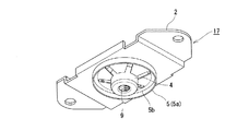
【選択図】 図2PROBLEM TO BE SOLVED: To provide a floating nut and a bolt which can be moved only in a required amount accurately without causing the nut or bolt to move carelessly in a plane direction.
A shaft portion 4 is projected from the center of a second plate 3 and penetrates through an opening 1 of the first plate 2 and is fastened by a fastener 5 made of a leaf spring. Then, the fastener 5 biases the shaft portion 4 outward in the axial direction.
[Selection] Figure 2
Description
本発明は、ケーシングの内部等に取付けて、そこにボルト等を介して各種部品を固定する際、そのナット等が水平方向に移動できるようにしたフローティングナットおよびフローティングボルトに関する。 The present invention relates to a floating nut and a floating bolt that are attached to the inside of a casing and the like, and when the various components are fixed thereto via bolts or the like, the nut and the like can be moved in the horizontal direction.
本出願人は、既に特許文献1に記載のフローティングナットを提案している。
このフローティングナットは、中央にネジ孔を有するナット板と、それを支持する支持板とを有し、その支持板の長手方向両端を折り返してナット板を抱持するものである。そしてナット板が平面に沿って移動可能としたものである。
The present applicant has already proposed the floating nut described in
This floating nut has a nut plate having a screw hole in the center and a support plate that supports the nut plate, and folds both ends in the longitudinal direction of the support plate to hold the nut plate. The nut plate is movable along a plane.
このフローティングナットは、金属板よりなる支持板の両端部を折り返して、内部にナット板を抱持し、そのナット板が平面方向に移動できるようにしたものである。
この種のフローティングナットは、それにボルトを締結する際、慎重に行わないと、ナット板にかかる外力により、支持板の折返し部を変形させてしまう。すると、その支持機能を失うことになる。
また、ボルトの不用意な操作により支持板の変形が大きいと、ナット板がケーシング内に脱落することも有り、ケーシングを解体してナット板を取り出さなければならない。
更に、支持板自体はケーシングにリベットやスポット溶接等で固着されているため、支持機能を失ったフローティングナットの付け替えに労力と時間を要する。
In this floating nut, both end portions of a support plate made of a metal plate are folded back so as to hold the nut plate therein so that the nut plate can be moved in the plane direction.
This type of floating nut deforms the folded portion of the support plate due to an external force applied to the nut plate unless the bolt is fastened to it. Then, the support function is lost.
Further, if the support plate is greatly deformed due to inadvertent operation of the bolt, the nut plate may fall into the casing, and the casing must be disassembled and the nut plate must be taken out.
Furthermore, since the support plate itself is fixed to the casing by rivets, spot welding or the like, labor and time are required to replace the floating nut that has lost its support function.
また、ナット板の移動のし易さは、ナット板を抱持する抱持力による。その抱持力の調整は、極めて厳密に行なう必要がある。通常は支持板のナット板の押さえ部分に僅かの凸面を形成しプレス圧力を調整することで行われる。強すぎればナット板の移動ができず、弱すぎればナット板が不用意に移動し、ボルトとの芯合わせができなくなる。その状態で、ボルトを締め付けるとフローティングナットのねじ部を損傷し、締め付けが困難乃至は不能となる場合がある。
特に、ケーシングの壁にフローティングナットを取り付けた場合には、ナット板の自重が作用するので移動のしやすさと保持力の兼ね合いは微妙な調整が必要となる。
この支持板によるナット板押さえ構造では、ナットの稼動範囲の大きさ、ナットサイズの違いおよび使用場所等により支持板のナット板押さえ部分の形状を変更しなければならないので、支持板の加工時のプレス型を変える必要があり製作にコストもかかる。
Further, the ease of movement of the nut plate depends on the holding force for holding the nut plate. It is necessary to adjust the holding force very strictly. Usually, it is performed by forming a slight convex surface in the pressing portion of the nut plate of the support plate and adjusting the press pressure. If it is too strong, the nut plate cannot be moved, and if it is too weak, the nut plate will move carelessly and the centering with the bolt will not be possible. If the bolt is tightened in this state, the threaded portion of the floating nut may be damaged, and tightening may be difficult or impossible.
In particular, when a floating nut is attached to the wall of the casing, the weight of the nut plate acts, so the balance between ease of movement and holding force needs to be finely adjusted.
In this nut plate holding structure with the support plate, the shape of the nut plate holding portion of the support plate must be changed according to the size of the operating range of the nut, the difference in the nut size and the place of use, etc. It is necessary to change the press mold, and the production is expensive.
そこで本発明は、ボルト締結の際に、不用意に支持板を変形することがなく且つ、ナットの抱持力を容易に且つ最適に調整することができる新たなフローティングナットおよびフローティングボルトを提供することを課題とする。 Therefore, the present invention provides a new floating nut and a floating bolt that can easily and optimally adjust the holding force of the nut without inadvertently deforming the support plate when fastening the bolt. This is the issue.
請求項1に記載の本発明は、開口(1)を有する第1プレート(2)と、
その第1プレート(2)の裏面に接して、その開口(1)を閉塞または横架する第2プレート(3)と、
その第2プレート(3)の中央に突設され、軸径が前記開口(1)より小で、その開口(1)を貫通する軸部(4)と、
その軸部(4)の軸線上に形成したネジ孔(9)と、
第1プレート(2)の表面に接し、前記開口(1)を閉塞または横架すると共に、前記軸部(4)の外周に被嵌されるファスナ(5)とを具備し、
前記ファスナ(5)は、板バネからなり、その中央に係止孔(6)を有すると共に、係止孔(6)の孔縁に複数の欠切部(8)が形成され、外周から係止孔(6)に向かい山形に形成されて、その外周が第1プレート(2) の表面に接すると共に、係止孔(6)が前記軸部(4)外周に被嵌されて軸方向外側にその軸部(4)を付勢することを特徴とするフローティングナットである。
The invention according to
A second plate (3) that is in contact with the back surface of the first plate (2) and closes or crosses the opening (1);
A shaft (4) projecting at the center of the second plate (3), having a shaft diameter smaller than the opening (1) and penetrating through the opening (1);
A screw hole (9) formed on the axis of the shaft (4);
The first plate (2) is in contact with the surface, the opening (1) is closed or horizontally mounted, and the fastener (5) is fitted on the outer periphery of the shaft portion (4).
The fastener (5) is made of a leaf spring, and has a locking hole (6) at the center thereof, and a plurality of notches (8) are formed at the hole edge of the locking hole (6), and is engaged from the outer periphery. It is formed in a mountain shape facing the stop hole (6), its outer periphery is in contact with the surface of the first plate (2), and the locking hole (6) is fitted on the outer periphery of the shaft part (4) to be axially outer A floating nut characterized by urging the shaft portion (4).
請求項2に記載の本発明は、開口(1)を有する第1プレート(2)と、
その第1プレート(2)の裏面に接して、その開口(1)を閉塞または横架する第2プレート(3)と、
その第2プレート(3)の中央に突設され、軸径が前記開口(1)より小で、前記開口(1)を貫通する軸部(4)と、
その軸部(4)の軸線上に形成したネジ孔(9)と、
第1プレート(2)の表面に裏面側が接し、前記開口(1)を閉塞または横架すると共に、前記軸部(4)が貫通する第3プレート(3a)と、
前記軸部(4)の外周の外ネジ(7)に螺着されて、第3プレート(3a)の表面側に接するナット(10)と、を具備し、
前記ナット(10)は、その軸部(4)を軸線方向の外側に付勢するように締結されることを特徴とするフローティングナットである。
The invention as claimed in
A second plate (3) that is in contact with the back surface of the first plate (2) and closes or crosses the opening (1);
A shaft (4) projecting at the center of the second plate (3), having a shaft diameter smaller than the opening (1) and penetrating through the opening (1);
A screw hole (9) formed on the axis of the shaft (4);
A third plate (3a) through which the back side is in contact with the front surface of the first plate (2), closes or horizontally covers the opening (1), and the shaft portion (4) penetrates;
A nut (10) screwed onto an outer screw (7) on the outer periphery of the shaft portion (4) and in contact with the surface side of the third plate (3a);
The nut (10) is a floating nut that is fastened so as to urge the shaft portion (4) outward in the axial direction.
請求項3に記載の本発明は、開口(1)を有する第1プレート(2)と、
その第1プレート(2)の裏面に接して、その開口(1)を閉塞または横架する第2プレート(3)と、
その第2プレート(3)の中央に突設され、軸径が前記開口(1)より小で、前記開口(1)を貫通する軸部(4)を有するボルト(4a)と、
第1プレート(2)の表面に接し、前記開口(1)を閉塞または横架すると共に、前記ボルト(4a)の外周に被嵌されるファスナ(5)とを具備し、
前記ファスナ(5)は、板バネからなり、その中央に係止孔(6)を有すると共に、係止孔(6)の孔縁に複数の欠切部(8)が形成され、外周から係止孔(6)に向かい山形に形成されて、その外周が第1プレート(2)の表面に接すると共に、係止孔(6)が前記ボルト(4a)の外周に被嵌されて軸方向外側にそのボルト(4a)を付勢することを特徴とするフローティングボルト
である。
The invention according to
A second plate (3) that is in contact with the back surface of the first plate (2) and closes or crosses the opening (1);
A bolt (4a) projecting at the center of the second plate (3), having a shaft diameter smaller than the opening (1) and having a shaft portion (4) passing through the opening (1);
The first plate (2) is in contact with the surface, the opening (1) is closed or horizontally mounted, and a fastener (5) is fitted on the outer periphery of the bolt (4a).
The fastener (5) is made of a leaf spring, and has a locking hole (6) at the center thereof, and a plurality of notches (8) are formed at the hole edge of the locking hole (6), and is engaged from the outer periphery. It is formed in a mountain shape facing the stop hole (6), its outer periphery is in contact with the surface of the first plate (2), and the locking hole (6) is fitted on the outer periphery of the bolt (4a) so as to be outside in the axial direction. This is a floating bolt characterized by energizing the bolt (4a).
請求項4に記載の本発明は、開口(1)を有する第1プレート(2)と、
その第1プレート(2) の裏面に接して、その開口(1)を閉塞または横架する第2プレート(3)と、
その第2プレート(3)の中央に突設され、軸径が前記開口(1)より小で、前記開口(1)を貫通する軸部(4)を有するボルト(4a)と、
第1プレート(2)の表面に裏面側が接し、前記開口(1)を閉塞または横架すると共に、前記ボルト(4a)が貫通する第3プレート(3a)と、
前記ボルト(4a)に螺着されて、第3プレート(3a)の表面側に接するナット(10)を具備し、
前記ナット(10)は、そのボルト(4a)を軸方向の外側に付勢するように締結されることを特徴とするフローティングボルトである。
The invention as claimed in
A second plate (3) that is in contact with the back surface of the first plate (2) and closes or horizontally covers the opening (1);
A bolt (4a) projecting at the center of the second plate (3), having a shaft diameter smaller than the opening (1) and having a shaft portion (4) passing through the opening (1);
A third plate (3a) through which the back surface is in contact with the front surface of the first plate (2), closes or horizontally covers the opening (1), and through which the bolt (4a) passes;
A nut (10) screwed to the bolt (4a) and in contact with the surface side of the third plate (3a);
The nut (10) is a floating bolt that is fastened so as to urge the bolt (4a) outward in the axial direction.
請求項5に記載の本発明は、請求項1〜請求項4のいずれかに記載のフローティングナットまたはフローティングボルトにおいて、
第1プレート(2)が台形に曲折されたフローティングナットまたはフローティングボルトである。
The present invention according to
The first plate (2) is a floating nut or a floating bolt bent into a trapezoid.
請求項6に記載の本発明は、
請求項1〜請求項5のいずれかに記載のフローティングナットまたはフローティングボルトにおいて、
前記ファスナ(5)は、円形の外周を有する板バネからなり、その中央に係止孔(6)を有すると共に、係止孔(6)の孔縁に放射状に複数の欠切部(8)が形成されたフローティングナットまたはフローティングボルトである。
The present invention according to
In the floating nut or the floating bolt according to any one of
The fastener (5) is made of a leaf spring having a circular outer periphery, and has a locking hole (6) in the center thereof, and a plurality of notches (8) radially at the hole edge of the locking hole (6). Is a floating nut or bolt formed.
請求項7に記載の本発明は、請求項1〜請求項5のいずれかに記載のフローティングナットまたはフローティングボルトにおいて、
前記ファスナ(5)は、方形の外周を有する板バネからなり、その中央に係止孔(6)を有すると共に、係止孔(6)の孔縁に互いに略平行な4本の欠切部(8)が形成され、
第1プレート(2)が台形に曲折され、その台形の頂部の両縁に、ファスナの可動範囲を規制するストッパ(20)が立ち上げられたフローティングナットまたはフローティングボルである。
The present invention according to
The fastener (5) is made of a leaf spring having a square outer periphery, and has a locking hole (6) at the center thereof, and four notch portions substantially parallel to the hole edge of the locking hole (6). (8) is formed,
It is a floating nut or a floating bolt in which a first plate (2) is bent into a trapezoid, and stoppers (20) for restricting the movable range of the fastener are raised on both edges of the top of the trapezoid.
請求項1に記載のフローティングナットは、板バネからなるファスナ5が第1プレート2の表面に接し、そのファスナ5が軸部4を軸方向外側に付勢するものである。
そのため、ボルトをフローティングナットに止着するときに加わる垂直な外力は、ファスナ5と第1プレート2で支持され、従来のように第1プレートの抱持部を変形することがない。
また、ボルトをフローティングナットに止着するとき、ファスナの付勢力により、軸部4が不用意に移動し過ぎることを防止し、その必要量の移動調整が容易で、フローティングナットにボルトを介して他の部品を確実に締結できる効果がある。また、上記の形状を有するファスナ5は汎用の量産品を使用できると共に、第1プレート2の形状を単純化でき、製造容易で安価にフローティングナットを提供できる。
In the floating nut according to the first aspect, the
Therefore, the vertical external force applied when the bolt is fastened to the floating nut is supported by the
In addition, when the bolt is fixed to the floating nut, the biasing force of the fastener prevents the
請求項2に記載のフローティングナットは、軸部4の外周にナット10が螺着されて、その軸部4を外側に付勢するものである。そのナット10の締結力の調整により、軸部4の付勢力を最適な値にできる。そのため、ボルトをフローティングナットに止着するとき、軸部4が不用意に移動し過ぎることを防止し、その必要量の移動調整が容易で、フローティングナットにボルトを介して他の部品を確実に締結できる効果がある。また、上記のナット10は汎用の量産品を使用できると共に、第1プレート2の形状を単純化でき、製造容易で安価なフローティングナットを提供できる。
さらには、ボルトをフローティングナットに止着するときに加わる垂直な外力は、ナット10と第1プレート2で支持され、従来のように第1プレートの抱持部を変形することがない。
In the floating nut according to the second aspect, the
Furthermore, the vertical external force applied when the bolt is fastened to the floating nut is supported by the
請求項3に記載のフローティングボルトは、板バネからなるファスナ5が第1プレート2の表面に接し、そのファスナ5の係止孔6がボルト4aを軸方向外側に付勢するものである。
そのため、ナット16をボルト4aに止着するとき、ファスナの付勢力により、ボルト4aが不用意に移動し過ぎることを防止し、その移動調整が容易なため、フローティングボルトにナット16を介して他の部品を確実に締結できる効果がある。また、上記の形状を有するファスナ5は汎用の量産品を使用できると共に、第1プレート2の形状を単純化でき、製造容易で安価なフローティングボルトを提供できる。
In the floating bolt according to the third aspect, the
Therefore, when fastening the
請求項4に記載のフローティングボルトは、ボルト4aの外周にナット10が螺着されて、そのボルト4aを外側に付勢するものである。そのナット10の締結力の調整により、ボルト4aの付勢力を最適な値にできる。そのため、別のナット16をフローティングボルトに止着するとき、ボルト4aの移動調整が容易で、フローティングボルトに別のナット16を介して他の部品を確実に締結できる効果がある。また、上記のナット10は汎用の量産品を使用できると共に、第1プレート2の形状を単純化でき、製造容易で安価なフローティングナットを提供できる。
According to a fourth aspect of the present invention, the
請求項5に記載のフローティングナットまたはボルトは、第1プレート2が台形に曲折されているため、第2プレート3を台形の内側に収納し、その状態でそれら全体を基板12等に取付けることができる。
In the floating nut or bolt according to
請求項6に記載のフローティングナットまたはボルトは、ファスナ(5)が、円形の外周を有する板バネからなり、その中央に係止孔(6)を有すると共に、係止孔(6)の孔縁に放射状に複数の欠切部(8)が形成されたから、ファスナ5のバネのバランスがよく、その軸部4が何れの方向にも円滑に移動できる。
In the floating nut or bolt according to
請求項7に記載のフローティングナットまたはボルトは、ファスナ(5)が、方形の外周を有する板バネからなり、その中央に係止孔(6)を有すると共に、係止孔(6)の孔縁に互いに略平行な4本の欠切部(8)が形成され、
第1プレート(2)が台形に曲折され、その台形の頂部の両縁に、ファスナの可動範囲を規制するストッパ(20)が立ち上げられたから、ファスナ5がストッパ20に規制された範囲のみを移動することができる。そのため、ファスナ5が他の隣接部品と干渉することかない。
The floating nut or bolt according to
Since the first plate (2) is bent into a trapezoid and the stoppers (20) that restrict the movable range of the fastener are raised on both edges of the top of the trapezoid, only the range where the
次に、図面に基づいて本発明の各実施の形態につき説明する。
図1〜図5は、本発明の第1実施例であり、請求項1に記載の発明である。
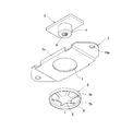
このフローティングナット17は、第1プレート2と第2プレート3とファスナ5とからなる。第1プレート2はその長手方向を断面ハット状に曲折し、その両端部に第1プレートの取付孔16aが穿設され、中央に開口1を穿設している。取付孔16aにはリベットやボルトが挿入され、基板12に取り付けられる。なお、取付孔16aを設けないで平面とし、スポット溶接等で基板12に取り付けてもよい。
また、幅方向両側には側部2aが曲折形成され、第1プレート2の剛性を高めると供に、第2プレート3の角部が第1プレートより突出するのを防止する。
Next, each embodiment of the present invention will be described with reference to the drawings.
1 to 5 show a first embodiment of the present invention, and the invention according to
The floating
In addition,
第2プレート3は、開口1の直径より大なる長辺を有し、短辺はそれよりも小に形成されている。そして、第2プレート3の中心に軸部4が固定されている。軸部4の軸線上には、ネジ孔9が設けられている。
なお、軸部4と第2プレート3とを別部品で形成し、図7の如くカシメ固定してそれを製造することができる。
或いは、第2プレート3と軸部4とを一体に成形してもよい。軸部4の直径は、開口1の直径よりも小である。
The
The
Or you may shape | mold the
次に、ファスナ5はその外直径が開口1より大であり、内歯付きの皿バネからなり、その底部5bの外周に筒部5aが僅かに立ち上げ形成され、底部5bの周縁部から中心に向って図4の如く傾斜して突出する皿状部を有し、その中心に図1の如く係止孔6が形成されている。係止孔6の直径は、軸部4の外直径よりも僅かに小である。そして係止孔6には、放射状に多数の欠切部8が欠切されている。
ファスナ5の底部5bの外周の筒部5aは必ずしも必要ではないが、ファスナ5の剛性を高めるためおよび軸部4にファスナ5を圧入するときの工具外周の位置決めとして有用である。
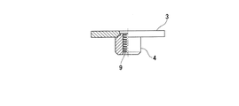
そして第2プレート3と軸部4とが一体化された状態で、第1プレート2の裏面側に第2プレート3を接触させ、軸部4を開口1に貫通させる。次いで、軸部4にファスナ5の係止孔6を圧入する。すると、図2及び図4に示す如く、ファスナ5の底部5bが第1プレート2の表面に圧接する。その圧接の接触抵抗は、ファスナ5を軸部4に圧入するときの圧入調整により行なう。
Next, the
The
Then, in a state where the
すると、軸部4はファスナ5の弾発力により第2プレートの軸部4を第2プレート3側と反対方向に付勢されることになる。すなわち、軸部4はファスナ5の弾発力により軸方向外側に付勢される。その付勢力を適宜な値になるようにファスナ5を軸部4に嵌着すればよい。すると、軸部4のネジ孔9にボルトを取付ける際、不用意に軸部4が平面方向に移動することなく、両者の軸線を合わせるに必要な移動量だけ軸部4を移動させることが可能となる。
そして一例として図4に示す如く、第1プレート2を基板12に適宜な方法で固定し、取付部材13を基板12にボルト14を介して締結固定することができる。このとき、軸部4は図において右方に移動し、取付部材13のボルト孔13aに整合される。それによりボルト14を軸部4のネジ孔9に締結して、取付部材13を基板12に固定することができる。
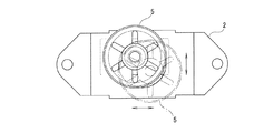
図5はそのファスナ5の移動範囲を示す説明図であり、同図において水平方向および垂直方向に移動させることができる。一例として、実線の状態から鎖線の状態にファスナ5を移動できる。
Then, the
As an example, as shown in FIG. 4, the
FIG. 5 is an explanatory view showing the movement range of the
次に、図6は本発明の第2実施例のフローティングナット17を示し、この例が図2のそれと異なる点は、第1プレート2の形状のみである。
この第1プレート2はカップ状に形成され、その開口端のフランジ部が基板12に適宜手段により固定されるものである。そして、取付部材13を基板12にボルト14を介して締結固定するものである。
このとき、フローティングナット17の軸部4が平面方向に移動し、軸線が整合される。
本実施例では、第1プレート2がカップ状に形成されているので、基板12に対して第1プレート2がスペーサの役目をし、しかもフローティングナットとしたので、取付部材13の締結固定が容易となる。
Next, FIG. 6 shows a floating
The
At this time, the
In the present embodiment, since the
次に、図8〜図11は夫々他の実施例を示し、これらが図3のそれと異なる点は、第2プレート3の形状または第1プレート2の開口1の形状である。
図8の例は、第2プレート3が正方形に形成され開口1を閉鎖するようにされている。
図9の例は、第2プレート3が三角形に形成され、その角部が開口1に横架(架橋)されている。
図10の例は、第1プレート2の開口1が第1プレート2の取付け方向と同方向の長手方向に細長いと共に、第2プレート3の長手方向がそれに直交するように架橋されている。
図11の例は、第1プレート2の開口1が第1プレート2の取付け方向と垂直方向の幅方向に細長く形成され、第2プレート3が第1プレート2の長手方向に架橋されている。
なお、図8〜図11は、第1プレート2の開口1と第2プレート3の形状関係について説明したが、本構成は同様に、第1プレート2の開口1とファスナ5の外周輪郭形状にも適用できる。
Next, FIG. 8 to FIG. 11 show other embodiments, respectively, which are different from those in FIG. 3 in the shape of the
In the example of FIG. 8, the
In the example of FIG. 9, the
In the example of FIG. 10, the
In the example of FIG. 11, the
8 to 11, the shape relationship between the
次に、図12は本発明のさらに他の実施例であり、軸部4と第2プレート3とが別部品からなる。
軸部4は、頭部15を一端に有し、その直径は第1プレート2の開口1よりも小である。そして第2プレート3に軸部4が貫通され、ファスナ5によりその軸部4が止着されるものである。
Next, FIG. 12 shows still another embodiment of the present invention, in which the
The
次に、図13は本発明のさらに他の実施例であり、本発明の請求項2に記載のものである。
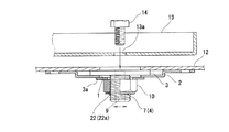
これは第2プレート3の中心に軸部4が突設され、その外周の外ネジ7にナット10が第3プレート3aを介して第1プレート2に適宜圧力で締結される。それにより、軸部4は軸線方向外側に付勢され、第2プレート3と第1プレート2との接触抵抗を適宜な値に保持するものである。なお、ナット10と第3プレート3aを一体に構成してもよい。
軸部4の中心にはネジ孔9が形成され、そのネジ孔9に取付部材13のボルト孔13aを介してボルト14が締結されるものである。このとき、第2プレート3および軸部4はボルト孔13aの軸線に整合するように平面方向に移動する。ナット10の締結力を適宜な値にすることにより、軸部4が不用意に移動することを防止し且つ、軸部4のネジ孔9とボルト孔13aとの位置合わせを容易にすることができる。
さらに、このナット10には、緩み止め板22が設けられ、それがナットのネジ孔周縁にかしめ固定されている。この緩み止め板22は、ナット10のネジ孔程度の内直径で、環状に形成され、その内周に部分的に爪部22aが突設され、それが軸部4の外ネジ7に係止される。それによって、ナット10が緩むことを防止している。
Next, FIG. 13 shows still another embodiment of the present invention, which is described in
The
A
Further, the
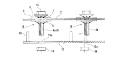
次に、図14は本発明のフローティングボルト18の第1実施例であり、請求項3に記載の発明である。これは第2プレート3の中心にボルト4aが固定されたものである。
この例では、第1プレート2に複数のフローティングボルト18が取付けられている。そして一例として、スタッド19を有する、取付部材13を第1プレート2に固定するとき、夫々のボルト4aにナット16を介して締結される。このとき同図において、右側のボルト4aが左方向に移動してボルト孔13aの軸線とボルト4aの軸線とが整合される。
FIG. 14 shows a first embodiment of the floating
In this example, a plurality of floating
次に、図15は本発明のフローティングボルト18の第2実施例である。この例が前記第1実施例と異なる点は、ボルト4aと第2プレート3とが別体であり、ボルト4aが頭部15を有するものである。そして、ボルト4aの付根に先ずファスナ5が嵌着され、次いでそれが第2プレート3及び第1プレート2の開口1を貫通する。次いでファスナ5がボルト4aの外周に嵌着されるものである。この例では、上下一対のファスナ5によって、ボルト4aが軸方向外側に付勢される。その付勢力を適宜に維持することにより、ボルト4aが平面方向に移動するとき不用意に、より大きく移動することを防止できる。
Next, FIG. 15 shows a second embodiment of the floating
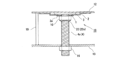
次に、図16は本発明のフローティングボルト18の第3実施例であり、これは請求項4に記載の発明に相当する。
このフローティングボルト18が、図14の実施例と異なる点は、ファスナ5の変わりにナット10を用いたものである。そしてそのナット10を第3プレート3aを介して、第2プレート3に適宜圧力で締結する。それにより、ボルト4aを軸線方向外方に付勢し、それが平面方向に不用意に移動することを防止すると共に、必要量だけ平面方向に移動させることが容易となる。なお、ナット10と第3プレート3aを一体に構成してもよい。この例も、前記図13の例と同様に、ナット10に緩み止め板22が設けられ、その爪部22aが軸部4の外ネジに係止され、緩み止めを行なう。
Next, FIG. 16 shows a third embodiment of the floating
The floating
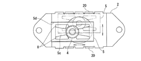
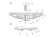
次に、図17は本発明のさらに他のフローティングナットの分解斜視図であり、この例が図1の実施例と異なる点は、ファスナ5の形状および第1プレート2にストッパ20を設けた点である。このファスナ5は、方形の外周を有する板ばねからなり、その長辺側両側に補強壁5dが立ち上げられ、係止孔6の回りに互いに離間して設けた欠切部8がほぼ互いに平行に形成されている(図19参照)。また、第1プレート2には、ファスナ5側に複数のストッパ20がその両側に立上げられている。さらに、軸部4には環状溝21が設けられ、そこにファスナ5の変形部5cの先端が係止される。
Next, FIG. 17 is an exploded perspective view of still another floating nut of the present invention. This example is different from the embodiment of FIG. 1 in that the shape of the
このファスナ5の変形部5cは図18(B)のごとく、自由状態で軸線方向外側に突出した状態から、取付時にその変形部5cを軸線方向内側へ押込むことにより、その先端を環状溝21に係止する。即ち、変形部5cはファスナ5を取り付ける際、図18(B)の、実線の状態から鎖線の状態に移動する。
そして係止されると、変形部5cはもとの自由状態に戻る付勢力が働き、軸部4を軸線方向外側に付勢する。
次に、ファスナ5は図19に示すごとく、その補強壁5dがストッパ20に当接するまで移動が可能である。このストッパ20によって、ファスナ5の一部が第1プレート2から外側に飛び出すことがない。それにより、フローティングナットに隣接する部品とファスナ5とが干渉することを防止できる。
As shown in FIG. 18 (B), the
When locked, the deforming
Next, as shown in FIG. 19, the
次に、図20は本発明のさらに他の実施例であり、この例が図18の実施例と異なる点は、ファスナ5の変形部5cの自由状態における形状のみである。この変形部5cは自由状態において、同図(B)の実線のごとくその底部5bに平行である。そして、取付時においては実線の状態から鎖線の状態に押込まれ、その反作用として軸部4を軸方向外方に付勢する。
Next, FIG. 20 shows still another embodiment of the present invention, and this example is different from the embodiment of FIG. 18 only in the shape of the
図17〜図20に示す実施例のフローティングナットは、基板12の縁部にフローティングナットを取り付ける場合に有用である。すなわち、第1実施例のような外周円形のファスナ5を用いた場合、図5に示すように第1プレート2よりファスナ5が飛び出すことがある。
すると、これを基板12の縁部に使用すると、基板12よりファスナ5の一部分が飛び出すことになり、他の基板類の取り付けに支障をきたしたり、ファスナ5の飛び出し部が損傷を受けたりする不具合が生ずるおそれがある。
また、基板12の縁部が折り曲げられて壁状になっている場合は、フローティングナットの稼動範囲を制限することとなる。
The floating nut of the embodiment shown in FIGS. 17 to 20 is useful when the floating nut is attached to the edge of the
Then, if this is used at the edge of the
In addition, when the edge of the
本実施例においては、ファスナ5の外周を方形にすることにより、基板12の縁部であってもファスナ5が第1プレート2より飛び出すことがなく、しかも第1プレート2の開口1に沿ったフローティング範囲を確保できる。
更に、ストッパ20を設けることで、第2プレート3が図1に示すような方形であると、ファスナ5の方形を第1プレート2に取り付けるときに方向を合わせる必要がなく、任意の位置で組み付け可能である。
すなわち、第2プレート3とファスナ5がクロスした状態で組みつけられても、ストッパ20によって制限されるので第1プレート2よりファスナ5の角部が飛び出すことがない。
In the present embodiment, the outer periphery of the
Furthermore, if the
That is, even if the
1 開口
2 第1プレート
2a 補強壁
3 第2プレート
3a 第3プレート
4 軸部
4a ボルト
5 ファスナ
5a 筒部
5b 底部
5c 変形部
5d 補強壁
1 opening 2 first plate
5a Tube
5b bottom
5c Deformation part
5d reinforcement wall
6 係止孔
7 外ネジ
8 欠切部
9 ネジ孔
10 ナット
12 基板
13 取付部材
13a ボルト孔
14 ボルト
6 Locking
10 nuts
12 Board
13 Mounting member
13a Bolt hole
14 volts
15 頭部
16 ナット
16a 取付孔
17 フローティングナット
18 フローティングボルト
19 スタッド
20 ストッパ
21 環状溝
22 緩み止め板
22a 爪部
15 heads
16 nuts
16a Mounting hole
17 Floating nut
18 Floating bolt
19 Stud
20 Stopper
21 annular groove
22 Locking plate
22a Claw
Claims (7)
その第1プレート(2)の裏面に接して、その開口(1)を閉塞または横架する第2プレート(3)と、
その第2プレート(3)の中央に突設され、軸径が前記開口(1)より小で、その開口(1)を貫通する軸部(4)と、
その軸部(4)の軸線上に形成したネジ孔(9)と、
第1プレート(2)の表面に接し、前記開口(1)を閉塞または横架すると共に、前記軸部(4)の外周に被嵌されるファスナ(5)とを具備し、
前記ファスナ(5)は、板バネからなり、その中央に係止孔(6)を有すると共に、係止孔(6)の孔縁に複数の欠切部(8)が形成され、外周から係止孔(6)に向かい山形に形成されて、その外周が第1プレート(2) の表面に接すると共に、係止孔(6)が前記軸部(4)外周に被嵌されて軸方向外側にその軸部(4)を付勢することを特徴とするフローティングナット。 A first plate (2) having an opening (1);
A second plate (3) that is in contact with the back surface of the first plate (2) and closes or crosses the opening (1);
A shaft (4) projecting at the center of the second plate (3), having a shaft diameter smaller than the opening (1) and penetrating through the opening (1);
A screw hole (9) formed on the axis of the shaft (4);
The first plate (2) is in contact with the surface, the opening (1) is closed or horizontally mounted, and the fastener (5) is fitted on the outer periphery of the shaft portion (4).
The fastener (5) is made of a leaf spring, and has a locking hole (6) at the center thereof, and a plurality of notches (8) are formed at the hole edge of the locking hole (6), and is engaged from the outer periphery. It is formed in a mountain shape facing the stop hole (6), its outer periphery is in contact with the surface of the first plate (2), and the locking hole (6) is fitted on the outer periphery of the shaft part (4) to be axially outer Floating nut characterized by urging the shaft (4).
その第1プレート(2)の裏面に接して、その開口(1)を閉塞または横架する第2プレート(3)と、
その第2プレート(3)の中央に突設され、軸径が前記開口(1)より小で、前記開口(1)を貫通する軸部(4)と、
その軸部(4)の軸線上に形成したネジ孔(9)と、
第1プレート(2)の表面に裏面側が接し、前記開口(1)を閉塞または横架すると共に、前記軸部(4)が貫通する第3プレート(3a)と、
前記軸部(4)の外周の外ネジ(7)に螺着されて、第3プレート(3a)の表面側に接するナット(10)と、を具備し、
前記ナット(10)は、その軸部(4)を軸線方向の外側に付勢するように締結されることを特徴とするフローティングナット。 A first plate (2) having an opening (1);
A second plate (3) that is in contact with the back surface of the first plate (2) and closes or crosses the opening (1);
A shaft (4) projecting at the center of the second plate (3), having a shaft diameter smaller than the opening (1) and penetrating through the opening (1);
A screw hole (9) formed on the axis of the shaft (4);
A third plate (3a) through which the back side is in contact with the front surface of the first plate (2), closes or horizontally covers the opening (1), and the shaft portion (4) penetrates;
A nut (10) screwed onto an outer screw (7) on the outer periphery of the shaft portion (4) and in contact with the surface side of the third plate (3a);
The nut (10) is fastened so as to urge the shaft (4) outward in the axial direction.
その第1プレート(2)の裏面に接して、その開口(1)を閉塞または横架する第2プレート(3)と、
その第2プレート(3)の中央に突設され、軸径が前記開口(1)より小で、前記開口(1)を貫通する軸部(4)を有するボルト(4a)と、
第1プレート(2)の表面に接し、前記開口(1)を閉塞または横架すると共に、前記ボルト(4a)の外周に被嵌されるファスナ(5)とを具備し、
前記ファスナ(5)は、板バネからなり、その中央に係止孔(6)を有すると共に、係止孔(6)の孔縁に複数の欠切部(8)が形成され、外周から係止孔(6)に向かい山形に形成されて、その外周が第1プレート(2)の表面に接すると共に、係止孔(6)が前記ボルト(4a)の外周に被嵌されて軸方向外側にそのボルト(4a)を付勢することを特徴とするフローティングボルト。 A first plate (2) having an opening (1);
A second plate (3) that is in contact with the back surface of the first plate (2) and closes or crosses the opening (1);
A bolt (4a) projecting at the center of the second plate (3), having a shaft diameter smaller than the opening (1) and having a shaft portion (4) passing through the opening (1);
The first plate (2) is in contact with the surface, the opening (1) is closed or horizontally mounted, and a fastener (5) is fitted on the outer periphery of the bolt (4a).
The fastener (5) is made of a leaf spring, and has a locking hole (6) at the center thereof, and a plurality of notches (8) are formed at the hole edge of the locking hole (6), and is engaged from the outer periphery. It is formed in a mountain shape facing the stop hole (6), its outer periphery is in contact with the surface of the first plate (2), and the locking hole (6) is fitted on the outer periphery of the bolt (4a) so as to be outside in the axial direction. Floating bolt characterized by energizing the bolt (4a).
その第1プレート(2) の裏面に接して、その開口(1)を閉塞または横架する第2プレート(3)と、
その第2プレート(3)の中央に突設され、軸径が前記開口(1)より小で、前記開口(1)を貫通する軸部(4)を有するボルト(4a)と、
第1プレート(2)の表面に裏面側が接し、前記開口(1)を閉塞または横架すると共に、前記ボルト(4a)が貫通する第3プレート(3a)と、
前記ボルト(4a)に螺着されて、第3プレート(3a)の表面側に接するナット(10)を具備し、
前記ナット(10)は、そのボルト(4a)を軸方向の外側に付勢するように締結されることを特徴とするフローティングボルト。 A first plate (2) having an opening (1);
A second plate (3) that is in contact with the back surface of the first plate (2) and closes or horizontally covers the opening (1);
A bolt (4a) projecting at the center of the second plate (3), having a shaft diameter smaller than the opening (1) and having a shaft portion (4) passing through the opening (1);
A third plate (3a) through which the back surface is in contact with the front surface of the first plate (2), closes or horizontally covers the opening (1), and through which the bolt (4a) passes;
A nut (10) screwed to the bolt (4a) and in contact with the surface side of the third plate (3a);
The nut (10) is fastened so as to urge the bolt (4a) outward in the axial direction.
第1プレート(2)が台形に曲折されたフローティングナットまたはフローティングボルト。 In the floating nut or the floating bolt according to any one of claims 1 to 4,
A floating nut or floating bolt in which the first plate (2) is bent into a trapezoid.
前記ファスナ(5)は、円形の外周を有する板バネからなり、その中央に係止孔(6)を有すると共に、係止孔(6)の孔縁に放射状に複数の欠切部(8)が形成されたフローティングナットまたはフローティングボルト。 In the floating nut or the floating bolt according to any one of claims 1 to 5,
The fastener (5) is made of a leaf spring having a circular outer periphery, and has a locking hole (6) in the center thereof, and a plurality of notches (8) radially at the hole edge of the locking hole (6). Formed with floating nuts or floating bolts.
前記ファスナ(5)は、方形の外周を有する板バネからなり、その中央に係止孔(6)を有すると共に、係止孔(6)の孔縁に互いに略平行な4本の欠切部(8)が形成され、
第1プレート(2)が台形に曲折され、その台形の頂部の両縁に、ファスナ(5)の可動範囲を規制するストッパ(20)が立ち上げられたフローティングナットまたはフローティングボルト。 In the floating nut or the floating bolt according to any one of claims 1 to 5,
The fastener (5) is made of a leaf spring having a square outer periphery, and has a locking hole (6) at the center thereof, and four notch portions substantially parallel to the hole edge of the locking hole (6). (8) is formed,
A floating nut or bolt in which the first plate (2) is bent into a trapezoid, and stoppers (20) for restricting the movable range of the fastener (5) are raised on both edges of the top of the trapezoid.
Priority Applications (1)
| Application Number | Priority Date | Filing Date | Title |
|---|---|---|---|
| JP2012137618A JP6096429B2 (en) | 2012-06-19 | 2012-06-19 | Floating nut and floating bolt |
Applications Claiming Priority (1)
| Application Number | Priority Date | Filing Date | Title |
|---|---|---|---|
| JP2012137618A JP6096429B2 (en) | 2012-06-19 | 2012-06-19 | Floating nut and floating bolt |
Publications (2)
| Publication Number | Publication Date |
|---|---|
| JP2014001802A true JP2014001802A (en) | 2014-01-09 |
| JP6096429B2 JP6096429B2 (en) | 2017-03-15 |
Family
ID=50035166
Family Applications (1)
| Application Number | Title | Priority Date | Filing Date |
|---|---|---|---|
| JP2012137618A Active JP6096429B2 (en) | 2012-06-19 | 2012-06-19 | Floating nut and floating bolt |
Country Status (1)
| Country | Link |
|---|---|
| JP (1) | JP6096429B2 (en) |
Cited By (4)
| Publication number | Priority date | Publication date | Assignee | Title |
|---|---|---|---|---|
| JP2018091466A (en) * | 2016-12-07 | 2018-06-14 | Necプラットフォームズ株式会社 | Piece member attachment structure and rack |
| CN110155252A (en) * | 2019-05-07 | 2019-08-23 | 巢湖市银环航标有限公司 | a navigation light buoy |
| CN115467888A (en) * | 2022-10-11 | 2022-12-13 | 东风(武汉)汽车零部件有限公司 | A floating nut structure and its installation and use method |
| CN116601397A (en) * | 2021-09-28 | 2023-08-15 | 宁德时代新能源科技股份有限公司 | Floating nut assembly and electrical equipment |
Citations (12)
| Publication number | Priority date | Publication date | Assignee | Title |
|---|---|---|---|---|
| JPS53149166U (en) * | 1977-04-28 | 1978-11-24 | ||
| JPS57182623U (en) * | 1981-05-07 | 1982-11-19 | ||
| JPS60169416U (en) * | 1984-04-02 | 1985-11-09 | 株式会社イナックス | Fixtures for mounting equipment |
| JPH0359510U (en) * | 1989-10-16 | 1991-06-12 | ||
| JPH0448410U (en) * | 1990-08-30 | 1992-04-24 | ||
| JPH058020U (en) * | 1991-07-16 | 1993-02-02 | 三菱自動車工業株式会社 | Clip |
| JPH0642518A (en) * | 1992-05-26 | 1994-02-15 | Misawa Homes Co Ltd | Nut |
| JP2000046026A (en) * | 1998-07-24 | 2000-02-15 | Tennex Corp | Parts fastening structure with push nut |
| JP2001278110A (en) * | 2000-03-31 | 2001-10-10 | Isuzu Motors Ltd | Cage nut |
| JP2003053844A (en) * | 2001-08-17 | 2003-02-26 | Kyoichi Murata | Press-fit fixing structure between synthetic resin member and sheet metal member |
| JP2005083460A (en) * | 2003-09-08 | 2005-03-31 | Ochiai:Kk | clip |
| JP2011140978A (en) * | 2010-01-06 | 2011-07-21 | Takigen Mfg Co Ltd | Floating nut |
-
2012
- 2012-06-19 JP JP2012137618A patent/JP6096429B2/en active Active
Patent Citations (12)
| Publication number | Priority date | Publication date | Assignee | Title |
|---|---|---|---|---|
| JPS53149166U (en) * | 1977-04-28 | 1978-11-24 | ||
| JPS57182623U (en) * | 1981-05-07 | 1982-11-19 | ||
| JPS60169416U (en) * | 1984-04-02 | 1985-11-09 | 株式会社イナックス | Fixtures for mounting equipment |
| JPH0359510U (en) * | 1989-10-16 | 1991-06-12 | ||
| JPH0448410U (en) * | 1990-08-30 | 1992-04-24 | ||
| JPH058020U (en) * | 1991-07-16 | 1993-02-02 | 三菱自動車工業株式会社 | Clip |
| JPH0642518A (en) * | 1992-05-26 | 1994-02-15 | Misawa Homes Co Ltd | Nut |
| JP2000046026A (en) * | 1998-07-24 | 2000-02-15 | Tennex Corp | Parts fastening structure with push nut |
| JP2001278110A (en) * | 2000-03-31 | 2001-10-10 | Isuzu Motors Ltd | Cage nut |
| JP2003053844A (en) * | 2001-08-17 | 2003-02-26 | Kyoichi Murata | Press-fit fixing structure between synthetic resin member and sheet metal member |
| JP2005083460A (en) * | 2003-09-08 | 2005-03-31 | Ochiai:Kk | clip |
| JP2011140978A (en) * | 2010-01-06 | 2011-07-21 | Takigen Mfg Co Ltd | Floating nut |
Cited By (5)
| Publication number | Priority date | Publication date | Assignee | Title |
|---|---|---|---|---|
| JP2018091466A (en) * | 2016-12-07 | 2018-06-14 | Necプラットフォームズ株式会社 | Piece member attachment structure and rack |
| CN110155252A (en) * | 2019-05-07 | 2019-08-23 | 巢湖市银环航标有限公司 | a navigation light buoy |
| CN116601397A (en) * | 2021-09-28 | 2023-08-15 | 宁德时代新能源科技股份有限公司 | Floating nut assembly and electrical equipment |
| CN115467888A (en) * | 2022-10-11 | 2022-12-13 | 东风(武汉)汽车零部件有限公司 | A floating nut structure and its installation and use method |
| CN115467888B (en) * | 2022-10-11 | 2025-09-26 | 东实(武汉)汽车零部件有限公司 | A floating nut structure and its installation and use method |
Also Published As
| Publication number | Publication date |
|---|---|
| JP6096429B2 (en) | 2017-03-15 |
Similar Documents
| Publication | Publication Date | Title |
|---|---|---|
| US8899894B2 (en) | Device for fasting a component to a fastening stud | |
| US8292562B2 (en) | Fastener and fixing device and electronic device using the same | |
| US9982700B2 (en) | Fastener | |
| US8066465B2 (en) | Fastening device with tolerance compensation | |
| JPH0315847Y2 (en) | ||
| CN101981329B (en) | clip | |
| JP4954314B2 (en) | Flange fastening structure | |
| JP5432009B2 (en) | clip | |
| JP6096429B2 (en) | Floating nut and floating bolt | |
| JP5839739B2 (en) | Clip and member mounting structure including the clip | |
| JP7638155B2 (en) | Plate-like member connection structure | |
| US11566649B2 (en) | Spacer assembly | |
| JPH0557448B2 (en) | ||
| JP2009270615A (en) | Clip | |
| JP6096521B2 (en) | Floating nut and floating bolt | |
| JP5632941B1 (en) | Fastener mounting device and fastener mounting structure | |
| JP2013104494A (en) | Thin plate fixing structure | |
| RU177865U1 (en) | STRUCTURE ASSEMBLY ASSEMBLY SPEAKER OR AMPLIFIER | |
| CN114258274B (en) | System for fastening furniture legs to furniture and method of fastening furniture legs to furniture | |
| KR101806573B1 (en) | Nob and Lever Assembly | |
| KR20190068208A (en) | Fastening devices for preventing nut from loosening | |
| KR101514888B1 (en) | A bracket for absorbing tolerance | |
| JP4698408B2 (en) | Leg adjustment mechanism and electronic device | |
| EP2721325B1 (en) | Attachment assembly | |
| EP3273097A1 (en) | Power transmission device |
Legal Events
| Date | Code | Title | Description |
|---|---|---|---|
| A621 | Written request for application examination |
Free format text: JAPANESE INTERMEDIATE CODE: A621 Effective date: 20150514 |
|
| A977 | Report on retrieval |
Free format text: JAPANESE INTERMEDIATE CODE: A971007 Effective date: 20160205 |
|
| A131 | Notification of reasons for refusal |
Free format text: JAPANESE INTERMEDIATE CODE: A131 Effective date: 20160329 |
|
| A521 | Request for written amendment filed |
Free format text: JAPANESE INTERMEDIATE CODE: A523 Effective date: 20160530 |
|
| A131 | Notification of reasons for refusal |
Free format text: JAPANESE INTERMEDIATE CODE: A131 Effective date: 20161101 |
|
| A521 | Request for written amendment filed |
Free format text: JAPANESE INTERMEDIATE CODE: A523 Effective date: 20161220 |
|
| TRDD | Decision of grant or rejection written | ||
| A01 | Written decision to grant a patent or to grant a registration (utility model) |
Free format text: JAPANESE INTERMEDIATE CODE: A01 Effective date: 20170214 |
|
| A61 | First payment of annual fees (during grant procedure) |
Free format text: JAPANESE INTERMEDIATE CODE: A61 Effective date: 20170216 |
|
| R150 | Certificate of patent or registration of utility model |
Ref document number: 6096429 Country of ref document: JP Free format text: JAPANESE INTERMEDIATE CODE: R150 |