JP2014005176A - Severing device - Google Patents

Severing device Download PDF

Info

Publication number
JP2014005176A
JP2014005176A JP2012142417A JP2012142417A JP2014005176A JP 2014005176 A JP2014005176 A JP 2014005176A JP 2012142417 A JP2012142417 A JP 2012142417A JP 2012142417 A JP2012142417 A JP 2012142417A JP 2014005176 A JP2014005176 A JP 2014005176A
Authority
JP
Japan
Prior art keywords
glass sheet
pair
sandwiching
support bar
clamping
Prior art date
Legal status (The legal status is an assumption and is not a legal conclusion. Google has not performed a legal analysis and makes no representation as to the accuracy of the status listed.)
Pending
Application number
JP2012142417A
Other languages
Japanese (ja)
Inventor
Gunpei Yokoyama
群平 横山
Tsuneo Nakai
恒夫 中井
Current Assignee (The listed assignees may be inaccurate. Google has not performed a legal analysis and makes no representation or warranty as to the accuracy of the list.)
GY SYSTEMS CO Ltd
Original Assignee
GY SYSTEMS CO Ltd
Priority date (The priority date is an assumption and is not a legal conclusion. Google has not performed a legal analysis and makes no representation as to the accuracy of the date listed.)
Filing date
Publication date
Application filed by GY SYSTEMS CO Ltd filed Critical GY SYSTEMS CO Ltd
Priority to JP2012142417A priority Critical patent/JP2014005176A/en
Priority to TW102122336A priority patent/TW201408609A/en
Priority to PCT/JP2013/068189 priority patent/WO2014003198A1/en
Priority to CN201380030475.9A priority patent/CN104603072A/en
Publication of JP2014005176A publication Critical patent/JP2014005176A/en
Pending legal-status Critical Current

Links

Images

Classifications

    • CCHEMISTRY; METALLURGY
    • C03GLASS; MINERAL OR SLAG WOOL
    • C03BMANUFACTURE, SHAPING, OR SUPPLEMENTARY PROCESSES
    • C03B33/00Severing cooled glass
    • C03B33/02Cutting or splitting sheet glass or ribbons; Apparatus or machines therefor
    • C03B33/0215Cutting or splitting sheet glass or ribbons; Apparatus or machines therefor the ribbon being in a substantially vertical plane

Landscapes

  • Chemical & Material Sciences (AREA)
  • Engineering & Computer Science (AREA)
  • Materials Engineering (AREA)
  • Organic Chemistry (AREA)
  • Re-Forming, After-Treatment, Cutting And Transporting Of Glass Products (AREA)
  • Perforating, Stamping-Out Or Severing By Means Other Than Cutting (AREA)

Abstract

PROBLEM TO BE SOLVED: To provide a severing device capable of precisely dividing a glass sheet, which is moving, into a plurality of glass plates without requiring a wide installation space and without using a robot providing cause of raising facility costs.SOLUTION: There is provided the severing device that manufactures glass plates of predetermined size by dividing a glass sheet, which continuously moves and in which mark-off lines is already given, along the mark-off lines. The severing device includes: a support bar which extends in a direction crossing one direction and can be supported on one surface of the glass sheet that is moving; a holding device configured to hold the glass sheet having passed over the support bar; and a driving device for rotation, which rotates the holding device to one surface side of the glass sheet around a shaft center extending in the same direction as that of the support bar while the holding device holds the glass sheet and the mark-off line of the glass sheet is aligned with the support bar.

Description

本発明は、ガラスシートを分割してガラス板を作製する折割装置に関する。   The present invention relates to a folding apparatus that divides a glass sheet to produce a glass plate.

従来から、ガラスシートから所定サイズのガラス板を作製する装置として、ガラスシートに施された罫書線に沿って該ガラスシートを分断する折割装置が提供されている。そして、この種の折割装置には、一方向に連続的に進行するガラスシートを進行方向で順々に分割し、複数枚のガラス板を連続的に作製するようにしたものがある。   2. Description of the Related Art Conventionally, as an apparatus for producing a glass sheet of a predetermined size from a glass sheet, a folding apparatus that divides the glass sheet along a ruled line applied to the glass sheet is provided. In this type of folding apparatus, there is one in which a glass sheet that continuously proceeds in one direction is divided in order in the direction of travel to continuously produce a plurality of glass plates.

かかる折割装置は、ガラスシートの進行方向と直交する方向に延び、進行中のガラスシートの一方の面を支持可能な支持バーと、ガラスシートを保持可能に構成された保持装置と、保持装置を移送する移送装置とを備える。この種の折割装置は、移送装置がガラスシートを保持した保持手段を移送することで、ガラスシートを罫書線に沿って分割するようになっている。   Such a folding device includes a support bar that extends in a direction orthogonal to the traveling direction of the glass sheet and can support one surface of the ongoing glass sheet, a holding device configured to hold the glass sheet, and a holding device. And a transfer device for transferring. In this type of folding device, the transfer device transfers the holding means holding the glass sheet, so that the glass sheet is divided along the ruled lines.

そして、この種の折割装置の移送装置には、ロボットが採用されることがある。ロボットは、傾動可能な少なくとも一つのアームを有し、アームの最先端に保持装置が連結される。かかるロボットは、アームを適宜傾動させることで、支持バーの下流側に到達したガラスシートを保持可能な位置に保持装置を移送し、ガラスシート上の罫書線と支持バーとが一致した状態になると、ガラスシート上の罫書線と一致する位置を中心とする回転軌道を通るように、ガラスシートを保持した保持装置を、ガラスシートの一方の面側(支持バーの存在する側)に移送する。   A robot may be employed as a transfer device for this type of folding device. The robot has at least one arm that can be tilted, and a holding device is coupled to the tip of the arm. Such a robot moves the holding device to a position where the glass sheet that has reached the downstream side of the support bar can be held by appropriately tilting the arm, and when the ruled line on the glass sheet and the support bar coincide with each other. Then, the holding device holding the glass sheet is transferred to one surface side of the glass sheet (side where the support bar exists) so as to pass through a rotating track centering on a position coincident with the ruled line on the glass sheet.

これにより、この種の折割装置は、保持機構の移送(回転)に伴い、罫書線と一致する位置を中心とした回転モーメントをガラスシートに作用させ、ガラスシートを罫書線に沿って分割するようになっている(例えば、特許文献1参照)。   As a result, this type of folding device causes the rotation moment about the position coincident with the ruled line to act on the glass sheet as the holding mechanism is transferred (rotated), and divides the glass sheet along the ruled line. (For example, refer to Patent Document 1).

特表2008−511522号公報Special table 2008-511522 gazette

ところで、保持装置を移送する移送装置にロボットを採用すると、保持装置を適正なタイミングで移送でき、ガラスシートを精度よく分割することができる。しかしながら、ロボットは、高価なものであり、折割装置を設備するに当たり、コストを高騰させてしまう。   By the way, when a robot is adopted as a transfer device for transferring the holding device, the holding device can be transferred at an appropriate timing, and the glass sheet can be divided with high accuracy. However, the robot is expensive, and increases the cost when installing the splitting device.

また、従来の折割装置は、ロボットのアームが傾動(旋回)することで保持装置(ガラスシート)を移送するため、当該折割装置を設備するに当たり、アームの稼動範囲を含めた広いスペースが必要である。   In addition, since the conventional folding device transfers the holding device (glass sheet) by tilting (turning) the arm of the robot, a large space including the operating range of the arm is required for installing the folding device. is necessary.

そこで、本発明は、斯かる実情に鑑み、広い設置スペースを必要とし、また、設備コストの高騰の原因となるロボットを用いることなく、進行中のガラスシートから複数のガラス板を精度よく分割することのできる折割装置を提供することを課題とする。   Therefore, in view of such circumstances, the present invention requires a large installation space and accurately divides a plurality of glass plates from an ongoing glass sheet without using a robot that causes an increase in equipment cost. It is an object of the present invention to provide a folding device that can be used.

本発明に係る折割装置は、一方向に連続的に進行するガラスシートであって、前記一方向と交差する方向に延びる罫書線が予め施されたガラスシートを前記罫書線に沿って分割し、前記ガラスシートから所定サイズのガラス板を作製する折割装置であって、前記一方向と交差する方向に延び、進行中のガラスシートの一方の面を支持可能な支持バーと、該支持バー上を通過した前記ガラスシートを挟持可能に構成された挟持装置と、該挟持装置が前記ガラスシートを挟持し、且つ前記ガラスシートの前記罫書線が前記支持バーと一致した状態で、前記支持バーと同方向に延びる軸心回りで前記ガラスシートの一方の面側に前記挟持装置を回転させる回転用駆動装置と、を備えることを特徴とする。   The folding device according to the present invention is a glass sheet that continuously proceeds in one direction, and divides a glass sheet preliminarily provided with a ruled line extending in a direction intersecting the one direction along the ruled line. A folding device for producing a glass plate of a predetermined size from the glass sheet, the support bar extending in a direction crossing the one direction and capable of supporting one surface of the ongoing glass sheet, and the support bar A holding device configured to be able to hold the glass sheet that has passed above, and the support bar in a state where the holding device holds the glass sheet and the ruled line of the glass sheet coincides with the support bar. And a rotation driving device for rotating the clamping device on one surface side of the glass sheet around an axis extending in the same direction as the rotation direction of the glass sheet.

上記構成によれば、回転用駆動装置がガラスシートを挟持した挟持装置を回転させることで、挟持装置に挟持されたガラスシートも支持バーと同方向に延びる軸心(挟持装置の回転中心)回りで回転しようとする。そのため、ガラスシートが回転しようとすると、該ガラスシートには、支持バーを支点とする曲げモーメントが作用する。従って、ガラスシートの罫書線と支持バーとが一致した状態で、ガラスシートに曲げモーメントを作用させることで、ガラスシートの罫書線上に曲げ応力が集中し、ガラスシートが罫書線に沿って分割される。これにより、挟持装置に挟持されたガラスシート(分割されたガラスシート)が所定サイズのガラス板となる。そして、挟持装置によるガラス板の挟持が解除されることで、ガラス板の取り出しや移送が可能になる。   According to the above configuration, the rotation driving device rotates the clamping device that sandwiches the glass sheet, so that the glass sheet sandwiched by the sandwiching device also rotates around the axis (rotation center of the sandwiching device) extending in the same direction as the support bar. Try to rotate with. Therefore, when the glass sheet tries to rotate, a bending moment about the support bar acts on the glass sheet. Therefore, by applying a bending moment to the glass sheet with the ruled line of the glass sheet and the support bar aligned, the bending stress is concentrated on the ruled line of the glass sheet, and the glass sheet is divided along the ruled line. The Thereby, the glass sheet (divided glass sheet) clamped by the clamping apparatus becomes a glass plate of a predetermined size. Then, by releasing the holding of the glass plate by the holding device, the glass plate can be taken out and transferred.

このように、上記構成の折割装置は、ロボットと比較して構成や制御が簡易でありながらもガラスシートを所定サイズのガラス板に確実に分割することができる。そして、折割装置は、構成や制御が複雑でない上に動作範囲が狭いため、設備コストを抑えることができるとともに、狭いスペースでも設置することができる。   As described above, the folding device having the above configuration can reliably divide a glass sheet into glass plates of a predetermined size while being simple in configuration and control as compared with a robot. The folding device is not complicated in configuration and control and has a narrow operation range, so that the equipment cost can be reduced and the device can be installed in a narrow space.

本発明の一態様として、前記挟持装置の回転中心は、前記ガラスシートの進行経路から離れた位置に設定されてもよい。このようにすれば、ガラスシートから分割されたガラス板は、ガラスシートの進行経路から離れた(外れた)位置にある軸心回りで挟持装置と一緒に回転する。そのため、ガラス板の上流側の端部(罫書線が設けられていた部分)は、上流側から進行してくるガラスシートを躱した状態になり、上流側から進行してくるガラスシートとの干渉が回避される。従って、上流側から進行してくるガラスシートと分割されたガラス板との干渉が回避されている間に、挟持装置によるガラス板の挟持を解除することで、進行中のガラスシートと分割されたガラス板との干渉を確実に防止しつつ、分割されたガラス板の取り出しや移送が可能になる。   As one aspect of the present invention, the center of rotation of the clamping device may be set at a position away from the travel path of the glass sheet. If it does in this way, the glass plate divided | segmented from the glass sheet will rotate with the clamping apparatus around the shaft center in the position away from the advancing path | route of the glass sheet (it remove | deviated). Therefore, the upstream end of the glass plate (the part where the ruled lines were provided) is in a state of glaring the glass sheet traveling from the upstream side, and interference with the glass sheet traveling from the upstream side. Is avoided. Therefore, while the interference between the glass sheet traveling from the upstream side and the divided glass plate is avoided, the glass sheet is divided from the ongoing glass sheet by releasing the holding of the glass plate by the holding device. The divided glass plate can be taken out and transferred while reliably preventing interference with the glass plate.

本発明の他態様として、前記挟持装置は、第一端部と該第一端部の反対側の第二端部とを有し、互いの前記第一端部同士が前記支持バーと同方向に延びる軸心回りで相対回転可能に連結された一対の挟持体であって、進行中の前記ガラスシートが第二端部側から第一端部に向けて互いの間に進入可能に配置された一対の挟持体と、該一対の挟持体の前記第二端部同士を接離させるべく、前記一対の挟持体を相対回転させる挟持用駆動装置と、を備えることが好ましい。   As another aspect of the present invention, the clamping device has a first end and a second end opposite to the first end, and the first ends are in the same direction as the support bar. A pair of sandwiching bodies connected to each other so as to be relatively rotatable around an axis extending in the direction, wherein the glass sheet in progress is disposed so as to be able to enter between the second end side toward the first end part. It is preferable to include a pair of sandwiching bodies and a sandwiching drive device that relatively rotates the pair of sandwiching bodies in order to bring the second ends of the pair of sandwiching bodies into contact with and away from each other.

このようにすれば、挟持用駆動装置が一対の挟持体を相対回転させることで、一対の挟持体の第二端部同士が接離する。これにより、上記構成の挟持装置は、一対の挟持体の第二端部同士が接近して該一対の挟持体がガラスシートを挟持した状態と、一対の挟持体の第二端部同士が離間して該一対の挟持体がガラスシート(或いは、ガラス板)の挟持を解除した状態とに切り換えることができる。   If it does in this way, the 2nd edge part of a pair of clamping body will contact / separate because a drive device for clamping rotates a pair of clamping body relatively. As a result, in the holding device having the above-described configuration, the second ends of the pair of holding bodies approach each other and the pair of holding bodies hold the glass sheet, and the second ends of the pair of holding bodies are separated from each other. Thus, the pair of sandwiching bodies can be switched to a state where the sandwiching of the glass sheet (or glass plate) is released.

この場合、前記一対の挟持体のそれぞれは、前記一方向に間隔をあけて配置され、それぞれが前記一方向と直交する方向に延びる軸心を有し、該軸心回りで回転自在に構成された複数のローラ体を備え、前記一対の挟持体の前記第二端部同士を接近させた状態で、前記一対の挟持体の互いの前記ローラ体が前記ガラスシートを挟持するように構成されることが好ましい。   In this case, each of the pair of sandwiching bodies is arranged with an interval in the one direction, and each has an axis extending in a direction orthogonal to the one direction, and is configured to be rotatable around the axis. A plurality of roller bodies, and the pair of sandwiching bodies are configured such that the roller bodies of the pair of sandwiching bodies sandwich the glass sheet with the second ends of the pair of sandwiching bodies approaching each other. It is preferable.

このようにすれば、ガラスシートが一対の挟持体によって挟持される際、一対の挟持体のうちの一方の挟持体のローラ体がガラスシートの一方の面に当接し、ガラスシートの進行に追従して回転するとともに、一対の挟持体のうちの他方の挟持体のローラ体がガラスシートの他方の面に当接し、進行中のガラスシートに追従して回転する。すなわち、一対の挟持体は、ガラスシートの進行を許容しつつ該ガラスシートを挟持する。従って、一対の挟持体が進行中のガラスシートを挟持しても、ガラスシートを傷つけたり破損させたりすることがない。   In this way, when the glass sheet is sandwiched between the pair of sandwiching bodies, the roller body of one sandwiching body of the pair of sandwiching bodies comes into contact with one surface of the glass sheet and follows the progress of the glass sheet. The roller body of the other sandwiching body of the pair of sandwiching bodies comes into contact with the other surface of the glass sheet and rotates following the ongoing glass sheet. That is, the pair of sandwiching bodies sandwich the glass sheet while allowing the glass sheet to advance. Therefore, even if a pair of sandwiching bodies sandwich the ongoing glass sheet, the glass sheet is not damaged or damaged.

本発明のさらに別の態様として、前記一方向における前記支持バーの上流側には、前記ガラスシートに対して罫書線を施すための罫書線形成装置をさらに備えることが好ましい。このようにすれば、進行中のガラスシートに罫書線を施した後に、連続的に該ガラスシートを罫書線で分割することができる。   As still another aspect of the present invention, it is preferable that a ruled line forming device for applying a ruled line to the glass sheet is further provided on the upstream side of the support bar in the one direction. If it does in this way, after giving a ruled line to the glass sheet in progress, the glass sheet can be continuously divided by a ruled line.

以上のように、本発明に係る折割装置は、広い設置スペースを必要とし、また、設備コストの高騰の原因となるロボットを用いることなく、進行中のガラスシートから複数のガラス板を精度よく分割することができるという優れた効果を奏し得る。   As described above, the folding device according to the present invention requires a large installation space, and can accurately extract a plurality of glass plates from an ongoing glass sheet without using a robot that causes a rise in equipment costs. An excellent effect that it can be divided can be obtained.

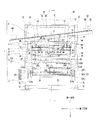
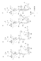
図1は、本発明の一実施形態に係る折割装置の正面図である。FIG. 1 is a front view of a folding device according to an embodiment of the present invention. 図2は、同実施形態に係る折割装置の概略縦断面図であって、図1のI―I断面図である。FIG. 2 is a schematic longitudinal sectional view of the folding device according to the embodiment, which is a sectional view taken along the line II of FIG. 図3は、同実施形態に係る折割装置の概略縦断面図であって、搬送コンベアと並べて設置した状態の概略縦断面図である。FIG. 3 is a schematic vertical cross-sectional view of the folding device according to the embodiment, and is a schematic vertical cross-sectional view of a state where the folding apparatus is installed side by side with the conveyor. 図4は、同実施形態に係る折割装置の動作説明図であって、(A)は、一対の挟持体間に進入したガラスシートを一対の挟持体で挟持した状態であり、(B)は、ガラスシートを挟持した一対の挟持体をガラスシートの進行に合わせて移動させつつ、該一対の挟持体を所定角度回転させた状態であり、(C)は、一方の挟持体を他方の挟持体から離間させつつ一対の挟持体を所定角度回転させた状態であり、(D)は、一方の挟持体を他方の挟持体から離間させている状態である。FIG. 4 is an operation explanatory view of the folding device according to the embodiment, wherein (A) is a state in which a glass sheet that has entered between a pair of sandwiching bodies is sandwiched between a pair of sandwiching bodies, and (B) Is a state in which the pair of sandwiched bodies sandwiched between the glass sheets is moved in accordance with the progress of the glass sheet, and the pair of sandwiched bodies are rotated by a predetermined angle. A state in which the pair of sandwiching bodies is rotated by a predetermined angle while being separated from the sandwiching body, and (D) is a state in which one sandwiching body is separated from the other sandwiching body. 図5は、同実施形態に係る折割装置の動作説明図であって、(A)は、一方の挟持体上のガラス板が搬送コンベアに載置された状態であり、(B)は、搬送コンベアでガラス板が搬送され、一方の挟持体を他方の挟持体に接近させる状態であり、(C)は、一方の挟持体を他方の挟持体に接近させる状態であり、(D)は、ガラスシートを一対の挟持体で挟持した状態である。FIG. 5 is an operation explanatory diagram of the folding device according to the embodiment, in which (A) is a state in which a glass plate on one clamping body is placed on a conveyor, and (B) is A glass plate is conveyed by a conveyor and is in a state in which one sandwiched body is brought closer to the other sandwiched body, (C) is a state in which one sandwiched body is brought closer to the other sandwiched body, and (D) is The glass sheet is sandwiched between a pair of sandwiching bodies.

以下、本発明の一実施形態に係る折割装置について、添付図面を参照しつつ説明する。   Hereinafter, a folding device according to an embodiment of the present invention will be described with reference to the accompanying drawings.

折割装置は、溶融ガラスを長尺なガラスシートに成形する成形装置と並んで配置される。そして、折割装置は、成形装置から連続的に供給されるガラスシートを受け入れ、該ガラスシートを順々に分割して所定サイズのガラス板を作製する。   The folding device is arranged side by side with a molding device that forms molten glass into a long glass sheet. And a folding device receives the glass sheet continuously supplied from a shaping | molding apparatus, divides this glass sheet in order, and produces the glass plate of a predetermined size.

本実施形態に係る折割装置は、上方に配置された成形装置から連続的に供給されるガラスシートを受け入れるべく、成形装置の下方に配置される。すなわち、折割装置は、上下方向で真っ直ぐに延びる進行経路(供給経路)を通って上方から垂下するガラスシートを受け入れ可能に構成される。   The folding device according to the present embodiment is disposed below the molding device so as to receive a glass sheet continuously supplied from the molding device disposed above. In other words, the folding device is configured to receive a glass sheet that hangs down from above through a traveling path (supply path) that extends straight in the vertical direction.

なお、以下の説明において、ガラスシートの進行方向(ガラスシートの通過する進行経路の延びる方向)を「第一方向」といい、第一方向と直交する方向であって、進行経路上にあるガラスシートの広がる方向(幅方向)を「第二方向」といい、第一方向及び第二方向と直交する方向であって、進行経路上にあるガラスシートの厚み方向を「第三方向」ということとする。また、ガラスシートの進行方向(第一方向)において、ガラスシートの進行方向における該ガラスシートの供給側を「上流」又は「上流側」といい、ガラスシートの進行方向における該ガラスシートの先頭側を「下流」又は「下流側」ということとする。   In the following description, the traveling direction of the glass sheet (the direction in which the traveling path through which the glass sheet passes) is referred to as the “first direction”, and is the direction perpendicular to the first direction and on the traveling path. The direction in which the sheet spreads (width direction) is referred to as the “second direction”, the direction perpendicular to the first direction and the second direction, and the thickness direction of the glass sheet on the traveling path is referred to as the “third direction”. And Further, in the glass sheet traveling direction (first direction), the glass sheet supply side in the glass sheet traveling direction is referred to as “upstream” or “upstream side”, and the leading side of the glass sheet in the glass sheet traveling direction. Is referred to as “downstream” or “downstream”.

本実施形態に係る折割装置について具体的に説明すると、折割装置は、図1及び図2に示す如く、第一方向と交差する方向に延び、進行中のガラスシートGsの一方の面S1を支持可能な支持バー2と、支持バー2上を通過したガラスシートGsを挟持可能に構成された挟持装置3と、該挟持装置3がガラスシートGsを挟持し、且つガラスシートGsに予め施された罫書線と支持バー2とが一致した状態で、支持バー2(罫書線)と同方向に延びる軸心回りでガラスシートGsの一方の面側に挟持装置3を回転させる回転用駆動装置4(図2参照)とを備える。   The folding device according to the present embodiment will be described in detail. The folding device extends in a direction intersecting the first direction as shown in FIGS. 1 and 2, and one surface S1 of the ongoing glass sheet Gs. A support bar 2 capable of supporting the glass sheet Gs, a sandwiching device 3 configured to sandwich the glass sheet Gs that has passed over the support bar 2, and the sandwiching device 3 sandwiches the glass sheet Gs and is applied to the glass sheet Gs in advance. Rotation drive device for rotating the clamping device 3 on one surface side of the glass sheet Gs around an axis extending in the same direction as the support bar 2 (ruled line) in a state where the ruled line and the support bar 2 coincide with each other 4 (see FIG. 2).

また、本実施形態において、折割装置1は、支持バー2よりも上流側に配置され、ガラスシートGsの他方の面S2を支持する支持ローラ5,5と、支持バー2及び支持ローラ5,5の上流側に配置され、進行中のガラスシートGsに対して第一方向と交差(直交)する方向に延びる罫書線を施すための罫書線形成装置6とをさらに備える。これに伴い、折割装置1は、支持バー2、挟持装置3、回転用駆動装置4、支持ローラ5,5、及び罫書線形成装置6を支持するフレーム7を備える。   Moreover, in this embodiment, the folding apparatus 1 is arrange | positioned upstream from the support bar 2, the support rollers 5 and 5 which support the other surface S2 of the glass sheet Gs, and the support bar 2 and the support rollers 5, 5 and a ruled line forming device 6 for applying a ruled line extending in a direction intersecting (orthogonal) with the first direction with respect to the ongoing glass sheet Gs. Accordingly, the folding device 1 includes a support bar 2, a clamping device 3, a rotation drive device 4, support rollers 5 and 5, and a frame 7 that supports the ruled line forming device 6.

本実施形態において、支持バー2は、第二方向に延びている。支持バー2は、図2に示す如く、第三方向にガラスシートGsの一方の面S1と対向する第一端部と、その反対側の第二端部とを有する。支持バー2の第一端部は、第二方向におけるガラスシートGsの全域に対向可能になっている。そして、支持バー2の第一端部は、第三方向でガラスシートGsに向けて先細りに形成されている。本実施形態において、支持バー2の第一端部は、第二方向から見て断面半円弧状に形成されており、その外周の一部がガラスシートGsの一方の面S1と線接触するようになっている。   In the present embodiment, the support bar 2 extends in the second direction. As shown in FIG. 2, the support bar 2 has a first end facing the one surface S1 of the glass sheet Gs in the third direction and a second end opposite to the first end. The first end of the support bar 2 can be opposed to the entire area of the glass sheet Gs in the second direction. And the 1st end part of the support bar 2 is tapered toward the glass sheet Gs in the third direction. In the present embodiment, the first end portion of the support bar 2 is formed in a semicircular arc shape when viewed from the second direction, and a part of the outer periphery thereof is in line contact with one surface S1 of the glass sheet Gs. It has become.

支持バー2は、姿勢を保ちつつ第一方向に移動可能に設けられている。より具体的に説明すると、本実施形態に係る折割装置1は、挟持装置3を第一方向に移動させる駆動装置(本実施形態においては、昇降用駆動装置という)8を備えている。   The support bar 2 is provided to be movable in the first direction while maintaining its posture. More specifically, the folding device 1 according to the present embodiment includes a drive device 8 (in this embodiment, referred to as a lift drive device) that moves the clamping device 3 in the first direction.

昇降用駆動装置8は、軸心回りで回転運動する出力軸80を有する電動モータ81と、出力軸80に連結される雄ネジ体82、及び雄ネジ体82に螺合された雌ネジ体83を有する送りネジ機構84とを備えている。   The elevating drive device 8 includes an electric motor 81 having an output shaft 80 that rotates around an axis, a male screw body 82 connected to the output shaft 80, and a female screw body 83 screwed to the male screw body 82. A feed screw mechanism 84 having

昇降用駆動装置8の電動モータ81は、出力軸80を第一方向に配置した状態(ガラスシートGsの進行方向と平行又は略平行にした状態)でフレーム7(後述する第二連結梁部73)に固定されている。送りネジ機構84は、電動モータ81の出力軸80の出力が雄ネジ体82に伝達され、雄ネジ体82が電動モータ81の出力軸80と同心で回転することで、雌ネジ体83を雄ネジ体82の軸心方向に沿って移動させるようになっている。すなわち、送りネジ機構84は、電動モータ81の出力軸80を正逆転させることで、雌ネジ体83を第一方向で往復移動させるようになっている。なお、本実施形態において、送りネジ機構84には、雄ネジ体82と雌ネジ体83とが複数の球体(図示しない)を介して螺合するボールネジが採用されている。   The electric motor 81 of the elevating drive device 8 has the frame 7 (second connecting beam portion 73 to be described later) in a state where the output shaft 80 is disposed in the first direction (a state in which the output shaft 80 is parallel or substantially parallel to the traveling direction of the glass sheet Gs). ). The feed screw mechanism 84 transmits the output of the output shaft 80 of the electric motor 81 to the male screw body 82, and the male screw body 82 rotates concentrically with the output shaft 80 of the electric motor 81. The screw body 82 is moved along the axial direction. That is, the feed screw mechanism 84 reciprocates the female screw body 83 in the first direction by rotating the output shaft 80 of the electric motor 81 forward and backward. In the present embodiment, the feed screw mechanism 84 employs a ball screw in which the male screw body 82 and the female screw body 83 are screwed together via a plurality of spheres (not shown).

これを前提に、本実施形態の折割装置1は、挟持装置3を雄ネジ体82に連結するための支持フレーム9を備えている。また、本実施形態の折割装置1は、支持バー2を支持フレーム9に連結する補助フレーム10を備えている。   Based on this assumption, the folding device 1 of the present embodiment includes a support frame 9 for connecting the clamping device 3 to the male screw body 82. Further, the folding device 1 of this embodiment includes an auxiliary frame 10 that connects the support bar 2 to the support frame 9.

支持フレーム9は、図1及び図2に示す如く、第一方向に間隔をあけて配置された一対の梁部90,90と、一対の梁部90,90同士を連結する連結柱91,…と、回転用駆動装置4の後述する第二モータ(減速機付き電動モータ)40を支持するモータ支持部92と、回転用駆動装置4の後述する第二駆動伝達装置41及び挟持装置3を支持する装置支持部93と、フレーム7(後述する第一脚部70,70)に固定されたレール75,75に沿って移動可能に構成されたスライド体94,…とを備える。   As shown in FIGS. 1 and 2, the support frame 9 includes a pair of beam portions 90 and 90 arranged at intervals in the first direction, and connecting columns 91 that connect the pair of beam portions 90 and 90 to each other. And a motor support portion 92 that supports a second motor (electric motor with a speed reducer) 40, which will be described later, of the rotation drive device 4, and a second drive transmission device 41 and a clamping device 3, which will be described later, of the rotation drive device 4. And a slide body 94 configured to be movable along rails 75 fixed to the frame 7 (first leg portions 70 and 70 described later).

一対の梁部90,90及び連結柱91,…は、角形鋼管で構成されている。そして、本実施形態において、連結柱91,…は、第二方向に間隔をあけて複数(本実施形態においては四つ)設けられている。   The pair of beam portions 90, 90 and the connecting pillars 91, ... are formed of a square steel pipe. In this embodiment, a plurality (four in this embodiment) of connecting pillars 91,... Are provided at intervals in the second direction.

本実施形態において、モータ支持部92は、四つの連結柱91,…のうちの中央側にある連結柱91に固定されている(図1参照)。これに対し、装置支持部93は、四つの連結柱91,…のうちの両端にある二つの連結柱91,…のそれぞれに固定されている(図1参照)。装置支持部93のそれぞれは、第三方向に長手をなし、第三方向に第一端部及び第二端部を有する。装置支持部93は、連結柱91,…と交差する態様をなしており、第一端部を挟持装置3側に向けている(図2参照)。そして、装置支持部93の第一端部及び第二端部には、軸受(採番しない)が取り付けられている。   In the present embodiment, the motor support portion 92 is fixed to the connecting column 91 on the center side of the four connecting columns 91,... (See FIG. 1). On the other hand, the apparatus support part 93 is being fixed to each of the two connection pillars 91 and ... in the both ends of the four connection pillars 91 and ... (refer FIG. 1). Each of the device support portions 93 has a length in the third direction and has a first end portion and a second end portion in the third direction. The apparatus support part 93 has made the aspect which cross | intersects the connection pillar 91, ..., and has turned the 1st end part to the clamping apparatus 3 side (refer FIG. 2). And the bearing (not numbered) is attached to the 1st end part and 2nd end part of the apparatus support part 93. FIG.

本実施形態において、スライド体94,…は、一対の梁部90,90のそれぞれの両端(四箇所)に対応して設けられている。本実施形態において、レール75,75は、第二方向に間隔をあけて二本設けられており、一対の梁部90,90のそれぞれの一端側に設けられたスライド体94,…が一方のレール75に案内され、一対の梁部90,90のそれぞれの他端側に設けられたスライド体94,…が他方のレール75に案内されるようになっている。これにより、スライド体94,…のそれぞれがレール75,75に案内されることで、支持フレーム9全体が第一方向に移動するようになっている。   In the present embodiment, the slide bodies 94,... Are provided corresponding to both ends (four locations) of the pair of beam portions 90, 90, respectively. In this embodiment, two rails 75, 75 are provided at intervals in the second direction, and one slide body 94,... Provided on one end side of each of the pair of beam portions 90, 90 is one. Guided by the rail 75, the slide bodies 94 provided on the other end sides of the pair of beam portions 90, 90 are guided by the other rail 75. As a result, each of the slide bodies 94,... Is guided by the rails 75, 75, so that the entire support frame 9 moves in the first direction.

そして、図2に示す如く、昇降用駆動装置8の雌ネジ体83は、一対の梁部90のうちの第一方向の上流側にある一方の梁部90に連結されている。これにより、支持フレーム9は、昇降用駆動装置8の駆動で第一方向に移動するようになっている。   As shown in FIG. 2, the female screw body 83 of the elevating drive device 8 is connected to one beam portion 90 on the upstream side in the first direction of the pair of beam portions 90. As a result, the support frame 9 is moved in the first direction by the drive of the elevating drive device 8.

補助フレーム10は、支持フレーム9(本実施形態においては一対の梁部90,90のうち、第一方向の上流側にある一方の梁部90)に連結され、支持バー2が第二方向に延びた姿勢となるように、支持バー2の基端部が連結されている。これにより、支持バー2が昇降用駆動装置8の駆動で第一方向に移動するようになっている。すなわち、支持バー2は、昇降用駆動装置8の送りネジ機構84(雌ネジ体83)に間接的に連結されることで、挟持装置3と一緒に第一方向に移動するようになっている。   The auxiliary frame 10 is connected to the support frame 9 (in this embodiment, one of the pair of beam portions 90, 90 on the upstream side in the first direction), and the support bar 2 extends in the second direction. The base end part of the support bar 2 is connected so that it may become the extended attitude | position. As a result, the support bar 2 is moved in the first direction by the drive of the elevating drive device 8. In other words, the support bar 2 moves indirectly in the first direction together with the clamping device 3 by being indirectly connected to the feed screw mechanism 84 (female screw body 83) of the elevating drive device 8. .

挟持装置3は、上述の如く、支持バー2と同方向に延びる軸心回りで回転可能に設けられる。本実施形態において、挟持装置3の回転中心(回転中心となる軸心)は、ガラスシートGsの進行経路Rから離れた位置に設定されている。   As described above, the clamping device 3 is provided so as to be rotatable around an axis extending in the same direction as the support bar 2. In the present embodiment, the center of rotation of the clamping device 3 (the axis that is the center of rotation) is set at a position away from the traveling path R of the glass sheet Gs.

ここで挟持装置3について具体的に説明すると、挟持装置3は、第一端部と該第一端部の反対側の第二端部とを有し、互いの第一端部同士が支持バー2と同方向に延びる軸心回りで相対回転可能に連結された一対の挟持体30,31であって、進行中のガラスシートGsが第二端部側から第一端部に向けて互いの間に進入可能に配置された一対の挟持体30,31と、一対の挟持体30,31の第二端部同士を接離させるべく、一対の挟持体30,31を相対回転させる挟持用駆動装置32とを備える。また、本実施形態に係る挟持装置3は、分割されたガラスシート(ガラス板)が第一挟持体30と第二挟持体31との間から脱落するのを防止するガラス受体33を備えている。   Here, the clamping device 3 will be described in detail. The clamping device 3 has a first end portion and a second end portion on the opposite side of the first end portion. 2, a pair of sandwiching bodies 30, 31 connected so as to be relatively rotatable around an axis extending in the same direction as 2, and the glass sheet Gs in progress is mutually connected from the second end side toward the first end part. A pair of sandwiching bodies 30, 31 arranged so as to be able to enter between them, and a pair of sandwiching bodies 30, 31 for rotating the pair of sandwiching bodies 30, 31 to rotate relative to each other in order to bring the second ends into contact with or away from each other Device 32. Moreover, the clamping device 3 according to the present embodiment includes a glass receiver 33 that prevents the divided glass sheet (glass plate) from falling off between the first clamping body 30 and the second clamping body 31. Yes.

一対の挟持体30,31のそれぞれは、それぞれが第二方向に延びる軸心を有し、該軸心回りで回転自在に構成された複数のローラ体300,…,310,…を備えている。   Each of the pair of sandwiching bodies 30 and 31 includes a plurality of roller bodies 300,..., 310,... Each having an axis extending in the second direction and configured to be rotatable around the axis. .

より具体的には、一対の挟持体30,31のうちの一方の挟持体(以下、第一挟持体という)30は、図1及び図2に示す如く、第二方向に間隔をあけて配置された一対のフレームプレート301,301と、それぞれの軸心同士が平行になるように第一方向に間隔をあけて配置され、それぞれの両端部が一対のフレームプレート301,301に回転自在に軸支された複数のローラ体300,…とを備えている。   More specifically, one of the pair of sandwiching bodies 30 and 31 (hereinafter referred to as the first sandwiching body) 30 is arranged with a gap in the second direction as shown in FIGS. The pair of frame plates 301 and 301 are arranged with a space in the first direction so that the respective axes are parallel to each other, and both end portions of the pair of frame plates 301 and 301 are pivoted to the pair of frame plates 301 and 301, respectively. A plurality of supported roller bodies 300 are provided.

第一挟持体30における一対のフレームプレート301,301のそれぞれは、一方向に長手をなし、長手方向に第一端部と第二端部とを有する。第一挟持体30における一対のフレームプレート301,301のそれぞれの第一端部には、第二方向に延びる第一回転軸302が挿通された状態で固定されている。   Each of the pair of frame plates 301, 301 in the first clamping body 30 has a longitudinal direction in one direction, and has a first end portion and a second end portion in the longitudinal direction. A first rotating shaft 302 extending in the second direction is fixed to a first end of each of the pair of frame plates 301 and 301 in the first sandwiching body 30 in a state where the first rotating shaft 302 is inserted.

第一挟持体30のフレームプレート301,301には、長手方向に間隔をあけて複数の軸受(図示しない)が取り付けられている。   A plurality of bearings (not shown) are attached to the frame plates 301 and 301 of the first sandwiching body 30 at intervals in the longitudinal direction.

第一挟持体30の複数のローラ体300,…のそれぞれは、第二方向に延びる軸体303と、該軸体303に外嵌された複数のローラ部304,…(図1参照)とを有する。複数のローラ部304,…のそれぞれは、弾性を有する樹脂或いはゴムで成形されたもので、軸体303よりも大径の円柱状に形成されている。第一挟持体30において、複数のローラ体300,…のそれぞれの軸体303の両端部は、第一挟持体30の一対のフレームプレート301,301に設けられた複数の軸受のそれぞれに回転自在に軸支されている。   Each of the plurality of roller bodies 300,... Of the first clamping body 30 includes a shaft body 303 extending in the second direction, and a plurality of roller portions 304, ... (see FIG. 1) externally fitted to the shaft body 303. Have. Each of the plurality of roller portions 304,... Is formed of elastic resin or rubber, and is formed in a columnar shape having a larger diameter than the shaft body 303. In the first clamping body 30, both end portions of the shaft bodies 303 of the plurality of roller bodies 300,... Are freely rotatable with respect to the plurality of bearings provided on the pair of frame plates 301, 301 of the first clamping body 30. Is pivotally supported.

一対の挟持体30,31のうちの他方の挟持体31(以下、第二挟持体という)は、図2に示す如く、第二方向に間隔をあけて配置された一対のフレームプレート311,311と、それぞれの軸心同士が平行となるように第一方向に間隔をあけて配置され、それぞれの両端部が一対のフレームプレート311,311に回転自在に軸支された複数のローラ体310,…とを備えている。   The other holding body 31 (hereinafter referred to as a second holding body) of the pair of holding bodies 30 and 31 is a pair of frame plates 311 and 311 arranged at intervals in the second direction, as shown in FIG. A plurality of roller bodies 310 that are arranged at intervals in the first direction so that the respective axes are parallel to each other, and whose both end portions are rotatably supported by a pair of frame plates 311, 311, … And.

第二挟持体31における一対のフレームプレート311,311のそれぞれは、一方向に長手をなし、長手方向に第一端部と第二端部とを有する。   Each of the pair of frame plates 311 and 311 in the second clamping body 31 has a length in one direction, and has a first end and a second end in the length direction.

第二挟持体31における一対のフレームプレート311,311のそれぞれの第一端部には、第三方向の一方側に延出した第一支軸部314aが設けられるとともに、第一支軸部314aとは反対側に延出した第二支軸部314bが設けられている。第一支軸部314a及び第二支軸部314bのそれぞれには、軸受(採番しない)が取り付けられている。そして、一対のフレームプレート311,311の第一支軸部314a(軸受)は、第一挟持体30の第一回転軸302を回転自在に軸支している。これにより、第一挟持体30及び第二挟持体31は、支持バー2と同方向に延びる軸心(第二方向に延びる第一回転軸302)回りで相対回転可能に設けられている。   A first support shaft portion 314a extending to one side in the third direction is provided at each first end portion of the pair of frame plates 311 and 311 in the second sandwiching body 31, and the first support shaft portion 314a. The 2nd spindle part 314b extended to the opposite side is provided. A bearing (not numbered) is attached to each of the first support shaft portion 314a and the second support shaft portion 314b. The first support shaft portions 314a (bearings) of the pair of frame plates 311 and 311 rotatably support the first rotation shaft 302 of the first sandwiching body 30. Thereby, the 1st clamping body 30 and the 2nd clamping body 31 are provided so that relative rotation is possible around the axial center (1st rotating shaft 302 extended in a 2nd direction) extended in the same direction as the support bar 2. As shown in FIG.

また、第二挟持体31の第一端部側には挟持用駆動装置32の後述する第一モータ(減速機付き電動モータ)320が取り付けられるモータベース(採番しない)が設けられている。第二挟持体31のフレームプレート311,311の第二端部は、第三方向であって、第一支軸部314aとは反対側に向けて屈曲している。そして、第二挟持体31のフレームプレート311,311の第二端部には、第二方向に延びる第二回転軸315が挿通された状態で固定されている。そして、第二回転軸315は、支持フレーム9における一対の装置支持部93,93のそれぞれの第一端部に設けられた軸受(図示しない)によって回転自在に軸支されている。これにより、本実施形態に係る挟持装置3は、ガラスシートGsの進行経路Rから離れた位置にある軸心(第二回転軸315)回りで回転可能になっている。具体的には、本実施形態に係る挟持装置3は、進行経路R上を通過するガラスシートGsの一方の面側S1であって、進行経路Rから第三方向で所定距離離れ、且つ支持バー2よりも上流側であって、支持バー2よりも第一方向で所定距離離れた位置を回転中心にして回転するようになっている。   A motor base (not numbered) to which a later-described first motor (electric motor with a speed reducer) 320 of the clamping drive device 32 is attached is provided on the first end portion side of the second clamping body 31. The second end portions of the frame plates 311 and 311 of the second sandwiching body 31 are bent in the third direction toward the side opposite to the first support shaft portion 314a. And the 2nd rotating shaft 315 extended in a 2nd direction is being fixed to the 2nd end part of the frame plates 311 and 311 of the 2nd clamping body 31 in the state penetrated. The second rotary shaft 315 is rotatably supported by bearings (not shown) provided at the first end portions of the pair of device support portions 93 and 93 in the support frame 9. Thereby, the clamping apparatus 3 which concerns on this embodiment can be rotated around the shaft center (2nd rotating shaft 315) in the position away from the advancing path | route R of the glass sheet Gs. Specifically, the clamping device 3 according to the present embodiment is one surface side S1 of the glass sheet Gs that passes on the traveling path R, is separated from the traveling path R by a predetermined distance in the third direction, and is a support bar. It is upstream of 2 and rotates around a position that is a predetermined distance away from the support bar 2 in the first direction.

第二挟持体31のフレームプレート311,311には、長手方向に間隔をあけて複数の軸受(図示しない)が取り付けられている。   A plurality of bearings (not shown) are attached to the frame plates 311 and 311 of the second clamping body 31 at intervals in the longitudinal direction.

第二挟持体31の複数のローラ体310,…のそれぞれは、第二方向に延びる軸体312と、該軸体312に同心で外嵌された複数のローラ部313,…とを有する。複数のローラ部313,…のそれぞれは、弾性を有する樹脂或いはゴムで成形されたもので、軸体312よりも大径の円柱状に形成されている。第二挟持体31において、複数のローラ体310,…のそれぞれの軸体312の両端部は、第二挟持体31の一対のフレームプレート311,311に設けられた複数の軸受のそれぞれに回転自在に軸支されている。   Each of the plurality of roller bodies 310 of the second clamping body 31 includes a shaft body 312 extending in the second direction, and a plurality of roller portions 313,. Each of the plurality of roller portions 313,... Is formed of an elastic resin or rubber, and is formed in a columnar shape having a larger diameter than the shaft body 312. In the second clamping body 31, both end portions of the shaft bodies 312 of the plurality of roller bodies 310,... Are freely rotatable with respect to the plurality of bearings provided on the pair of frame plates 311, 311 of the second clamping body 31. Is pivotally supported.

第一挟持体30及び第二挟持体31のそれぞれのローラ体300,…,310,…の配置は、互いに対応している。すなわち、第一回転軸302を中心にして第一挟持体30及び第二挟持体31を相対的に回転させ、該第一挟持体30と第二挟持体31とを接近させた状態で、互いのローラ体300,310(ローラ部304,313)同士が対向し、第一挟持体30と第二挟持体31との間に進入したガラスシートGsを対向するローラ体300,310で挟持できるようになっている。なお、第一挟持体30及び第二挟持体31は、互いのローラ体300,310同士が対向した状態で、ローラ体300,310間がガラスシートGsの進行経路Rと一致するように配置される。   The arrangement of the roller bodies 300,..., 310,... Of the first clamping body 30 and the second clamping body 31 correspond to each other. That is, the first sandwiching body 30 and the second sandwiching body 31 are relatively rotated around the first rotation shaft 302 so that the first sandwiching body 30 and the second sandwiching body 31 are brought close to each other. Roller bodies 300 and 310 (roller portions 304 and 313) face each other so that the glass sheet Gs that has entered between the first sandwiching body 30 and the second sandwiching body 31 can be sandwiched by the facing roller bodies 300 and 310. It has become. In addition, the 1st clamping body 30 and the 2nd clamping body 31 are arrange | positioned so that the roller bodies 300 and 310 may correspond with the advancing path | route R of the glass sheet Gs in the state which mutually opposed roller bodies 300 and 310 faced each other. The

挟持用駆動装置32は、減速機付き電動モータ(以下、第一モータという)320と、第一モータ320の駆動を第一挟持体30の第一回転軸302に伝達する駆動伝達装置(以下、第一駆動伝達装置という)321とを備えている。第一駆動伝達装置321は、第一モータ320の出力を受ける駆動軸(以下、第一駆動軸という)322と、第一駆動軸322に取り付けられた回転体(以下、第一回転体という)323と、第一挟持体30に固定された第一回転軸302に取り付けられた回転体(以下、第二回転体という)324と、第一回転体323と第二回転体324とのトルク伝達可能に架け渡された無端環状体(以下、第一無端環状体という)325とを備える。   The clamping drive device 32 includes an electric motor with a speed reducer (hereinafter referred to as a first motor) 320 and a drive transmission device (hereinafter referred to as a first rotation shaft 302) of the first clamping body 30. 321) (referred to as a first drive transmission device). The first drive transmission device 321 includes a drive shaft (hereinafter referred to as a first drive shaft) 322 that receives the output of the first motor 320, and a rotating body (hereinafter referred to as a first rotating body) attached to the first drive shaft 322. 323, a rotating body (hereinafter referred to as a second rotating body) 324 attached to a first rotating shaft 302 fixed to the first clamping body 30, and torque transmission between the first rotating body 323 and the second rotating body 324. And an endless annular body (hereinafter referred to as a first endless annular body) 325 that is bridged over.

本実施形態に係る第一モータ320は、減速機に第一駆動軸322を挿通可能なタイプのものが採用されている。これに伴い、第一駆動軸322は、第一モータ320の両側から延出し、第二方向の両側が第二挟持体31のフレームプレート311,311の第二支軸部314bに取り付けられた軸受によって回転自在に軸支されている。第一回転体323は、第一駆動軸322の両端部のそれぞれに取り付けられている。これに対し、第二回転体324は、第一挟持体30の第一回転軸302の両端部のそれぞれに取り付けられている。本実施形態において、第一無端環状体325には歯付きベルトが採用されている。これに伴い、第一回転体323及び第二回転体324のそれぞれには歯付き車が採用されている。これにより、第一モータ320の出力を受けて第一駆動軸322が回転すると第一回転体323が回転し、第一無端環状体325に回転が伝達される。これにより、第二回転体324が回転し、第二回転体324が取り付けられた第一回転軸302とともに第一挟持体30が同心で回転するようになっている。   The first motor 320 according to the present embodiment is of a type that allows the first drive shaft 322 to be inserted into the speed reducer. Accordingly, the first drive shaft 322 extends from both sides of the first motor 320, and both sides in the second direction are bearings attached to the second support shaft portions 314b of the frame plates 311 and 311 of the second sandwiching body 31. Is rotatably supported by the shaft. The first rotating body 323 is attached to each of both end portions of the first drive shaft 322. On the other hand, the second rotating body 324 is attached to each of both end portions of the first rotating shaft 302 of the first sandwiching body 30. In the present embodiment, a toothed belt is employed for the first endless annular body 325. Accordingly, a toothed wheel is adopted for each of the first rotating body 323 and the second rotating body 324. Accordingly, when the first drive shaft 322 rotates in response to the output of the first motor 320, the first rotating body 323 rotates and the rotation is transmitted to the first endless annular body 325. Thereby, the 2nd rotary body 324 rotates and the 1st clamping body 30 rotates concentrically with the 1st rotating shaft 302 to which the 2nd rotary body 324 was attached.

ガラス受体33は、第一挟持体30から第二挟持体31に向けて延出している。具体的には、ガラス受体33は、第二方向に延びるように形成されている。そして、ガラス受体33は、第一挟持体30の一対のフレームプレート301,301に跨るように該フレームプレート301の第一端部に接続されている。これにより、ガラス受体33は、分割されたガラスシート(ガラス板)の先端(進行中に先頭になる端)を支持可能に構成されている。   The glass receiver 33 extends from the first sandwiching body 30 toward the second sandwiching body 31. Specifically, the glass receiver 33 is formed to extend in the second direction. The glass receiver 33 is connected to the first end of the frame plate 301 so as to straddle the pair of frame plates 301, 301 of the first sandwiching body 30. Thereby, the glass receiver 33 is comprised so that support of the front-end | tip (end which becomes a head in progress) of the divided | segmented glass sheet (glass plate) is possible.

回転用駆動装置4は、減速機付き電動モータ(以下、第二モータという)40と、第二モータ40の駆動を第二挟持体31の第二回転軸315に伝達する駆動伝達装置(以下、第二駆動伝達装置という)41とを備えている。本実施形態に係る第二駆動伝達装置41は、第二モータ40の出力を受ける駆動軸(以下、第二駆動軸という)42と、第二駆動軸42に取り付けられた回転体(以下、第三回転体という)43と、第二挟持体31に固定された第二回転軸315に取り付けられた回転体(以下、第四回転体という)44と、第三回転体43と第四回転体44とのトルク伝達可能に架け渡された無端環状体(以下、第二無端環状体という)45とを備える。   The rotation drive device 4 includes an electric motor with a speed reducer (hereinafter referred to as a second motor) 40 and a drive transmission device (hereinafter referred to as a second rotation shaft 315) that transmits the drive of the second motor 40 to the second rotating shaft 315 of the second clamping body 31. 41) (referred to as a second drive transmission device). The second drive transmission device 41 according to this embodiment includes a drive shaft (hereinafter referred to as a second drive shaft) 42 that receives the output of the second motor 40, and a rotating body (hereinafter referred to as a first drive shaft 42) attached to the second drive shaft 42. A third rotating body 43, a rotating body (hereinafter referred to as a fourth rotating body) 44 attached to a second rotating shaft 315 fixed to the second clamping body 31, a third rotating body 43, and a fourth rotating body. And an endless annular body (hereinafter referred to as a second endless annular body) 45 that is bridged so as to be able to transmit torque with the shaft 44.

本実施形態に係る第二モータ40は、減速機に第二駆動軸42を挿通可能なタイプのものが採用されている。これに伴い、第二駆動軸42は、第二モータ40の両側から延出し、第二方向における両側が一対の装置支持部93の第二端部に設けられた軸受によって回転自在に軸支されている。そして、第三回転体43は、第二駆動軸42に取り付けられている。これに対し、第四回転体44は、第二挟持体31の第二回転軸315に取り付けられている。本実施形態において、第三回転体43は、第二駆動軸42における第二方向に間隔をあけた二箇所に取り付けられ、第四回転体44は、第三回転体43の配置に対応するように、第二回転軸315における第二方向に間隔をあけた二箇所に取り付けられている。本実施形態において、第二無端環状体45には歯付きベルトが採用されている。これに伴い、第三回転体43及び第四回転体44のそれぞれには歯付き車が採用されている。これにより、第二モータ40の出力を受けて第二駆動軸42が回転すると第三回転体43が回転し、第二無端環状体45に回転力が伝達される。これにより、第四回転体44が回転し、第四回転体44が取り付けられた第二回転軸315とともに第二挟持体31が同心で回転する。そして、第二挟持体31には第一回転軸302を介して第一挟持体30が連結されているため、第二挟持体31とともに第一挟持体30も同心で回転するようになっている。   As the second motor 40 according to the present embodiment, a type in which the second drive shaft 42 can be inserted into the speed reducer is employed. Accordingly, the second drive shaft 42 extends from both sides of the second motor 40, and both sides in the second direction are rotatably supported by bearings provided at the second ends of the pair of device support portions 93. ing. The third rotating body 43 is attached to the second drive shaft 42. On the other hand, the fourth rotating body 44 is attached to the second rotating shaft 315 of the second clamping body 31. In the present embodiment, the third rotator 43 is attached to two locations spaced in the second direction on the second drive shaft 42, and the fourth rotator 44 corresponds to the arrangement of the third rotator 43. In addition, the second rotary shaft 315 is attached at two locations spaced in the second direction. In the present embodiment, a toothed belt is employed for the second endless annular body 45. Accordingly, a toothed wheel is adopted for each of the third rotating body 43 and the fourth rotating body 44. As a result, when the second drive shaft 42 rotates in response to the output of the second motor 40, the third rotating body 43 rotates and the rotational force is transmitted to the second endless annular body 45. Thereby, the 4th rotary body 44 rotates and the 2nd clamping body 31 rotates concentrically with the 2nd rotating shaft 315 to which the 4th rotary body 44 was attached. And since the 1st clamping body 30 is connected with the 2nd clamping body 31 via the 1st rotating shaft 302, the 1st clamping body 30 also rotates concentrically with the 2nd clamping body 31. FIG. .

支持ローラ5,5は、ガラスシートGsの進行経路Rを境にした領域のうち、支持バー2の存在する領域の反対側の領域に配置されている。本実施形態において、支持ローラ5,5は、第一方向に間隔をあけて二つ設けられている。支持ローラ5,5は、第二方向に延びる軸体50と、該軸体50に外嵌された複数のローラ部51,…とを有する。複数のローラ部51,…は、当該支持ローラ5,5の回転中心の延びる方向(第二方向)に間隔をあけて配置されている(図1参照)。そして、支持ローラ5,5は、支持バー2とは異なり、フレーム7に固定され、一定の位置で回転自在に設けられている。なお、上述の如く、支持バー2は、第一方向で移動可能に設けられるが、支持ローラ5,5は、支持バー2が第一方向の上流側の移動限界位置に位置しても、支持バー2よりも上流側に位置するように配置されている。   The support rollers 5 and 5 are disposed in a region on the opposite side of the region where the support bar 2 is present in the region having the travel path R of the glass sheet Gs as a boundary. In the present embodiment, two support rollers 5 and 5 are provided at intervals in the first direction. The support rollers 5 and 5 include a shaft body 50 extending in the second direction, and a plurality of roller portions 51,. The plurality of roller portions 51 are arranged at intervals in a direction (second direction) in which the rotation center of the support rollers 5 and 5 extends (see FIG. 1). Unlike the support bar 2, the support rollers 5 and 5 are fixed to the frame 7 and are rotatably provided at fixed positions. As described above, the support bar 2 is provided so as to be movable in the first direction. However, the support rollers 5 and 5 are supported even when the support bar 2 is located at the movement limit position on the upstream side in the first direction. It arrange | positions so that it may be located upstream from the bar 2. FIG.

罫書線形成装置6は、図1及び図2に示す如く、第一方向の上流側の定位置に配置されている。そして、罫書線形成装置6は、進行中のガラスシートGsの一方の面S1を支持するガラス支持装置60と、進行中のガラスシートGsの他方の面S2を規制する規制ローラ61と、ガラス支持装置60に支持されたガラスシートGsの他方の面S2上に罫書線を付加する罫書線付加装置62とを備える。   As shown in FIGS. 1 and 2, the ruled line forming device 6 is disposed at a fixed position on the upstream side in the first direction. The ruled line forming device 6 includes a glass support device 60 that supports one surface S1 of the ongoing glass sheet Gs, a regulation roller 61 that regulates the other surface S2 of the ongoing glass sheet Gs, and a glass support. A ruled line adding device 62 for adding a ruled line on the other surface S2 of the glass sheet Gs supported by the device 60 is provided.

ガラス支持装置60は、支持バー2と同じく、ガラスシートGsの一方の面S1を支持する。本実施形態に係るガラス支持装置60は、フレーム7に支持され、ガラスシートGsの一方の面S1の全幅(第二方向の全長)に亘って対向する。より具体的には、ガラス支持装置60は、第一方向に間隔をあけて配置された一対のプーリー63,63と、一対のプーリー63,63に架け渡された平ベルト64とを備える。本実施形態において、フレーム7の後述する一対の第一脚部70のそれぞれに一対の支持プレート(採番しない)が連結されている。一対の支持プレートは、フレーム7(第一脚部70)からガラスシートGsの進行経路R側に延出し、一対のプーリー63,63の両端を軸支している。これにより、ガラス支持装置60(プーリー63,平ベルト64)は、ガラスシートGsの進行経路Rに対する相対位置が一定又は略一定な状態で維持する。すなわち、本実施形態に係るガラス支持装置60は、一定の配置で維持し、一対のプーリー63,63間にある平ベルト64が進行経路R上で進行するガラスシートGsの一方の面S1の全幅を支持するように構成されている。   Similar to the support bar 2, the glass support device 60 supports one surface S <b> 1 of the glass sheet Gs. The glass support device 60 according to the present embodiment is supported by the frame 7 and faces the entire width (the total length in the second direction) of one surface S1 of the glass sheet Gs. More specifically, the glass support device 60 includes a pair of pulleys 63 and 63 that are spaced apart from each other in the first direction, and a flat belt 64 that spans the pair of pulleys 63 and 63. In the present embodiment, a pair of support plates (not numbered) are connected to each of a pair of first leg portions 70 described later of the frame 7. The pair of support plates extend from the frame 7 (first leg portion 70) to the traveling path R side of the glass sheet Gs, and pivotally support both ends of the pair of pulleys 63 and 63. Thereby, the glass support device 60 (the pulley 63, the flat belt 64) maintains the relative position of the glass sheet Gs with respect to the traveling path R in a constant or substantially constant state. That is, the glass support device 60 according to the present embodiment is maintained in a fixed arrangement, and the full width of one surface S1 of the glass sheet Gs in which the flat belt 64 between the pair of pulleys 63 and 63 travels on the travel path R. It is comprised so that it may support.

規制ローラ61は、ガラスシートGsの他方の面S2の全幅(第二方向の全長)に亘って対向する。該規制ローラ61は、第二方向に延びる軸心を有し、該軸心回りで回転自在に構成される。規制ローラ61は、ガラス支持装置60における一対のプーリー63,63のうち、第一方向の上流側にある一方のプーリー63と対向するように配置されている。   The regulating roller 61 is opposed across the entire width (the entire length in the second direction) of the other surface S2 of the glass sheet Gs. The restriction roller 61 has an axis extending in the second direction, and is configured to be rotatable around the axis. The regulation roller 61 is disposed so as to face one pulley 63 on the upstream side in the first direction among the pair of pulleys 63 and 63 in the glass support device 60.

罫書線付加装置62は、第一方向及び第二方向に対して傾斜する傾斜レール65と、傾斜レール65上を移動する罫書装置66とを備える。罫書装置66は、ガラスシートGsの他方の面S2と対向する部位に、該ガラスシートGsの他方の面S2に接触する罫書チップCを備える(図2参照)。また、罫書装置66は、図示しない走行機構を有する。走行機構は、罫書装置66を進行中のガラスシートGsの進行速度に対応させて傾斜レール65上で走行させる。これにより、罫書装置66は、ガラスシートGsに対して第二方向に真っ直ぐ延びる罫書線を形成する。   The ruled line adding device 62 includes an inclined rail 65 that is inclined with respect to the first direction and the second direction, and a ruler device 66 that moves on the inclined rail 65. The scribing device 66 includes a scribing chip C in contact with the other surface S2 of the glass sheet Gs at a portion facing the other surface S2 of the glass sheet Gs (see FIG. 2). Further, the ruler device 66 has a travel mechanism (not shown). The traveling mechanism causes the scoring device 66 to travel on the inclined rail 65 in accordance with the traveling speed of the ongoing glass sheet Gs. As a result, the ruler 66 forms a ruled line that extends straight in the second direction with respect to the glass sheet Gs.

フレーム7は、第二方向に間隔をあけて配置された一対の第一脚部70,70と、第二方向に間隔をあけて配置され、一対の第一脚部70,70に対して第三方向に間隔をあけて配置された一対の第二脚部71,71と、第一脚部70,70と第二脚部71,71とを連結する第一連結梁部72,72と、一対の第一脚部70,70同士を連結する第二連結梁部73,73と、一対の第二脚部71,71同士を連結する第三連結梁部74,74とを備える。   The frame 7 is arranged with a pair of first leg portions 70, 70 spaced apart in the second direction and spaced apart in the second direction, and is first with respect to the pair of first leg portions 70, 70. A pair of second leg portions 71, 71 arranged at intervals in three directions; first connecting beam portions 72, 72 connecting the first leg portions 70, 70 and the second leg portions 71, 71; The second connecting beam portions 73 and 73 that connect the pair of first leg portions 70 and 70 and the third connecting beam portions 74 and 74 that connect the pair of second leg portions 71 and 71 to each other are provided.

前記昇降用駆動装置8及び支持フレーム9は、第一脚部70,70と第二脚部71,71との間に配置されている。そして、第一脚部70,70の第二脚部71,71と対向する面(以下、この面の内面といい、反対側の面を外面という)には、支持フレーム9を案内するレール75,75が取り付けられ、外面よりも外方に、一対の挟持体30,31(第一挟持体30、及び第二挟持体31)、支持バー2、支持ローラ5,5、罫書線形成装置6が配置されている。なお、支持ローラ5,5及び罫書線形成装置6のガラス支持装置60は、フレーム7における第一脚部70,70の外面に固定されている。   The elevating drive device 8 and the support frame 9 are disposed between the first leg portions 70 and 70 and the second leg portions 71 and 71. A rail 75 for guiding the support frame 9 is provided on a surface of the first leg portions 70, 70 facing the second leg portions 71, 71 (hereinafter referred to as an inner surface of this surface, and an opposite surface is referred to as an outer surface). 75, and a pair of sandwiching bodies 30 and 31 (the first sandwiching body 30 and the second sandwiching body 31), the support bar 2, the support rollers 5 and 5, and the ruled line forming device 6 outward from the outer surface. Is arranged. The supporting rollers 5 and 5 and the glass supporting device 60 of the ruled line forming device 6 are fixed to the outer surfaces of the first leg portions 70 and 70 in the frame 7.

本実施形態に係る折割装置1は、以上の通りであり、図3に示す如く、搬送コンベアCnと並列に配置がされる。なお、本実施形態において、搬送コンベアCnは、複数のローラCr,…が横並びに配置されるローラコンベアが採用され、分割されたガラスシート(ガラス板)の挟持を解除した状態(第一挟持体30が傾倒した状態)で、第一挟持体30のローラ体300,…間に該搬送コンベアCnのローラCr,…が介在するように配置される。   The folding device 1 according to the present embodiment is as described above, and is arranged in parallel with the transport conveyor Cn as shown in FIG. In this embodiment, the conveyer Cn employs a roller conveyer in which a plurality of rollers Cr,... Are arranged side by side, and the nipping of the divided glass sheet (glass plate) is released (first nipping body) 30 in a tilted state), the rollers Cr,... Of the conveyor Cn are disposed between the roller bodies 300,.

ここで本実施形態に係る折割装置1の作動について、具体的に説明する。成型装置でシート状に成型されたガラスシートGsは、上方から連続的に下降(進行)する。これに伴い、ガラスシートGsは、まず、ガラス支持装置60と規制ローラ61との間に進入する。そして、ガラスシートGsが所定量進行し、ガラスシートGsの先頭から罫書線形成装置6の罫書チップCまでの距離が所定サイズに対応した距離になると、罫書装置66がガラスシートGsの進行速度に対応する速度で傾斜レール65に沿って移動する。すなわち、ガラスシートGsは、連続的に進行するため、罫書装置66が第一方向及び第二方向に対して傾斜する軌道を辿り、また、罫書装置66の移動速度をガラスシートGsの進行速度に対応させると、罫書装置66(罫書チップC)がガラスシートGsを追いかけながら第一方向及び第二方向と交差する方向に移動する。   Here, the operation of the folding device 1 according to the present embodiment will be specifically described. The glass sheet Gs formed into a sheet shape by the forming apparatus is continuously lowered (advanced) from above. Along with this, the glass sheet Gs first enters between the glass support device 60 and the regulating roller 61. When the glass sheet Gs advances by a predetermined amount, and the distance from the top of the glass sheet Gs to the crease chip C of the crease line forming device 6 becomes a distance corresponding to a predetermined size, the crease device 66 reaches the progress speed of the glass sheet Gs. It moves along the inclined rail 65 at a corresponding speed. That is, since the glass sheet Gs advances continuously, the scoring device 66 follows a trajectory inclined with respect to the first direction and the second direction, and the moving speed of the scribing device 66 is set to the traveling speed of the glass sheet Gs. If it respond | corresponds, the crease apparatus 66 (crease chip | tip C) will move to the direction which cross | intersects a 1st direction and a 2nd direction, chasing the glass sheet Gs.

このとき、ガラス支持装置60の平ベルト64は、ガラスシートGsに追従して回転しつつ、ガラスシートGsの一方の面を支持する。従って、ガラスシートGsの他方の面に罫書チップCが接触しても(押し当てられても)ガラスシートGsが撓むことがなく、ガラスシートGsに対して第二方向に真っ直ぐに延びる罫書線が形成される。そして、罫書装置66は、元の位置に戻り、ガラスシートGsが所定サイズに対応した距離だけ移動する(罫書チップCの位置が先に形成された罫書線から所定距離離れた位置になる)と、再び傾斜レール65上を走行してガラスシートGsに罫書線を形成する。このように、罫書装置66は、ガラスシートGsの進行に応じて繰り返し傾斜レール65上を走行し、ガラスシートGsに罫書線を繰り返し形成する。   At this time, the flat belt 64 of the glass support device 60 supports one surface of the glass sheet Gs while rotating following the glass sheet Gs. Therefore, even if the scriber chip C contacts (presses against) the other surface of the glass sheet Gs, the glass sheet Gs does not bend, and the crease line extends straight in the second direction with respect to the glass sheet Gs. Is formed. Then, the scribing device 66 returns to the original position, and the glass sheet Gs moves by a distance corresponding to the predetermined size (the position of the scribing chip C becomes a position away from the previously formed scribing line by a predetermined distance). Then, it runs again on the inclined rail 65 to form ruled lines on the glass sheet Gs. As described above, the ruler device 66 repeatedly travels on the inclined rail 65 in accordance with the progress of the glass sheet Gs, and repeatedly forms ruled lines on the glass sheet Gs.

そして、図4(A)に示す如く、罫書線形成装置6を通過したガラスシートGs(進行中のガラスシートGs)は、支持バー2上を通過し、挟持装置3に到達して受け入れられる。より具体的に説明すると、本実施形態においては、支持バー2上を通過したガラスシートGsは、挟持装置3の第一挟持体30と第二挟持体31との間に進入し、第一挟持体30と第二挟持体31とによって挟持される。なお、図4Aにおいて、互いに接近した第一挟持体30と第二挟持体31との間にガラスシートGsが進入することで、該ガラスシートGsが第一挟持体30と第二挟持体31とに挟持された状態になっているが、互いに離間した第一挟持体30と第二挟持体31との間にガラスシートGsが進入し、第一挟持体30と第二挟持体31とが互いに接近してガラスシートGsを挟持した状態にしてもよい。   Then, as shown in FIG. 4A, the glass sheet Gs that has passed through the ruled line forming device 6 (the glass sheet Gs in progress) passes on the support bar 2 and reaches the clamping device 3 to be received. More specifically, in the present embodiment, the glass sheet Gs that has passed over the support bar 2 enters between the first sandwiching body 30 and the second sandwiching body 31 of the sandwiching device 3, and the first sandwiching is performed. It is clamped by the body 30 and the second clamping body 31. 4A, when the glass sheet Gs enters between the first sandwiching body 30 and the second sandwiching body 31 that are close to each other, the glass sheet Gs has the first sandwiching body 30 and the second sandwiching body 31. The glass sheet Gs enters between the first sandwiching body 30 and the second sandwiching body 31 that are separated from each other, and the first sandwiching body 30 and the second sandwiching body 31 are mutually connected. You may make it the state which approached and clamped the glass sheet Gs.

そして、罫書線が支持バー2と一致した状態で、回転用駆動装置4が第二回転軸315を中心にガラスシートGsを挟持した挟持装置3(第一挟持体30及び第二挟持体31)をガラスシートGsの一方の面S1側に回転させる。本実施形態においては、罫書線が支持バー2と一致すると、回転用駆動装置4が作動するのに併せて、昇降用駆動装置8が作動し、支持バー2、挟持装置3(第一挟持体30及び第二挟持体31)をガラスシートGsと同期をとって移動(下降)させる。これにより、ガラスシートGs(罫書線)と支持バー2との相対的な配置、及びガラスシートGsと挟持装置3(第一挟持体30及び第二挟持体31)との相対的な配置を保ちつつ、回転用駆動装置4が第二回転軸315を中心にガラスシートGsを挟持した挟持装置3(第一挟持体30及び第二挟持体31)をガラスシートGsの一方の面S1側に回転させことになる。なお、上記説明で言及しなかったが、罫書線と支持バー2とが一致したか否かの判断は、支持バー2と罫書線との一致の有無をセンサで認識したり、罫書線と支持バー2とが一致することになるガラスシートGsの先頭(進行方向の先端)の位置をセンサで検知したりすることが判断可能である。   And the clamping device 3 (the 1st clamping body 30 and the 2nd clamping body 31) which the drive device 4 for rotation clamped the glass sheet Gs centering on the 2nd rotating shaft 315 in the state in which the ruled line matched with the support bar 2. Is rotated to one surface S1 side of the glass sheet Gs. In the present embodiment, when the ruled line coincides with the support bar 2, the lifting drive device 8 is activated in conjunction with the rotation drive device 4 being activated, and the support bar 2, the clamping device 3 (the first clamping body). 30 and the second clamping body 31) are moved (lowered) in synchronization with the glass sheet Gs. Thereby, the relative arrangement of the glass sheet Gs (ruled line) and the support bar 2 and the relative arrangement of the glass sheet Gs and the clamping device 3 (the first clamping body 30 and the second clamping body 31) are maintained. On the other hand, the rotation driving device 4 rotates the clamping device 3 (the first clamping body 30 and the second clamping body 31) in which the glass sheet Gs is clamped around the second rotation shaft 315 to the one surface S1 side of the glass sheet Gs. I will let you. Although not mentioned in the above description, whether or not the ruled line matches the support bar 2 is determined by detecting whether the support bar 2 matches the ruled line with a sensor, It can be determined that the position of the top (tip in the traveling direction) of the glass sheet Gs that coincides with the bar 2 is detected by a sensor.

このように、ガラスシートGsを挟持した挟持装置3(第一挟持体30及び第二挟持体31)をガラスシートGsの一方の面側に回転させると、図4(B)に示す如く、ガラスシートGsが罫書線に沿って分割される。すなわち、回転用駆動装置4がガラスシートGsを挟持した挟持装置3(第一挟持体30及び第二挟持体31)を回転させることで、挟持装置3(第一挟持体30及び第二挟持体31)に挟持されたガラスシートGsも支持バー2と同方向に延びる第二回転軸315を中心に回転しようとする。そして、ガラスシートGsの一方の面S1は、支持バー2に支持された状態であるため、ガラスシートGsが回転しようとすると、該ガラスシートGsには、支持バー2を支点とする曲げモーメントが作用する。従って、ガラスシートGsの罫書線と支持バー2とが一致した状態で曲げモーメントをガラスシートGsに作用させることで、ガラスシートGsが罫書線で分割される。これにより、ガラスシートGsから罫書線に沿って分割された所定サイズのガラス板Gpが作製される。   Thus, when the clamping device 3 (the first clamping body 30 and the second clamping body 31) that sandwiches the glass sheet Gs is rotated to one surface side of the glass sheet Gs, as shown in FIG. The sheet Gs is divided along the ruled line. That is, the rotation device 4 (the first clamping body 30 and the second clamping body 31) rotates the clamping device 3 (the first clamping body 30 and the second clamping body 31) that sandwiches the glass sheet Gs. The glass sheet Gs sandwiched between 31) also attempts to rotate around the second rotation shaft 315 extending in the same direction as the support bar 2. Since one surface S1 of the glass sheet Gs is in a state of being supported by the support bar 2, when the glass sheet Gs tries to rotate, the glass sheet Gs has a bending moment with the support bar 2 as a fulcrum. Works. Therefore, the glass sheet Gs is divided by the ruled lines by applying a bending moment to the glass sheet Gs in a state where the ruled lines of the glass sheet Gs and the support bar 2 coincide. Thereby, the glass plate Gp of the predetermined size divided | segmented along the ruled line from the glass sheet Gs is produced.

特に、本実施形態において、挟持装置3の回転中心(第二回転軸315)がガラスシートGsの進行経路Rから離れた位置にあるため、分割されたガラスシートGsは、上流側から進行してくるガラスシートGsの進行経路Rから外れた位置にある軸心回りで挟持装置3と一緒に回転する。従って、分割されたガラスシートGsの上流側の端部(罫書線が設けられていた部分)は、上流側から進行してくるガラスシートGsを躱した状態になり、上流側から進行してくるガラスシートGsとの干渉が回避される。   In particular, in the present embodiment, since the rotation center (second rotation shaft 315) of the sandwiching device 3 is located away from the travel path R of the glass sheet Gs, the divided glass sheet Gs travels from the upstream side. The glass sheet Gs rotates together with the clamping device 3 around the axis located at a position away from the traveling path R of the glass sheet Gs. Therefore, the upstream end portion (the portion where the ruled line is provided) of the divided glass sheet Gs is in a state of glaring the glass sheet Gs traveling from the upstream side, and proceeds from the upstream side. Interference with the glass sheet Gs is avoided.

そして、この状態では、ガラス板Gpは、挟持装置3(第一挟持体30及び第二挟持体31)に挟持されたままであるため、挟持用駆動装置32が動作し、挟持装置3によるガラス板Gpの挟持を解除する。すなわち、挟持用駆動装置32が動作し、第一挟持体30及び第二挟持体31を第一回転軸302回りで相対回転させ、第一挟持体30及び第二挟持体31の第二端部側同士を離間させる(一対の挟持体30,31を相対的に回転させる)。本実施形態においては、挟持用駆動装置32は、第一挟持体30に固定された第一回転軸302を回転させるため、一定姿勢を保つ第二挟持体31から第一挟持体30が離間するように第一挟持体30を回転(傾動)させる。   In this state, the glass plate Gp is still sandwiched between the sandwiching devices 3 (the first sandwiching body 30 and the second sandwiching body 31), so that the sandwiching drive device 32 operates and the glass plate by the sandwiching device 3 is operated. Release the holding of Gp. That is, the sandwiching drive device 32 operates to rotate the first sandwiching body 30 and the second sandwiching body 31 relative to each other around the first rotation shaft 302, and the second end portions of the first sandwiching body 30 and the second sandwiching body 31. The sides are separated (the pair of sandwiching bodies 30 and 31 are relatively rotated). In this embodiment, since the clamping drive device 32 rotates the first rotating shaft 302 fixed to the first clamping body 30, the first clamping body 30 is separated from the second clamping body 31 that maintains a constant posture. Thus, the first clamping body 30 is rotated (tilted).

本実施形態においては、上下方向に延びる進行経路R上で進行するガラスシートGsが分断されるため、第一挟持体30が第二挟持体31から離間する(ガラス板Gpの挟持が解除される)に伴い、ガラス板Gpが第一挟持体30と第二挟持体31との間から下方に向けて移動しようとするが、本実施形態に係る挟持装置3は、ガラス受体33を備えているため、ガラス板Gpの先端がガラス受体33に支持され、該ガラス板Gpの脱落が防止される。これに伴い、分割されたガラス板Gpは、第一挟持体30(ローラ体)上に乗った状態で、第一挟持体30と一緒に回転(傾倒)する。   In the present embodiment, since the glass sheet Gs traveling on the traveling path R extending in the vertical direction is divided, the first sandwiching body 30 is separated from the second sandwiching body 31 (the sandwiching of the glass plate Gp is released). ), The glass plate Gp tends to move downward from between the first sandwiching body 30 and the second sandwiching body 31, but the sandwiching apparatus 3 according to this embodiment includes a glass receiver 33. Therefore, the tip of the glass plate Gp is supported by the glass receiver 33, and the glass plate Gp is prevented from falling off. Along with this, the divided glass plate Gp rotates (tilts) together with the first sandwiching body 30 in a state of riding on the first sandwiching body 30 (roller body).

そして、本実施形態においては、上述の如く、昇降用駆動装置8が支持バー2、挟持装置3(第一挟持体30、及び第二挟持体31)を下降させたため、図4(C)に示す如く、挟持用駆動装置32が動作するのに併せて、昇降用駆動装置8が動作し、支持バー2、挟持装置3(第一挟持体30、及び第二挟持体31)を元の位置まで上昇させる。また、本実施形態においては、回転用駆動装置4も動作し、図4(D)に示す如く、第二挟持体31の複数のローラ体310,…がガラスシートGsの進行経路Rに沿った状態になるまで第二回転軸315を中心にして挟持装置3(第一挟持体30及び第二挟持体31)を回転させる。   And in this embodiment, since the raising / lowering drive apparatus 8 lowered | hung the support bar 2 and the clamping apparatus 3 (the 1st clamping body 30 and the 2nd clamping body 31) as mentioned above, FIG.4 (C). As shown, the elevating drive device 8 operates in conjunction with the operation of the clamping drive device 32, and the support bar 2 and the clamping device 3 (the first clamping body 30 and the second clamping body 31) are moved to their original positions. Raise to. Moreover, in this embodiment, the drive device 4 for rotation also operate | moves, and as shown to FIG 4 (D), several roller bodies 310, ... of the 2nd clamping body 31 followed the advancing path | route R of the glass sheet Gs. The pinching device 3 (the first pinching body 30 and the second pinching body 31) is rotated around the second rotation shaft 315 until the state is reached.

そして、図5(A)に示す如く、第一挟持体30が傾倒し、該第一挟持体30のローラ体300,…間に搬送コンベアCnのローラCr,…が介入し、第一挟持体30上のガラス板Gpが搬送コンベアCnのローラCrに支持された状態になる。この状態で、図5(B)に示す如く、搬送コンベアCnが駆動することでガラス板Gpが搬送コンベアCnによって所望する位置まで搬送される。そして、ガラス板Gpが第一挟持体30上から無くなると、挟持用駆動装置32が動作し、図5(C)に示す如く、第一挟持体30を起立させる。すなわち、挟持用駆動装置32は、第一挟持体30と第二挟持体31の第二端部同士が接近するように、第一挟持体30を回転させる。   Then, as shown in FIG. 5A, the first clamping body 30 tilts, and the rollers Cr,... Of the conveyor Cn intervene between the roller bodies 300,. The glass plate Gp 30 is supported by the rollers Cr of the conveyor Cn. In this state, as shown in FIG. 5 (B), the conveyance conveyor Cn is driven, so that the glass plate Gp is conveyed to a desired position by the conveyance conveyor Cn. When the glass plate Gp disappears from the first sandwiching body 30, the sandwiching drive device 32 operates to raise the first sandwiching body 30 as shown in FIG. That is, the clamping drive device 32 rotates the first clamping body 30 so that the second ends of the first clamping body 30 and the second clamping body 31 are close to each other.

このとき、後続のガラスシートGsは、連続的に進行しているため、罫書線形成装置6を通過し、第二挟持体31と重なった状態(沿った状態)になっている。従って、挟持用駆動装置32が動作し、第一挟持体30と第二挟持体31の第二端部同士が接近することで、図5(D)に示す如く、第一挟持体30及び第二挟持体31が後続のガラスシートGsを挟持し、その後、罫書線が支持バー2と一致する。   At this time, since the subsequent glass sheet Gs is continuously progressing, the glass sheet Gs passes through the ruled line forming device 6 and overlaps the second sandwiching body 31 (a state along). Accordingly, when the clamping drive device 32 operates and the second ends of the first clamping body 30 and the second clamping body 31 approach each other, as shown in FIG. The two sandwiching bodies 31 sandwich the subsequent glass sheet Gs, and then the ruled line coincides with the support bar 2.

従って、本実施形態に係る折割装置1は、罫書線が支持バー2と一致する度に、上記構成を繰り返し行うことで所定サイズのガラス板Gpを連続的に作製することができる。   Therefore, the folding device 1 according to the present embodiment can continuously produce a glass plate Gp of a predetermined size by repeating the above configuration every time the ruled line matches the support bar 2.

以上のように、本実施形態に係る折割装置1は、広い設置スペースを必要とし、また、設備コストの高騰の原因となるロボットを用いることなく、進行中のガラスシートGsから複数のガラス板Gpを順々に分割することができる。   As described above, the folding device 1 according to the present embodiment requires a large installation space, and a plurality of glass plates can be formed from the ongoing glass sheet Gs without using a robot that causes an increase in equipment cost. Gp can be divided sequentially.

すなわち、本実施形態に係る折割装置1は、ロボットと比較して構成や制御が簡易でありながらもガラスシートGsを所定サイズのガラスシートGs(ガラス板Gp)に確実に分割することができる。そして、折割装置1は、構成や制御が複雑でない上に動作範囲が狭いため、設備コストを抑えることができるとともに、狭いスペースでも設置することができる。   In other words, the folding device 1 according to the present embodiment can reliably divide the glass sheet Gs into glass sheets Gs (glass plates Gp) of a predetermined size while being simpler in configuration and control than a robot. . The folding device 1 is not complicated in configuration and control and has a narrow operation range, so that the equipment cost can be suppressed and the device can be installed in a narrow space.

また、本実施形態に係る挟持装置3は、互いの第一端部同士が支持バー2と同方向に延びる軸心回りで相対回転可能に連結された一対の挟持体30,31と、一対の挟持体30,31を相対回転させる挟持用駆動装置32とを備えるため、簡易な構成でありながら、ガラスシートGsを挟持した状態と、ガラスシートGsの挟持を解除した状態とに切り換えることができる。   In addition, the clamping device 3 according to the present embodiment includes a pair of clamping bodies 30 and 31 that are connected to each other so as to be relatively rotatable around an axis extending in the same direction as the support bar 2. Since the sandwiching drive device 32 that relatively rotates the sandwiching bodies 30 and 31 is provided, it is possible to switch between a state in which the glass sheet Gs is sandwiched and a state in which the sandwiching of the glass sheet Gs is released, although the configuration is simple. .

また、本実施形態に係る折割装置1は、一対の挟持体30,31のそれぞれのローラ体300,310でガラスシートGsを挟持するため、進行中のガラスシートGsを挟持してもガラスシートGsを傷つけたり破損させたりすることを防止することができる。   Moreover, since the folding apparatus 1 which concerns on this embodiment clamps the glass sheet Gs with each roller body 300,310 of a pair of clamping bodies 30 and 31, even if it clamps the glass sheet Gs in progress, a glass sheet It is possible to prevent Gs from being damaged or damaged.

さらに、本実施形態において、挟持装置3(一対の挟持体30,31)の回転中心が、ガラスシートGsの進行経路Rから離れた位置(第二回転軸315)に回転中心が設定されているため、分割されたガラス板Gp(ガラスシートGs)の上流側の端部(罫書線が設けられていた部分)が上流側から進行してくるガラスシートGsを躱した状態になり、上流側から進行してくるガラスシートGsとの干渉が回避される。   Further, in the present embodiment, the rotation center of the clamping device 3 (the pair of clamping bodies 30 and 31) is set at a position (second rotation shaft 315) away from the travel path R of the glass sheet Gs. Therefore, the upstream side end portion (the portion where the ruled lines are provided) of the divided glass plate Gp (glass sheet Gs) is in a state of wrinkling the glass sheet Gs traveling from the upstream side, and from the upstream side. Interference with the proceeding glass sheet Gs is avoided.

従って、上流側から進行してくるガラスシートGsと分割されたガラス板Gpとの干渉が回避されている間に、挟持装置3によるガラス板Gpの挟持を解除する(一対の挟持体30,31の第二端部側同士を離間させる)ことで、進行中のガラスシートGsと分割されたガラス板Gpとの干渉を確実に防止しつつ、ガラス板Gpの取り出しや移送が可能になる。   Therefore, while the interference between the glass sheet Gs traveling from the upstream side and the divided glass sheet Gp is avoided, the sandwiching of the glass sheet Gp by the sandwiching device 3 is released (the pair of sandwiching bodies 30 and 31). By separating the second end sides of the glass plate Gp, the glass plate Gp can be taken out and transferred while reliably preventing interference between the ongoing glass sheet Gs and the divided glass plate Gp.

また、支持バー2の第一方向における上流側には、ガラスシートGsに対して罫書線を施すための罫書線形成装置6を備えるため、進行中のガラスシートGsに罫書線を施した後に、連続的に該ガラスシートGsを罫書線で分割することができる。   In addition, the upstream side in the first direction of the support bar 2 includes a ruled line forming device 6 for applying a ruled line to the glass sheet Gs. Therefore, after applying the ruled line to the ongoing glass sheet Gs, The glass sheet Gs can be continuously divided by ruled lines.

なお、本発明は、上記実施形態に限定されるものではなく、本発明の要旨を逸脱しない範囲で、適宜変更を加え得ることは勿論のことである。   In addition, this invention is not limited to the said embodiment, Of course, it can change suitably in the range which does not deviate from the summary of this invention.

上記実施形態において、一対の挟持体30,31の互いの第一端部同士が支持バー2と同方向に延びる軸心回りで相対回転可能に連結され、一対の挟持体30,31を相対回転させる(第二端部同士を接離させる)ことで、ガラスシートGsを挟持した状態と、挟持を解除した状態とに切り換え可能な挟持装置3を採用したが、これに限定されるものではない。例えば、挟持装置3は、第三方向で相対的に平行移動可能に設けられた一対の挟持体30,31を備え、挟持用駆動装置32が一対の挟持体30,31を平行移動させることで、一対の挟持体30,31が互いに接離し、ガラスシートGsを挟持した状態と、挟持を解除した状態とに切り換え可能に構成されたものであってもよい。   In the above-described embodiment, the first ends of the pair of sandwiching bodies 30 and 31 are connected to each other so as to be relatively rotatable around an axis extending in the same direction as the support bar 2, and the pair of sandwiching bodies 30 and 31 are relatively rotated. The sandwiching device 3 that can be switched between the state in which the glass sheet Gs is sandwiched and the state in which the sandwich is released by adopting (the second ends are brought into contact with or separated from each other) is employed, but is not limited thereto. . For example, the clamping device 3 includes a pair of clamping bodies 30 and 31 that are relatively movable in the third direction, and the clamping drive device 32 translates the pair of clamping bodies 30 and 31 in parallel. The pair of sandwiching bodies 30 and 31 may be configured to be able to switch between a state in which the glass sheet Gs is sandwiched and a state in which the sandwiching is released.

上記実施形態において、罫書線形成装置6が設けられたが、これに限定されるものではない。例えば、罫書線形成装置6は、折割装置1とは別個独立した装置として設けられてもよい。また、罫書線形成装置6は、支持バー2の上流側の定位置に固定されたもの(レール75,75上で罫書装置66が移動するもの)に限定されない。例えば、罫書線形成装置6は、支持バー2の上流側に配置され、ガラスシートGsと一緒に第一方向に移動しつつ、罫書装置66が第二方向に移動するように構成されたものであってもよい。このようにすれば、ガラスシートGsと罫書線形成装置6との相対的な配置が一定となる(相対速度がゼロになる)ため、罫書装置66を第二方向に移動させても、ガラスシートGsに対して第二方向に延びる罫書線を形成することができる。   In the above embodiment, the ruled line forming device 6 is provided, but the present invention is not limited to this. For example, the ruled line forming device 6 may be provided as a device independent of the folding device 1. Further, the ruled line forming device 6 is not limited to the one that is fixed at a fixed position on the upstream side of the support bar 2 (the one in which the ruler device 66 moves on the rails 75 and 75). For example, the ruled line forming device 6 is arranged on the upstream side of the support bar 2 and is configured such that the ruled line device 66 moves in the second direction while moving in the first direction together with the glass sheet Gs. There may be. In this way, since the relative arrangement of the glass sheet Gs and the ruled line forming device 6 is constant (relative speed becomes zero), the glass sheet can be moved even if the ruler 66 is moved in the second direction. A ruled line extending in the second direction with respect to Gs can be formed.

上記実施形態において、ガラスシートGsの進行経路Rから外れた位置に設定された軸心(第二回転軸315)を回転中心にして挟持装置3(第一挟持体30及び第二挟持体31)を回転させたが、これに限定されるものではない。例えば、ガラスシートGsの罫書線と支持バー2とが一致した状態で、ガラスシートGsの進行経路R上にある位置を回転中心にして挟持装置3(第一挟持体30及び第二挟持体31)を回転させたり、ガラスシートGsの罫書線と支持バー2とが一致した状態で、その一致した位置を回転中心にして挟持装置3(第一挟持体30及び第二挟持体31)を回転させたりしてもよい。   In the above embodiment, the pinching device 3 (the first pinching body 30 and the second pinching body 31) with the axis (second rotation shaft 315) set at a position deviated from the traveling path R of the glass sheet Gs as the rotation center. However, the present invention is not limited to this. For example, in a state where the ruled lines of the glass sheet Gs and the support bar 2 coincide with each other, the clamping device 3 (the first clamping body 30 and the second clamping body 31) with the position on the traveling path R of the glass sheet Gs as the rotation center. ) Or rotating the clamping device 3 (the first clamping body 30 and the second clamping body 31) with the matching position as the center of rotation in a state where the ruled lines of the glass sheet Gs and the support bar 2 match. You may let them.

上記実施形態において、挟持装置3の第一挟持体30及び第二挟持体31のそれぞれに複数のローラ体300,…,310,…が設けられたが、これに限定されるものではない。例えば、第一挟持体30及び第二挟持体31のそれぞれをプレート状に形成し、これらの対向面でガラスシートGsを挟持するようにしてもよい。   In the above embodiment, the plurality of roller bodies 300,..., 310,... Are provided on each of the first clamping body 30 and the second clamping body 31 of the clamping device 3. However, the present invention is not limited to this. For example, each of the first sandwiching body 30 and the second sandwiching body 31 may be formed in a plate shape, and the glass sheet Gs may be sandwiched between the opposing surfaces.

上記実施形態において、昇降用駆動装置8を設け、進行するガラスシートGsに合わせて支持バー2、及び一対の挟持体30,31を上下方向に移動させるようにしたが、これに限定されるものではない。例えば、支持バー2、及び一対の挟持体30,31を上下方向に移動させることなく、挟持装置3(一対の挟持体30,31)を回転させるようにしてもよい。   In the above embodiment, the elevating drive device 8 is provided, and the support bar 2 and the pair of sandwiching bodies 30 and 31 are moved in the vertical direction in accordance with the proceeding glass sheet Gs. However, the present invention is not limited to this. is not. For example, you may make it rotate the clamping apparatus 3 (a pair of clamping bodies 30 and 31), without moving the support bar 2 and a pair of clamping bodies 30 and 31 to an up-down direction.

上記実施形態において、支持バー2とともにガラスシートGsを挟持する支持ローラ5,5が設けられたが、これに限定されるものではない。例えば、罫書線形成装置6の規制ローラ61で用いてガラスシートGsの浮き上がりを防止するようにしてもよい。   In the said embodiment, although the supporting rollers 5 and 5 which clamp the glass sheet Gs with the support bar 2 were provided, it is not limited to this. For example, the glass sheet Gs may be prevented from being lifted by using the regulation roller 61 of the ruled line forming device 6.

また、回転用駆動装置4等の駆動装置の配置や構成は、上記実施形態に限定されるものではない。すなわち、回転用駆動装置4等の駆動装置は、電動モータ40を備えることを前提に、既知の動力伝達機構を介して電動モータ40の動力を挟持装置3に伝達できればよい。   Further, the arrangement and configuration of the driving device such as the rotation driving device 4 are not limited to the above embodiment. That is, the drive device such as the rotation drive device 4 is only required to transmit the power of the electric motor 40 to the clamping device 3 through a known power transmission mechanism on the assumption that the drive device includes the electric motor 40.

上記実施形態において、上下方向に延びる進行経路R上で連続的に供給されるガラスシートGsを対象に説明したが、これに限定されるものではない。例えば、横方向に延びる進行経路R上で連続的に供給されるガラスシートGsを分割するようにしたものであってもよい。この場合、進行するガラスシートGsに対する罫書線の形成や、該ガラスシートGsに対する挟持装置3の挟持を可能とすべく、各構成の配列を横並びに配置すればよい。また、横方向に供給されるガラスシートGsから分割されたガラス板Gpを下流側に移送するに当り、挟持装置3(一対の挟持体30,31)の回転角度を適宜設定すればよい。また、挟持装置3として、第二端部同士が枢結された一対の挟持体30,31を備えたものを採用する場合においては、一方の挟持体30の回転角度(他方の挟持体31に対する一方の挟持体30の傾動角度)を適宜設定すればよい。   In the said embodiment, although demonstrated for the glass sheet Gs supplied continuously on the advancing path | route R extended in an up-down direction, it is not limited to this. For example, the glass sheet Gs continuously supplied on the traveling path R extending in the lateral direction may be divided. In this case, the arrangement of the components may be arranged side by side so as to enable the formation of ruled lines for the proceeding glass sheet Gs and the clamping device 3 to be clamped to the glass sheet Gs. Moreover, what is necessary is just to set the rotation angle of the clamping apparatus 3 (a pair of clamping bodies 30 and 31) suitably, when transferring the glass plate Gp divided | segmented from the glass sheet Gs supplied to a horizontal direction downstream. In addition, in the case of adopting a sandwiching device 3 including a pair of sandwiching bodies 30 and 31 in which the second end portions are pivoted, the rotation angle of one sandwiching body 30 (relative to the other sandwiching body 31) What is necessary is just to set suitably the inclination angle of one clamping body 30).

1…折割装置、2…支持バー、3…挟持装置、4…回転用駆動装置、5…支持ローラ、6…罫書線形成装置、7…フレーム、8…昇降用駆動装置(駆動装置)、9…支持フレーム、10…補助フレーム、30…第一挟持体(一方の挟持体)、31…第二挟持体(他方の挟持体)、32…挟持用駆動装置、33…ガラス受体、40…第二モータ(減速機付き電動モータ)、41…第二駆動伝達装置(駆動伝達装置)、42…第二駆動軸(駆動軸)、43…第三回転体(回転体)、44…第四回転体(回転体)、45…第二無端環状体(無端環状体)、50…軸体、51…ローラ部、60…ガラス支持装置、61…規制ローラ、62…罫書線付加装置、63…プーリー、64…平ベルト、65…傾斜レール、66…罫書装置、70…第一脚部、71…第二脚部、72…第一連結梁部、73…第二連結梁部、74…第三連結梁部、75…レール、80…出力軸、81…電動モータ、82…雄ネジ体、83…雌ネジ体、84…ネジ機構、85,…球体、90…梁部、91,…連結柱、92…モータ支持部、93…装置支持部、94,…スライド体、300,310…ローラ体、301,311…フレームプレート、302…第一回転軸(回転軸)、303,312…軸体、304,313…ローラ部、314a…第一支軸部、314b…第二支軸部、315…第二回転軸(回転軸)、320…第一モータ(減速機付き電動モータ)、321…第一駆動伝達装置(駆動伝達装置)、322…第一駆動軸(駆動軸)、323…第一回転体(回転体)、324…第二回転体(回転体)、325…第一無端環状体(無端環状体)、C…罫書チップ、Cn…搬送コンベア、Cr…ローラ、Gp…ガラス板、Gs…ガラスシート、R…進行経路、S1…ガラスシートの一方の面、S2…ガラスシートの他方の面   DESCRIPTION OF SYMBOLS 1 ... Folding device, 2 ... Support bar, 3 ... Nipping device, 4 ... Rotation drive device, 5 ... Support roller, 6 ... Ruled line formation device, 7 ... Frame, 8 ... Lifting drive device (drive device), DESCRIPTION OF SYMBOLS 9 ... Support frame, 10 ... Auxiliary frame, 30 ... 1st clamping body (one clamping body), 31 ... 2nd clamping body (the other clamping body), 32 ... Driving device for clamping, 33 ... Glass receiver, 40 ... 2nd motor (electric motor with reduction gear), 41 ... 2nd drive transmission device (drive transmission device), 42 ... 2nd drive shaft (drive shaft), 43 ... 3rd rotary body (rotary body), 44 ... 1st Four rotating bodies (rotating bodies), 45 ... second endless annular body (endless annular body), 50 ... shaft body, 51 ... roller unit, 60 ... glass support device, 61 ... regulating roller, 62 ... ruled line adding device, 63 ... Pulley, 64 ... Flat belt, 65 ... Inclined rail, 66 ... Rule marking device, 70 ... First leg, 7 2nd leg part, 72 ... 1st connection beam part, 73 ... 2nd connection beam part, 74 ... 3rd connection beam part, 75 ... Rail, 80 ... Output shaft, 81 ... Electric motor, 82 ... Male screw body, DESCRIPTION OF SYMBOLS 83 ... Female screw body, 84 ... Screw mechanism, 85 ... Sphere, 90 ... Beam part, 91 ... Connection pillar, 92 ... Motor support part, 93 ... Device support part, 94 ... Slide body, 300, 310 ... Roller Body, 301, 311 ... frame plate, 302 ... first rotating shaft (rotating shaft), 303, 312 ... shaft body, 304, 313 ... roller portion, 314a ... first supporting shaft portion, 314b ... second supporting shaft portion, 315: second rotating shaft (rotating shaft), 320: first motor (electric motor with speed reducer), 321: first drive transmission device (drive transmission device), 322 ... first drive shaft (drive shaft), 323 ... First rotating body (rotating body), 324 ... Second rotating body (rotating body), 325 ... First Endless annular body (endless annular body), C: Ruled chip, Cn ... Conveyor, Cr ... Roller, Gp ... Glass plate, Gs ... Glass sheet, R ... Travel path, S1 ... One side of glass sheet, S2 ... Glass The other side of the sheet

Claims (5)

一方向に連続的に進行するガラスシートであって、前記一方向と交差する方向に延びる罫書線が予め施されたガラスシートを前記罫書線に沿って分割し、前記ガラスシートから所定サイズのガラス板を作製する折割装置であって、前記一方向と交差する方向に延び、進行中のガラスシートの一方の面を支持可能な支持バーと、該支持バー上を通過した前記ガラスシートを挟持可能に構成された挟持装置と、該挟持装置が前記ガラスシートを挟持し、且つ前記ガラスシートの前記罫書線が前記支持バーと一致した状態で、前記支持バーと同方向に延びる軸心回りで前記ガラスシートの一方の面側に前記挟持装置を回転させる回転用駆動装置と、を備えることを特徴とする折割装置。   A glass sheet that progresses continuously in one direction, and a glass sheet preliminarily provided with a ruled line extending in a direction intersecting with the one direction is divided along the ruled line, and glass of a predetermined size is obtained from the glass sheet. A folding device for producing a plate, which extends in a direction crossing the one direction, and which can support one surface of an ongoing glass sheet, and sandwiches the glass sheet that has passed over the support bar A holding device configured to be capable of being held around the axis extending in the same direction as the support bar in a state where the holding device holds the glass sheet and the ruled line of the glass sheet coincides with the support bar. A folding device comprising: a rotation drive device that rotates the clamping device on one surface side of the glass sheet. 前記挟持装置の回転中心は、前記ガラスシートの進行経路から離れた位置に設定されている請求項1に記載の折割装置。   The folding device according to claim 1, wherein a rotation center of the clamping device is set at a position away from a traveling path of the glass sheet. 前記挟持装置は、第一端部と該第一端部の反対側の第二端部とを有し、互いの前記第一端部同士が前記支持バーと同方向に延びる軸心回りで相対回転可能に連結された一対の挟持体であって、進行中の前記ガラスシートが第二端部側から第一端部に向けて互いの間に進入可能に配置された一対の挟持体と、該一対の挟持体の前記第二端部同士を接離させるべく、前記一対の挟持体を相対回転させる挟持用駆動装置と、を備える請求項1又は2に記載の折割装置。   The clamping device has a first end portion and a second end portion on the opposite side of the first end portion, and the first end portions of each other are relative to each other around an axis extending in the same direction as the support bar. A pair of sandwiched bodies that are rotatably coupled, wherein the glass sheet in progress is disposed so as to be able to enter between the second end side toward the first end part; and The folding device according to claim 1, further comprising: a sandwiching drive device that relatively rotates the pair of sandwiching bodies so that the second ends of the pair of sandwiching bodies are brought into contact with and separated from each other. 前記一対の挟持体のそれぞれは、前記一方向に間隔をあけて配置され、それぞれが前記一方向と直交する方向に延びる軸心を有し、該軸心回りで回転自在に構成された複数のローラ体を備え、前記一対の挟持体の前記第二端部同士を接近させた状態で、前記一対の挟持体の互いの前記ローラ体が前記ガラスシートを挟持するように構成される請求項3に記載の折割装置。   Each of the pair of sandwiching bodies is arranged at intervals in the one direction, each having an axial center extending in a direction orthogonal to the one direction, and a plurality of rotatably configured around the axial center A roller body is provided, and the roller bodies of the pair of sandwiching bodies are configured to sandwich the glass sheet in a state where the second ends of the pair of sandwiching bodies are brought close to each other. The splitting device described in 1. 前記一方向における前記支持バーの上流側には、前記ガラスシートに対して罫書線を施すための罫書線形成装置をさらに備える請求項1乃至4の何れか1項に記載の折割装置。   The folding device according to any one of claims 1 to 4, further comprising a ruled line forming device for applying a ruled line to the glass sheet on an upstream side of the support bar in the one direction.
JP2012142417A 2012-06-25 2012-06-25 Severing device Pending JP2014005176A (en)

Priority Applications (4)

Application Number Priority Date Filing Date Title
JP2012142417A JP2014005176A (en) 2012-06-25 2012-06-25 Severing device
TW102122336A TW201408609A (en) 2012-06-25 2013-06-24 Apparatus for cutting glass plates from a continuous glass sheet
PCT/JP2013/068189 WO2014003198A1 (en) 2012-06-25 2013-06-25 Apparatus for cutting glass plates from a continuous glass sheet
CN201380030475.9A CN104603072A (en) 2012-06-25 2013-06-25 Device for cutting glass plates from continuous glass sheets

Applications Claiming Priority (1)

Application Number Priority Date Filing Date Title
JP2012142417A JP2014005176A (en) 2012-06-25 2012-06-25 Severing device

Publications (1)

Publication Number Publication Date
JP2014005176A true JP2014005176A (en) 2014-01-16

Family

ID=48901149

Family Applications (1)

Application Number Title Priority Date Filing Date
JP2012142417A Pending JP2014005176A (en) 2012-06-25 2012-06-25 Severing device

Country Status (4)

Country Link
JP (1) JP2014005176A (en)
CN (1) CN104603072A (en)
TW (1) TW201408609A (en)
WO (1) WO2014003198A1 (en)

Cited By (4)

* Cited by examiner, † Cited by third party
Publication number Priority date Publication date Assignee Title
JP2017114687A (en) * 2015-12-21 2017-06-29 日本電気硝子株式会社 Production device of glass plate
WO2017110348A1 (en) * 2015-12-21 2017-06-29 日本電気硝子株式会社 Glass plate production device
WO2020022068A1 (en) * 2018-07-23 2020-01-30 日本電気硝子株式会社 Glass plate cutting device and glass plate cutting method
JP2022174492A (en) * 2021-05-11 2022-11-24 日本電気硝子株式会社 Manufacturing apparatus of glass plate and manufacturing method of glass plate

Families Citing this family (4)

* Cited by examiner, † Cited by third party
Publication number Priority date Publication date Assignee Title
US20170174549A1 (en) * 2014-04-04 2017-06-22 Corning Incorporated Method and system for scoring glass sheet
AT520720B1 (en) * 2018-07-19 2019-07-15 Lisec Austria Gmbh Clamping device for fixing to a glass pane
CN115677201B (en) * 2022-10-13 2024-01-30 南通市国光光学玻璃有限公司 Laser cutting device for optical glass processing
CN117534308A (en) * 2023-11-13 2024-02-09 湖南旗滨电子玻璃股份有限公司 Glass breaking device and glass production equipment

Family Cites Families (6)

* Cited by examiner, † Cited by third party
Publication number Priority date Publication date Assignee Title
US2111393A (en) * 1935-06-01 1938-03-15 Pittsburgh Plate Glass Co Apparatus for removing lengths from a moving-strip of glass
GB650177A (en) * 1948-03-12 1951-02-14 Percy Haddan Improvements in the process and apparatus for automatic breaking and discharging drawn glass bands
GB651900A (en) * 1948-03-12 1951-04-11 Zapadoceske Sklarny Narodni Po Method and apparatus for the mechanical breaking off, cutting and handling of glass sheets from drawn glass band
US7260959B2 (en) 2004-08-27 2007-08-28 Corning Incorporated Glass handling system and method for using same
US20060261118A1 (en) * 2005-05-17 2006-11-23 Cox Judy K Method and apparatus for separating a pane of brittle material from a moving ribbon of the material
TWI524962B (en) * 2009-12-16 2016-03-11 康寧公司 Separation of glass sheets from a laser-scored curved glass ribbon

Cited By (11)

* Cited by examiner, † Cited by third party
Publication number Priority date Publication date Assignee Title
JP2017114687A (en) * 2015-12-21 2017-06-29 日本電気硝子株式会社 Production device of glass plate
WO2017110348A1 (en) * 2015-12-21 2017-06-29 日本電気硝子株式会社 Glass plate production device
WO2017110349A1 (en) * 2015-12-21 2017-06-29 日本電気硝子株式会社 Glass plate production device
JP2017114686A (en) * 2015-12-21 2017-06-29 日本電気硝子株式会社 Production device of glass plate
KR20180093869A (en) * 2015-12-21 2018-08-22 니폰 덴키 가라스 가부시키가이샤 Glass plate manufacturing apparatus
KR20180095496A (en) * 2015-12-21 2018-08-27 니폰 덴키 가라스 가부시키가이샤 Glass plate manufacturing apparatus
KR102550388B1 (en) * 2015-12-21 2023-07-03 니폰 덴키 가라스 가부시키가이샤 Glass plate manufacturing equipment
KR102591882B1 (en) * 2015-12-21 2023-10-20 니폰 덴키 가라스 가부시키가이샤 Glass plate manufacturing equipment
WO2020022068A1 (en) * 2018-07-23 2020-01-30 日本電気硝子株式会社 Glass plate cutting device and glass plate cutting method
JP2022174492A (en) * 2021-05-11 2022-11-24 日本電気硝子株式会社 Manufacturing apparatus of glass plate and manufacturing method of glass plate
JP7691651B2 (en) 2021-05-11 2025-06-12 日本電気硝子株式会社 Glass plate manufacturing apparatus and method for manufacturing glass plate

Also Published As

Publication number Publication date
WO2014003198A1 (en) 2014-01-03
CN104603072A (en) 2015-05-06
TW201408609A (en) 2014-03-01

Similar Documents

Publication Publication Date Title
JP6432796B2 (en) Glass plate manufacturing apparatus and method
CN205950172U (en) Pipe flange welding auxiliary device
JP6077895B2 (en) Turning roller device
WO2014003198A1 (en) Apparatus for cutting glass plates from a continuous glass sheet
JP6628032B2 (en) Glass plate manufacturing equipment
CN107813146A (en) Board material splice streamline and board material splice method
JP2010266010A (en) Belt tension adjusting device
KR102410718B1 (en) Glass plate manufacturing apparatus
KR101435039B1 (en) Material aligning apparatus
CN206435880U (en) A kind of laser ranging continous way corrugated sheet profile welding machine
KR101739454B1 (en) Feeding apparatus for curvature forming of metal plate and method for feeding thereof
JP2015140289A (en) Break device
CN204453726U (en) A kind of rail guide position limiter
RU2018119346A (en) Device and method for positioning glass sheets
KR102052619B1 (en) Processing device for building panel and processing method using the same
RU2010142550A (en) LEVELING DEVICE FOR SLABS OR THICK SHEETS WITH A HIGH ATTITUDE WIDTH TO LENGTH
CN106975776A (en) A kind of F rails milling device and method for milling
KR101834499B1 (en) Cutting apparatus for roll forming products
CN212314805U (en) Automatic pushing device for redrying tobacco box
KR101544191B1 (en) Welding apparatus for steel pipe
JP2014162675A (en) Glass plate production device
JP2008030860A (en) Branch equipment
CN207464679U (en) Board material splice assembly line
JP2014156360A (en) Severing device
JP5684189B2 (en) Sheet material position adjustment method

Legal Events

Date Code Title Description
A711 Notification of change in applicant

Free format text: JAPANESE INTERMEDIATE CODE: A711

Effective date: 20140331

A521 Written amendment

Free format text: JAPANESE INTERMEDIATE CODE: A821

Effective date: 20140331