JP2014007111A - Heater and heat transfer member - Google Patents
Heater and heat transfer member Download PDFInfo
- Publication number
- JP2014007111A JP2014007111A JP2012143415A JP2012143415A JP2014007111A JP 2014007111 A JP2014007111 A JP 2014007111A JP 2012143415 A JP2012143415 A JP 2012143415A JP 2012143415 A JP2012143415 A JP 2012143415A JP 2014007111 A JP2014007111 A JP 2014007111A
- Authority
- JP
- Japan
- Prior art keywords
- heater
- heated
- heating element
- heat transfer
- envelope
- Prior art date
- Legal status (The legal status is an assumption and is not a legal conclusion. Google has not performed a legal analysis and makes no representation as to the accuracy of the status listed.)
- Granted
Links
Images

Landscapes
- Pipe Accessories (AREA)
- Thermal Insulation (AREA)
- Details Of Valves (AREA)
- Resistance Heating (AREA)
Abstract
【課題】種々の形状の被加熱部材への対応も容易で、加熱ムラがなく、効率良く加熱できるヒータ、並びに伝熱部材を提供する。
【解決手段】被加熱部材を包囲して加熱するヒータであって、発熱体と、20℃における熱伝導率が1.0W/(m・K)以上の伝熱性材料片を可撓性の袋体に収容してなり、全体として変形可能な包囲体と、可撓性の表皮体とを備え、包囲体で被加熱部材を覆い、包囲体の外側に発熱体を配置して全体を表皮材で被覆する。また、前記包囲体と同様の構成で、伝熱部材を形成する。
【選択図】図1Provided are a heater and a heat transfer member that can be easily applied to heated members of various shapes, have no heating unevenness, and can be heated efficiently.
A heater that surrounds and heats a member to be heated, and includes a heating element and a heat conductive material piece having a thermal conductivity at 20 ° C. of 1.0 W / (m · K) or more in a flexible bag. An envelope that is housed in the body and deformable as a whole, and a flexible skin, covers the member to be heated with the envelope, and a heating element is placed outside the envelope to cover the entire skin Cover with. Further, a heat transfer member is formed with the same configuration as the enclosure.
[Selection] Figure 1
Description
本発明は、各種配管またはその継手、あるいはバルブ等の被加熱部材を包囲して加熱するヒータに関する。また、本発明は、被加熱部材と発熱体との間に介在される伝熱部材に関する。 The present invention relates to a heater that surrounds and heats a member to be heated such as various pipes or joints thereof, or a valve. The present invention also relates to a heat transfer member interposed between a heated member and a heating element.
従来から、バルブを加熱して内部を流通するガスの結露や、液体の硬化を防止することが行われている。バルブを加熱するには、バルブの本体部分や継手部分にヒータ線を巻装して更に全体を断熱材で包囲する方法や、ヒータ線を内蔵する断熱材でバルブの本体部分や継手部分を包囲する方法が一般的である。 2. Description of the Related Art Conventionally, a valve is heated to prevent condensation of a gas flowing inside and hardening of a liquid. In order to heat the valve, a heater wire is wrapped around the valve body or joint and the whole is surrounded by a heat insulating material, or the valve body or joint is surrounded by a heat insulating material with a built-in heater wire. The method to do is common.
例えば、特許文献1では、バルブの本体部分及び継手部分を包囲するハウジング内に、直接加熱部と輻射加熱部とを設けたヒータユニットを提案している。このヒータユニットでは、一対のハウジングハーフが会合してハウジングを形成するものであり、各ハウジングハーフはセラミックヒータを内蔵しており、セラミックヒータの内側の面にはステンレス板が取り付けられて直接加熱部を構成し、セラミックヒータが取り付けられた部分以外が輻射加熱部を構成する。また、直接加熱部のステンレス板は、ハウジングハーフ同士を会合したときにバルブの本体部分に接する位置に固定されており、セラミックヒータに通電した際に本体部分を直接加熱する。それと同時に、継手部分を含めて本体部分を除く他の部分が輻射加熱部からの輻射熱により加熱される。
For example,
特許文献1のヒータユニットによれば、直接加熱部はバルブの本体部分に対応して位置決めされており、更にバルブへの装着方法もハウジングハーフ同士を会合するだけでよいため、作業者の違いによる加熱ムラが発生することがない。
According to the heater unit of
しかしながら、バルブの本体部分が直接加熱されるのに対し、継手部分を含めた他の部分は輻射加熱であるため、加熱ムラが発生する。また、ハウジングハーフの大部分が輻射加熱部となるため、大面積のセラミックヒータ、あるいは小面積のセラミックヒータをハウジングハーフの複数箇所に配設する必要があり、高価なセラミックヒータを多用するため、全体として高価なものとなる。しかも、ハウジングヒータ全体を加熱するため、消費電力も多くなる。 However, since the main part of the valve is directly heated, the other parts including the joint part are radiant heating, so that uneven heating occurs. In addition, since most of the housing half is a radiant heating part, it is necessary to dispose a large area ceramic heater, or a small area ceramic heater at a plurality of locations in the housing half, in order to frequently use expensive ceramic heaters, Overall, it becomes expensive. In addition, since the entire housing heater is heated, power consumption increases.
アルミニウム等の金属ブロックをバルブの形状に合わせて加工することも考えられるが、高価であり、他の寸法・形状のバルブに対応できず、バルブ毎に作製する必要がある。 It is conceivable to process a metal block such as aluminum in accordance with the shape of the valve, but it is expensive and cannot be adapted to valves of other dimensions and shapes, and must be produced for each valve.
そこで本発明は、種々の形状の被加熱部材への対応も容易で、加熱ムラがなく、効率良く加熱できるヒータを提供することを目的とする。本発明はまた、被加熱部材と発熱体の間に介在され、発熱体からの熱を効率よく被加熱部材に伝熱するための伝熱部材を提供することを目的とする。 Accordingly, an object of the present invention is to provide a heater that can be easily applied to a member to be heated in various shapes, has no heating unevenness, and can be efficiently heated. Another object of the present invention is to provide a heat transfer member that is interposed between a heated member and a heating element and efficiently transfers the heat from the heating element to the heated member.
上記目的を達成するために本発明は、下記のヒータ及び伝熱部材を提供する。
(1)被加熱部材を包囲して加熱するヒータであって、
発熱体と、
20℃における熱伝導率が1.0W/(m・K)以上の伝熱性材料片を可撓性の袋体に収容してなり、全体として変形可能な包囲体と、
可撓性の表皮体とを備え、
包囲体で被加熱部材を覆い、包囲体の外側に発熱体を配置して全体を表皮材で被覆することを特徴とするヒータ。
(2)包囲体、発熱体及び表皮材の順に積層して一体化されていることを特徴とする上記(1)記載のヒータ。
(3)被加熱部材と発熱体との間に介在される伝熱部材であって、
20℃における熱伝導率が1.0W/(m・K)以上の伝熱性材料片を可撓性の袋体に収容してなり、全体として変形可能であることを特徴とする伝熱部材。
In order to achieve the above object, the present invention provides the following heater and heat transfer member.
(1) A heater that surrounds and heats a member to be heated,
A heating element;
An envelopment body that is formed by accommodating a heat conductive material piece having a thermal conductivity at 20 ° C. of 1.0 W / (m · K) or more in a flexible bag body,
A flexible epidermis,
A heater characterized in that a member to be heated is covered with an envelope, a heating element is disposed outside the envelope, and the whole is covered with a skin material.
(2) The heater according to (1), wherein the enclosure, the heating element, and the skin material are laminated and integrated in this order.
(3) A heat transfer member interposed between the member to be heated and the heating element,
A heat transfer member characterized in that a heat transfer material piece having a thermal conductivity at 20 ° C. of 1.0 W / (m · K) or more is accommodated in a flexible bag and is deformable as a whole.
本発明のヒータでは、包囲体により被加部材を隙間無く包囲し、包囲体を通じて発熱体からの熱を被加熱部材に伝熱するため、被加熱部材が様々な寸法・形状であっても効率良く加熱することができる。また、本発明の伝熱部材は、包囲体と同様に構成されており、被加熱部材を隙間無く包囲して発熱体からの熱を効率よく伝熱することができる。 In the heater of the present invention, the member to be heated is surrounded by the enclosure without any gap, and heat from the heating element is transferred to the member to be heated through the enclosure, so that even if the member to be heated has various sizes and shapes, it is efficient. It can be heated well. In addition, the heat transfer member of the present invention is configured in the same manner as the enclosure, and can efficiently heat the heat from the heating element by surrounding the member to be heated without a gap.
以下、本発明に関して図面を参照して詳細に説明する。 Hereinafter, the present invention will be described in detail with reference to the drawings.
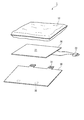
本発明のヒータ1は、図1に示すように、包囲体10と、発熱体20と、表皮体30とを備える。
As shown in FIG. 1, the
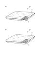
包囲体10は、図2に示すように、可撓性を有する袋体11に、20℃における熱伝導率が1.0W/(m・K)以上である伝熱性材料片を収容したものであり、包囲体10は全体として変形可能である。伝熱性材料としては、20℃における熱伝導率が1.0W/(m・K)以上であれば特に制限はなく、安価なものほど好ましく、鉄や銅、アルミニウム、あるいはそれらの合金が好ましい。
As shown in FIG. 2, the
伝熱性材料片の形状は、特に制限はなく、例えば、繊維状物12(図2(a))や粒状物13(図2(b))、あるいは繊維状物12と粒状物13との混合物などが挙げられる。
The shape of the heat conductive material piece is not particularly limited. For example, the fibrous material 12 (FIG. 2A) or the granular material 13 (FIG. 2B), or the mixture of the
繊維状物12は、伝熱性を確保しつつ、変形に追従できれば繊維長や繊維径には制限はないが、繊維が長いほど繊維同士が絡み合って伝熱しやすくなるため1〜500μmが好ましい。また、包囲体10に収容される繊維状物12のかさ密度は、0.01〜10g/cm3が好ましい。繊維量が多くなるほど包囲体10が厚くなり、被加熱部材の細かな形状に追従し難くなる。一方、繊維量が少なくなるほど包囲体10が薄くなり、変形しやすくなるが、発熱体20や表皮体30は可撓性を有するものの、包囲体10に比べると変形量は少ないため、包囲体10との間に隙間ができやすい。そこで、包囲体10に収容される繊維状物12のかさ密度は、0.1〜1.0g/cm3が適当である。
The
粒状物13は、その形状に特に制限はなく、球形である必要はなく、多面体や無定形、扁平体、円筒状であってもよい。また、粒状物13は、中実である必要はなく、中空にすることにより軽量化することができる。そして、変形した際に袋体11の内部で粒同士が接触し合えるように、個数や粒径が調整される。例えば、粒径は1〜10mmであればよい。その際、異なる形状や寸法の粒状物13を混合してもよい。
The shape of the
袋体11は、耐熱性を有する材料からなり、かつ、変形自在であるために可撓性を有する。袋体11としては、金属製の箔やシート、フィルム、メッシュ、ガラスファイバー、セラミックファイバー、シリカファイバー等といった無機繊維製クロスなどが挙げられる。また、変形による損傷や劣化を抑えるために、耐熱性の樹脂をコーティングして補強してもよい。尚、繊維状物12を収容する場合は、メッシュでは網目から突出したり、離脱することが考えられるため、金属箔や金属シート、金属フィルムを用いることが好ましい。また、粒状物13を収容する場合も、メッシュの網目から脱落しないように、粒径を考慮して目開きを調整する必要がある。袋体11の厚さは、特に制限はないが、0.01〜3mmであればよい。
The
また、包囲体10は、被加熱部材に装着した際に、変形して隙間を埋めるように、被加熱部材に装着したときにある程度の厚みを有する。具体的な厚さは用途に応じて設定することができるが、一般的な寸法や形状の配管や継手、バルブ等では、0.5〜3.0cmとすることにより、隙間を埋めることができる。
Further, the
発熱体20は、変形可能なように可撓性をすることが好ましく、更には広い面積を一度に加熱できるように加熱面21が面状であることが好ましい。具体的には、ヒータ線を耐熱性の布やリボンに縫合して一体化させた面状ヒータやリボンヒータ等を用いることができる。また、セラミックヒータを用いることもできる。尚、符合22は、外部電源(図示せず)に接続されるプラグである。
The
表皮体30は、可撓性を有する材料であれば特に制限はないが、例えばシリコーン樹脂、フッ素樹脂、ポリオレフィン樹脂、ポリエステル樹脂、塩化ビニル樹脂、ポリイミド樹脂等からなるシートや、ガラスファイバー、セラミックファイバー、シリカファイバー等といった無機繊維製クロスであればよい。表皮体30の厚さは特に制限はないが、0.1〜5mmであればよい。また、図示されるように、被加熱部材に装着した際に、装着状態を維持できるように両端縁に、面ファスナー31,32等を備えていてもよい。また、図示は省略するが、面ファスナーを用いずとも、ベルトを巻装して固定することもできる。尚、表皮体30は、全体を包囲できるように、包囲体10や発熱体20よりも幅広にする。
The
必要に応じて、発熱体20と表皮体30との間に、断熱材(図示せず)を介在させてもよい。こうした断熱材としては、無機繊維製シート、有機繊維製シート、樹脂発泡体とを使用でき、無機質繊維製シートは、ガラスファイバー、セラミックファイバー、シリカファイバー等の無機繊維材にニードル加工を施して、必要に応じてコロイダルシリカ、アルミナゾル、ケイ酸ソーダ等の無機質バインダーでシート状に形成させたものが好ましい。また、アラミド、ポリアミド、ポリイミド等の有機繊維製シートも使用できる。さらに、シリコーン樹脂、フッ素樹脂発泡体等の樹脂発泡体も使用できる。こうした断熱材の厚さは特に制限はないが、1〜30mm、3〜15mmであればよい。
If necessary, a heat insulating material (not shown) may be interposed between the
上記の如く構成されるヒータ1は、種々の形状の被加熱部材に装着することができる。その際、包囲体10は繊維状物12または粒状物13を収容した袋体11であり、ある程度の厚みがあるため、被加熱部材と発熱体20との隙間を埋めて効率良く加熱することが可能になる。
The
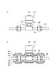
例えば、図3(a)に示すように、バルブ100は、本体部分101の両端にナット102を介して配管103が接続されるとともに、本体部分101には内部の弁部材の開閉を制御するアクチュエータ104が接続されており、複雑な形状を呈する。そのため、特許文献1をはじめとして一般的なヒータでバルブ100を包囲するように装着すると、本体部分101とナット102との間の空間(図中110で示す部分)や、本体部分101とアクチュエータ104との接続部分(図中111で示す部分)、ナット102とアクチュエータ104との間の空間(図中112で示す部分)に隙間ができる。しかし、図3(b)に示すように、本発明のヒータ1を用いると、包囲体10が変形してこれらの隙間110、111、112に入り込み、発熱体20からの熱を繊維状物12や粒状物13が伝熱して加熱効率を高める。
For example, as shown in FIG. 3A, the
また、包囲体10は、例えば、直径1インチ(25.4mm)以下といった細い配管に装着して使用することもできる。具体的には、直径6.0〜13.0mm、6.35〜12.7mm、6.35〜9.525mmといった細い配管に装着して使用することもできる。こういった比較的細い配管を加熱しようとする際には、特開2003−185086号公報に記載されるように、配管を均一に加熱するために、アルミニウムなど金属製で、中心に配管挿通用の貫通孔が形成された円筒体を貫通孔の軸線に沿って2等分してなる半筒体を一対、配管に装着する構成の配管加熱用被覆体(アルミブロックともいう)を用い、この配管加熱用被覆体を包囲するヒータからの熱を伝熱することで配管を加熱することが行われている。しかしながら、こうしたアルミブロックは配管に応じて設計、加工しなければならず、コスト高になってしまう。本発明のヒータ1によれば、包囲体10を配管に巻くことにより、包囲体10の柔軟性、弾力性により配管とヒータとの隙間を埋めることができるため、ある程度の幅を持って配管に対応できるので、配管ごとに設計、加工する必要がなく汎用的に使用できる。また、材料費も安くなるほか、軽量化を図ることができる。
The
上記では、包囲体10、発熱体20及び表皮体30を個別にしたが、図4に示すように、包囲体10、発熱体20及び表皮体30を積層して一体化してヒータ1とすることもできる。一体化することにより、被加熱部材への装着が一度ですみ、作業性が向上する。
In the above description, the
また、図示は省略するが、発熱体20と表皮体30とを一体化してもよく、表皮体30に発熱体20を埋め込むこともできる。また、発熱体20と表皮体30との間に断熱材を介在させてもよい。
Although not shown, the
尚、包囲体10は、本発明における伝熱部材に相当する。
The
1 ヒータ
10 包囲体(伝熱部材)
11 袋体
12 繊維状物
13 粒状物
20 発熱体
30 表皮体
1
11
Claims (3)
発熱体と、
20℃における熱伝導率が1.0W/(m・K)以上の伝熱性材料片を可撓性の袋体に収容してなり、全体として変形可能な包囲体と、
可撓性の表皮体とを備え、
包囲体で被加熱部材を覆い、包囲体の外側に発熱体を配置して全体を表皮材で被覆することを特徴とするヒータ。 A heater that surrounds and heats a heated member,
A heating element;
An envelopment body that is formed by accommodating a heat conductive material piece having a thermal conductivity at 20 ° C. of 1.0 W / (m · K) or more in a flexible bag body,
A flexible epidermis,
A heater characterized in that a member to be heated is covered with an envelope, a heating element is disposed outside the envelope, and the whole is covered with a skin material.
20℃における熱伝導率が1.0W/(m・K)以上の伝熱性材料片を可撓性の袋体に収容してなり、全体として変形可能であることを特徴とする伝熱部材。 A heat transfer member interposed between the heated member and the heating element,
A heat transfer member characterized in that a heat transfer material piece having a thermal conductivity at 20 ° C. of 1.0 W / (m · K) or more is accommodated in a flexible bag and is deformable as a whole.
Priority Applications (1)
| Application Number | Priority Date | Filing Date | Title |
|---|---|---|---|
| JP2012143415A JP5883354B2 (en) | 2012-06-26 | 2012-06-26 | Heater and heat transfer member |
Applications Claiming Priority (1)
| Application Number | Priority Date | Filing Date | Title |
|---|---|---|---|
| JP2012143415A JP5883354B2 (en) | 2012-06-26 | 2012-06-26 | Heater and heat transfer member |
Publications (2)
| Publication Number | Publication Date |
|---|---|
| JP2014007111A true JP2014007111A (en) | 2014-01-16 |
| JP5883354B2 JP5883354B2 (en) | 2016-03-15 |
Family
ID=50104642
Family Applications (1)
| Application Number | Title | Priority Date | Filing Date |
|---|---|---|---|
| JP2012143415A Active JP5883354B2 (en) | 2012-06-26 | 2012-06-26 | Heater and heat transfer member |
Country Status (1)
| Country | Link |
|---|---|
| JP (1) | JP5883354B2 (en) |
Cited By (3)
| Publication number | Priority date | Publication date | Assignee | Title |
|---|---|---|---|---|
| WO2015162524A1 (en) * | 2014-04-25 | 2015-10-29 | Bani-Asaf Inc. | Device to heat flexible hose connectors for transport vehicles |
| WO2017002241A1 (en) * | 2015-07-01 | 2017-01-05 | ニチアス株式会社 | Heater device and heating method using same for body to be heated |
| WO2023181649A1 (en) | 2022-03-24 | 2023-09-28 | 株式会社巴川製紙所 | Pipe heating structure, and pipe heating structure connecting body |
Citations (9)
| Publication number | Priority date | Publication date | Assignee | Title |
|---|---|---|---|---|
| JPH118049A (en) * | 1997-06-19 | 1999-01-12 | Mitsui Mining & Smelting Co Ltd | Molten metal heater and method of assembling the same |
| JP2003185086A (en) * | 2001-12-21 | 2003-07-03 | Satoru Murayama | Covering body for heating medium flow pipe |
| JP2004316864A (en) * | 2003-04-21 | 2004-11-11 | Tokyo Gijutsu Kenkyusho:Kk | Heater unit to be mounted on valve |
| JP2005106145A (en) * | 2003-09-30 | 2005-04-21 | Nichias Corp | Insulated heat insulation structure of piping and heat insulation tool kit |
| JP2005188677A (en) * | 2003-12-26 | 2005-07-14 | Nichias Corp | Piping heater |
| JP2006286315A (en) * | 2005-03-31 | 2006-10-19 | Nichias Corp | Covering member and heater device |
| JP2009168120A (en) * | 2008-01-15 | 2009-07-30 | Nitta Moore Co | Heating-heat insulating cover for pipe joint |
| JP2009275857A (en) * | 2008-05-15 | 2009-11-26 | Nichias Corp | Heat insulating body |
| JP2010038288A (en) * | 2008-08-06 | 2010-02-18 | Nichias Corp | Heat insulator |
-
2012
- 2012-06-26 JP JP2012143415A patent/JP5883354B2/en active Active
Patent Citations (9)
| Publication number | Priority date | Publication date | Assignee | Title |
|---|---|---|---|---|
| JPH118049A (en) * | 1997-06-19 | 1999-01-12 | Mitsui Mining & Smelting Co Ltd | Molten metal heater and method of assembling the same |
| JP2003185086A (en) * | 2001-12-21 | 2003-07-03 | Satoru Murayama | Covering body for heating medium flow pipe |
| JP2004316864A (en) * | 2003-04-21 | 2004-11-11 | Tokyo Gijutsu Kenkyusho:Kk | Heater unit to be mounted on valve |
| JP2005106145A (en) * | 2003-09-30 | 2005-04-21 | Nichias Corp | Insulated heat insulation structure of piping and heat insulation tool kit |
| JP2005188677A (en) * | 2003-12-26 | 2005-07-14 | Nichias Corp | Piping heater |
| JP2006286315A (en) * | 2005-03-31 | 2006-10-19 | Nichias Corp | Covering member and heater device |
| JP2009168120A (en) * | 2008-01-15 | 2009-07-30 | Nitta Moore Co | Heating-heat insulating cover for pipe joint |
| JP2009275857A (en) * | 2008-05-15 | 2009-11-26 | Nichias Corp | Heat insulating body |
| JP2010038288A (en) * | 2008-08-06 | 2010-02-18 | Nichias Corp | Heat insulator |
Cited By (8)
| Publication number | Priority date | Publication date | Assignee | Title |
|---|---|---|---|---|
| WO2015162524A1 (en) * | 2014-04-25 | 2015-10-29 | Bani-Asaf Inc. | Device to heat flexible hose connectors for transport vehicles |
| US10267448B2 (en) | 2014-04-25 | 2019-04-23 | Bani-Asaf Inc. | Device to heat flexible hose connectors for transport vehicles |
| WO2017002241A1 (en) * | 2015-07-01 | 2017-01-05 | ニチアス株式会社 | Heater device and heating method using same for body to be heated |
| KR20180025872A (en) | 2015-07-01 | 2018-03-09 | 니찌아스 카부시키카이샤 | HEATER APPARATUS AND HEATING METHOD USING THE SAME |
| JPWO2017002241A1 (en) * | 2015-07-01 | 2018-04-12 | ニチアス株式会社 | HEATER DEVICE AND METHOD OF HEATING A HEATED BODY USING THE SAME |
| TWI688306B (en) * | 2015-07-01 | 2020-03-11 | 日商霓佳斯股份有限公司 | Heating device and method for heating an object to be heated by using such heating device |
| US11215309B2 (en) | 2015-07-01 | 2022-01-04 | Nichias Corporation | Heating device and method of heating a heated object using the same |
| WO2023181649A1 (en) | 2022-03-24 | 2023-09-28 | 株式会社巴川製紙所 | Pipe heating structure, and pipe heating structure connecting body |
Also Published As
| Publication number | Publication date |
|---|---|
| JP5883354B2 (en) | 2016-03-15 |
Similar Documents
| Publication | Publication Date | Title |
|---|---|---|
| JP5602219B2 (en) | Jacket heater and mounting method thereof | |
| JP5800832B2 (en) | Jacket heater and heating method using jacket heater | |
| JP5883354B2 (en) | Heater and heat transfer member | |
| JP2004316864A (en) | Heater unit to be mounted on valve | |
| KR101318451B1 (en) | Rubber Lagging Material, Heating Apparatus and Manufacturing Method of Heating Apparatus | |
| KR101456813B1 (en) | Heating device | |
| KR101918492B1 (en) | Heating jacket | |
| JP2011220393A (en) | Heat insulating or heating covering member | |
| TWI688306B (en) | Heating device and method for heating an object to be heated by using such heating device | |
| KR101108577B1 (en) | Tape heater | |
| JP5851423B2 (en) | Heater and manufacturing method thereof | |
| JP4528099B2 (en) | Piping heating structure | |
| JP5348487B2 (en) | Thin plate heater structure | |
| KR102540130B1 (en) | Heater jacket for pipe using heat reflecting layer | |
| KR102276204B1 (en) | Temperature sensing device and fluid line heating jacket with the same | |
| TWM669530U (en) | Heating belt structure | |
| JP3179959U (en) | Piping heater | |
| JP2009174822A (en) | Fluid heating device | |
| KR200376038Y1 (en) | A mattress having heating system in bedstead | |
| KR20170072172A (en) | Heating apparatus with radiator panels | |
| JP5597910B2 (en) | Heating toilet seat and toilet device equipped with it | |
| JP2020092732A (en) | Sheet for keeping body warm | |
| JP2009302011A (en) | Heater | |
| JP2009095634A5 (en) |
Legal Events
| Date | Code | Title | Description |
|---|---|---|---|
| RD04 | Notification of resignation of power of attorney |
Free format text: JAPANESE INTERMEDIATE CODE: A7424 Effective date: 20140210 |
|
| A621 | Written request for application examination |
Free format text: JAPANESE INTERMEDIATE CODE: A621 Effective date: 20150515 |
|
| RD02 | Notification of acceptance of power of attorney |
Free format text: JAPANESE INTERMEDIATE CODE: A7422 Effective date: 20150515 |
|
| TRDD | Decision of grant or rejection written | ||
| A01 | Written decision to grant a patent or to grant a registration (utility model) |
Free format text: JAPANESE INTERMEDIATE CODE: A01 Effective date: 20160119 |
|
| A61 | First payment of annual fees (during grant procedure) |
Free format text: JAPANESE INTERMEDIATE CODE: A61 Effective date: 20160205 |
|
| R150 | Certificate of patent or registration of utility model |
Ref document number: 5883354 Country of ref document: JP Free format text: JAPANESE INTERMEDIATE CODE: R150 |
|
| R250 | Receipt of annual fees |
Free format text: JAPANESE INTERMEDIATE CODE: R250 |
|
| R250 | Receipt of annual fees |
Free format text: JAPANESE INTERMEDIATE CODE: R250 |
|
| R250 | Receipt of annual fees |
Free format text: JAPANESE INTERMEDIATE CODE: R250 |
|
| R250 | Receipt of annual fees |
Free format text: JAPANESE INTERMEDIATE CODE: R250 |
|
| R250 | Receipt of annual fees |
Free format text: JAPANESE INTERMEDIATE CODE: R250 |
|
| R250 | Receipt of annual fees |
Free format text: JAPANESE INTERMEDIATE CODE: R250 |
|
| R250 | Receipt of annual fees |
Free format text: JAPANESE INTERMEDIATE CODE: R250 |
|
| R250 | Receipt of annual fees |
Free format text: JAPANESE INTERMEDIATE CODE: R250 |