JP2014007745A - Power control in lte advanced heterogeneous network - Google Patents
Power control in lte advanced heterogeneous network Download PDFInfo
- Publication number
- JP2014007745A JP2014007745A JP2013131761A JP2013131761A JP2014007745A JP 2014007745 A JP2014007745 A JP 2014007745A JP 2013131761 A JP2013131761 A JP 2013131761A JP 2013131761 A JP2013131761 A JP 2013131761A JP 2014007745 A JP2014007745 A JP 2014007745A
- Authority
- JP
- Japan
- Prior art keywords
- base station
- prbs
- transmission power
- pico
- macro
- Prior art date
- Legal status (The legal status is an assumption and is not a legal conclusion. Google has not performed a legal analysis and makes no representation as to the accuracy of the status listed.)
- Pending
Links
Images


Classifications
-
- H—ELECTRICITY
- H04—ELECTRIC COMMUNICATION TECHNIQUE
- H04W—WIRELESS COMMUNICATION NETWORKS
- H04W52/00—Power management, e.g. Transmission Power Control [TPC] or power classes
- H04W52/04—Transmission power control [TPC]
- H04W52/18—TPC being performed according to specific parameters
- H04W52/24—TPC being performed according to specific parameters using SIR [Signal to Interference Ratio] or other wireless path parameters
- H04W52/243—TPC being performed according to specific parameters using SIR [Signal to Interference Ratio] or other wireless path parameters taking into account interferences
- H04W52/244—Interferences in heterogeneous networks, e.g. among macro and femto or pico cells or other sector / system interference [OSI]
-
- H—ELECTRICITY
- H04—ELECTRIC COMMUNICATION TECHNIQUE
- H04B—TRANSMISSION
- H04B17/00—Monitoring; Testing
- H04B17/30—Monitoring; Testing of propagation channels
- H04B17/309—Measuring or estimating channel quality parameters
- H04B17/345—Interference values
Landscapes
- Engineering & Computer Science (AREA)
- Computer Networks & Wireless Communication (AREA)
- Signal Processing (AREA)
- Mobile Radio Communication Systems (AREA)
Abstract
Description
本出願の実施形態は、全体として、通信ネットワークに関し、より具体的には、異種通信ネットワークにおける電力制御スキームに関する。 Embodiments of the present application relate generally to communication networks, and more specifically to power control schemes in heterogeneous communication networks.
ロング・ターム・エボリューション・アドバンスト(LTE−A)ネットワークは、基地局(BS)の多様な集合を異種混合で配備することによってセルサイズを低減することにより、スペクトル効率を改善するように設計されている。異種セルラーネットワークでは、マクロBSは、高い送信電力(例えば、46dBm)で規則的かつ計画的な方式で配備され、オーバーレイさせたピコBSは、比較的低い送信電力(例えば、30dBm)で狭いカバレッジ(例えば、マクロセルの端部)に配備される。オーバーレイさせたBSの配備は、カバレッジを改善するとともに、スペクトルの空間再利用を増大させることによって容量利得をもたらすことができる。 Long Term Evolution Advanced (LTE-A) networks are designed to improve spectral efficiency by reducing cell size by deploying diverse sets of base stations (BS) in a heterogeneous mix Yes. In heterogeneous cellular networks, macro BSs are deployed in a regular and planned manner with high transmit power (eg, 46 dBm), and overlaid pico BSs have narrow coverage (with a relatively low transmit power (eg, 30 dBm)). For example, it is deployed at the end of the macro cell. Overlaid BS deployments can provide capacity gain by improving coverage and increasing spectral spatial reuse.
LTE−Aのリリース10(Rel−10)では、ピコユーザ機器(UE)に対する干渉を低減するため、マクロBSは、オールモースト・ブランク・サブフレーム(ABS)として知られている特定のサブフレームをミュートすることができる。ABSでは、ほとんどのリソースエレメント(RE)がブランクであり、少量のREのみが何らかのシステム情報(例えば、セル固有基準信号および同期信号)を保有する。ピコUEは、それによって受ける干渉が少なくなり、マクロBSがABSを送信する際のより高いデータ転送率を達成することができる。 In Release 10 (Rel-10) of LTE-A, in order to reduce interference to the pico user equipment (UE), the macro BS mutes a specific subframe known as an all-most blank subframe (ABS). can do. In ABS, most resource elements (REs) are blank, and only a small amount of REs carry some system information (eg, cell specific reference signals and synchronization signals). The pico UE receives less interference thereby and can achieve a higher data rate when the macro BS transmits the ABS.
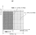
LTE−Aシステムでは、無線リソースはREおよび物理リソースブロック(PRB)に分割される。図1は、ロング・ターム・エボリューション/ロング・ターム・エボリューション・アドバンスト(LTE/LTE−A)の構造例を示す。 In the LTE-A system, radio resources are divided into REs and physical resource blocks (PRBs). FIG. 1 shows an example of a structure of Long Term Evolution / Long Term Evolution Advanced (LTE / LTE-A).
図1では、LTE/LTE−Aサブフレームの構造は、時間ドメインおよび周波数ドメイン内で示される。各サブフレームは2つの時間スロットに分割され、各時間スロットは、(通常のサイクリック・プレフィックス長さに対して)7つの直交周波数分割多重(OFDM)シンボルを含んでいる。OFDMシンボル長さおよびサブキャリア帯域幅を有する各グリッドはREと呼ばれる。PRBは、時間ドメイン内の時間スロットと同じ長さを有し、周波数ドメイン内の12個のサブキャリアに及ぶ。 In FIG. 1, the structure of the LTE / LTE-A subframe is shown in the time domain and the frequency domain. Each subframe is divided into two time slots, and each time slot contains seven orthogonal frequency division multiplexed (OFDM) symbols (for normal cyclic prefix length). Each grid with OFDM symbol length and subcarrier bandwidth is called an RE. The PRB has the same length as the time slot in the time domain and spans 12 subcarriers in the frequency domain.
LTE−Aネットワークは異種ネットワークであり、単位面積当たりのスペクトル効率を改善できるマクロBSおよびピコBSが共存している。しかし、かかるマクロ・ピコ配備において、ピコUEの中でも特にセル端にあるものは、隣接するマクロBSによる強い干渉を受ける傾向がある。 The LTE-A network is a heterogeneous network, and a macro BS and a pico BS that can improve spectral efficiency per unit area coexist. However, in such a macro-pico deployment, among the pico UEs, particularly those located at the cell edge, tend to be subjected to strong interference by adjacent macro BSs.
例示の実施形態の態様は、少なくとも1つのマクロBSと関連付けられた複数のPRBの少なくとも1つの電力割付けパターンに基づいて、UEのスケジューリングに対する干渉分布情報を生成し、干渉分布情報に基づいて、ピコBSと関連付けられた少なくとも1つのUEのスケジューリングを行うように構成された中央処理装置(CPU)を含む、ピコUSを含んでもよい。 Aspects of the exemplary embodiments generate interference distribution information for UE scheduling based on at least one power allocation pattern of a plurality of PRBs associated with at least one macro BS, and based on the interference distribution information, A pico US may be included, including a central processing unit (CPU) configured to perform scheduling of at least one UE associated with the BS.
例示の実施形態のさらなる態様は、少なくとも1つの被害を受けるピコUEのトラフィック負荷に基づいて、マクロBSによって管理される複数のPRBに対する電力割付けパターンを決定するように構成されたCPUと、少なくとも1つの被害を受けるUEと関連付けられた少なくとも1つのピコBSに電力割付けパターンを送信するように構成されたインターフェースとを含む、マクロBSを含んでもよい。 A further aspect of the exemplary embodiment includes a CPU configured to determine a power allocation pattern for a plurality of PRBs managed by a macro BS based on the traffic load of at least one victimized pico UE, and at least one And a macro BS including an interface configured to transmit a power allocation pattern to at least one pico BS associated with one victim UE.
例示の実施形態のさらなる態様は、少なくとも1つのマクロBSと関連付けられた複数のPRBの少なくとも1つの電力割付けパターンに基づいて、UEのスケジューリングに対する干渉分布情報を生成し、干渉分布情報に基づいて、少なくとも1つのピコBSと関連付けられた少なくとも1つのUEのスケジューリングを行うように構成された、少なくとも1つのピコBSと、少なくとも1つの被害を受けるピコUEのトラフィック負荷に基づいて、少なくとも1つのマクロBSによって管理される複数のPRBに対する少なくとも1つの電力割付けパターンを決定し、少なくとも1つの被害を受けるUEと関連付けられた少なくとも1つのピコBSに電力割付けパターンを送信するように構成された、少なくとも1つのマクロBSとを含む、システムを含んでもよい。 A further aspect of the exemplary embodiment is to generate interference distribution information for UE scheduling based on at least one power allocation pattern of a plurality of PRBs associated with at least one macro BS, and based on the interference distribution information, At least one macro BS based on the traffic load of at least one pico BS and at least one victim pico UE configured to schedule at least one UE associated with the at least one pico BS. At least one power allocation pattern for a plurality of PRBs managed by the at least one pico BS associated with the at least one victim UE and determining the at least one power allocation pattern Including macro BS It may include a system.
本発明によれば、マクロBSとピコUEとの間の干渉を低減できる。 According to the present invention, it is possible to reduce interference between a macro BS and a pico UE.
以下の例示の実施形態の詳細な説明では添付図面を参照するが、それら添付図面では、同一の機能的要素は同様の番号によって指定される。上述の添付図面は、例示の実施形態および実現例を限定目的ではなく例証目的で示すものである。これらの実現例は、当業者が本発明を実施できるように十分に詳細に記載されており、他の実現例が利用されてもよく、また例示の実施形態の範囲および趣旨から逸脱することなく、様々な要素の構造上の変化および/または置換が行われてもよいことを理解されたい。従って、以下の詳細な説明は限定的な意味で解釈すべきでない。 In the following detailed description of exemplary embodiments, reference is made to the accompanying drawings, in which identical functional elements are designated with like numerals. The accompanying drawings described above illustrate exemplary embodiments and implementations for purposes of illustration and not limitation. These implementations have been described in sufficient detail to enable those skilled in the art to practice the invention, other implementations may be utilized, and without departing from the scope and spirit of the illustrated embodiments. It should be understood that structural changes and / or substitutions of various elements may be made. The following detailed description is, therefore, not to be construed in a limiting sense.
一例では、LTE−A異種ネットワークにおけるピコUEに対するマクロBSの干渉を低減するための電力制御スキームが提案される。提案される方法では、ピコBSは、マクロBSによる被害を受けるUEのトラフィック負荷を報告するマクロBSの集合を選択する。1つまたは複数のピコBSからのトラフィック負荷情報に基づいて、マクロBSは、PRB全体にわたるその電力割付けを決定し、隣接するピコBSと電力割付けパターンを共有する。ピコBSは、1つまたは複数のマクロBSから受信した電力割付けパターンに基づいて、関連するUEのデータ送信のスケジューリングを行う。 In one example, a power control scheme is proposed to reduce macro BS interference for pico UEs in LTE-A heterogeneous networks. In the proposed method, the pico BS selects a set of macro BSs reporting the traffic load of UEs that are damaged by the macro BS. Based on the traffic load information from one or more pico BSs, the macro BS determines its power allocation across the PRB and shares power allocation patterns with neighboring pico BSs. The pico BS schedules data transmission for the associated UE based on the power allocation pattern received from one or more macro BSs.
LTE−A異種ネットワークのダウンリンクの場合、ピコUE(例えば、ピコセルと関連付けられたUE)は、マクロBSの送信電力が高いことにより、隣接するマクロBSから強い干渉を受ける。ピコUE、特にセル端にあるもののスループットを改善するため、ピコUEに対するマクロBSの干渉を制御する電力制御スキームが必要とされている。例示の実施形態は、ピコUEのセル平均およびセル端のスループットを改善することができる、マクロBSとピコUEとの間の干渉を低減する電力制御スキームを対象とする。 In the case of a downlink of an LTE-A heterogeneous network, a pico UE (eg, a UE associated with a pico cell) receives strong interference from neighboring macro BSs due to the high transmission power of the macro BS. In order to improve the throughput of pico UEs, particularly those at the cell edge, there is a need for a power control scheme that controls macro BS interference for pico UEs. Exemplary embodiments are directed to a power control scheme that reduces interference between a macro BS and a pico UE, which can improve the cell average and cell edge throughput of the pico UE.
例示の実施形態では、ピコBSは、被害を受けるUEのトラフィック負荷をピコBSが報告するマクロBSの集合を選択する。1つまたは複数のピコBSからのトラフィック負荷情報に基づいて、マクロBSは、物理リソースブロック(PRB)全体にわたるその電力割付けを決定し、隣接するピコBSと電力割付けパターンを共有する。ピコBSは、1つまたは複数のマクロBSから受信した電力割付けパターン(1つもしくは複数)に基づいて、関連するUEのデータ送信のスケジューリングを行う。 In the exemplary embodiment, the pico BS selects a set of macro BSs for which the pico BS reports the traffic load of the affected UE. Based on traffic load information from one or more pico BSs, the macro BS determines its power allocation across physical resource blocks (PRBs) and shares power allocation patterns with neighboring pico BSs. The pico BS schedules the data transmission of the associated UE based on the power allocation pattern (s) received from one or more macro BSs.
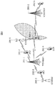
図2は、例示の一実施形態による異種ネットワークを示す。図2に示される異種セルラーネットワーク例には、ピコBS200−1、200−2、マクロBS201−1、201−2、およびUE 202−1、202−2、202−3、202−4、202−5の混合が存在する。マクロBSおよびピコBSは共同してエリア内の複数のUEに役立つ。ピコBSと関連付けられたセル端にあるUEは、マクロBSから強い干渉を受けることがある。例えば、UE1 202−1はピコBS1 200−1と関連付けられるが、マクロBS1 201−1およびマクロBS2 201−2から強い干渉を受けることがあり、UE3 202−3はピコBS2 200−2と関連付けられるが、マクロBS1 201−1から強い干渉を受けることがある。例示の実施形態は、マクロBSからピコUEへの干渉を低減できるようにして、マクロBSおよびピコBSに対して実現することができる。 FIG. 2 illustrates a heterogeneous network according to an example embodiment. Examples of the heterogeneous cellular network shown in FIG. 2 include pico BSs 200-1, 200-2, macro BSs 201-1, 201-2, and UEs 202-1, 202-2, 202-3, 202-4, 202-. There are 5 mixtures. The macro BS and the pico BS jointly serve multiple UEs in the area. A UE at the cell edge associated with a pico BS may experience strong interference from the macro BS. For example, UE1 202-1 is associated with pico BS1 200-1, but may receive strong interference from macro BS1 201-1 and macro BS2 201-2, and UE3 202-3 is associated with pico BS2 200-2. May receive strong interference from the macro BS1 201-1. The exemplary embodiments can be implemented for macro BSs and pico BSs, allowing interference from macro BSs to pico UEs to be reduced.
図3は、例示の一実施形態によるマクロBSのハードウェア構成のブロック図を示す。ブロック図に示されるようなハードウェア構成は、任意のマクロBS(例えば、図2に示されるようなマクロBS1 201−1およびマクロBS2 201−2など)で実現されてもよい。マクロBSは、X2インターフェース301と、中央処理装置(CPU)302と、無線周波数(RF)モジュール303と、ベースバンド・プロセッサ304と、メモリ305とを含む構成300を使用してもよい。CPU 302は、X2インターフェース301からの入力に基づいてPRB全体にわたる電力割付けを決定し、メモリ305内の電力割付けテーブルを更新する。さらに、CPU 302はまた、RFモジュールの出力信号が選択された電力割付けパターンに従うように、マクロUEのデータ送信のスケジューリングを行い、ベースバンド・プロセッサ304およびRFモジュール303を制御するように構成されてもよい。
FIG. 3 shows a block diagram of a hardware configuration of a macro BS according to an exemplary embodiment. The hardware configuration as shown in the block diagram may be realized by an arbitrary macro BS (for example, macro BS1 201-1 and macro BS2 201-2 as shown in FIG. 2). The macro BS may use a
ベースバンド・プロセッサ304は、マクロBSに対するベースバンド動作を扱うように構成される。ベースバンド動作は、ターボ符号化、レートマッチング、変調、層マッピング、MIMOプレコーディング、IFFT、およびLTE/LTE−A規格で利用される他の動作を含んでもよい。
RFモジュール303は、マクロBSに対するRF動作を扱うように構成される。RFモジュールは、ベースバンド・プロセッサから供給されたベースバンド信号をRF信号に変換し、次に1つまたは複数のアンテナを通してRF信号を送信する。
The
メモリ305は、電力割付けテーブルを格納するように構成される。電力割付けテーブルの内容に関するさらなる詳細については、図12の説明で後述する。
The
X2インターフェース301は、隣接するピコBSとの情報交換を扱うように構成される。具体的には、マクロBSは、X2インターフェースを介して隣接するピコBSからトラフィック負荷情報を受信する。受信情報に基づいて、マクロBSはその電力割付けを決定し、X2インターフェースを介して電力割付けパターンを隣接するピコBSに通知する。上述の手順の詳細については、図8の説明において説明する。
The
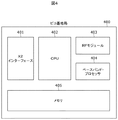
図4は、例示の一実施形態によるピコBSのハードウェア構成のブロック図を示す。ブロック図に示されるようなハードウェア構成は、任意のピコBS(例えば、図2に示されるようなピコBS1 200−1およびピコBS2 200−2など)で実現されてもよい。ピコBSは、X2インターフェース401と、中央処理装置(CPU)402と、無線周波数(RF)モジュール403と、ベースバンド・プロセッサ404と、メモリ405とを含む構成400を使用してもよい。CPU 402は、1つまたは複数のマクロBSから受信した電力割付けパターン(1つもしくは複数)に基づいて、各PRBに対する干渉レベルを推定し、メモリ405内の干渉分布テーブルを更新するように構成される。さらに、CPU 402は、メモリ405内の干渉分布テーブルに基づいてピコUEのスケジューリングを行うように構成される。CPU 402はまた、スケジューリングされたUEに対してデータを送信するようにベースバンド・プロセッサ404およびRFモジュール403を制御する。
FIG. 4 shows a block diagram of a hardware configuration of a pico BS according to an example embodiment. The hardware configuration as shown in the block diagram may be realized by an arbitrary pico BS (for example, pico BS1 200-1 and pico BS2 200-2 as shown in FIG. 2). The pico BS may use a
ベースバンド・プロセッサ404は、ピコBSに対するベースバンド動作を扱うように構成される。ピコBSに対するベースバンド動作は、マクロBSに対するものと類似している。
RFモジュール403は、ピコBSに対するRF動作を扱うように構成される。ピコBSに対するRF動作は、マクロBSに対するものと類似している。
The
メモリ405は、干渉分布テーブルを格納するように構成され、その詳細については図13の説明で後述する。
The
X2インターフェース401は、隣接するピコBSとの情報交換を扱うように構成される。具体的には、ピコBSは、そのトラフィック負荷情報をX2インターフェースを介して隣接するマクロBSに送信するので、それらマクロBSは、図7の説明でさらに詳細に記載するように、それらの電力割付けパターンを決定することができる。隣接するマクロBSから電力割付けパターンを受信した後、ピコBSは、図10の説明でさらに詳細に記載するように、干渉分布を推定し、そのスケジューラを適宜調節する。
The
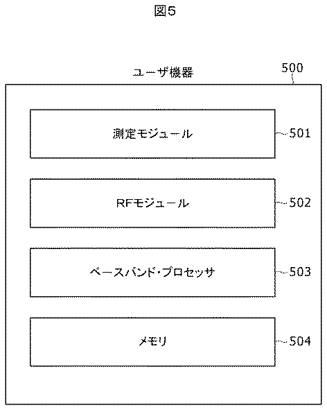
図5は、LTE−AシステムにおけるUEのハードウェア構成のブロック図を示す。ブロック図に示されるようなハードウェア構成は、LTE−Aシステムの任意のUE(例えば、図2に示されるようなUE 202−1、202−2、202−3、202−4、202−5)で実現されてもよい。UEは、測定モジュール501と、無線周波数(RF)モジュール502と、ベースバンド・プロセッサ503と、メモリ504とを含む構成500を使用してもよい。測定モジュール501は、隣接するマクロBSおよびピコBSからの基準信号受信電力(RSRP)を測定し、測定結果を関連するBSに送信するように構成される。ベースバンド・プロセッサ503は、UEに対するベースバンド動作を扱うように構成される。RFモジュール502は、UEに対するRF動作を扱うように構成される。メモリ504は、受信データ・パケットを格納する。
FIG. 5 shows a block diagram of the hardware configuration of the UE in the LTE-A system. The hardware configuration as shown in the block diagram allows any UE in the LTE-A system (eg, UEs 202-1, 202-2, 202-3, 202-4, 202-5 as shown in FIG. 2). ). The UE may use a
図6は、例示の一実施形態によるシステムのフローチャートを示す。600で、各UEは、隣接するBSからのRSRPを測定し、それに関連するBSに測定レポートを送信する。601で、関連するUEから測定レポートを受信した後、各ピコBSは、近隣にある各マクロBSについて被害を受けるUEを特定し、602で被害を受けるUEのトラフィック負荷をピコBSが報告するマクロBSの集合を決定する。603で、ピコBSは、X2インターフェースを通して、報告対象の集合内の各マクロBSにトラフィック負荷情報を送信する。被害を受けるUEに対するトラフィック負荷情報は、被害を受けるUEに割り当てられるPRBの数、パケット到着率、またはスループットを含んでもよい。604で、1つまたは複数のピコBSからのトラフィック負荷レポートに基づいて、マクロBSは電力割付けパターンを決定する。604で、マクロBSは、UEのスケジューリングのため、(X2インターフェースを介して)1つまたは複数のピコBSとパターンを共有する。一方で、マクロBSは、その電力割付けパターンに基づいて、自身のUEのデータ送信のスケジューリングを行ってもよい。605で、ピコBSは、受信した電力割付けパターンに基づいて、関連するUEに対するデータ送信スケジュールを生成する。606で、ピコBSは、データ送信スケジュールに基づいて、関連するUEにデータ・パケットを送信するように命令する。 FIG. 6 shows a flow chart of a system according to an exemplary embodiment. At 600, each UE measures RSRP from neighboring BSs and sends a measurement report to the associated BS. After receiving the measurement report from the associated UE at 601, each pico BS identifies the affected UE for each neighboring macro BS, and the macro at which the pico BS reports the traffic load of the affected UE at 602. A set of BSs is determined. At 603, the pico BS transmits traffic load information to each macro BS in the report target set through the X2 interface. The traffic load information for the damaged UE may include the number of PRBs allocated to the damaged UE, the packet arrival rate, or the throughput. At 604, the macro BS determines a power allocation pattern based on traffic load reports from one or more pico BSs. At 604, the macro BS shares a pattern with one or more pico BSs (via the X2 interface) for UE scheduling. On the other hand, the macro BS may schedule data transmission of its own UE based on the power allocation pattern. At 605, the pico BS generates a data transmission schedule for the associated UE based on the received power allocation pattern. At 606, the pico BS instructs the associated UE to transmit data packets based on the data transmission schedule.
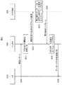
図7は、例示の一実施形態による、ピコBSがそのトラフィック負荷情報を隣接するマクロBSに報告する際のフローチャートを示す。ピコBSは、関連するUEから測定レポートを受信する。図4のハードウェア構成例400に関して言及する。700で、CPUは関連するUEから測定レポートを受信する。受信した測定レポートに基づいて、CPUは、701と702で示されるようにメモリ405内のRSRP測定テーブルを更新する。
FIG. 7 shows a flow chart when a pico BS reports its traffic load information to an adjacent macro BS according to one exemplary embodiment. The pico BS receives a measurement report from the associated UE. Reference is made to the
測定テーブルおよび被害を受けるUEに対する閾値に基づいて、CPU 402は、特定のマクロBSについて被害を受けるUEを特定することができる。マクロBSについて被害を受けるUEの数が閾値を上回る場合、CPU 402は、703で、トラフィック負荷を報告する報告対象の集合にマクロBSを含めてもよい。704で、報告対象の集合内のマクロBSのIDがX2インターフェース401に送信されて、それらのマクロBSとの接続が確立される。X2インターフェース401は、705で報告対象の集合内のマクロBSへのリンクを確立し、706でX2接続を要求する。マクロBSへの接続が確立されると、ピコBSは、このマクロBSの被害を受けるUEに関するトラフィック負荷全体を提供するトラフィック負荷レポートを送信する。例えば、図2のピコBS1 200−1は、UE1 202−1およびUE2 202−2の合計のトラフィック負荷をマクロBS1 201−1に報告するようになる。
Based on the measurement table and the threshold for the victim UE, the
図11は、ピコBS(この例では、図2に示されるようなピコBS1 200−1)のRSRP測定テーブル例であるが、RSRP値の例は例証目的で与えられるものであり、被害を受けるUEの閾値例は10に設定されている。 FIG. 11 is an example of an RSRP measurement table of a pico BS (in this example, pico BS1 200-1 as shown in FIG. 2), but an example of an RSRP value is given for illustrative purposes and suffers damage. An example threshold for the UE is set to 10.
図8は、例示の一実施形態によるマクロBSのフローチャートを示す。800で、マクロBSは、X2インターフェース301を介して1つまたは複数のピコBSからトラフィック負荷情報を受信する。トラフィック負荷レポートに基づいて、CPU 302は、801および802で示されるように、電力割付けパターンを決定し、メモリ305内の電力割付けテーブルを適宜更新する。さらに、CPUは電力割付けパターンをRFモジュールに送信し、それにより、RFモジュールの出力信号はパターンに従う。電力割付けパターンはまた、803で示されるように、1つまたは複数のピコBSに送信されてもよい。電力割付けパターンに基づいて、CPU 302は、804で示されるように、マクロBSと関連付けられるUEのスケジューリングを行う。次に、スケジューリングされたUEそれぞれに割り当てられたPRBインデックスが、805および806でそれぞれ示されるように、ベースバンド処理のためにベースバンド・プロセッサ304に送信される。その後、807および808でそれぞれ示されるように、ベースバンド信号はRF処理のためにRFモジュール303に送信される。
FIG. 8 shows a flowchart of a macro BS according to an example embodiment. At 800, the macro BS receives traffic load information from one or more pico BSs via the
上述の例では、同じPRB内のREの送信電力は同じになるように設定される。しかし、異なるPRBの送信電力は異なっていてもよい。図9(a)〜9(d)は、例示的な一実施形態による、時間ドメインおよび周波数ドメイン内の電力割付けパターンの例を示す。図9(a)〜9(d)の例は、10個のサブフレームおよび1.4MHzの帯域幅を有するLTE−Aフレームのものであり、所与のPRBおよびサブフレームに対する送信電力を示している。例の列は、サブフレーム・インデックス、即ち時間ドメイン内の対応するサブフレームを示す。例の行は、PRBインデックス、即ち対応するPRBの送信電力を示す。電力割付けパターンは様々な構造を有する。 In the above example, the transmission power of REs in the same PRB is set to be the same. However, the transmission power of different PRBs may be different. FIGS. 9 (a) -9 (d) show examples of power allocation patterns in the time domain and frequency domain, according to an illustrative embodiment. The example of FIGS. 9 (a) -9 (d) is for an LTE-A frame with 10 subframes and a bandwidth of 1.4 MHz, showing the transmit power for a given PRB and subframe. Yes. The example column shows the subframe index, ie the corresponding subframe in the time domain. The example row shows the PRB index, ie the transmission power of the corresponding PRB. The power allocation pattern has various structures.
各PRBに対する送信電力は、デフォルト設定として使用される第1の送信電力、第1の送信電力よりも低い(例えば、第1の送信電力の特定の割合)第2の送信電力、およびゼロ送信電力または送信電力なしという、3つの値で構成することができる。 The transmission power for each PRB is a first transmission power that is used as a default setting, a second transmission power that is lower than the first transmission power (eg, a specific percentage of the first transmission power), and a zero transmission power. Alternatively, it can be configured with three values of no transmission power.
例えば、あるPRBが第1の送信電力で構成される場合、同じサブフレーム内のPRBは第1の送信電力で構成されてもよい。 For example, when a certain PRB is configured with the first transmission power, PRBs in the same subframe may be configured with the first transmission power.
あるPRBが第2の送信電力で構成される場合、同じ行内のPRB(第1の送信電力構成を有するPRBを除く)は第2の送信電力で構成されてもよい。 When a certain PRB is configured with the second transmission power, PRBs in the same row (excluding PRBs having the first transmission power configuration) may be configured with the second transmission power.
あるPRBが送信電力なしで構成される場合、同じ行内のPRB(第1の送信電力で構成されたPRBを除く)は送信電力なしで構成されてもよい。 When a certain PRB is configured without transmission power, PRBs in the same row (excluding PRB configured with the first transmission power) may be configured without transmission power.
複数の電力割付けパターンが事前定義され、メモリ内のテーブルに格納されてもよい。図12は、電力割付けパターンを記述するのに2つのビットマップが使用される、図9(a)〜9(d)に示されるような4つの電力割付けパターンに基づいたかかるテーブルの一例を示す。下記のテーブルにおいて、電力割付けパターン・インデックス1、2、3、および4はそれぞれ、図9(a)、9(b)、9(c)、および9(d)に対応する。
Multiple power allocation patterns may be predefined and stored in a table in memory. FIG. 12 shows an example of such a table based on four power allocation patterns as shown in FIGS. 9 (a) -9 (d), where two bitmaps are used to describe the power allocation pattern. . In the table below, power
具体的には、第1のビットマップは、第1の送信電力で構成されたPRBの位置(サブフレーム)を示す10ビットを有し、第2のビットマップは、第2の送信電力で構成されたPRBの位置(周波数帯)を示す。合計の帯域幅に応じて、第2のビットマップの長さは変動することがある。例えば、図9(b)に対する2つのビットマップは以下のように与えられる。 Specifically, the first bitmap has 10 bits indicating the position (subframe) of the PRB configured with the first transmission power, and the second bitmap is configured with the second transmission power. The position (frequency band) of the assigned PRB is shown. Depending on the total bandwidth, the length of the second bitmap may vary. For example, two bitmaps for FIG. 9B are given as follows:
第1のビットマップ:0110011100。ここで、「1」は、対応するサブフレーム(列)内のPRBが第1の送信電力で構成されていることを表す。 First bitmap: 0110011100. Here, “1” indicates that the PRB in the corresponding subframe (column) is configured with the first transmission power.
第2のビットマップ:010101。ここで、「1」は、対応する周波数帯(行)内のPRBが第2の送信電力で構成されていることを表す。 Second bitmap: 010101. Here, “1” represents that the PRB in the corresponding frequency band (row) is configured with the second transmission power.
固有のミューティング比は各電力割付けパターンと関連付けられるが、これはPz+(1−α)Prとして定義され、式中、PrおよびPzはそれぞれ、第2の送信電力を有するPRBおよび送信電力なしのPRBの割合であり、αは、第2の送信電力の値と第1の送信電力の値との間の比である。 A unique muting ratio is associated with each power allocation pattern, which is defined as P z + (1−α) P r , where P r and P z are each PRBs having a second transmit power. And the ratio of PRB without transmission power, and α is the ratio between the value of the second transmission power and the value of the first transmission power.
次に、1つまたは複数のピコBSから受信したトラフィック負荷情報に基づいて、電力割付けテーブルから電力割付けパターンが選択される。マクロBSがM個のピコBSからトラフィック負荷レポートを受信し、ピコBSmのトラフィック負荷がTmであると仮定して、マクロBSのCPUは次の基準値((1)式)を計算する。 Next, a power allocation pattern is selected from the power allocation table based on traffic load information received from one or more pico BSs. Assuming that the macro BS receives traffic load reports from M pico BSs and the traffic load of the pico BS m is T m , the macro BS CPU calculates the following reference value (equation (1)). .
(1)式中、T0はマクロBSのトラフィック負荷、βmはピコBSmのシステムパラメータであり、((2)式)のとおりである。 In Equation (1), T 0 is a traffic load of the macro BS, β m is a system parameter of the pico BS m , and is as shown in Equation (2).
次に、マクロBSのCPUは、ミューティング比が上述の基準値に最も近い電力割付けパターンを選択し、メモリ内における選択されたパターンのフィールド「アクティブ」を「はい」に設定することによって(残りのパターンのフィールド「アクティブ」は自動的に「いいえ」に設定される)、電力割付けテーブルを更新する。 Next, the CPU of the macro BS selects the power allocation pattern whose muting ratio is closest to the above-mentioned reference value, and sets the field “active” of the selected pattern in the memory to “yes” (the rest Field "active" is automatically set to "no"), and the power allocation table is updated.
マクロBSのCPUは、選択された電力割付けパターンに基づいて、次のように、関連するUEのデータ送信のスケジューリングを行う。UEは、それらのRSRPに基づいて、RSRPが事前定義した閾値を上回るセル中心のUEと、RSRPが事前定義した閾値を下回るセル端のUEとの2つの群に分割される。マクロBSのCPUは、第2の送信電力を有するPRB全体に対してのみセル中心のUEのスケジューリングを行う。第1の送信電力を有するPRBについては、マクロBSのCPUは、2つの群からのUEのスケジューリングを行う。スケジューリングされたUEそれぞれに割り当てられたPRBインデックスおよびアクティブな電力割付けパターンは、ベースバンド・プロセッサおよびRFモジュールに渡され、それにより、RFモジュールからの出力信号は選択された電力割付けパターンに従う。選択された電力割付けパターンに対する2つのビットマップおよび第2の送信電力の値は、マクロBSとのX2接続を有する1つまたは複数のピコBSに送信される。 Based on the selected power allocation pattern, the CPU of the macro BS schedules the data transmission of the associated UE as follows. Based on their RSRP, the UEs are divided into two groups: cell-centric UEs where RSRP exceeds a predefined threshold and cell-edge UEs where RSRP falls below a predefined threshold. The CPU of the macro BS schedules the cell-centered UE only for the entire PRB having the second transmission power. For PRBs having first transmission power, the macro BS CPU schedules UEs from two groups. The PRB index assigned to each scheduled UE and the active power allocation pattern are passed to the baseband processor and the RF module so that the output signal from the RF module follows the selected power allocation pattern. The two bitmaps and the second transmit power value for the selected power allocation pattern are transmitted to one or more pico BSs that have an X2 connection with the macro BS.
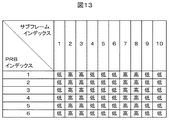
図10は、例示の一実施形態による、ピコBSが隣接するマクロBSから電力割付けパターンを受信した後の動作のフローチャートを示す。図10に示されるようなフローチャートは、1つまたは複数のマクロBSからの電力割付けパターンの受信および処理に関するものである。X2インターフェース401は、1000で示されるように、1つまたは複数のマクロBSから電力割付けパターンを受信し、それらをCPU 402に転送する。CPU 402は、1001および1002で示されるように、受信した電力割付けパターンに基づいてメモリ405内の干渉分布テーブルを更新する。干渉分布テーブルの一例が図13で与えられるが、ここで、「高」および「低」は、所与のPRBおよび所与のサブフレームを含む状態に対する干渉レベルを表す。特定の状態に対する干渉レベルの更新の詳細は、以下の通りである。
FIG. 10 shows a flowchart of operations after a pico BS receives a power allocation pattern from an adjacent macro BS, according to an example embodiment. The flowchart as shown in FIG. 10 relates to reception and processing of power allocation patterns from one or more macro BSs. The
事例1:1つの電力割付けパターンのみを受信したとき、受信した電力割付けパターンが、その状態が第1の送信電力または特定の閾値を上回る第2の送信電力で構成されていることを示す場合は、状態の干渉レベルは「高」に設定される。そうでなければ、干渉レベルは「低」に設定される。例えば、図9(a)に示されるような電力割付けパターンを受信した場合、干渉テーブルは図13に示されるように更新されるべきである。 Case 1: When only one power allocation pattern is received, the received power allocation pattern indicates that the state is configured with a first transmission power or a second transmission power exceeding a specific threshold The interference level of the state is set to “high”. Otherwise, the interference level is set to “low”. For example, when a power allocation pattern as shown in FIG. 9A is received, the interference table should be updated as shown in FIG.
事例2:複数のマクロBSから2つ以上の電力割付けパターンを受信したとき、受信した電力割付けパターンのいずれかが、PRBが第1の送信電力または特定の閾値を上回る第2の送信電力で構成されていることを示す場合は、PRBの干渉レベルは「高」に設定される。そうでなければ、干渉は「低」に設定される。例えば、図9(a)および9(b)に示されるような電力割付けパターンを受信し、図9(b)のパターンにおける第2の送信電力の値が事前定義した閾値を上回る場合、干渉テーブルは図14に示されるように更新されるべきである。 Case 2: When two or more power allocation patterns are received from a plurality of macro BSs, any of the received power allocation patterns is configured with a second transmission power in which PRB exceeds a first transmission power or a specific threshold value. In the case where it is indicated that the communication is performed, the PRB interference level is set to “high”. Otherwise, the interference is set to “low”. For example, if a power allocation pattern as shown in FIGS. 9 (a) and 9 (b) is received and the value of the second transmission power in the pattern of FIG. 9 (b) exceeds a predefined threshold, the interference table Should be updated as shown in FIG.
1003で、CPUは、以下のような干渉分布テーブルに基づいて、UEのデータ送信のスケジューリングを行う。UEは、それらのRSRPに基づいて、RSRPが閾値(例えば、事前定義の)を上回るセル中心のUEと、RSRPが閾値を下回るセル端のUEとの2つの群に分割される。CPUは、低い干渉レベルを有するPRB全体に対してのみセル端のUEのスケジューリングを行う。高い干渉レベルを有するPRBについては、CPUは、2つの群からのUEのスケジューリングを行う。スケジューリングされたUEそれぞれに割り当てられたPRBインデックスは、1004および1005に示されるように、ベースバンド処理のためにベースバンド・プロセッサに渡される。1006および1007で示されるように、ベースバンド処理のベースバンド信号はRF処理のためにRFモジュール403に送信される。
In 1003, the CPU schedules UE data transmission based on the following interference distribution table. Based on their RSRP, the UEs are divided into two groups: cell-centric UEs with RSRP above a threshold (eg, predefined) and cell edge UEs with RSRP below a threshold. The CPU schedules cell-edge UEs only for the entire PRB with low interference level. For PRBs with high interference levels, the CPU schedules UEs from two groups. The PRB index assigned to each scheduled UE is passed to the baseband processor for baseband processing, as shown at 1004 and 1005. As indicated at 1006 and 1007, the baseband signal for baseband processing is transmitted to the
さらに、詳細な説明のいくつかの部分は、コンピュータ内の動作のアルゴリズムおよび記号的表現の観点で提示される。これらのアルゴリズム的記述および記号的表現は、データ処理分野の当業者が自身の技術革新の本質を他の当業者に対して最も効果的に伝えるために使用する手段である。アルゴリズムは、所望の最終状態または結果に結び付く一連の定義済みステップである。例示の実施形態では、実施されるステップは、実体的な結果を達成するために実体的な量の物理的操作を必要とする。 In addition, some portions of the detailed description are presented in terms of algorithms and symbolic representations of operations within a computer. These algorithmic descriptions and symbolic representations are the means used by those skilled in the data processing arts to most effectively convey the substance of their innovation to others skilled in the art. An algorithm is a series of predefined steps that lead to a desired final state or result. In the illustrated embodiment, the steps performed require a substantial amount of physical manipulation to achieve a substantial result.
特段の指定がない限り、考察から明白であるように、本明細書全体を通して、「処理」、「演算」、「計算」、「決定」、「表示」などの用語を利用した考察は、コンピュータシステムのレジスタおよびメモリ内の物理(電子)量として表されるデータを操作・変換して、コンピュータシステムのメモリもしくはレジスタまたは他の情報記憶装置、送信デバイス、あるいは表示デバイス内の物理量として同様に表される他のデータとする、コンピュータシステムまたは他の情報処理デバイスの作用およびプロセスを含み得ることが認識される。 Unless otherwise specified, as will be clear from the discussion, discussion using terms such as “processing”, “operation”, “calculation”, “decision”, “display”, etc. Manipulate and convert data represented as physical (electronic) quantities in system registers and memory, and similarly represent physical quantities in computer system memory or registers or other information storage devices, transmitting devices, or display devices. It will be appreciated that other data may be included, including the actions and processes of a computer system or other information processing device.
例示の実施形態はまた、本明細書の動作を行うための装置に関する。この装置は、求められる目的のために特別に構築されてもよく、または、1つもしくは複数のコンピュータプログラムによって選択的に起動または再構成される、1つもしくは複数の汎用コンピュータを含んでもよい。かかるコンピュータプログラムは、光ディスク、磁気ディスク、読出し専用メモリ、ランダムアクセスメモリ、固体デバイスおよびドライブ、または電子情報を格納するのに適した他の任意のタイプの有形媒体などであるがそれらに限定されない、コンピュータ可読記憶媒体に格納されてもよい。本明細書に提示するアルゴリズムおよび表示装置は、任意の特定のコンピュータまたは他の装置に本質的に関連しない。 The illustrative embodiments also relate to an apparatus for performing the operations herein. The apparatus may be specially constructed for the required purpose or may include one or more general purpose computers that are selectively activated or reconfigured by one or more computer programs. Such computer programs include, but are not limited to, optical disks, magnetic disks, read only memory, random access memory, solid state devices and drives, or any other type of tangible medium suitable for storing electronic information, It may be stored in a computer readable storage medium. The algorithms and display devices presented herein are not inherently related to any particular computer or other device.
様々な汎用システムが、本明細書の教示によるプログラムおよびモジュールとともに使用されてもよく、または、所望の方法ステップを行うようにより専門化した装置を構築するのが便利であることが分かる場合がある。それに加えて、例示の実施形態はいずれの特定のプログラミング言語にも関連して記載されない。様々なプログラミング言語が、本明細書に記載されるような本発明の教示を実現するのに使用されてもよいことが認識されるであろう。プログラミング言語(1つもしくは複数)の命令は、1つもしくは複数の処理装置、例えば中央処理装置(CPU)、プロセッサ、またはコントローラによって実行されてもよい。 Various general purpose systems may be used with the programs and modules according to the teachings herein, or it may prove convenient to build a more specialized device to perform the desired method steps. . In addition, the illustrative embodiments are not described with reference to any particular programming language. It will be appreciated that a variety of programming languages may be used to implement the teachings of the invention as described herein. The programming language (s) instructions may be executed by one or more processing units, eg, a central processing unit (CPU), a processor, or a controller.
当該分野では既知であるように、上述した動作は、ハードウェア、ソフトウェア、またはソフトウェアとハードウェアの何らかの組み合わせによって行うことができる。本発明の実施形態の様々な態様は、回路および論理デバイス(ハードウェア)を使用して実現されてもよく、他の態様は、プロセッサによって実行した場合に例示の実施形態を実施するための方法をプロセッサに行わせる、機械可読媒体(ソフトウェア)に格納された命令を使用して実現されてもよい。さらに、いくつかの例示の実施形態はハードウェアのみで行われてもよく、他の例示の実施形態はソフトウェアのみで行われてもよい。さらに、記載した様々な機能は、単一ユニットで行うことができ、または任意の数のやり方で多数の構成要素にわたって拡張することができる。ソフトウェアによって行った場合、方法は、コンピュータ可読媒体に格納された命令に基づいて、汎用コンピュータなどのプロセッサによって実行されてもよい。所望であれば、命令は、圧縮フォーマットおよび/または暗号化フォーマットで媒体に格納することができる。 As is known in the art, the operations described above can be performed by hardware, software, or some combination of software and hardware. Various aspects of embodiments of the present invention may be implemented using circuitry and logic devices (hardware), and other aspects are methods for implementing example embodiments when performed by a processor. May be implemented using instructions stored on a machine-readable medium (software). Further, some exemplary embodiments may be performed in hardware only, and other exemplary embodiments may be performed in software only. Moreover, the various functions described can be performed in a single unit or can be extended across a number of components in any number of ways. When performed by software, the method may be performed by a processor such as a general purpose computer based on instructions stored on a computer-readable medium. If desired, the instructions can be stored on the medium in a compressed and / or encrypted format.
さらに、本明細書を考察し、本明細書に開示する例示の実施形態を実施することにより、例示の実施形態の他の実現例が当業者には明白となるであろう。記載した例示の実施形態の様々な態様および/または構成要素は、単独で、または任意の組み合わせで使用されてもよい。本明細書および実施例は例示として見なされるものとし、実施形態の真の範囲および趣旨は以下の請求項によって示されるものである。 Furthermore, other implementations of the exemplary embodiments will become apparent to those skilled in the art from consideration of the specification and practice of the exemplary embodiments disclosed herein. Various aspects and / or components of the described exemplary embodiments may be used alone or in any combination. The specification and examples are to be regarded as illustrative, with the true scope and spirit of the embodiments being indicated by the following claims.
Claims (20)
前記干渉分布情報に基づいて、ピコ基地局と関連付けられた少なくとも1つのUEのスケジューリングを行うように構成された、中央処理装置(CPU)を備える、ピコ基地局。 Generating interference distribution information for scheduling of user equipment (UE) based on at least one power allocation pattern of a plurality of physical resource blocks (PRBs) associated with at least one macro base station;
A pico base station comprising a central processing unit (CPU) configured to schedule at least one UE associated with the pico base station based on the interference distribution information.
前記少なくとも1つの被害を受けるUEと関連付けられた少なくとも1つのピコ基地局(BS)に前記電力割付けパターンを送信するように構成されたインターフェースとを備える、マクロ基地局。 A central processing unit (CPU) configured to determine a power allocation pattern for a plurality of physical resource blocks (PRBs) managed by a macro base station based on a traffic load of at least one victim user equipment (UE) )When,
A macro base station comprising: an interface configured to transmit the power allocation pattern to at least one pico base station (BS) associated with the at least one victim UE.
前記複数のPRBのうち、対応するサブフレームに対して前記第1の送信電力を有して構成されたものを表す情報を含む第1のマップと、
前記複数のPRBのうち、対応する周波数帯に対して前記第2の送信電力を有して構成されたものを表す情報を含む第2のマップとを含む、請求項9に記載のマクロ基地局。 The power allocation pattern is
A first map including information representing one of the plurality of PRBs configured with the first transmission power for a corresponding subframe;
10. The macro base station according to claim 9, further comprising: a second map including information representing what is configured to have the second transmission power for a corresponding frequency band among the plurality of PRBs. .
前記干渉分布情報に基づいて、少なくとも1つのピコ基地局と関連付けられた少なくとも1つのUEのスケジューリングを行うように構成された、少なくとも1つのピコ基地局と、
少なくとも1つの被害を受けるUEのトラフィック負荷に基づいて、前記少なくとも1つのマクロ基地局によって管理される前記複数のPRBに対する前記少なくとも1つの電力割付けパターンを決定し、
前記少なくとも1つの被害を受けるUEと関連付けられた前記少なくとも1つのピコ基地局に前記電力割付けパターンを送信するように構成された、前記少なくとも1つのマクロ基地局とを備える、システム。 Generating interference distribution information for scheduling of user equipment (UE) based on at least one power allocation pattern of a plurality of physical resource blocks (PRBs) associated with at least one macro base station;
At least one pico base station configured to schedule at least one UE associated with at least one pico base station based on the interference distribution information;
Determining the at least one power allocation pattern for the plurality of PRBs managed by the at least one macro base station based on traffic load of at least one victim UE;
The system comprising: the at least one macro base station configured to transmit the power allocation pattern to the at least one pico base station associated with the at least one victim UE.
前記複数のPRBのうち、対応するサブフレームに対して前記第1の送信電力を有して構成されたものを表す情報を含む第1のマップと、
前記複数のPRBのうち、対応する周波数帯に対して前記第2の送信電力を有して構成されたものを表す情報を含む第2のマップとを含む、請求項14に記載のシステム。 The at least one power allocation pattern is
A first map including information representing one of the plurality of PRBs configured with the first transmission power for a corresponding subframe;
The system of Claim 14 including the 2nd map containing the information showing what was comprised with having said 2nd transmission power with respect to a corresponding frequency band among these several PRB.
Applications Claiming Priority (2)
| Application Number | Priority Date | Filing Date | Title |
|---|---|---|---|
| US13/532,401 US9066303B2 (en) | 2012-06-25 | 2012-06-25 | Power control in LTE-advanced heterogeneous networks |
| US13/532401 | 2012-06-25 |
Publications (1)
| Publication Number | Publication Date |
|---|---|
| JP2014007745A true JP2014007745A (en) | 2014-01-16 |
Family
ID=48692307
Family Applications (1)
| Application Number | Title | Priority Date | Filing Date |
|---|---|---|---|
| JP2013131761A Pending JP2014007745A (en) | 2012-06-25 | 2013-06-24 | Power control in lte advanced heterogeneous network |
Country Status (4)
| Country | Link |
|---|---|
| US (1) | US9066303B2 (en) |
| EP (1) | EP2680647A3 (en) |
| JP (1) | JP2014007745A (en) |
| CN (1) | CN103517436A (en) |
Cited By (3)
| Publication number | Priority date | Publication date | Assignee | Title |
|---|---|---|---|---|
| JP2017506037A (en) * | 2014-01-29 | 2017-02-23 | インターデイジタル パテント ホールディングス インコーポレイテッド | Resource selection for device-to-device discovery or device-to-device communication |
| US10129902B2 (en) | 2014-03-19 | 2018-11-13 | Interdigital Patent Holdings, Inc. | Device to-device synchronization |
| KR20210008011A (en) * | 2018-05-10 | 2021-01-20 | 소니 주식회사 | Spectrum Management Apparatus and Method, Wireless Network Management Apparatus and Method, and Media |
Families Citing this family (29)
| Publication number | Priority date | Publication date | Assignee | Title |
|---|---|---|---|---|
| US9134807B2 (en) | 2012-03-02 | 2015-09-15 | Microsoft Technology Licensing, Llc | Pressure sensitive key normalization |
| US9075566B2 (en) | 2012-03-02 | 2015-07-07 | Microsoft Technoogy Licensing, LLC | Flexible hinge spine |
| US20130300590A1 (en) | 2012-05-14 | 2013-11-14 | Paul Henry Dietz | Audio Feedback |
| US9413502B2 (en) | 2012-10-15 | 2016-08-09 | Headwater Partners LLC | Backhaul assisted by user equipment |
| US9332455B2 (en) * | 2012-10-15 | 2016-05-03 | Headwater Partners Ii Llc | Scheduling a user equipment transmission mode to assist uplink interference characterization |
| US9351190B2 (en) | 2012-10-15 | 2016-05-24 | Headwater Partners LLC | Interference characterization based on scheduling a transmission mode |
| US9350515B2 (en) | 2012-10-15 | 2016-05-24 | Headwater Partners LLC | Enhanced relay node with additional backhaul alternative and selection |
| US9319916B2 (en) | 2013-03-15 | 2016-04-19 | Isco International, Llc | Method and appartus for signal interference processing |
| US9723616B2 (en) * | 2013-07-10 | 2017-08-01 | Telefonaktiebolaget Lm Ericsson (Publ) | Predictable scheduler for interference mitigation |
| US9585103B2 (en) * | 2014-01-30 | 2017-02-28 | Qualcomm Incorporated | Techniques for controlling transmission power in shared radio frequency spectrum |
| US9526110B2 (en) * | 2014-02-20 | 2016-12-20 | Nokia Solutions And Networks Oy | Techniques for multi-RAT (radio access technology) coordinated resource sharing |
| US10278185B2 (en) | 2014-03-20 | 2019-04-30 | Huawei Device (Dongguan) Co., Ltd. | Signal sending method, user equipment, and base station |
| EP3127382B1 (en) * | 2014-04-03 | 2018-09-19 | Nokia Solutions and Networks Oy | Load information exchange for interference coordination |
| US9775116B2 (en) | 2014-05-05 | 2017-09-26 | Isco International, Llc | Method and apparatus for increasing performance of communication links of cooperative communication nodes |
| WO2015176771A1 (en) * | 2014-05-23 | 2015-11-26 | Nokia Solutions And Networks Oy | Frequency band sharing amongst cells |
| US10324733B2 (en) | 2014-07-30 | 2019-06-18 | Microsoft Technology Licensing, Llc | Shutdown notifications |
| US10254942B2 (en) | 2014-07-31 | 2019-04-09 | Microsoft Technology Licensing, Llc | Adaptive sizing and positioning of application windows |
| US10678412B2 (en) | 2014-07-31 | 2020-06-09 | Microsoft Technology Licensing, Llc | Dynamic joint dividers for application windows |
| US9787576B2 (en) | 2014-07-31 | 2017-10-10 | Microsoft Technology Licensing, Llc | Propagating routing awareness for autonomous networks |
| US10592080B2 (en) | 2014-07-31 | 2020-03-17 | Microsoft Technology Licensing, Llc | Assisted presentation of application windows |
| US9414417B2 (en) | 2014-08-07 | 2016-08-09 | Microsoft Technology Licensing, Llc | Propagating communication awareness over a cellular network |
| FI3651386T3 (en) | 2015-05-04 | 2023-11-15 | Isco Int Llc | Method and apparatus for increasing the performance of communication paths for communication nodes |
| US9692468B2 (en) | 2015-11-11 | 2017-06-27 | Smartsky Networks, Llc | Spectrum scrubber |
| MX2018014697A (en) | 2016-06-01 | 2019-09-13 | Isco Int Llc | METHOD AND APPARATUS TO CARRY OUT SIGNAL CONDITIONING TO MITIGATE THE INTERFERENCE DETECTED IN A COMMUNICATION SYSTEM. |
| US11284372B2 (en) * | 2017-03-24 | 2022-03-22 | Apple Inc. | Wake up signal for machine type communication and narrowband-internet-of-things devices |
| US10298279B2 (en) | 2017-04-05 | 2019-05-21 | Isco International, Llc | Method and apparatus for increasing performance of communication paths for communication nodes |
| US10284313B2 (en) | 2017-08-09 | 2019-05-07 | Isco International, Llc | Method and apparatus for monitoring, detecting, testing, diagnosing and/or mitigating interference in a communication system |
| US20230067492A1 (en) * | 2021-08-28 | 2023-03-02 | Idac Holdings, Inc. | Systems, apparatus and methods for dynamic network reconfiguration in the presence of narrowband interferers |
| CN114071683B (en) * | 2021-11-04 | 2023-04-14 | 中国联合网络通信集团有限公司 | A data transmission method, device and electronic equipment |
Family Cites Families (22)
| Publication number | Priority date | Publication date | Assignee | Title |
|---|---|---|---|---|
| US8737229B2 (en) * | 2008-07-11 | 2014-05-27 | Qualcomm Incorporated | Access mechanisms for base stations in heterogeneous access point networks |
| CN101742550B (en) * | 2008-11-06 | 2012-08-22 | 华为技术有限公司 | Method, related equipment and system for determining users affecting adjacent cells |
| EP2409426A4 (en) * | 2009-03-20 | 2015-04-08 | Ct Of Excellence In Wireless Technology | COGNITIVE INTERFERENCE MANAGEMENT IN WIRELESS NETWORKS COMPRISING RELAYS, MACRO-CELLS, MICRO-CELLS, PICO-CELLS AND FEMTO-CELLS |
| KR101707870B1 (en) * | 2009-12-15 | 2017-02-17 | 엘지전자 주식회사 | Method and apparatus for removing inter-heterogeneous cell interference |
| WO2011136518A2 (en) * | 2010-04-26 | 2011-11-03 | Samsung Electronics Co., Ltd. | Method and apparatus for controlling inter-cell interference of control channels in ofdm-based hierarchical cellular system |
| CN102256365B (en) * | 2010-05-20 | 2014-11-05 | 普天信息技术研究院有限公司 | Method and device for reducing inter-cell interference |
| CN102256367A (en) * | 2010-05-20 | 2011-11-23 | 普天信息技术研究院有限公司 | Scheduling method and device for reducing inter-cell interference |
| US9642021B2 (en) * | 2010-10-04 | 2017-05-02 | Telefonaktiebolaget Lm Ericsson (Publ) | Acquisition of cell information for enhancing network operation in heterogeneous environment |
| WO2012061224A1 (en) | 2010-11-05 | 2012-05-10 | Interdigital Patent Holdings, Inc. | Methods, apparatus and systems for applying almost blank subframe (abs) patterns |
| KR20120071654A (en) * | 2010-12-23 | 2012-07-03 | 한국전자통신연구원 | Femtocell Interference Control Method Considering Macro Cell |
| WO2012096604A1 (en) * | 2011-01-11 | 2012-07-19 | Telefonaktiebolaget L M Ericsson (Publ) | Methods for uplink interference mitigation in non-allowed csg |
| EP3745636B1 (en) * | 2011-02-06 | 2024-09-11 | LG Electronics Inc. | Method and apparatus for inter-cell interference coordination in a wireless communication system |
| US20140003273A1 (en) * | 2011-04-04 | 2014-01-02 | Telefonaktiebolaget L M Ericsson (Publ) | Limiting Interference in a Heterogeneous Wireless Communication System |
| US9173231B2 (en) * | 2011-05-12 | 2015-10-27 | Lg Electronics Inc. | Method for transmitting/receiving data in wireless access system, and base station and user equipment for same |
| US8879667B2 (en) * | 2011-07-01 | 2014-11-04 | Intel Corporation | Layer shifting in open loop multiple-input, multiple-output communications |
| WO2013025158A1 (en) * | 2011-08-12 | 2013-02-21 | Telefonaktiebolaget Lm Ericsson (Publ) | Methods and nodes for coordinating uplink transmissions in a wireless communication network |
| US9060377B2 (en) | 2011-11-02 | 2015-06-16 | Hitachi, Ltd. | ABS-based method for inter cell interference coordination in LTE-advanced networks |
| US8934436B2 (en) * | 2011-12-31 | 2015-01-13 | Ofinno Technologies, L.L.C. | Special subframe configuration in wireless networks |
| US9408217B2 (en) * | 2012-01-17 | 2016-08-02 | Qualcomm Incorporated | Maximum power reduction for interference control in adjacent channels |
| US8755791B2 (en) * | 2012-05-11 | 2014-06-17 | Blackberry Limited | Method and system for low power downlink transmission in heterogeneous networks |
| US8805394B2 (en) * | 2012-05-17 | 2014-08-12 | Intel Corporation | Systems and methods for interference mitigation in heterogeneous networks |
| US10433159B2 (en) * | 2012-08-03 | 2019-10-01 | Texas Instruments Incorporated | Uplink signaling for cooperative multipoint communication |
-
2012
- 2012-06-25 US US13/532,401 patent/US9066303B2/en not_active Expired - Fee Related
-
2013
- 2013-06-24 JP JP2013131761A patent/JP2014007745A/en active Pending
- 2013-06-25 CN CN201310255856.9A patent/CN103517436A/en active Pending
- 2013-06-25 EP EP13173477.4A patent/EP2680647A3/en not_active Withdrawn
Cited By (10)
| Publication number | Priority date | Publication date | Assignee | Title |
|---|---|---|---|---|
| JP2017506037A (en) * | 2014-01-29 | 2017-02-23 | インターデイジタル パテント ホールディングス インコーポレイテッド | Resource selection for device-to-device discovery or device-to-device communication |
| US10159061B2 (en) | 2014-01-29 | 2018-12-18 | Interdigital Patent Holdings, Inc. | Resource selection for device to device discovery or communication |
| US10932231B2 (en) | 2014-01-29 | 2021-02-23 | Interdigital Patent Holdings, Inc. | Resource selection for device to device discovery or communication |
| US11516776B2 (en) | 2014-01-29 | 2022-11-29 | Interdigital Patent Holdings, Inc. | Resource selection for device to device discovery or communication |
| US11910362B2 (en) | 2014-01-29 | 2024-02-20 | Interdigital Patent Holdings, Inc. | Resource selection for device to device discovery or communication |
| US12185288B2 (en) | 2014-01-29 | 2024-12-31 | Interdigital Patent Holdings, Inc. | Resource selection for device to device discovery or communication |
| US10129902B2 (en) | 2014-03-19 | 2018-11-13 | Interdigital Patent Holdings, Inc. | Device to-device synchronization |
| US11546923B2 (en) | 2014-03-19 | 2023-01-03 | Interdigital Patent Holdings, Inc. | Device-to-device synchronization |
| KR20210008011A (en) * | 2018-05-10 | 2021-01-20 | 소니 주식회사 | Spectrum Management Apparatus and Method, Wireless Network Management Apparatus and Method, and Media |
| KR102629719B1 (en) | 2018-05-10 | 2024-01-29 | 소니그룹주식회사 | Spectrum management apparatus and method, wireless network management apparatus and method, and media |
Also Published As
| Publication number | Publication date |
|---|---|
| US20130343291A1 (en) | 2013-12-26 |
| CN103517436A (en) | 2014-01-15 |
| US9066303B2 (en) | 2015-06-23 |
| EP2680647A3 (en) | 2014-09-17 |
| EP2680647A2 (en) | 2014-01-01 |
Similar Documents
| Publication | Publication Date | Title |
|---|---|---|
| JP2014007745A (en) | Power control in lte advanced heterogeneous network | |
| US10306589B2 (en) | Hybrid reference signals for wireless communication | |
| RU2624003C2 (en) | Methods and devices of extensible and scalable control channel for wireless networks | |
| US9060377B2 (en) | ABS-based method for inter cell interference coordination in LTE-advanced networks | |
| KR102208117B1 (en) | Method for managing wireless resource and apparatus therefor | |
| TWI602405B (en) | Apparatus configured to report aperiodic channel state information for dual connectivity | |
| CN103843437B (en) | Dispatching method, device and system | |
| US8965435B2 (en) | Wireless resource setting method, wireless communication system, wireless base station, and program | |
| EP2554000B1 (en) | Method and network entity for resource allocation in mobile radio communication networks | |
| EP3442256A1 (en) | User terminal and wireless communication method | |
| CN105101227B (en) | Device, method and base station for clustering small cells in time division duplex network | |
| US12519520B2 (en) | Channel state information (CSI) report structure for dynamic antenna port adaptation | |
| JP6663256B2 (en) | Wireless communication system and management device | |
| US20230199519A1 (en) | Radio resource model management in a wireless network | |
| US20180175923A1 (en) | Communication system | |
| KR20240042440A (en) | Power control for reference signals in uplink dense deployments | |
| JP2015503299A (en) | Method and apparatus for reporting and eliminating co-channel interference in cross subframes | |
| EP3097731B1 (en) | Scheduling for heterogeneous networks | |
| CN105451354A (en) | Method and equipment for realizing dispatching of users based on inter-cell interference coordination parameters | |
| JP6256024B2 (en) | Radio base station and radio base station transmission power control method | |
| JP2013243454A (en) | Communication system and communication method | |
| US8781486B1 (en) | Resource allocation and band assignment in carrier-aggregated wireless networks | |
| WO2024031621A1 (en) | Channel state information (csi) feedback reporting | |
| CN115699653B (en) | Common resource network nodes and methods for observability | |
| US8989761B2 (en) | Scheduling data transmissions in a mobile telecommunication network |