JP2014007782A - Electric motor - Google Patents
Electric motor Download PDFInfo
- Publication number
- JP2014007782A JP2014007782A JP2012139576A JP2012139576A JP2014007782A JP 2014007782 A JP2014007782 A JP 2014007782A JP 2012139576 A JP2012139576 A JP 2012139576A JP 2012139576 A JP2012139576 A JP 2012139576A JP 2014007782 A JP2014007782 A JP 2014007782A
- Authority
- JP
- Japan
- Prior art keywords
- side coil
- stator
- hole
- opening
- coil
- Prior art date
- Legal status (The legal status is an assumption and is not a legal conclusion. Google has not performed a legal analysis and makes no representation as to the accuracy of the status listed.)
- Pending
Links
Images


Landscapes
- Windings For Motors And Generators (AREA)
Abstract
【課題】平板状のコイル同士の溶接性を向上させた電動機を提供する。
【解決手段】配電部10には、ステータ部3のステータ側コイル7を貫通させる貫通孔10aが形成され、この貫通孔10a内に配電側コイル11が配設される。ステータ側コイル7は、貫通孔10aの入口側開口10a−1から挿入され、配電側コイル11の貫通孔10aを横断する部分に形成された開口部11aを挿通して出口側開口10a−2から突出する。貫通孔10aのテーパ形状の内壁面がステータ側コイル7を配電側コイル11の方向へ押圧接触させた状態で、両コイルが溶接される。
【選択図】図4An electric motor with improved weldability between flat coils is provided.
A through hole 10a is formed in the power distribution unit 10 so as to penetrate the stator side coil 7 of the stator unit 3. A power distribution side coil 11 is disposed in the through hole 10a. The stator side coil 7 is inserted from the inlet side opening 10a-1 of the through hole 10a, and is inserted from the outlet side opening 10a-2 through the opening 11a formed in the portion crossing the through hole 10a of the power distribution side coil 11. Protruding. Both coils are welded in a state where the tapered inner wall surface of the through-hole 10a presses and contacts the stator side coil 7 in the direction of the distribution side coil 11.
[Selection] Figure 4
Description
この発明は、平板状の配電側コイルと、平板状のステータ側コイルとを溶接した電動機に関するものである。 The present invention relates to an electric motor in which a flat distribution-side coil and a flat stator-side coil are welded.
三相シンクロナス交流モータ等の電動機は、ステータ側の永久磁石によりロータに磁極を作り出し、ステータティース間に配置されたステータ側コイルによりステータティースに磁極を作り出す。そして、外部電源に接続した配電部がステータ側コイルへの通電を切り替えて、ステータティースのS極とN極を切り替えることにより、回転トルクを生じさせるようにしていた。 An electric motor such as a three-phase synchronous AC motor creates a magnetic pole in the rotor by a permanent magnet on the stator side, and creates a magnetic pole in the stator teeth by a stator side coil arranged between the stator teeth. Then, the power distribution unit connected to the external power source switches the energization to the stator side coil and switches the S pole and the N pole of the stator teeth, thereby generating a rotational torque.
この電動機に通電される電流は250Arms(最大500A)のような大電流になるので、ステータ側コイルおよび配電側コイルには平板状の銅板材(いわゆる平角線)が採用されている(例えば、特許文献1,2参照)。平角線は偏素線に比べ、部品製造コストが安価であり、組み付けも簡略化できるメリットがある。
Since the current supplied to the motor is a large current such as 250 Arms (maximum 500 A), a flat copper plate material (so-called rectangular wire) is employed for the stator side coil and the distribution side coil (for example, patents).
平板状のステータ側コイルと配電側コイルを電気的に接続する際には、一般的な金属部材間の結合方法である溶接(例えば、Tungsten Inert Gas;TIG溶接)が用いられる。
ここで、図6を参照して、TIG溶接の概要を説明する。図6(a)に示すように、平板状のステータ側コイル100と、同じく平板状の配電側コイル101とを並列に配置して、両コイルの端部をTIG溶接する。図6(b),図6(c)は溶接成功時、図6(d)〜図6(f)は溶接失敗時を示すD矢視図である。
When electrically connecting the flat stator side coil and the distribution side coil, welding (for example, Tungsten Inert Gas; TIG welding), which is a general method for joining metal members, is used.
Here, an outline of TIG welding will be described with reference to FIG. As shown in FIG. 6A, a flat
図6(b)のように、ステータ側コイル100と配電側コイル101との間に隙間が無い場合、溶接機102で溶接することにより、図6(c)に示すように両コイルの先端部全体が溶解して溶接部103が形成され、溶け込み代も十分に確保できる。従って、コイル間の抵抗が小さく、良好に通電することができる。
When there is no gap between the
一方、図6(d)のように、ステータ側コイル100と配電側コイル101との間に隙間が発生した場合、TIG溶接性が不安定となり、図6(e)に示すように片方のコイルのみ溶解した状態の片側溶接が発生したり、図6(f)に示すように溶け込み不良が発生したりする。図6(e)の片側溶接では、コイル間が接続されていないので通電できない。図6(f)の溶け込み不良では、溶け込み代が少ないため、通電部分の断面積が小さくなる。そのため、コイル間の抵抗が増加して通電不良が発生したり、局部的発熱が増加して、モータ効率の低下または溶接部103の溶断が発生したりする。
On the other hand, when a gap is generated between the
上記特許文献1の電動機は、平板状のコイル同士の溶接を行う際、第1のコイルの一端部が配設された開口部に、第2のコイルの一端部を挿通することにより、両コイルを並列に対向させていた。この構成の場合、各部品のばらつき具合によっては、コイル間に隙間が発生し、溶接性が不安定になるという課題があった。
When the electric motor of the above-mentioned
上記特許文献2の電動機は、平板状のコイル同士を溶接して電気的に接続する構成ではなく、一方のコイルをもう一方のコイルに押圧して電気的な接続を確保する構成であった。具体的には、第1のコイルを封止した樹脂に第1のコイルの一端部が露出する接続開口を形成すると共に、接続開口に第1のコイルの一端部とこれに対向する接続開口の樹脂面とによって第2のコイルの一端部が挿入接続される雌部を形成し、第2のコイルの一端部が挿入された場合にこの第2のコイルが第1のコイルの一端部と接続開口の樹脂面とによって挟持されるようにしていた。この構成の場合、第1のコイルが第2のコイルに対して斜めに接触するので、接触面積が小さく、溶接性が不安定になるという課題があった。
The electric motor of the above-mentioned
この発明は、上記のような課題を解決するためになされたもので、平板状のコイル同士の溶接性を向上させた電動機を提供することを目的とする。 The present invention has been made to solve the above-described problems, and an object of the present invention is to provide an electric motor having improved weldability between flat-plate coils.
この発明に係る電動機は、シャフトに一体化したロータ部と、ロータ部の外周を囲う位置に固定され、平板状のステータ側コイルがシャフトの軸方向と平行に配設されたステータ部と、ステータ側コイルの端部を貫通させる貫通孔、および、貫通孔に軸方向と平行に配設されて貫通孔開口から露出し、貫通孔を貫通したステータ側コイルと溶接された平板状の配電側コイルを有し、当該配電側コイルを介してステータ部に電力供給する配電部とを備え、配電側コイルは、貫通孔内を横断して軸方向へ折れ曲がり、当該折れ曲がり部分が貫通孔の内壁面に当接した状態に配設されると共に、貫通孔横断部分に、ステータ側コイルを挿通する開口部が形成され、貫通孔は、ステータ側コイルの入口側の開口面積に比べて出口側の開口面積が狭く、開口部に挿通されたステータ側コイル端部を配電側コイルの折れ曲がり部分へ押圧接触させる形状である。 An electric motor according to the present invention includes a rotor unit integrated with a shaft, a stator unit fixed at a position surrounding the outer periphery of the rotor unit, and a plate-like stator side coil disposed in parallel to the axial direction of the shaft, and a stator A through hole that penetrates the end of the side coil, and a flat distribution side coil that is disposed parallel to the axial direction in the through hole, exposed from the through hole opening, and welded to the stator side coil that penetrates the through hole And a power distribution part that supplies power to the stator part via the power distribution side coil.The power distribution side coil is bent in the axial direction across the through hole, and the bent part is formed on the inner wall surface of the through hole. In addition to being disposed in contact with each other, an opening through which the stator side coil is inserted is formed at the through hole crossing portion, and the through hole has an opening area on the outlet side compared to the opening area on the inlet side of the stator side coil Is narrow, The inserted through stator side coil end portion to the mouth portion to the bent portion of the power distribution side coil is shaped to pressure contact.
この発明によれば、ステータ側コイルの入口側より出口側を狭くした形状の貫通孔が、ステータ側コイルを配電側コイルへ押圧接触させるようにしたので、両コイルが隙間無く密着した状態で溶接できるようになり、溶接性を向上させた電動機を提供することができる。 According to the present invention, the through-hole having a shape in which the outlet side is narrower than the inlet side of the stator side coil presses the stator side coil against the power distribution side coil. Thus, an electric motor with improved weldability can be provided.
実施の形態1.
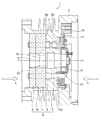
図1および図2に示す電動機1は、三相交流シンクロナスモータを構成し、円筒状のハウジング2と、ハウジング2の内部に固定されたステータ部3および配電部10と、図示しないシャフトを回転させるロータ部9とを備える。
An
ロータ部9は、周方向外側に突出する突部を180度間隔に2箇所形成し、回転軸方向Xの途中で突部を90度ずらした状態にする(突部9a,9b)。ロータ部9を永久磁石で構成してもよいが、電動機1が高温に晒される場合には磁気特性が低下するので、例えば電磁鋼板を突状に打ち抜いて回転軸方向Xの途中で突部を90度ずらした状態にする(突部9a,9b)。
The
このロータ部9にシャフトを固着して、ロータ部9と一体にシャフトを回転させることにより、ロータ部9に発生した回転力を外部出力する。電動機1を自動車用ターボチャージャおよび電動コンプレッサ等に適用する場合、ロータ部9に固着したシャフトをタービン(いわゆるインペラ)の回転軸に連結して、電動機1によりタービンを回転駆動する。
By fixing the shaft to the
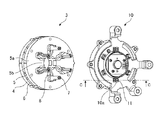
ステータ部3は、2個のステータコア4,5と、このステータコア4,5の間に配置されたマグネット6と、6個のU字状のステータ側コイル7と、これらを一体化するモールド部8とから構成される。ステータコア4,5はそれぞれ、電磁鋼板を回転軸方向Xに積層して構成する。図2に示すように、このステータコア5は、環状体5aと、この環状体5aの内周部から中心に向かって突出する6個の突部(以下、ティース5b)とからなる。なお、図1および図2では隠れて見えないが、ステータコア4も環状体4aと6個のティース4bとからなる。また、マグネット6は環状体4a,5aと略同形状である。
The
ステータ側コイル7は、銅板をU字に折り曲げた1回巻のコイルである。回転軸方向Xに対向する1組のティース4b,5bに対して1個のステータ側コイル7が装着される。モールド部8は、ステータコア4,5、マグネット6およびステータ側コイル7を一体成形する樹脂部材で構成される。各ティース4b,5bに装着されモールドされた各ステータ側コイル7は、モールド部8を回転軸方向Xに貫通して、折り曲げ部分がステータコア4側に、先端部分がステータコア5側に突出している。ステータ部3を一体成形する際に、各ステータ側コイル7の先端部分を金型の内壁に当接させて高さ方向の位置合わせをすることにより、ステータ側コイル7同士の先端部分の高さ方向のずれを抑制している。
The
配電部10は、銅板の配電側コイル11を一体成形する樹脂部材で構成される。この配電側コイル11は、シャフトの周方向に沿って環状に配置されて、一方の端部がステータ側コイル7に接続され、他方の端部が不図示のインバータ基板に接続される。配電部10には、ステータ側コイル7の先端部分を貫通させるための貫通孔10aが形成されており、貫通孔10aを貫通したステータ側コイル7は、貫通孔10aの内部から開口に向かって配設された配電側コイル11と並列に対向する。この貫通孔10aの詳細は後述する。
The
配電側コイル11に接続するインバータ基板は、外部電源を交流電流に変換し、位置検出センサ12から入力される位置信号に基づいて配電側コイル11のU相、V相、W相の三相を順次切り替えて配電側コイル11からステータ側コイル7へ電流を流す。また、配電部10の中央には位置検出センサ12が設置されている。この位置検出センサ12は、シャフトに固定されたターゲットの位置を検出して、シャフトの回転位置を示す位置信号を出力する。
The inverter board connected to the
次に、電動機1の動作概略を説明する。
回転軸方向Xに着磁されたマグネット6による磁束は、マグネット6のN極側に配置されたステータコア4のティース4bからロータ部9の突部9aに流れ出て、ロータ部9を回転軸方向Xに進んでS極側にある突部9bから出て、ロータ部9のS極側に配置されたステータコア5のティース5bへ流れ入る界磁磁束となる。このように、マグネット6の界磁起磁力がロータ部9に作用することで、マグネット6のN極側に対面するロータ部9の突部9aをN極に着磁し、マグネット6のS極側に対面するロータ部9の突部9bをS極に着磁する。
図3は、配電部10側から見たステータ部3とロータ部9の平面図である。ただし、ハウジング2およびステータ側コイル7等は図示を省略する。配電部10の配電側コイル11を経由してU字状のステータ側コイル7に電流が流れると、流れた電流の向きに応じてステータコア4,5の各ティース4b,5bが着磁して回転磁界が生じ、トルクが発生する。ステータ側コイル7に流す電流の向きを順次切り替えることにより、図3(a)〜図3(c)のように各ティース4b,5bのNS各極性が回転移動していき、磁気作用によりロータ部9が回転する。
Next, an outline of the operation of the
The magnetic flux generated by the
FIG. 3 is a plan view of the
次に、電動機1の組み立て手順を説明する。
図1に示すように、ハウジング2にはステータ部3の一端面に当接する当接部2aと、配電部10の一端面に当接する当接部2bが形成されている。一体成形したステータ部3をA方向よりハウジング2に圧入し、当接部2aに当接させる。また、一体成形した配電部10をB方向よりハウジング2に挿入し、当接部2bに当接させてネジ等で組み付ける。このとき、ステータ側コイル7の先端部分を配電部10の貫通孔10aに貫通させて、ステータ側コイル7と配電側コイル11とを並列に配し、TIG溶接を実施して両コイルを電気的に接続する。この電動機1ではステータ側コイル7を6個使用するので、1個につき溶接部13が2箇所、全部で12箇所になる。
Next, the assembly procedure of the
As shown in FIG. 1, the
なお、上記説明では、ステータ側コイル7をモールドしたステータ部3をハウジング2に組み付けているが、この組み立て手順に限定されるものではない。例えば、ステータ部3を一体成形する際、ステータ側コイル7をモールドせず、代わりに、このステータ側コイル7を挿通するための挿通孔(不図示)をモールド部8に形成しておく。そして、ステータ部3をハウジング2に組み付けた後、挿通孔にステータ側コイル7をアウトサートする。
In the above description, the
あるいは、ハウジング2に当接部2a,2b等の段差が無い場合(不図示)には、ステータ部3と配電部10を同一方向から組み付け可能である。その場合、先ずステータ部3を配電部10に固定し、ステータ側コイル7の先端部分を配電部10の貫通孔10aに貫通させ、TIG溶接を実施してステータ側コイル7と配電側コイル11を電気的に接続する。その後、ステータ部3と配電部10を、一方向からハウジング2に挿入して固定する。
Alternatively, when the
次に、ステータ側コイル7と配電側コイル11の溶接方法を説明する。
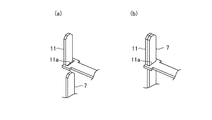
図4は、配電部10の貫通孔10a周辺を、図2のCC線に沿って切断した断面図であり、図4(a)は貫通孔10aにステータ側コイル7を挿入する前の状態、図4(b)は挿入した状態を示す。図5は、配電側コイル11の形状を説明する斜視図であり、図5(a)は開口部11aにステータ側コイル7を挿入する前の状態、図4(b)は挿入した状態を示す。
Next, a method for welding the
4 is a cross-sectional view of the periphery of the through
図5に示すように、配電側コイル11は、L字に折れ曲がった形状であり、折れ曲がり部分にステータ側コイル7を挿通する開口部11aが形成されている。形状加工した配電側コイル11を樹脂部材でモールドして配電部10を成形する際に、図4に示すように、貫通孔10aと開口部11aとを連通させる。よって、配電側コイル11は貫通孔10aを横断してL字に折れ曲がり、折れ曲がり部分が貫通孔10aの内壁面に当接した状態で回転軸方向Xに配設され、貫通孔10aの出口側開口10a−2から突出する。
As shown in FIG. 5, the power
貫通孔10aは、ステータ側コイル7を挿入する入口側開口10a−1の開口面積に比べて、ステータ側コイル7および配電側コイル11を露出させる出口側開口10a−2の開口面積を狭くしている。このとき、ステータ側コイル7に対向する側の内壁面を、入口側開口10a−1から出口側開口10a−2に向かってすぼまるテーパ形状にして、この内壁面でステータ側コイル7を配電側コイル11の方向へ押圧する。
The through
図4(a)に示すように、ステータ側コイル7は、入口側開口10a−1から貫通孔10aに挿入されて配電側コイル11の開口部11aを挿通し、出口側開口10a−2から露出する。そして、図4(b)に示すように、出口側開口10a−2側の内壁面が、押圧力Fで、ステータ側コイル7を配電側コイル11の折れ曲がり部分へ押圧し、ステータ側コイル7と配電側コイル11とが隙間無く密着した状態が維持される。また、押圧力Fが作用することで、開口部11aの縁11bにステータ側コイル7が当接し、この部位が支点となってステータ側コイル7の先端部分が配電側コイル11の方向へ撓み、密着性が向上する。
この状態でステータ側コイル7と配電側コイル11の端部同士をTIG溶接し、溶接部13とする。これにより、溶接部13のTIG溶接性が安定し、片側溶接および溶け込み不良が発生せず、良好に通電可能となる。
As shown in FIG. 4 (a), the
In this state, the end portions of the
以上より、実施の形態1によれば、電動機1は、シャフトに一体化したロータ部9と、ロータ部9の外周を囲う位置に固定され、平板状のステータ側コイル7がシャフトの回転軸方向Xと平行に配設されたステータ部3と、ステータ側コイル7の端部を貫通させる貫通孔10a、および、貫通孔10aに回転軸方向Xと平行に配設されて貫通孔10aの開口から露出し、貫通孔10aを貫通したステータ側コイル7と溶接された平板状の配電側コイル11を有し、この配電側コイル11を介してステータ部3に電力供給する配電部10とを備え、配電側コイル11は、貫通孔10a内を横断して回転軸方向Xへ折れ曲がり、この折れ曲がり部分が貫通孔10aの内壁面に当接した状態に配設されると共に、貫通孔10aを横断した部分に、ステータ側コイル7を挿通する開口部11aが形成され、貫通孔10aは、ステータ側コイル7の入口側開口10a−1に比べて出口側開口10a−2が狭く、開口部11aに挿通されたステータ側コイル7の端部を配電側コイル11の折れ曲がり部分へ押圧接触させる形状になるよう構成した。このため、ステータ側コイル7の入口側開口10a−1より出口側開口10a−2を狭めた形状の貫通孔10aが、ステータ側コイル7を配電側コイル11へ押圧接触させるようにしたので、両コイルが隙間無く密着した状態で溶接できるようになり、溶接性を向上させた電動機1を提供することができる。
As described above, according to the first embodiment, the
なお、本願発明はその発明の範囲内において、各実施の形態の自由な組み合わせ、あるいは各実施の形態の任意の構成要素の変形、もしくは各実施の形態において任意の構成要素の省略が可能である。 In the present invention, within the scope of the invention, any combination of the embodiments, or any modification of any component in each embodiment, or omission of any component in each embodiment is possible. .
1 電動機、2 ハウジング、2a,2b 当接部、3 ステータ部、4,5 ステータコア、4a,5a 環状体、4b,5b ティース、6 マグネット、7 ステータ側コイル、8 モールド部、9 ロータ部、9a,9b 突極、10 配電部、10a 貫通孔、10a−1 入口側開口、10a−2 出口側開口、11 配電側コイル、11a 開口部、11b 縁、12 位置検出センサ、13 溶接部、100 ステータ側コイル、101 配電側コイル、102 溶接機、103 溶接部
DESCRIPTION OF
Claims (1)
前記ロータ部の外周を囲う位置に固定され、平板状のステータ側コイルが前記シャフトの軸方向と平行に配設されたステータ部と、
前記ステータ側コイルの端部を貫通させる貫通孔、および、前記貫通孔に軸方向と平行に配設されて前記貫通孔開口から露出し、前記貫通孔を貫通したステータ側コイルと溶接された平板状の配電側コイルを有し、当該配電側コイルを介して前記ステータ部に電力供給する配電部とを備え、
前記配電側コイルは、前記貫通孔内を横断して前記軸方向へ折れ曲がり、当該折れ曲がり部分が前記貫通孔の内壁面に当接した状態に配設されると共に、前記貫通孔横断部分に、前記ステータ側コイルを挿通する開口部が形成され、
前記貫通孔は、前記ステータ側コイルの入口側の開口面積に比べて出口側の開口面積が狭く、前記開口部に挿通された前記ステータ側コイル端部を前記配電側コイルの前記折れ曲がり部分へ押圧接触させる形状であることを特徴とする電動機。 A rotor unit integrated with the shaft;
A stator portion fixed at a position surrounding the outer periphery of the rotor portion, and a plate-like stator side coil disposed parallel to the axial direction of the shaft;
A through hole that penetrates the end of the stator side coil, and a flat plate that is disposed parallel to the axial direction in the through hole and exposed from the through hole opening and welded to the stator side coil that penetrates the through hole A power distribution side coil, and a power distribution unit that supplies power to the stator unit via the power distribution side coil,
The distribution-side coil is bent in the axial direction across the through-hole, and the bent portion is disposed in contact with the inner wall surface of the through-hole. An opening for inserting the stator side coil is formed,
The through-hole has a smaller opening area on the outlet side than the opening area on the inlet side of the stator-side coil, and presses the end of the stator-side coil inserted through the opening to the bent portion of the distribution-side coil. An electric motor having a shape to be brought into contact with.
Priority Applications (1)
| Application Number | Priority Date | Filing Date | Title |
|---|---|---|---|
| JP2012139576A JP2014007782A (en) | 2012-06-21 | 2012-06-21 | Electric motor |
Applications Claiming Priority (1)
| Application Number | Priority Date | Filing Date | Title |
|---|---|---|---|
| JP2012139576A JP2014007782A (en) | 2012-06-21 | 2012-06-21 | Electric motor |
Publications (1)
| Publication Number | Publication Date |
|---|---|
| JP2014007782A true JP2014007782A (en) | 2014-01-16 |
Family
ID=50105078
Family Applications (1)
| Application Number | Title | Priority Date | Filing Date |
|---|---|---|---|
| JP2012139576A Pending JP2014007782A (en) | 2012-06-21 | 2012-06-21 | Electric motor |
Country Status (1)
| Country | Link |
|---|---|
| JP (1) | JP2014007782A (en) |
-
2012
- 2012-06-21 JP JP2012139576A patent/JP2014007782A/en active Pending
Similar Documents
| Publication | Publication Date | Title |
|---|---|---|
| JP5791800B2 (en) | Electric motor | |
| JP5729091B2 (en) | Bus bar, motor and manufacturing method thereof | |
| JP5842361B2 (en) | Motor and motor manufacturing method | |
| JP2010220288A (en) | Core block and magnetic pole core for motors using the core block | |
| US20070286753A1 (en) | Electric motor | |
| JP6184239B2 (en) | Welded structure and electric motor | |
| CN112368912A (en) | Distributed winding radial gap type rotating electric machine and stator thereof | |
| CN108370178A (en) | Axial-gap rotary electric machine and its manufacturing method | |
| WO2009113215A1 (en) | Stator core for dynamo-electric machine and manufacturing method therefor | |
| JP2001292542A (en) | Method for manufacturing stator core of electric motor and stator | |
| JP2020089119A (en) | Rotating electric machine stator | |
| CN110571965B (en) | Rotating electric machine and method for manufacturing same | |
| CN114651387B (en) | Method for manufacturing stator of rotating electric machine, stator of rotating electric machine, and rotating electric machine | |
| JP7382574B2 (en) | A connection structure between a coil and a bus bar, and a motor having the same | |
| JP2014007781A (en) | Electric motor | |
| JP5924194B2 (en) | Multi-gap rotating electric machine | |
| JP6824032B2 (en) | How to assemble a reluctance rotary electric machine and a reluctance rotary electric machine | |
| JP2005168127A (en) | Permanent magnet rotor | |
| JP5518253B2 (en) | Electric motor | |
| JP2014007782A (en) | Electric motor | |
| JP2005086985A (en) | Stator and brushless motor using stator | |
| JP5269270B2 (en) | Electric motor and method of manufacturing electric motor | |
| JP5937458B2 (en) | Stator, outer rotor type rotating electrical machine using the stator, and stator manufacturing method | |
| JP2015149852A (en) | Rotating electric machine | |
| JP2007252030A (en) | Insulator and motor |