JP2014007789A - Electric linear actuator - Google Patents
Electric linear actuator Download PDFInfo
- Publication number
- JP2014007789A JP2014007789A JP2012139827A JP2012139827A JP2014007789A JP 2014007789 A JP2014007789 A JP 2014007789A JP 2012139827 A JP2012139827 A JP 2012139827A JP 2012139827 A JP2012139827 A JP 2012139827A JP 2014007789 A JP2014007789 A JP 2014007789A
- Authority
- JP
- Japan
- Prior art keywords
- housing
- gap portion
- gap
- linear actuator
- curable material
- Prior art date
- Legal status (The legal status is an assumption and is not a legal conclusion. Google has not performed a legal analysis and makes no representation as to the accuracy of the status listed.)
- Granted
Links
Images


Classifications
-
- F—MECHANICAL ENGINEERING; LIGHTING; HEATING; WEAPONS; BLASTING
- F16—ENGINEERING ELEMENTS AND UNITS; GENERAL MEASURES FOR PRODUCING AND MAINTAINING EFFECTIVE FUNCTIONING OF MACHINES OR INSTALLATIONS; THERMAL INSULATION IN GENERAL
- F16H—GEARING
- F16H25/00—Gearings comprising primarily only cams, cam-followers and screw-and-nut mechanisms
- F16H25/18—Gearings comprising primarily only cams, cam-followers and screw-and-nut mechanisms for conveying or interconverting oscillating or reciprocating motions
- F16H25/20—Screw mechanisms
- F16H25/22—Screw mechanisms with balls, rollers, or similar members between the co-operating parts; Elements essential to the use of such members
- F16H25/2204—Screw mechanisms with balls, rollers, or similar members between the co-operating parts; Elements essential to the use of such members with balls
-
- F—MECHANICAL ENGINEERING; LIGHTING; HEATING; WEAPONS; BLASTING
- F16—ENGINEERING ELEMENTS AND UNITS; GENERAL MEASURES FOR PRODUCING AND MAINTAINING EFFECTIVE FUNCTIONING OF MACHINES OR INSTALLATIONS; THERMAL INSULATION IN GENERAL
- F16H—GEARING
- F16H57/00—General details of gearing
- F16H57/02—Gearboxes; Mounting gearing therein
- F16H57/029—Gearboxes; Mounting gearing therein characterised by means for sealing the gearboxes, e.g. to improve airtightness
-
- H—ELECTRICITY
- H02—GENERATION; CONVERSION OR DISTRIBUTION OF ELECTRIC POWER
- H02K—DYNAMO-ELECTRIC MACHINES
- H02K7/00—Arrangements for handling mechanical energy structurally associated with dynamo-electric machines, e.g. structural association with mechanical driving motors or auxiliary dynamo-electric machines
- H02K7/06—Means for converting reciprocating motion into rotary motion or vice versa
-
- C—CHEMISTRY; METALLURGY
- C09—DYES; PAINTS; POLISHES; NATURAL RESINS; ADHESIVES; COMPOSITIONS NOT OTHERWISE PROVIDED FOR; APPLICATIONS OF MATERIALS NOT OTHERWISE PROVIDED FOR
- C09K—MATERIALS FOR MISCELLANEOUS APPLICATIONS, NOT PROVIDED FOR ELSEWHERE
- C09K3/00—Materials not provided for elsewhere
- C09K3/10—Materials in mouldable or extrudable form for sealing or packing joints or covers
- C09K2003/1034—Materials or components characterised by specific properties
- C09K2003/1059—Heat-curable materials
-
- C—CHEMISTRY; METALLURGY
- C09—DYES; PAINTS; POLISHES; NATURAL RESINS; ADHESIVES; COMPOSITIONS NOT OTHERWISE PROVIDED FOR; APPLICATIONS OF MATERIALS NOT OTHERWISE PROVIDED FOR
- C09K—MATERIALS FOR MISCELLANEOUS APPLICATIONS, NOT PROVIDED FOR ELSEWHERE
- C09K2200/00—Chemical nature of materials in mouldable or extrudable form for sealing or packing joints or covers
- C09K2200/06—Macromolecular organic compounds, e.g. prepolymers
- C09K2200/068—Containing also other elements than carbon, oxygen or nitrogen in the polymer main chain
- C09K2200/0685—Containing silicon
-
- F—MECHANICAL ENGINEERING; LIGHTING; HEATING; WEAPONS; BLASTING
- F16—ENGINEERING ELEMENTS AND UNITS; GENERAL MEASURES FOR PRODUCING AND MAINTAINING EFFECTIVE FUNCTIONING OF MACHINES OR INSTALLATIONS; THERMAL INSULATION IN GENERAL
- F16H—GEARING
- F16H15/00—Gearings for conveying rotary motion with variable gear ratio, or for reversing rotary motion, by friction between rotary members
- F16H15/02—Gearings for conveying rotary motion with variable gear ratio, or for reversing rotary motion, by friction between rotary members without members having orbital motion
- F16H15/04—Gearings providing a continuous range of gear ratios
- F16H15/06—Gearings providing a continuous range of gear ratios in which a member A of uniform effective diameter mounted on a shaft may co-operate with different parts of a member B
- F16H15/08—Gearings providing a continuous range of gear ratios in which a member A of uniform effective diameter mounted on a shaft may co-operate with different parts of a member B in which the member B is a disc with a flat or approximately flat friction surface
- F16H15/14—Gearings providing a continuous range of gear ratios in which a member A of uniform effective diameter mounted on a shaft may co-operate with different parts of a member B in which the member B is a disc with a flat or approximately flat friction surface in which the axes of the members are parallel or approximately parallel
-
- F—MECHANICAL ENGINEERING; LIGHTING; HEATING; WEAPONS; BLASTING
- F16—ENGINEERING ELEMENTS AND UNITS; GENERAL MEASURES FOR PRODUCING AND MAINTAINING EFFECTIVE FUNCTIONING OF MACHINES OR INSTALLATIONS; THERMAL INSULATION IN GENERAL
- F16H—GEARING
- F16H15/00—Gearings for conveying rotary motion with variable gear ratio, or for reversing rotary motion, by friction between rotary members
- F16H15/02—Gearings for conveying rotary motion with variable gear ratio, or for reversing rotary motion, by friction between rotary members without members having orbital motion
- F16H15/04—Gearings providing a continuous range of gear ratios
- F16H15/40—Gearings providing a continuous range of gear ratios in which two members co-operative by means of balls, or rollers of uniform effective diameter, not mounted on shafts
-
- F—MECHANICAL ENGINEERING; LIGHTING; HEATING; WEAPONS; BLASTING
- F16—ENGINEERING ELEMENTS AND UNITS; GENERAL MEASURES FOR PRODUCING AND MAINTAINING EFFECTIVE FUNCTIONING OF MACHINES OR INSTALLATIONS; THERMAL INSULATION IN GENERAL
- F16H—GEARING
- F16H25/00—Gearings comprising primarily only cams, cam-followers and screw-and-nut mechanisms
- F16H25/18—Gearings comprising primarily only cams, cam-followers and screw-and-nut mechanisms for conveying or interconverting oscillating or reciprocating motions
- F16H25/20—Screw mechanisms
- F16H2025/2031—Actuator casings
-
- F—MECHANICAL ENGINEERING; LIGHTING; HEATING; WEAPONS; BLASTING
- F16—ENGINEERING ELEMENTS AND UNITS; GENERAL MEASURES FOR PRODUCING AND MAINTAINING EFFECTIVE FUNCTIONING OF MACHINES OR INSTALLATIONS; THERMAL INSULATION IN GENERAL
- F16H—GEARING
- F16H25/00—Gearings comprising primarily only cams, cam-followers and screw-and-nut mechanisms
- F16H25/18—Gearings comprising primarily only cams, cam-followers and screw-and-nut mechanisms for conveying or interconverting oscillating or reciprocating motions
- F16H25/20—Screw mechanisms
- F16H2025/2062—Arrangements for driving the actuator
- F16H2025/2081—Parallel arrangement of drive motor to screw axis
-
- Y—GENERAL TAGGING OF NEW TECHNOLOGICAL DEVELOPMENTS; GENERAL TAGGING OF CROSS-SECTIONAL TECHNOLOGIES SPANNING OVER SEVERAL SECTIONS OF THE IPC; TECHNICAL SUBJECTS COVERED BY FORMER USPC CROSS-REFERENCE ART COLLECTIONS [XRACs] AND DIGESTS
- Y10—TECHNICAL SUBJECTS COVERED BY FORMER USPC
- Y10T—TECHNICAL SUBJECTS COVERED BY FORMER US CLASSIFICATION
- Y10T74/00—Machine element or mechanism
- Y10T74/18—Mechanical movements
- Y10T74/18568—Reciprocating or oscillating to or from alternating rotary
- Y10T74/18576—Reciprocating or oscillating to or from alternating rotary including screw and nut
Landscapes
- Engineering & Computer Science (AREA)
- General Engineering & Computer Science (AREA)
- Mechanical Engineering (AREA)
- Power Engineering (AREA)
- Transmission Devices (AREA)
- Gear Transmission (AREA)
- Connection Of Motors, Electrical Generators, Mechanical Devices, And The Like (AREA)
Abstract
【課題】簡便かつ省スペースで、はみ出した硬化性材料の脱落を防止し、ハウジングの接合面の強固な密封を図った電動リニアアクチュエータを提供する。
【解決手段】ハウジング2に対して回転不可に、かつ軸方向移動可能に支持されたねじ軸10とで構成された電動リニアアクチュエータ1において、ハウジング2が、第1のハウジング2aと、その端面に衝合された第2のハウジング2bとからなり、これら第1のハウジング2aと第2のハウジング2bの接合面35、36に、断面略半円形に形成された第1の空隙部37と、これに連通し、断面略三角形に形成された第2の空隙部38が対向配置され、第1の空隙部37にシリコーン系液体ガスケットからなる硬化性材料39が充填されると共に、この硬化性材料39が、第1の空隙部37の体積よりも多く、第1の空隙部37と第2の空隙部38の体積よりも少なく設定されている。
【選択図】図5An electric linear actuator is provided that is simple and space-saving, prevents the protruding curable material from falling off, and firmly seals a joint surface of a housing.
In an electric linear actuator (1) composed of a screw shaft (10) supported so as to be non-rotatable and axially movable with respect to a housing (2), the housing (2) has a first housing (2a) and an end surface thereof. A first gap portion 37 formed in a substantially semicircular cross section on the joint surfaces 35 and 36 of the first housing 2a and the second housing 2b. The second gap portion 38 having a substantially triangular cross section is disposed opposite to the first gap portion 37, and the first gap portion 37 is filled with a curable material 39 made of a silicone-based liquid gasket. However, it is set to be larger than the volume of the first gap portion 37 and smaller than the volumes of the first gap portion 37 and the second gap portion 38.
[Selection] Figure 5
Description
本発明は、一般産業用の電動機、自動車等の駆動部に使用されるボールねじ機構を備えた電動リニアアクチュエータ、詳しくは、自動車のトランスミッションやパーキングブレーキ等で、電動モータからの回転入力を、ボールねじ機構を介して駆動軸の直線運動に変換する電動リニアアクチュエータに関するものである。 The present invention relates to an electric linear actuator having a ball screw mechanism used in a drive unit of a general industrial electric motor or automobile, and more specifically, a rotational input from an electric motor is applied to a ball in a transmission or a parking brake of the automobile. The present invention relates to an electric linear actuator that converts a linear motion of a drive shaft through a screw mechanism.
各種駆動部に使用される電動リニアアクチュエータにおいて、電動モータの回転運動を軸方向の直線運動に変換する機構として、台形ねじあるいはラックアンドピニオン等の歯車機構が一般的に使用されている。これらの変換機構は、滑り接触部を伴うため動力損失が大きく、電動モータの大型化や消費電力の増大を余儀なくされている。そのため、より効率的なアクチュエータとしてボールねじ機構が採用されるようになってきた。 In electric linear actuators used for various drive units, a gear mechanism such as a trapezoidal screw or a rack and pinion is generally used as a mechanism for converting the rotational movement of the electric motor into a linear linear movement. Since these conversion mechanisms involve a sliding contact portion, the power loss is large, and it is necessary to increase the size of the electric motor and increase the power consumption. Therefore, a ball screw mechanism has been adopted as a more efficient actuator.
従来の電動アクチュエータとしては、例えば、図6に示すようなものが知られている。この電動アクチュエータ50は、電動モータ51と、この電動モータ51の回転を減速して出力軸52に伝達する減速機構53と、減速機構53を収納し、出力軸52の一端側に開口部54を有するギヤケーシング55と、ギヤケーシング55の開口部54を閉塞するエンドカバー56とを備え、ギヤケーシング55とエンドカバー56との間に、少なくとも出力軸52の一端を軸支可能な中間カバー57を設け、この中間カバー57よりもギヤケーシング55側に減速機構53を収納すると共に、中間カバー57よりもエンドカバー56側に出力軸52の回転位置を検出する回転位置検出装置58を配設している。
As a conventional electric actuator, for example, one shown in FIG. 6 is known. The
ギヤケーシング55の開口部54には、これを閉塞するエンドカバー56がボルト59によって締結されるが、図7に拡大して示すように、ギヤケーシング55の開口部54の周縁には、全周に亘って溝部60が形成され、この溝部60にパッキン61が配設されている。このパッキン61は、ギヤケーシング55とエンドカバー56との合わせ面から内部への塵埃の侵入を防止するためのシールとして機能している(例えば、特許文献1参照。)。
An
然しながら、こうした従来のシール構造では、ギヤケーシング55やエンドカバー56にアルミ合金等の剛性の低い部材を用いると、ギヤケーシング55やエンドカバー56自体が変形し易いことから、パッキン61の弾性変形だけでは変形に伴う隙間を埋めることができず、気密性を確保することが難しい。
However, in such a conventional seal structure, when a low rigidity member such as an aluminum alloy is used for the
本発明は、こうした従来技術の問題点に鑑みてなされたものであり、粘着力のある液体ガスケットを用いて気密性を確保することに着眼し、簡便かつ省スペースで、はみ出した硬化性材料の脱落を防止し、ハウジングの接合面の強固な密封を図った電動リニアアクチュエータを提供することを目的とする。 The present invention has been made in view of such problems of the prior art, focusing on ensuring airtightness using an adhesive liquid gasket, and is a simple, space-saving, protruding curable material. An object of the present invention is to provide an electric linear actuator that prevents dropping and that firmly seals a joint surface of a housing.
係る目的を達成すべく、本発明のうち請求項1に記載の発明は、ハウジングと、このハウジングに取り付けられた電動モータと、この電動モータの回転力をモータ軸を介して伝達する減速機構と、この減速機構を介して前記電動モータの回転運動を駆動軸の軸方向の直線運動に変換するボールねじ機構とを備え、このボールねじ機構が、前記ハウジングに装着された支持軸受を介して回転可能に、かつ軸方向移動不可に支持され、内周に螺旋状のねじ溝が形成されたナットと、このナットに多数のボールを介して内挿され、前記駆動軸と同軸状に一体化され、外周に前記ナットのねじ溝に対応する螺旋状のねじ溝が形成され、前記ハウジングに対して回転不可に、かつ軸方向移動可能に支持されたねじ軸とで構成された電動リニアアクチュエータにおいて、前記ハウジングが、第1のハウジングと、その端面に衝合された第2のハウジングとからなり、これら第1のハウジングと第2のハウジングの接合面が液体の硬化性材料を硬化させることにより密封されている。 In order to achieve such an object, the invention according to claim 1 of the present invention includes a housing, an electric motor attached to the housing, and a speed reduction mechanism that transmits the rotational force of the electric motor via a motor shaft. A ball screw mechanism that converts the rotational motion of the electric motor into a linear motion in the axial direction of the drive shaft via the speed reduction mechanism, and the ball screw mechanism rotates via a support bearing mounted on the housing. A nut that is supported so as not to move in the axial direction and has a spiral thread groove formed on the inner periphery, and is inserted into the nut via a number of balls and is coaxially integrated with the drive shaft. And an electric linear actuator having a screw shaft that is formed on the outer periphery of the screw shaft so as to correspond to the screw groove of the nut and is supported so as to be non-rotatable and axially movable with respect to the housing. The housing includes a first housing and a second housing abutted on an end surface of the first housing, and a joint surface between the first housing and the second housing cures the liquid curable material. It is sealed by.
このように、モータの回転力を伝達する減速機構と、この減速機構を介して電動モータの回転運動を駆動軸の軸方向の直線運動に変換するボールねじ機構とを備え、ボールねじ機構が、ハウジングに装着された一対の支持軸受を介して回転可能に、かつ軸方向移動不可に支持され、内周に螺旋状のねじ溝が形成されたナットと、このナットに多数のボールを介して内挿され、駆動軸と同軸状に一体化され、外周にナットのねじ溝に対応する螺旋状のねじ溝が形成され、ハウジングに対して回転不可に、かつ軸方向移動可能に支持されたねじ軸とで構成された電動リニアアクチュエータにおいて、ハウジングが、第1のハウジングと、その端面に衝合された第2のハウジングとからなり、これら第1のハウジングと第2のハウジングの接合面が液体の硬化性材料を硬化させることにより密封されているので、ハウジングが大きな変形を受けても硬化性材料の粘着力により硬化性材料が変形に追従して、確実にハウジング同士を密着させることができ、気密性を確保して、ハウジングの接合面の強固な密封を図った電動リニアアクチュエータを提供することができる。 Thus, a reduction mechanism that transmits the rotational force of the motor, and a ball screw mechanism that converts the rotational movement of the electric motor into a linear movement in the axial direction of the drive shaft via the reduction mechanism, A nut that is rotatably supported through a pair of support bearings mounted on the housing and is not axially movable, and has a spiral thread groove formed on the inner periphery, and a plurality of balls are provided in the nut. Screw shaft that is inserted and coaxially integrated with the drive shaft, and has a helical thread groove corresponding to the thread groove of the nut on the outer periphery, and is supported so that it cannot rotate with respect to the housing and can move in the axial direction In the electric linear actuator constituted by the above, the housing is composed of a first housing and a second housing abutted on the end face, and a joining surface between the first housing and the second housing is Since it is sealed by curing the curable material of the body, even if the housing is subjected to a large deformation, the curable material can follow the deformation by the adhesive force of the curable material, and the housings can be securely adhered to each other In addition, it is possible to provide an electric linear actuator that ensures airtightness and that firmly seals the joint surface of the housing.
好ましくは、請求項2に記載の発明のように、前記硬化性材料がシリコーン系液体ガスケットであれば、一定の時間が経過すれば硬化するため、概ね24時間で密封性を発揮することができる。 Preferably, if the curable material is a silicone-based liquid gasket as in the second aspect of the invention, it cures after a certain period of time, and thus can exhibit sealing performance in approximately 24 hours. .
また、請求項3に記載の発明のように、前記1のハウジングと第2のハウジングの接合面に、第1の空隙部と、この第1の空隙部に連通する第2の空隙部が対向して形成され、前記第1の空隙部に前記硬化性材料が充填されると共に、充填される硬化性材料が、前記第1の空隙部の体積よりも多く、かつ、前記第1の空隙部と第2の空隙部の体積よりも少なく設定されていれば、第1の空隙部からはみ出した硬化性材料の余剰分が、対向する第2の空隙部に充填されることになり、第2の空隙部から硬化性材料が外部にまではみ出すのを防止することができ、はみ出した余剰分の硬化性材料が脱落したり、外観を損なうと言った不具合を防止することができるので、ハウジングの接合面の強固な密封を図ることができる。 Further, as in the invention described in claim 3, the first gap portion and the second gap portion communicating with the first gap portion are opposed to the joint surface between the first housing and the second housing. The first gap is filled with the curable material, and the curable material to be filled is larger than the volume of the first gap, and the first gap If the volume is set to be smaller than the volume of the second gap portion, the surplus portion of the curable material that protrudes from the first gap portion is filled in the opposing second gap portion. It is possible to prevent the curable material from protruding to the outside from the void portion of the housing, and it is possible to prevent the trouble that the excess curable material that has protruded falls off or impairs the appearance. A strong sealing of the joint surface can be achieved.
また、請求項4に記載の発明のように、前記第1の空隙部が断面略半円形に形成されると共に、前記第2の空隙部が断面略三角形に形成されていれば、簡便かつ省スペースで、はみ出した硬化性材料の脱落を効果的に防止することができる。 Further, as in the invention described in claim 4, it is simple and saving if the first gap is formed in a substantially semicircular cross section and the second gap is formed in a substantially triangular cross section. The space can effectively prevent the protruding curable material from falling off.
本発明に係る電動リニアアクチュエータは、ハウジングと、このハウジングに取り付けられた電動モータと、この電動モータの回転力をモータ軸を介して伝達する減速機構と、この減速機構を介して前記電動モータの回転運動を駆動軸の軸方向の直線運動に変換するボールねじ機構とを備え、このボールねじ機構が、前記ハウジングに装着された支持軸受を介して回転可能に、かつ軸方向移動不可に支持され、内周に螺旋状のねじ溝が形成されたナットと、このナットに多数のボールを介して内挿され、前記駆動軸と同軸状に一体化され、外周に前記ナットのねじ溝に対応する螺旋状のねじ溝が形成され、前記ハウジングに対して回転不可に、かつ軸方向移動可能に支持されたねじ軸とで構成された電動リニアアクチュエータにおいて、前記ハウジングが、第1のハウジングと、その端面に衝合された第2のハウジングとからなり、これら第1のハウジングと第2のハウジングの接合面が液体の硬化性材料を硬化させることにより密封されているので、ハウジングが大きな変形を受けても硬化性材料の粘着力により硬化性材料が変形に追従して、確実にハウジング同士を密着させることができ、気密性を確保して、ハウジングの接合面の強固な密封を図った電動リニアアクチュエータを提供することができる。 An electric linear actuator according to the present invention includes a housing, an electric motor attached to the housing, a reduction mechanism that transmits the rotational force of the electric motor through a motor shaft, and the electric motor through the reduction mechanism. A ball screw mechanism that converts rotational motion into linear motion in the axial direction of the drive shaft, and this ball screw mechanism is supported by a support bearing mounted on the housing so as to be rotatable and not movable in the axial direction. , A nut having a helical thread groove formed on the inner periphery, and a nut inserted into the nut via a number of balls, integrated coaxially with the drive shaft, and corresponding to the thread groove of the nut on the outer periphery In the electric linear actuator comprising a screw shaft formed with a spiral screw groove and supported so as not to rotate with respect to the housing and to be movable in the axial direction, The bossing is composed of a first housing and a second housing abutted on the end face, and the joint surface between the first housing and the second housing is sealed by curing the liquid curable material. Therefore, even if the housing is subjected to a large deformation, the curable material can follow the deformation by the adhesive force of the curable material, and the housings can be securely adhered to each other, ensuring airtightness and joining the housing. It is possible to provide an electric linear actuator that has a strong sealing surface.
アルミ合金製のハウジングと、このハウジングに取り付けられた電動モータと、この電動モータの回転力をモータ軸を介して伝達する減速機構と、この減速機構を介して前記電動モータの回転運動を駆動軸の軸方向の直線運動に変換するボールねじ機構とを備え、このボールねじ機構が、前記ハウジングに装着された支持軸受を介して回転可能に、かつ軸方向移動不可に支持され、内周に螺旋状のねじ溝が形成されたナットと、このナットに多数のボールを介して内挿され、前記駆動軸と同軸状に一体化され、外周に前記ナットのねじ溝に対応する螺旋状のねじ溝が形成され、前記ハウジングに対して回転不可に、かつ軸方向移動可能に支持されたねじ軸とで構成された電動リニアアクチュエータにおいて、前記ハウジングが、第1のハウジングと、その端面に衝合された第2のハウジングとからなり、これら第1のハウジングと第2のハウジングの接合面に、断面略半円形に形成された第1の空隙部と、この第1の空隙部に連通し、断面略三角形に形成された第2の空隙部が対向配置され、前記第1の空隙部にシリコーン系液体ガスケットからなる硬化性材料が充填されると共に、この硬化性材料が、前記第1の空隙部の体積よりも多く、かつ、前記第1の空隙部と第2の空隙部の体積よりも少なく設定されている。 A housing made of aluminum alloy, an electric motor attached to the housing, a reduction mechanism that transmits the rotational force of the electric motor via a motor shaft, and a rotational axis of the electric motor via the reduction mechanism A ball screw mechanism that converts the linear screw motion into an axial linear motion of the motor, and the ball screw mechanism is supported by a support bearing mounted on the housing so as to be rotatable and non-movable in the axial direction. And a helical thread groove that is inserted into the nut through a large number of balls, is coaxially integrated with the drive shaft, and corresponds to the thread groove of the nut on the outer periphery. And a screw shaft that is supported so as to be non-rotatable and axially movable with respect to the housing, wherein the housing includes a first housing. And a second housing abutted on the end surface thereof, and a first gap portion formed in a substantially semicircular cross section on the joint surface between the first housing and the second housing, and the first housing A second void portion having a substantially triangular cross section is disposed opposite to the first void portion, and the first void portion is filled with a curable material made of a silicone-based liquid gasket. The material is set to be larger than the volume of the first gap and less than the volumes of the first gap and the second gap.
以下、本発明の実施の形態を図面に基づいて詳細に説明する。
図1は、本発明に係る電動リニアアクチュエータの一実施形態を示す縦断面図、図2は、図1のアクチュエータ本体を示す縦断面図、図3は、図1の中間歯車部を示す縦断面図、図4は、図3の変形例を示す要部拡大図、図5は、図1のハウジングの接合部を示す要部拡大図である。
Hereinafter, embodiments of the present invention will be described in detail with reference to the drawings.
1 is a longitudinal sectional view showing an embodiment of an electric linear actuator according to the present invention, FIG. 2 is a longitudinal sectional view showing an actuator body of FIG. 1, and FIG. 3 is a longitudinal sectional view showing an intermediate gear portion of FIG. 4 is an enlarged view of a main part showing a modification of FIG. 3, and FIG. 5 is an enlarged view of the main part showing a joint part of the housing in FIG.
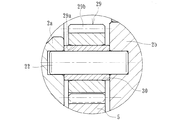
この電動リニアアクチュエータ1は、図1に示すように、円筒状のハウジング2と、このハウジング2に取り付けられた電動モータ(図示せず)と、この電動モータのモータ軸3aに取付けられた入力歯車3に噛合する中間歯車4と、この中間歯車4に噛合する出力歯車5とからなる減速機構6と、この減速機構6を介して電動モータの回転運動を駆動軸7の軸方向の直線運動に変換するボールねじ機構8と、このボールねじ機構8を備えたアクチュエータ本体9とを備えている。
As shown in FIG. 1, the electric linear actuator 1 includes a
ハウジング2はA6063TEやADC12等のアルミ合金からアルミダイカストによって形成され、第1のハウジング2aと、その端面に衝合された第2のハウジング2bとからなり、固定ボルト(図示せず)によって一体に固定されている。第1のハウジング2aには電動モータが取り付けられると共に、これら第1のハウジング2aと第2のハウジング2bの衝合部には、ねじ軸10を収容するための袋孔11、12が形成されている。
The
電動モータのモータ軸3aは、その端部に入力歯車3が圧入により相対回転不能に取り付けられ、第2のハウジング2bに装着された深溝玉軸受からなる転がり軸受13によって回転自在に支持されている。平歯車からなる中間歯車4に噛合する出力歯車5は、後述するボールねじ機構8を構成するナット18にキー14を介して一体に固定されている。
The
駆動軸7は、ボールねじ機構8を構成するねじ軸10と一体に構成され、この駆動軸7の一端部(図中右端部)に係止ピン15、15が植設され、第2のハウジング2bに装着された止め輪16に当接することにより抜け出しを防止し、ねじ軸10がハウジング2の内壁に衝突して作動ロックの状態となるのを確実に回避することができる。ここで、17は、ハウジング2bの袋孔12に装着されたスリーブで、軸方向に形成された凹溝17a、17aに係止ピン15、15を係合させることにより、ねじ軸10が、回転不可に、かつ軸方向移動可能に支持されている。
The
ボールねじ機構8は、図2に拡大して示すように、ねじ軸10と、このねじ軸10にボール19を介して外挿されたナット18とを備えている。ねじ軸10は、外周に螺旋状のねじ溝10aが形成されている。一方、ナット18は、ねじ軸10に外挿されると共に、内周にねじ軸10のねじ溝10aに対応する螺旋状のねじ溝18aが形成され、これらねじ溝10a、18aとの間に多数のボール19が転動自在に収容されている。そして、ナット18は、ハウジング2a、2bに対して、2つの支持軸受20、20を介して回転自在に、かつ軸方向移動不可に支承されている。21は、ナット18のねじ溝18aを連結して循環部材を構成する駒部材で、この駒部材21によって多数のボール19が無限循環することができる。
As shown in an enlarged view in FIG. 2, the
各ねじ溝10a、18aの断面形状は、サーキュラアーク形状であってもゴシックアーク形状であっても良いが、ここではボール19との接触角が大きくとれ、アキシアルすきまが小さく設定できるゴシックアーク形状に形成されている。これにより、軸方向荷重に対する剛性が高くなり、かつ振動の発生を抑制することができる。
The cross-sectional shape of each of the
ナット18はSCM415やSCM420等の肌焼き鋼からなり、真空浸炭焼入れによってその表面に55〜62HRCの範囲に硬化処理が施されている。これにより、熱処理後のスケール除去のためのバフ加工等を省略することができ、低コスト化を図ることができる。一方、ねじ軸10はS55C等の中炭素鋼あるいはSCM415やSCM420等の肌焼き鋼からなり、高周波焼入れ、あるいは浸炭焼入れによってその表面に55〜62HRCの範囲に硬化処理が施されている。
The
ナット18の外周面18bには減速機構6を構成する出力歯車5が一体に固定されると共に、この出力歯車5の両側に2つの支持軸受20、20が所定のシメシロを介して圧入されている。これにより、駆動軸7からスラスト荷重が負荷されても支持軸受20、20と出力歯車5の軸方向の位置ズレを防止することができる。また、2つの支持軸受20、20は、両端部にシールド板20a、20aが装着された密封型の深溝玉軸受で構成され、軸受内部に封入された潤滑グリースの外部への漏洩と、外部から摩耗粉等が軸受内部に侵入するのを防止している。
The
また、本実施形態では、ナット18を回転自在に支持する支持軸受20が同じ仕様の深溝玉軸受で構成されているので、前述した駆動軸7からスラスト荷重および出力歯車5を介して負荷されるラジアル荷重の両方を負荷することができると共に、組立時に誤組み防止のための確認作業を簡便化することができ、組立作業性を向上させることができる。なお、同一仕様の転がり軸受とは、軸受の内径、外径、幅寸法をはじめ、転動体サイズ、個数および軸受内部すきま等が同一なものを言う。
Further, in the present embodiment, the support bearing 20 that rotatably supports the
また、ここでは、一対の支持軸受20、20のうち一方の支持軸受20がリング状の弾性部材からなるワッシャ27を介して第1のハウジング2aに装着されている。このワッシャ27は、強度や耐摩耗性が高いオーステナイト系ステンレス鋼板(JIS規格のSUS304系等)、あるいは防錆処理された冷間圧延鋼板(JIS規格のSPCC系等)からプレス加工にて形成されたウェーブワッシャからなる。そして、その内径Dが支持軸受20の内輪外径dよりも大径に形成されている。これにより、一対の支持軸受20、20の軸方向ガタをなくすことができ、円滑な回転性能を得ることができると共に、ワッシャ27が、支持軸受20の外輪のみに当接し、回転輪となる内輪とは干渉しないため、逆スラスト荷重が生じてナット18が第1のハウジング2a側に押し付けられても支持軸受20の内輪がハウジング2aに当接して摩擦力が上昇するのを防止し、ロック状態になるのを確実に防止することができる。
Also, here, one of the pair of
ここで、図3に示すように、歯車軸22は第1、第2のハウジング2a、2bに植設され、中間歯車4は、転がり軸受23を介してこの歯車軸22に回転自在に支承されている。歯車軸22の端部のうち、例えば、第1のハウジング2a側の端部を圧入する場合、第2のハウジング2b側の端部をすきま嵌めに設定することにより、ミスアライメント(組立誤差)を許容して円滑な回転性能を確保することができる。本実施形態では、転がり軸受23は、中間歯車4の内径4aに圧入される鋼板プレス製の外輪24と、保持器25を介して外輪24に転動自在に収容された複数の針状ころ26とを備えた、所謂シェル型の針状ころ軸受で構成されている。これにより、入手性が高く、低コスト化を図ることができる。
Here, as shown in FIG. 3, the
また、中間歯車4の両側にはリング状のワッシャ28、28が装着され、中間歯車4が直接第1、第2のハウジング2a、2bに接触するのを防止している。ここで、中間歯車4の歯部4bの幅が歯幅よりも小さく形成されている。これにより、ワッシャ28との接触面積を小さくすることができ、回転時の摩擦抵抗を抑えて円滑な回転性能を得ることができる。ここで、ワッシャ28は、強度や耐摩耗性が高いオーステナイト系ステンレス鋼板、あるいは防錆処理された冷間圧延鋼板からプレス加工にて形成された平ワッシャからなる。なお、これ以外にも、例えば、黄銅や焼結金属、または、GF(グラス繊維)等の繊維状強化材が所定量充填されたPA(ポリアミド)66等の熱可塑性の合成樹脂で形成されていても良い。
Moreover, ring-shaped
さらに、転がり軸受23の幅が中間歯車4の歯幅よりも小さく設定されている。これにより、摩擦による軸受側面の摩耗や変形を防止することができ、円滑な回転性能を得ることができる。
Furthermore, the width of the rolling
図4に、図3の変形例を示す。歯車軸22は第1、第2のハウジング2a、2bに植設され、中間歯車29は、滑り軸受30を介してこの歯車軸22に回転自在に支承されている。本実施形態では、中間歯車29は、歯部29bの幅が歯幅と同一に形成されると共に、滑り軸受30は、中間歯車29の内径29aに圧入され、グラファイト微粉末を添加した多孔質金属からなる含油軸受(NTN商品名;ベアファイト)で構成されている。そして、中間歯車29の歯幅よりも大きく設定されている。これにより、ワッシャを装着しなくても中間歯車29が第1、第2のハウジング2a、2bに接触して摩耗するのを防止し、回転時の摩擦抵抗を抑えて円滑な回転性能を得ることができると共に、部品点数増加を抑えて低コスト化を図ることができる。なお、滑り軸受30は、これ以外にも、例えば、射出成形を可能にした熱可塑性ポリイミド樹脂で形成されていても良い。
FIG. 4 shows a modification of FIG. The
スリーブ17はS55C等の中炭素鋼あるいはSCM415やSCM420等の肌焼き鋼から冷間圧造法によって円筒状に形成され、内周には対向する位置に軸方向に延びる凹溝17a、17aが形成されている。そして、この凹溝17aの表面に無電解ニッケルメッキ等の金属メッキが施されている。一方、凹溝17aに係合する係止ピン15の表面にも硬質クロムメッキ等の金属メッキが施されている。これにより、耐摩耗性が向上し、長期間に亘って摩耗を抑制することができる。なお、金属メッキとして、これ以外にも、例えば、亜鉛メッキ、ユニクロメッキ、クロメートメッキ、ニッケルメッキ、クロムメッキ、カニゼンメッキ等を例示することができる。ここで、凹溝17aと係止ピン15は、摺動時に互いが固着するのを防止することができるように、金属メッキは異種材の方が好ましい。
The sleeve 17 is formed in a cylindrical shape by cold forging from medium carbon steel such as S55C or case-hardened steel such as SCM415 or SCM420, and
ここで、図5に示すように、第1のハウジング2aと第2のハウジング2bの接合面35、36において、それぞれ第1の空隙部37と第2の空隙部38が対向して形成されている。そして、第1の空隙部37に硬化性材料39が充填されている。充填される硬化性材料39は、第1の空隙部37の体積よりも多く、また、第1の空隙部37と第2の空隙部38の体積よりも少なく設定されている。すなわち、第1の空隙部37からはみ出した硬化性材料39の余剰分が、対向する第2の空隙部38に充填されることになる。これにより、第2の空隙部38から硬化性材料39が外部にまではみ出すのを防止することができ、はみ出した余剰分の硬化性材料39が脱落したり、外観を損なうと言った不具合を防止することができるので、ハウジングの接合面が液体の硬化性材料を硬化させることにより密封され、ハウジングが大きな変形を受けても硬化性材料の粘着力により硬化性材料が変形に追従して、確実にハウジング同士を密着させることができ、気密性を確保して、ハウジングの接合面の強固な密封を図った電動リニアアクチュエータを提供することができる。
Here, as shown in FIG. 5, the
なお、硬化性材料39としては、無溶剤型シリコーン系液体ガスケット、有機溶剤型シリコーン系液体ガスケット、水溶性型シリコーン系液体ガスケット等のシリコーン系や合成ゴム系液体ガスケット、嫌気性アクリル系液体ガスケット、合成樹脂エマルジョン型液体ガスケット、さらには高分子樹脂、フッ素樹脂、無機質系樹脂などの樹脂をベースにした樹脂系液体ガスケットを例示することができる。これらの液体ガスケットからなる硬化性材料39は、一定の時間が経過すれば硬化するため、概ね24時間で密封性を発揮する。
Examples of the
ここでは、第1の空隙部37は断面が略半円形に形成されると共に、第2の空隙部38は略三角形に形成されている。これにより、簡便かつ省スペースで、はみ出した硬化性材料の脱落を効果的に防止することができる。
Here, the cross section of the
以上、本発明の実施の形態について説明を行ったが、本発明はこうした実施の形態に何等限定されるものではなく、あくまで例示であって、本発明の要旨を逸脱しない範囲内において、さらに種々なる形態で実施し得ることは勿論のことであり、本発明の範囲は、特許請求の範囲の記載によって示され、さらに特許請求の範囲に記載の均等の意味、および範囲内のすべての変更を含む。 The embodiment of the present invention has been described above, but the present invention is not limited to such an embodiment, and is merely an example, and various modifications can be made without departing from the scope of the present invention. Of course, the scope of the present invention is indicated by the description of the scope of claims, and further, the equivalent meanings described in the scope of claims and all modifications within the scope of the scope of the present invention are included. Including.
本発明に係る電動リニアアクチュエータは、一般産業用の電動機、自動車等の駆動部に使用され、電動モータからの回転入力を、ボールねじ機構を介して駆動軸の直線運動に変換するボールねじ機構を備えた電動リニアアクチュエータに適用できる。 An electric linear actuator according to the present invention is used in a drive unit of a general industrial electric motor, automobile, etc., and has a ball screw mechanism that converts rotational input from an electric motor into linear motion of a drive shaft via the ball screw mechanism. It can be applied to the provided electric linear actuator.
1 電動リニアアクチュエータ
2 ハウジング
2a 第1のハウジング
2b 第2のハウジング
3 入力歯車
3a モータ軸
4、29 中間歯車
4a、29a 中間歯車の内径
4b、29b 歯部
5 出力歯車
6 減速機構
7 駆動軸
8 ボールねじ機構
9 アクチュエータ本体
10 ねじ軸
10a、18a ねじ溝
11、12 袋孔
13、23 転がり軸受
14 キー
15 係止ピン
16 止め輪
17 スリーブ
17a 凹溝
18 ナット
18b ナットの外周面
19 ボール
20 支持軸受
20a シールド板
21 駒部材
22 歯車軸
24 外輪
25 保持器
26 針状ころ
27、28 ワッシャ
30 滑り軸受
35 第1のハウジングの接合面
36 第2のハウジングの接合面
37 第1の空隙部
38 第2の空隙部
39 硬化性材料
50 電動アクチュエータ
51 電動モータ
52 出力軸
53 減速機構
54 ギヤケーシングの開口部
55 ギヤケーシング
56 エンドカバー
57 中間カバー
58 回転位置検出装置
59 ボルト
60 溝部
61 パッキン
D ワッシャの内径
d 支持軸受の内輪外径
DESCRIPTION OF SYMBOLS 1 Electric
Claims (4)
このハウジングに取り付けられた電動モータと、
この電動モータの回転力をモータ軸を介して伝達する減速機構と、
この減速機構を介して前記電動モータの回転運動を駆動軸の軸方向の直線運動に変換するボールねじ機構とを備え、
このボールねじ機構が、前記ハウジングに装着された支持軸受を介して回転可能に、かつ軸方向移動不可に支持され、内周に螺旋状のねじ溝が形成されたナットと、
このナットに多数のボールを介して内挿され、前記駆動軸と同軸状に一体化され、外周に前記ナットのねじ溝に対応する螺旋状のねじ溝が形成され、前記ハウジングに対して回転不可に、かつ軸方向移動可能に支持されたねじ軸とで構成された電動リニアアクチュエータにおいて、
前記ハウジングが、第1のハウジングと、その端面に衝合された第2のハウジングとからなり、これら第1のハウジングと第2のハウジングの接合面が液体の硬化性材料を硬化させることにより密封されていることを特徴とする電動リニアアクチュエータ。 A housing;
An electric motor attached to the housing;
A speed reduction mechanism for transmitting the rotational force of the electric motor via the motor shaft;
A ball screw mechanism that converts the rotational motion of the electric motor to linear motion in the axial direction of the drive shaft via the speed reduction mechanism;
The ball screw mechanism is rotatably supported via a support bearing mounted on the housing and is not axially movable, and a nut having a helical thread groove formed on the inner periphery,
The nut is inserted through a large number of balls and is integrated coaxially with the drive shaft. A spiral screw groove corresponding to the screw groove of the nut is formed on the outer periphery, and the nut cannot rotate with respect to the housing. And an electric linear actuator composed of a screw shaft supported so as to be axially movable,
The housing includes a first housing and a second housing abutted on an end surface thereof, and a joint surface between the first housing and the second housing is sealed by curing a liquid curable material. Electric linear actuator characterized by being made.
Priority Applications (7)
| Application Number | Priority Date | Filing Date | Title |
|---|---|---|---|
| JP2012139827A JP5877763B2 (en) | 2012-06-21 | 2012-06-21 | Electric linear actuator |
| PCT/JP2013/066271 WO2013191066A1 (en) | 2012-06-21 | 2013-06-12 | Electric linear actuator |
| CN201910624194.5A CN110375047A (en) | 2012-06-21 | 2013-06-12 | Electric linear actuator |
| KR1020157001393A KR102055838B1 (en) | 2012-06-21 | 2013-06-12 | Electric linear actuator |
| CN201380032935.1A CN104396124A (en) | 2012-06-21 | 2013-06-12 | Electric linear actuator |
| EP13806587.5A EP2866330B1 (en) | 2012-06-21 | 2013-06-12 | Electric linear actuator |
| US14/578,350 US10648545B2 (en) | 2012-06-21 | 2014-12-20 | Electric linear actuator |
Applications Claiming Priority (1)
| Application Number | Priority Date | Filing Date | Title |
|---|---|---|---|
| JP2012139827A JP5877763B2 (en) | 2012-06-21 | 2012-06-21 | Electric linear actuator |
Publications (2)
| Publication Number | Publication Date |
|---|---|
| JP2014007789A true JP2014007789A (en) | 2014-01-16 |
| JP5877763B2 JP5877763B2 (en) | 2016-03-08 |
Family
ID=49768665
Family Applications (1)
| Application Number | Title | Priority Date | Filing Date |
|---|---|---|---|
| JP2012139827A Active JP5877763B2 (en) | 2012-06-21 | 2012-06-21 | Electric linear actuator |
Country Status (6)
| Country | Link |
|---|---|
| US (1) | US10648545B2 (en) |
| EP (1) | EP2866330B1 (en) |
| JP (1) | JP5877763B2 (en) |
| KR (1) | KR102055838B1 (en) |
| CN (2) | CN110375047A (en) |
| WO (1) | WO2013191066A1 (en) |
Cited By (3)
| Publication number | Priority date | Publication date | Assignee | Title |
|---|---|---|---|---|
| JP2016046939A (en) * | 2014-08-25 | 2016-04-04 | Ntn株式会社 | Electric actuator |
| JP2020033934A (en) * | 2018-08-30 | 2020-03-05 | パナソニックIpマネジメント株式会社 | Electric pump |
| KR20240098277A (en) * | 2022-12-20 | 2024-06-28 | 피에이치에이 주식회사 | Actuator for charging door |
Families Citing this family (11)
| Publication number | Priority date | Publication date | Assignee | Title |
|---|---|---|---|---|
| JP6779645B2 (en) * | 2016-03-30 | 2020-11-04 | Ntn株式会社 | Electric actuator |
| US10774833B2 (en) | 2017-01-11 | 2020-09-15 | James William Bush | Scroll-type machine |
| CN111212994B (en) * | 2017-11-24 | 2023-05-02 | 加特可株式会社 | drive transmission device |
| DE102017130073B3 (en) * | 2017-12-15 | 2018-11-22 | Schaeffler Technologies AG & Co. KG | Level adjustment device for a motor vehicle |
| JP6841806B2 (en) * | 2018-10-05 | 2021-03-10 | ファナック株式会社 | Rotational force transmission parts |
| JP2020120574A (en) * | 2019-01-28 | 2020-08-06 | フスコ オートモーティブ ホールディングス エル・エル・シーHUSCO Automotive Holdings LLC | System and method of linear actuator |
| DE102019205972A1 (en) * | 2019-04-25 | 2020-10-29 | Robert Bosch Gmbh | Electromechanical brake pressure generator for a hydraulic brake system of a vehicle and vehicle comprising an electromechanical brake pressure generator |
| US11719044B2 (en) | 2020-03-19 | 2023-08-08 | Canrig Robotic Technologies As | Robotic system including an electrical clamping system |
| US11836018B2 (en) | 2020-03-19 | 2023-12-05 | Canrig Robotic Technologies As | Robotic system including an internal cooling system |
| KR20220100432A (en) | 2021-01-08 | 2022-07-15 | 삼성전자주식회사 | Joint apparatus for robot |
| US12509950B2 (en) | 2022-09-30 | 2025-12-30 | Nabors Drilling Technologies Usa, Inc. | Dual speed linear actuator assembly |
Citations (3)
| Publication number | Priority date | Publication date | Assignee | Title |
|---|---|---|---|---|
| JP2000087643A (en) * | 1998-09-14 | 2000-03-28 | Mitsuba Corp | Electric motor unit |
| JP2008228557A (en) * | 2007-02-13 | 2008-09-25 | Nsk Ltd | Actuator |
| JP2010068559A (en) * | 2008-09-08 | 2010-03-25 | Mitsuba Corp | Motor-driven actuator |
Family Cites Families (19)
| Publication number | Priority date | Publication date | Assignee | Title |
|---|---|---|---|---|
| FR1404116A (en) * | 1964-08-07 | 1965-06-25 | Maschf Augsburg Nuernberg Ag | Sealing device for housing |
| US3660704A (en) * | 1970-07-31 | 1972-05-02 | Thomas O Paine | Ball-screw linear actuator |
| DE2932506A1 (en) * | 1979-08-10 | 1981-02-26 | Daimler Benz Ag | IC engine bush-crankcase seal - has recess in flange or counterbore increasing gap volume |
| JPS59126109A (en) * | 1982-12-29 | 1984-07-20 | オリンパス光学工業株式会社 | Preventive device for ooziness of grease |
| JPS6040868A (en) * | 1983-08-12 | 1985-03-04 | Iseki & Co Ltd | Split transmission case |
| DE19517735B4 (en) * | 1995-05-15 | 2006-06-29 | Scholz, Ulrich | Sealing surface connection |
| JPH08326922A (en) * | 1995-06-05 | 1996-12-10 | Nissan Motor Co Ltd | Liquid gasket seal structure |
| JP3632810B2 (en) * | 1997-08-06 | 2005-03-23 | 本田技研工業株式会社 | Seal structure |
| GB2383098B (en) * | 2001-12-12 | 2005-05-25 | Hansen Transmissions Int | A cover for a housing (1) |
| US7819036B2 (en) * | 2003-02-13 | 2010-10-26 | Dewert Antriebs- Und Systemtechnik Gmbh | Electromotive linear drive |
| JP4538213B2 (en) * | 2003-10-10 | 2010-09-08 | 日産自動車株式会社 | Seal structure using liquid gasket |
| US20050253343A1 (en) * | 2004-05-14 | 2005-11-17 | Hampton Steven W | Housing seal with sealing material spanning a compliant channel |
| TW200848892A (en) * | 2007-06-05 | 2008-12-16 | Wintek Corp | Transflective pixel |
| JP2008303993A (en) * | 2007-06-08 | 2008-12-18 | Mazda Motor Corp | Liquid gasket seal structure |
| JP5260198B2 (en) * | 2008-09-08 | 2013-08-14 | 三菱重工業株式会社 | Inverter-integrated electric compressor |
| JP2010270887A (en) * | 2009-05-25 | 2010-12-02 | Ntn Corp | Electric actuator |
| JP5381502B2 (en) * | 2009-08-25 | 2014-01-08 | トヨタ自動車株式会社 | Seal structure using liquid gasket |
| EP2520829B1 (en) * | 2010-04-26 | 2016-03-02 | NSK Ltd. | Linear actuator |
| JP5855547B2 (en) * | 2012-08-27 | 2016-02-09 | Ntn株式会社 | Electric linear actuator |
-
2012
- 2012-06-21 JP JP2012139827A patent/JP5877763B2/en active Active
-
2013
- 2013-06-12 KR KR1020157001393A patent/KR102055838B1/en active Active
- 2013-06-12 CN CN201910624194.5A patent/CN110375047A/en active Pending
- 2013-06-12 WO PCT/JP2013/066271 patent/WO2013191066A1/en not_active Ceased
- 2013-06-12 EP EP13806587.5A patent/EP2866330B1/en active Active
- 2013-06-12 CN CN201380032935.1A patent/CN104396124A/en active Pending
-
2014
- 2014-12-20 US US14/578,350 patent/US10648545B2/en active Active
Patent Citations (3)
| Publication number | Priority date | Publication date | Assignee | Title |
|---|---|---|---|---|
| JP2000087643A (en) * | 1998-09-14 | 2000-03-28 | Mitsuba Corp | Electric motor unit |
| JP2008228557A (en) * | 2007-02-13 | 2008-09-25 | Nsk Ltd | Actuator |
| JP2010068559A (en) * | 2008-09-08 | 2010-03-25 | Mitsuba Corp | Motor-driven actuator |
Cited By (5)
| Publication number | Priority date | Publication date | Assignee | Title |
|---|---|---|---|---|
| JP2016046939A (en) * | 2014-08-25 | 2016-04-04 | Ntn株式会社 | Electric actuator |
| JP2020033934A (en) * | 2018-08-30 | 2020-03-05 | パナソニックIpマネジメント株式会社 | Electric pump |
| JP7186342B2 (en) | 2018-08-30 | 2022-12-09 | パナソニックIpマネジメント株式会社 | electric pump |
| KR20240098277A (en) * | 2022-12-20 | 2024-06-28 | 피에이치에이 주식회사 | Actuator for charging door |
| KR102826080B1 (en) * | 2022-12-20 | 2025-07-01 | 피에이치에이 주식회사 | Actuator for charging door |
Also Published As
| Publication number | Publication date |
|---|---|
| JP5877763B2 (en) | 2016-03-08 |
| US20150101428A1 (en) | 2015-04-16 |
| WO2013191066A1 (en) | 2013-12-27 |
| EP2866330A1 (en) | 2015-04-29 |
| CN110375047A (en) | 2019-10-25 |
| EP2866330A4 (en) | 2017-06-28 |
| US10648545B2 (en) | 2020-05-12 |
| EP2866330B1 (en) | 2022-09-14 |
| KR102055838B1 (en) | 2020-01-08 |
| KR20150033657A (en) | 2015-04-01 |
| CN104396124A (en) | 2015-03-04 |
Similar Documents
| Publication | Publication Date | Title |
|---|---|---|
| JP5877763B2 (en) | Electric linear actuator | |
| JP6091148B2 (en) | Electric linear actuator | |
| JP6111042B2 (en) | Electric linear actuator | |
| CN103946587B (en) | Electric linear actuator | |
| JP6091149B2 (en) | Electric linear actuator | |
| JP6189640B2 (en) | Electric linear actuator | |
| JP5855547B2 (en) | Electric linear actuator | |
| JP6111043B2 (en) | Electric linear actuator | |
| US20170252795A1 (en) | Gear And An Electric Actuator Provided Therewith | |
| JP2016142337A (en) | Electric actuator | |
| JP2016151332A (en) | Ball screw and electric linear actuator having the same | |
| JP5982220B2 (en) | Electric linear actuator | |
| JP6429534B2 (en) | Electric actuator | |
| JP6121760B2 (en) | Electric linear actuator | |
| JP6111038B2 (en) | Electric linear actuator | |
| WO2017010553A1 (en) | Ball-screw and electrically driven actuator with same | |
| JP6406747B2 (en) | Electric actuator | |
| JP2015175382A (en) | electric actuator | |
| JP6239995B2 (en) | Electric actuator |
Legal Events
| Date | Code | Title | Description |
|---|---|---|---|
| A621 | Written request for application examination |
Free format text: JAPANESE INTERMEDIATE CODE: A621 Effective date: 20150309 |
|
| A131 | Notification of reasons for refusal |
Free format text: JAPANESE INTERMEDIATE CODE: A131 Effective date: 20151002 |
|
| A521 | Request for written amendment filed |
Free format text: JAPANESE INTERMEDIATE CODE: A523 Effective date: 20151201 |
|
| TRDD | Decision of grant or rejection written | ||
| A01 | Written decision to grant a patent or to grant a registration (utility model) |
Free format text: JAPANESE INTERMEDIATE CODE: A01 Effective date: 20160105 |
|
| A61 | First payment of annual fees (during grant procedure) |
Free format text: JAPANESE INTERMEDIATE CODE: A61 Effective date: 20160126 |
|
| R150 | Certificate of patent or registration of utility model |
Ref document number: 5877763 Country of ref document: JP Free format text: JAPANESE INTERMEDIATE CODE: R150 |
|
| R250 | Receipt of annual fees |
Free format text: JAPANESE INTERMEDIATE CODE: R250 |
|
| R250 | Receipt of annual fees |
Free format text: JAPANESE INTERMEDIATE CODE: R250 |
|
| R250 | Receipt of annual fees |
Free format text: JAPANESE INTERMEDIATE CODE: R250 |
|
| R250 | Receipt of annual fees |
Free format text: JAPANESE INTERMEDIATE CODE: R250 |
|
| R250 | Receipt of annual fees |
Free format text: JAPANESE INTERMEDIATE CODE: R250 |
|
| R250 | Receipt of annual fees |
Free format text: JAPANESE INTERMEDIATE CODE: R250 |
|
| R250 | Receipt of annual fees |
Free format text: JAPANESE INTERMEDIATE CODE: R250 |
|
| R250 | Receipt of annual fees |
Free format text: JAPANESE INTERMEDIATE CODE: R250 |