JP2014007795A - Method for bonding conductor of rotary electric machine and coil of rotary electric machine - Google Patents
Method for bonding conductor of rotary electric machine and coil of rotary electric machine Download PDFInfo
- Publication number
- JP2014007795A JP2014007795A JP2012139983A JP2012139983A JP2014007795A JP 2014007795 A JP2014007795 A JP 2014007795A JP 2012139983 A JP2012139983 A JP 2012139983A JP 2012139983 A JP2012139983 A JP 2012139983A JP 2014007795 A JP2014007795 A JP 2014007795A
- Authority
- JP
- Japan
- Prior art keywords
- conductor
- laser
- irradiation
- segment
- conductors
- Prior art date
- Legal status (The legal status is an assumption and is not a legal conclusion. Google has not performed a legal analysis and makes no representation as to the accuracy of the status listed.)
- Granted
Links
Images



Landscapes
- Connections Effected By Soldering, Adhesion, Or Permanent Deformation (AREA)
- Windings For Motors And Generators (AREA)
- Manufacture Of Motors, Generators (AREA)
Abstract
【課題】セグメント導体を複数個用い、異なるセグメント導体の端部同士を接合して回転電機のコイルを形成する際に、接合される部分の肥大化を抑制する。
【解決手段】導体端部7tの先端から予め規定された剥離長の領域の絶縁被膜7hが除去された裸導体端部7nを有するセグメント導体7を用い、接合対象導体となる2つのセグメント導体7を、裸導体端部7nの対向面Po同士が隣り合って対向すると共に、裸導体端部7nの先端同士が基準平面Prに沿って並ぶ状態に保持し、基準平面Prに直交する方向に対して予め規定された角度で傾斜した照射角度θcで、裸導体端部7nの2つの対向面Poの一方にレーザーを照射して裸導体端部7n同士を溶接する。
【選択図】図5When a plurality of segment conductors are used and ends of different segment conductors are joined together to form a coil of a rotating electrical machine, enlargement of the joined portions is suppressed.
Two segment conductors 7 to be joined conductors are used by using a segment conductor 7 having a bare conductor end portion 7n from which an insulating coating 7h in a predetermined peeling length region is removed from the tip of the conductor end portion 7t. Are held in a state where the opposing surfaces Po of the bare conductor end portions 7n are adjacent to each other and the tips of the bare conductor end portions 7n are aligned along the reference plane Pr, with respect to a direction perpendicular to the reference plane Pr. Then, the bare conductor end portions 7n are welded together by irradiating one of the two opposing surfaces Po of the bare conductor end portion 7n with an irradiation angle θc inclined at a predetermined angle.
[Selection] Figure 5
Description
本発明は、セグメント導体を複数個用い、回転電機のコイルを形成するために、異なるセグメント導体の端部同士を接合する方法に関する。また、セグメント導体の端部同士を接合することによって形成されたコイルに関する。 The present invention relates to a method for joining end portions of different segment conductors to form a coil of a rotating electrical machine using a plurality of segment conductors. Moreover, it is related with the coil formed by joining the edge parts of a segment conductor.
回転電機にコイル用の導体線を配接する方式として、セグメント導体(セグメントコイル)と称される導体を利用したものがある。この方式では、例えば松葉形状やU字状に折り曲げた平角線などによって構成されたセグメント導体が、複数本、磁性体のコアに形成されたスロットに対して軸方向に挿入される。そして、セグメント導体の開放側において、重なり合う他のセグメント導体の開放端同士が接合されることによって連続したコイルが形成される。特開2008−154433号公報(特許文献1)や特開2004−25303号公報(特許文献2)に記載されているように、セグメント導体の接合には、しばしばアーク溶接の一種であるTIG溶接(Tungsten Inert Gas溶接)が用いられる(特許文献1:第2−3、36−37段落、図1−2等、特許文献2:第3段落、図1等)。 As a method of arranging a coil conductor wire in a rotating electrical machine, there is a method using a conductor called a segment conductor (segment coil). In this method, for example, a plurality of segment conductors configured by a flat wire bent in a pine needle shape or a U-shape are inserted in the axial direction into a slot formed in a magnetic core. Then, on the open side of the segment conductor, the open ends of the other overlapping segment conductors are joined together to form a continuous coil. As described in Japanese Patent Application Laid-Open No. 2008-154433 (Patent Document 1) and Japanese Patent Application Laid-Open No. 2004-25303 (Patent Document 2), segment conductors are often joined by TIG welding (a type of arc welding). Tungsten Inert Gas welding) is used (Patent Document 1: 2-3, 36-37, FIG. 1-2, etc., Patent Document 2: 3rd, FIG. 1, etc.).
ところで、一般的に、セグメント導体の表面には絶縁被膜が施されているが、溶接の際には、接合されるセグメント導体の端部の絶縁被膜が除去される(特許文献1:第6段落、特許文献2:図1等)。また、溶接の際に発生する熱は、セグメント導体を伝搬するため、直接溶接される箇所から一定範囲の絶縁被覆も除去される。溶接の際に発生する熱が高いと、熱が伝導する範囲も広くなり、絶縁被覆の溶融を防ぐために絶縁被膜を除去して裸線とする部分の長さが長くなる。裸線の部分はコアの軸方向に突出したコイルエンドを構成することになる。従って、裸線の部分が長くなると、コイルエンドも軸方向に長くなり、回転電機の小型化の妨げとなる。また、コイルを構成する導体線の総延長も長くなるため、材料コストや銅損が増加する可能性がある。 By the way, in general, an insulating coating is applied to the surface of the segment conductor. However, during welding, the insulating coating at the end of the segment conductor to be joined is removed (Patent Document 1: sixth paragraph). Patent Document 2: FIG. 1 and the like). Further, since heat generated during welding propagates through the segment conductor, a certain range of insulating coating is also removed from the directly welded portion. If the heat generated during welding is high, the range of heat conduction is widened, and the length of the bare wire is increased by removing the insulating coating to prevent melting of the insulating coating. The bare wire portion constitutes a coil end protruding in the axial direction of the core. Accordingly, when the bare wire portion becomes longer, the coil end becomes longer in the axial direction, which hinders downsizing of the rotating electrical machine. Moreover, since the total extension of the conductor wire which comprises a coil also becomes long, material cost and copper loss may increase.
上記背景に鑑みて、セグメント導体を複数個用い、異なるセグメント導体の端部同士を接合して回転電機のコイルを形成する際に、接合される部分の肥大化を抑制し、コイルを小型化することのできる技術が望まれる。 In view of the above background, when a plurality of segment conductors are used and ends of different segment conductors are joined together to form a coil of a rotating electrical machine, enlargement of the joined portions is suppressed, and the coils are downsized. A technique that can do this is desired.
上記課題に鑑みた本発明に係る回転電機の導体接合方法の特徴構成は、絶縁被膜が施されたセグメント導体を複数個用い、回転電機のコイルを形成するために、異なる前記セグメント導体の端部である導体端部同士を接合する回転電機の導体接合方法であって、
前記導体端部の先端から予め規定された剥離長の領域の前記絶縁被膜が除去された裸導体端部を有する前記セグメント導体を用い、接合対象導体となる2つの前記セグメント導体を、前記裸導体端部の対向面同士が隣り合って対向すると共に、前記裸導体端部の先端同士が基準平面に沿って並ぶ状態に保持する導体保持工程と、
前記基準平面に直交する方向に対して予め規定された角度で傾斜した照射角度で、前記裸導体端部の2つの対向面の一方にレーザーを照射して前記裸導体端部同士を溶接するレーザー照射工程と、
を備える点にある。
In view of the above problem, the characteristic configuration of the conductor joining method for a rotating electrical machine according to the present invention uses a plurality of segment conductors coated with an insulating film, and forms different end portions of the segment conductors to form a coil of the rotating electrical machine It is a conductor joining method of a rotating electrical machine that joins conductor ends that are,
Using the segment conductor having the bare conductor end portion in which the insulating coating in the region of the predetermined peeling length is removed from the tip of the conductor end portion, the two segment conductors to be joined conductors are used as the bare conductor. The conductor holding step for holding the opposing surfaces of the end portions adjacent to each other, and holding the tips of the bare conductor end portions aligned along a reference plane;
Laser that irradiates a laser to one of two opposing surfaces of the bare conductor ends and welds the bare conductor ends to each other at an irradiation angle inclined at a predetermined angle with respect to a direction orthogonal to the reference plane Irradiation process;
It is in the point provided with.
レーザーを利用した溶接では、アーク溶接に比べて、セグメント導体を溶融させるためのエネルギーを狭い領域に高い密度で与えることができる。その結果、必要以上に導体が溶融し、その後凝固することによって生じる導体形状の変化を小さくすることができる。例えば、溶融した導体は、液状化するために表面張力が働き、丸みを帯びやすくなる。その結果、セグメント導体の延在方向に沿った先端部分への盛り上がりや、延在方向に対して直交する側方へのはみ出しが生じ易くなる。先端部分の盛り上がりは、回転電機のコイルの端部(コイルエンド)が増大することにつながるため、回転電機の小型化には好ましくない。また、側方へのはみ出しは、セグメント導体の導体端部間の距離を縮めることになる。導体端部間の絶縁距離を確保するために、はみ出しを考慮して導体端部の隙間を広げると、やはり小型化に好ましくなく、磁気的性能にも影響を与える。上述したように、レーザーを利用した溶接では、限られた領域に集中してエネルギーを与えることができる。従って、溶融する導体の量や溶融する領域も制御し易く、セグメント導体の先端部分の盛り上がりや、側方へのはみ出しを抑制することができる。また、導体の温度上昇も制御し易く、アーク溶接に比べて温度上昇を抑制することも可能であるから、裸導体端部を形成する際に、絶縁被膜の溶融を考慮して設定される絶縁被膜の剥離長を短くすることができる。従って、裸導体端部の長さが短くなり、コイルエンドも小型化することが可能となる。その結果、セグメント導体の材料費の軽減や、銅損の軽減が可能となる。このように、本特徴構成によれば、セグメント導体を複数個用い、異なるセグメント導体の端部同士を接合して回転電機のコイルを形成する際に、接合される部分の肥大化を抑制し、コイルを小型化することが可能となる。 In welding using a laser, energy for melting the segment conductor can be given to a narrow region at a higher density than in arc welding. As a result, it is possible to reduce the change in the conductor shape caused by melting the conductor more than necessary and then solidifying. For example, the molten conductor is liable to be liquefied, so that the surface tension acts and is easily rounded. As a result, the swell to the tip portion along the extending direction of the segment conductor and the protrusion to the side perpendicular to the extending direction are likely to occur. The rise of the tip portion is unfavorable for reducing the size of the rotating electrical machine because it leads to an increase in the end (coil end) of the coil of the rotating electrical machine. Moreover, the protrusion to the side reduces the distance between the conductor end portions of the segment conductor. In order to secure the insulation distance between the conductor end portions, if the gap between the conductor end portions is increased in consideration of the protrusion, it is not preferable for miniaturization, and the magnetic performance is also affected. As described above, in welding using a laser, energy can be applied in a concentrated area. Therefore, it is easy to control the amount of the conductor to be melted and the region to be melted, and it is possible to suppress the bulge of the tip end portion of the segment conductor and the protrusion to the side. In addition, it is easy to control the temperature rise of the conductor, and it is possible to suppress the temperature rise compared to arc welding, so when forming the bare conductor end, insulation that is set in consideration of melting of the insulation coating The peeling length of the coating can be shortened. Therefore, the length of the end portion of the bare conductor is shortened, and the coil end can be reduced in size. As a result, it is possible to reduce the material cost of the segment conductor and the copper loss. Thus, according to this characteristic configuration, when a plurality of segment conductors are used and the ends of different segment conductors are joined together to form a coil of a rotating electrical machine, the enlargement of the joined parts is suppressed, The coil can be reduced in size.
上述したような小型化が可能な回転電機のコイルは以下のような特徴を備えて構成される。即ち、本発明に係る回転電機のコイルの特徴構成は、絶縁被膜が施されたセグメント導体を複数個用い、異なる前記セグメント導体の端部である導体端部同士を接合することによって形成された回転電機のコイルであって、前記導体端部の先端から予め規定された剥離長の領域の前記絶縁被膜が除去された裸導体端部を有する2つの前記セグメント導体を接合対象導体として、前記裸導体端部の対向面同士が隣り合うと共に、前記裸導体端部の先端同士が基準平面に沿って並んだ状態で、前記裸導体端部の2つの対向面の一方に前記基準平面に直交する方向に対して予め規定された角度で傾斜した照射角度でレーザーを照射されて、2つの前記接合対象導体同士が接合されたものであり、前記基準平面に直交する方向から見て、接合前の2つの前記導体端部の先端の配置領域の内側に、接合後の前記導体端部の先端の外縁が収まっている点にある。 The coil of the rotating electrical machine that can be miniaturized as described above is configured with the following features. That is, the characteristic configuration of the coil of the rotating electrical machine according to the present invention is a rotation formed by using a plurality of segment conductors coated with an insulating film and joining the conductor end portions which are the end portions of the different segment conductors. An electric coil, wherein the two segment conductors having a bare conductor end portion in which the insulating coating is removed in a region having a predetermined peeling length from the tip of the conductor end portion are used as joining target conductors. A direction perpendicular to the reference plane on one of the two opposing surfaces of the bare conductor end in a state where the opposing faces of the end are adjacent to each other and the tips of the bare conductor ends are aligned along the reference plane Is irradiated with a laser at an irradiation angle inclined at a pre-defined angle, and the two conductors to be joined are joined to each other, and 2 before joining when viewed from a direction orthogonal to the reference plane. One Inside the arrangement region of the tip of the conductor end portion lies in that the outer edge of the distal end of the conductor end portion after bonding is within.
ところで、照射角度が基準平面に対して90度に近いほど、裸導体端部の2つの対向面の間にレーザーが深く入射することになる。つまり、接合対象導体の内、照射されるレーザが到達する一方の裸導体端部の対向面とレーザーの光軸との交点と、基準平面との距離である照射深さが深く(長く)なる。対向配置される2つの裸導体端部は、それらの最先端部を含めて溶接されることが好ましいが、照射深さが深すぎると、エネルギーが拡散し、加熱のための温度も拡散して、同じエネルギーのレーザーを照射した場合に溶融領域が小さくなる。一方、照射角度が基準平面に対して浅くなるほど(90度から離れるほど)、照射深さは浅く(短く)なる。この場合には、一方の裸導体端部の対向面にエネルギーが集中するようになる。その結果、当該一方の裸導体端部の方が他方の裸導体端部に比べて大きく溶融し、他方の裸導体端部には温度の伝搬も減少して、いわゆる片溶けが発生する。そして、接合対象導体の全体としては溶融領域が小さくなる。従って、照射角度や照射深さは、適切に設定されることが好ましい。1つの態様として、本発明に係る回転電機の導体接合方法は、前記レーザー照射工程における前記照射角度が、6度から10度であり、且つ、前記接合対象導体の内、レーザーが照射される一方の前記裸導体端部の対向面とレーザーの光軸との交点と、前記基準平面との距離である照射深さが、前記基準平面から前記セグメント導体の目標溶融範囲の最深部までの距離である溶融深さの1/2以下であると好適である。 By the way, the closer the irradiation angle is to 90 degrees with respect to the reference plane, the deeper the laser enters between the two opposing surfaces of the bare conductor end. That is, among the conductors to be joined, the irradiation depth, which is the distance between the intersection of the opposite surface of one bare conductor end where the irradiated laser reaches and the optical axis of the laser, and the reference plane becomes deep (long). . It is preferable that the two bare conductor ends arranged opposite to each other are welded together including their leading ends, but if the irradiation depth is too deep, the energy diffuses and the temperature for heating also diffuses. When the laser with the same energy is irradiated, the melting region becomes smaller. On the other hand, the irradiation depth becomes shallower (shorter) as the irradiation angle becomes shallower (away from 90 degrees) with respect to the reference plane. In this case, energy is concentrated on the opposing surface of one bare conductor end. As a result, the one bare conductor end portion is melted more greatly than the other bare conductor end portion, and the temperature propagation is also reduced at the other bare conductor end portion, so-called single melting occurs. And the fusion | melting area | region becomes small as the whole conductor for joining. Therefore, the irradiation angle and the irradiation depth are preferably set appropriately. As one aspect, in the conductor joining method for a rotating electric machine according to the present invention, the irradiation angle in the laser irradiation step is 6 degrees to 10 degrees, and laser is irradiated among the conductors to be joined. The irradiation depth, which is the distance between the intersection of the opposite surface of the bare conductor end of the laser beam and the optical axis of the laser, and the reference plane is the distance from the reference plane to the deepest part of the target melting range of the segment conductor. It is preferable that it is 1/2 or less of a certain melt depth.
上述したような片溶けが発生することなく、裸導体端部の2つの対向面の間においてほぼ均等に2つのセグメント導体が溶融して接合された回転電機のコイルは以下のような特徴を有すると好適である。即ち、1つの好適な態様として、本発明に係る回転電機のコイルは、前記セグメント導体の断面形状が矩形状であり、前記接合対象導体を構成する2つの前記セグメント導体の前記対向面とは反対側の背面が、レーザー照射により導体材料が溶融していない非溶融範囲に含まれているとよい。 A coil of a rotating electrical machine in which two segment conductors are melted and joined approximately evenly between two opposing surfaces at the end of a bare conductor without causing the above-mentioned piece melting has the following characteristics. This is preferable. That is, as one preferable aspect, in the coil of the rotating electrical machine according to the present invention, the cross-sectional shape of the segment conductor is rectangular, and is opposite to the facing surfaces of the two segment conductors constituting the joining conductor. The back surface on the side is preferably included in a non-melting range where the conductor material is not melted by laser irradiation.
ここで、本発明に係る回転電機の導体接合方法は、前記レーザー照射工程において照射されるレーザーの焦点が、前記基準平面上に設定されていると好適である。レーザー照射工程が進行すると、セグメント導体の先端面まで溶融が進行してくるが、その際に溶融した導体にエネルギー密度の高いレーザーが照射されることになり、良好な溶接が実現できる。 Here, the conductor joining method for a rotating electrical machine according to the present invention is preferably such that the focal point of the laser irradiated in the laser irradiation step is set on the reference plane. As the laser irradiation process progresses, the melting progresses to the end surface of the segment conductor. At that time, the molten conductor is irradiated with a laser having a high energy density, and good welding can be realized.
また、本発明に係る回転電機の導体接合方法の前記レーザー照射工程では、予め規定された規定照射時間に亘ってレーザーを照射する照射フェーズと、予め規定された休止時間に亘ってレーザー照射を休止する休止フェーズとを繰り返すパルス照射によってレーザーを照射すると好適である。レーザー溶接を用いた場合でも、レーザーの照射時間が長くなると与えられるエネルギー量が増えて温度上昇も大きくなる。レーザー照射工程においてパルス照射が行われると、休止期間では、既に溶融した領域(溶融領域)の熱を、溶融領域に隣接する非溶融領域に伝搬させて、溶融領域の熱を下げ、全体の温度上昇を抑制することができる。そして、次の照射フェーズでは、溶融領域、及び溶融領域に隣接して予備加熱されている非溶融領域にエネルギーが追加されることで、容易に溶融領域を拡大させることができる。つまり、全体の温度上昇を抑制しながら必要な領域を溶融させることができる。 Further, in the laser irradiation step of the conductor joining method for a rotating electrical machine according to the present invention, the laser irradiation is stopped for a predetermined stop time and an irradiation phase for laser irradiation for a predetermined specified irradiation time. It is preferable that the laser is irradiated by pulse irradiation that repeats the pause phase. Even when laser welding is used, the amount of energy applied increases as the laser irradiation time increases, and the temperature rise increases. When pulse irradiation is performed in the laser irradiation process, in the rest period, the heat of the already melted region (melted region) is propagated to the non-melted region adjacent to the melted region to reduce the heat of the melted region, and the entire temperature. The rise can be suppressed. In the next irradiation phase, energy is added to the melting region and the non-melting region preheated adjacent to the melting region, so that the melting region can be easily expanded. That is, a necessary region can be melted while suppressing the overall temperature rise.
ここで、前記パルス照射における前記規定照射時間は、レーザーの照射に伴って上昇する前記セグメント導体の温度が、前記絶縁被膜の耐軟化温度に達する時間未満に設定されていると好適である。上述したように、パルス照射を行うことによって、全体の温度上昇を抑制しながら必要な領域を溶融させることができる。この際、絶縁被膜の耐軟化温度を基準として規定照射時間が設定されると、絶縁被膜の剥離長を適切に設定することができ、コイルエンドを小型化することが可能となる。 Here, it is preferable that the specified irradiation time in the pulse irradiation is set to be less than a time in which the temperature of the segment conductor that increases with laser irradiation reaches the softening temperature of the insulating coating. As described above, by performing pulse irradiation, it is possible to melt a necessary region while suppressing an overall temperature increase. At this time, if the specified irradiation time is set based on the softening temperature of the insulating coating, the peeling length of the insulating coating can be set appropriately, and the coil end can be downsized.
以下、本発明の実施形態を図面に基づいて説明する。ここでは、本発明に係る回転電機のコイル3を、図1に示すようなインナーロータ型の回転電機のステータ1に適用した場合を例として説明する。この回転電機は多相交流回転電機(ここでは3相交流回転電機)である。コイル3は、1相が図2に示すような形態の相コイル31を、複数相分(ここではU相、V相、W相の3相分)備えて構成されている。コイル3が備える各相の相コイル31は同様の構成を有しているため、以下、各相の相コイル31を特に区別することなく説明する。以下の説明では、図1に示すステータ1の円筒状のコア基準面21の軸心を基準として矢印“L”に沿った方向を「軸方向」、矢印“C”に沿った方向を「周方向」、矢印“R”に沿った方向を「径方向」と称して説明する。
Hereinafter, embodiments of the present invention will be described with reference to the drawings. Here, the case where the
コイルを構成するための導体線の巻き方には、波巻きや重ね巻きがあるが、本実施形態では重ね巻きを例示する。例えば、図2に示すように、各相コイル31は、重ね巻き部32と周方向接続部5とを有する重ね巻きセット6を複数備えて構成されている。重ね巻き部32は、同軸上に導体が複数回巻き回されて構成されている部分を指し、周方向接続部5は、少なくとも一端が重ね巻き部32に接続されている導体により構成されている部分を指す。そして、本実施形態では、1つの重ね巻きセット6は、周方向に沿って一定ピッチ(重ね巻き部配設ピッチ)で配置された複数(ここでは4つ)の重ね巻き部32と、当該重ね巻き部32の間を接続する周方向接続部5とにより構成されている。
Although there are wave winding and lap winding in the manner of winding the conductor wire for constituting the coil, this embodiment exemplifies lap winding. For example, as shown in FIG. 2, each
具体的には、相コイル31は、周方向に互いにずらして配置された、第1重ね巻きセット61と、第2重ね巻きセット62と、第3重ね巻きセット63と、第4重ね巻きセット64とを備えている。本実施形態では、第1重ね巻きセット61、第2重ね巻きセット62、第3重ね巻きセット63、及び第4重ね巻きセット64は、全て同一の形状である。重ね巻きセット6の端部には、電源に接続される動力線や中性点等に当該端部を接続するための周方向接続部5や、同相の異なる重ね巻きセット6に当該端部を接続するための周方向接続部5が接続される。
Specifically, the
具体的には、図1及び図2に示すように、第1重ね巻きセット61の一方の端部には、当該端部を動力線に接続するための第1周方向接続部51が接続され、第1重ね巻きセット61の他方の端部には、当該他方の端部と第2重ね巻きセット62の一方の端部とを接続するための第2周方向接続部52が接続されている。また、第4重ね巻きセット64の一方の端部には、当該一方の端部と第3重ね巻きセット63の一方の端部とを接続するための第3周方向接続部53が接続され、第4重ね巻きセット64の他方の端部には、当該他方の端部を中性点に接続するための第4周方向接続部54が接続されている。また、第2重ね巻きセット62において、第2周方向接続部52が接続される一方の端部とは反対側の他方の端部は、第3重ね巻きセット63において、第3周方向接続部53が接続される一方の端部とは反対側の他方の端部と、接続部材90により接続されている。即ち、本実施形態に示す例では、第1重ね巻きセット61、第2重ね巻きセット62、第3重ね巻きセット63、及び第4重ね巻きセット64が、動力線から中性点に向かって記載の順に直列に接続されている。上記のように構成された相コイル31を3つ備えるコイル3は、図1に示すように、ステータ1が備えるステータコア2に、全体として重ね巻きで巻装される。
Specifically, as shown in FIGS. 1 and 2, one end portion of the first lap winding set 61 is connected to a first
本実施形態では、重ね巻き部32を含む重ね巻きセット6の全体が、複数のセグメント導体7を接合して構成されている。そして、セグメント導体7には、重ね巻き部32を構成する基本セグメント導体7aと、周方向接続部5を構成する異形セグメント導体とが含まれる。尚、接続部材90も広義のセグメント導体7に含まれる。ここでは、セグメント導体7を代表して、最も多く用いられる基本セグメント導体7aの基本構成について図3を参照して説明する。
In the present embodiment, the entire overlapping winding set 6 including the
セグメント導体7は、相コイル31を複数に分割したものに相当する導体であり、複数のセグメント導体7の端部同士を接合することにより相コイル31が構成される。図3に示すように、セグメント導体7は、通電方向にほぼ等価な延在方向に直交する断面の形状が矩形状、より詳しくは角部を円弧状とした矩形状の線状導体(平角線)である。また、セグメント導体7は、屈曲部を除いて、基本的に、延在方向の位置にかかわらず同じ断面形状である。この線状導体は、例えば銅やアルミニウム等の金属製であり、線状導体の表面(特に延在方向の周囲)は、例えばエナメルやポリイミド等の樹脂からなる絶縁皮膜により被覆されている。
The
セグメント導体7は、ステータコア2への取り付け時において、ティース23の間に形成されたスロット22内に配置される一対の導体辺部71と、当該一対の導体辺部71の間をステータコア2の軸方向に沿った外側で接続する導体渡り部72と、導体渡り部72とは軸方向の反対側において一対の導体辺部71のそれぞれから延びてステータコア2から軸方向に突出する突出部73とを備えている。突出部73における開放端である2つの先端部74は、ステータコア2への取り付け時において、その延在方向が軸方向と平行となり、径方向に沿って互いに並列するように形成されている。本実施形態では、接合対象導体となる一対のセグメント導体7の、互いに径方向に隣接する先端部74同士が径方向に接合される。
When the
重ね巻き部32は、一対のスロット22のそれぞれに複数の導体辺部71が配置されて当該一対のスロット22間に複数回巻回されて構成されている。本実施形態では、重ね巻き部32は、スロット22に対して軸方向に挿入可能な複数の基本セグメント導体7aを用いて、当該基本セグメント導体7aのステータコア2から軸方向に突出する突出部73の先端部74同士を接合して構成されている。尚、基本セグメント導体7aは、重ね巻き部32を一周毎に複数に分割したものに相当する導体ということができる。図2に示すように、重ね巻き部32は、周方向両側の導体辺部71のそれぞれが互いに同じスロット22に配置された4つの基本セグメント導体7aを用いて形成されている。そして、径方向に隣接する基本セグメント導体7aの先端部74同士が順次接合されることで、重ね巻き部32が形成される。本実施形態では、4つの基本セグメント導体7aにより一対のスロット22間を4回巻回する重ね巻き部32が構成される。
The
以上、代表して基本セグメント導体7aの構成及び基本セグメント導体7aを用いて構成される重ね巻き部32について説明した。セグメント導体7を構成する周方向接続部5や、接続部材90についても、基本セグメント導体7aと同様に、ステータコア2への取り付け時において、その延在方向が軸方向と平行となり、径方向に沿って基本セグメント導体7aの先端部74に並列するように形成された先端部が形成されている。基本セグメント導体7aと周方向接続部5とが接合される際には、基本セグメント導体7aの先端部74と、周方向接続部5の先端部とが接合される。また、基本セグメント導体7aと接続部材90とが接合される際には、基本セグメント導体7aの先端部74と、接続部材90の先端部とが接合される。
Heretofore, the configuration of the
以下、基本セグメント導体7a同士、或いは、基本セグメント導体7aと周方向接続部5、或いは、基本セグメント導体7aと接続部材90との接合方法について説明する。尚、この方法は、絶縁被膜7hが施されたセグメント導体7を複数個用いて、回転電機のコイル3を形成するために、異なるセグメント導体7の端部である導体端部7t同士を接合する方法であり、セグメント導体7の形状は上述した形態に限定されるものではない。また、当然ながら、このような重ね巻き用のセグメント導体に限らず、波巻き用のセグメント導体同士を接合する場合にも適用可能である。
Hereinafter, a method of joining the
この接合方法は、図4に示すように、大きく2つの工程を有する。第1の工程は、導体保持工程#10である。導体保持工程#10では、図5に示すように、接合対象導体となる2つのセグメント導体7が、裸導体端部7nの対向面Po同士が隣り合って対向すると共に、裸導体端部7nの先端である導体端部7t同士が基準平面Prに沿って並ぶ状態に保持される。導体保持工程#10においては、図5に模式的に示すようなクランプ治具100によってセグメント導体7が保持される。尚、接合対象導体には、導体端部7tの先端から予め規定された剥離長Lp(図7参照)の領域の絶縁被膜7hが除去された裸導体端部7nを有するセグメント導体7が用いられる。このため、例えば、図4に示すように、導体保持工程#10に先行して、被膜除去工程#5が実施されてもよい。
As shown in FIG. 4, this joining method has two main steps. The first step is conductor holding
第2の工程は、基準平面Prに直交する方向に対して予め規定された角度で傾斜した照射角度で、裸導体端部7nの2つの対向面Poの一方にレーザーヘッド200からレーザーを照射して裸導体端部7n同士を溶接するレーザー照射工程#20である。ここでは、基準平面Pr上における2つの対向面Poの中間点を通るようにレーザーが照射される。このレーザー照射により、2つの対向面Poの内、レーザーが照射された一方の対向面Poの一部が溶融する。2つの対向面Poの隙間は微細であるから、一方の対向面Poにおいて溶融した導体が他方の対向面Poに接触する。この接触によって、レーザーが照射された一方の対向面Poから他方の対向面Poに熱伝導が起こり、レーザーが直接照射されていない他方の対向面Poも溶融する。これにより、2つの裸導体端部7n同士を溶接することができる。レーザー照射工程#20におけるレーザーの照射角度は、基準平面Prに直交する方向に設定された照射基準軸Xcを基準とすれば、この照射基準軸Xcに対して6〜10[°]である(図5の“θc”に対応する。)。一方、基準平面Prを基準とすれば80〜84[°]である(図5の“θp”に対応する。)。この照射角度(θp,θc)は、さらに、接合対象導体の内の一方の裸導体端部7nの対向面Poとレーザーの光軸Xoとの交点と、基準平面Prとの距離である照射深さDbが、基準平面Prからセグメント導体7の目標溶融範囲の最深部までの距離である溶融深さDmの1/2以下となるように設定される。
In the second step, the
尚、セグメント導体7の接合状態が目標とする接合状態(機械強度や電気抵抗の基準値を満たす状態)を満足でき、絶縁被膜7hへの熱の影響なども問題なければ、当該接合状態に応じて照射角度を柔軟に設定することが可能である。例えば、レーザーの照射角度(θc)は、照射基準軸Xcに対して4〜12[°]に設定されてもよい(基準平面Prに対して78〜86[°]の照射角度(θp)であってもよい。)。また、照射深さDbも、溶融深さDmを超えない範囲であれば、溶融深さDmの1/2より大きい値に設定されてもよい。
In addition, if the joining state of the
照射角度(θp)が基準平面Prに対して90度に近いほど、裸導体端部7nの2つの対向面Poの間にレーザーが深く入射することになる。つまり、接合対象導体の内の一方の裸導体端部7nの対向面Poとレーザーの光軸との交点と、基準平面Prとの距離である照射深さDbが深く(長く)なる。対向配置される2つの裸導体端部7nは、それらの最先端部を含めて溶接されることが好ましいが、照射深さDmが深すぎると、エネルギーが拡散し、加熱のための温度も拡散して、同じエネルギーのレーザーを照射した場合でも溶融領域が小さくなる。一方、照射角度(θp)が基準平面Prに対して浅くなるほど(90度から離れるほど)、照射深さDmは浅く(短く)なる。この場合には、一方の裸導体端部7nの対向面Poにエネルギーが集中するようになる。その結果、当該一方の裸導体端部7nの方が他方の裸導体端部7nに比べて大きく溶融し、他方の裸導体端部7nには溶融のための温度の伝搬も減少して、いわゆる片溶けが発生する。このため、接合対象導体の全体としては、溶融領域が小さくなってしまう。従って、照射角度(θp,θc)や照射深さDmは、上述したように適切に設定されることが好ましい。
The closer the irradiation angle (θp) is to 90 degrees with respect to the reference plane Pr, the deeper the laser is incident between the two opposing surfaces Po of the
尚、レーザー照射工程#20において照射されるレーザーの焦点は、基準平面Pr上に設定されていると好適である。レーザー照射工程#20が進行すると、セグメント導体7の先端面まで溶融が進行してくるが、その際に溶融した導体にエネルギー密度の高いレーザーが照射されることになり、良好な溶接が実現できる。但し、レーザーの焦点も、照射角度と同様に、セグメント導体7の接合状態に応じて柔軟に設定されることを妨げるものではない。焦点は、少なくとも、基準平面Prよりもセグメント導体7の側(図5における下方)であればよい。例えば、レーザーが照射される側のセグメント導体7の対向面Poと光軸Xoとの交点に焦点が設定されていてもよい。また、当該交点と基準平面Prとの間に焦点が設定されていてもよい。
Note that the focal point of the laser irradiated in the laser
ここで、レーザーの照射と、溶融領域について補足する。図6は、後述するシングルモードと称される照射モードで、レーザーを照射した場合の溶融領域7mを示している。ここでは、説明を容易にするために、上述したような好適な照射角度ではなく、照射基準軸Xcと光軸Xoとが一致する状態でレーザーを照射した場合を示している。図6では、レーザー光を符号“LB”で示している。当該レーザー光LBの焦点は、上述したように、基準平面Pr上に設定されているものとする。
Here, it supplements about laser irradiation and a fusion | melting area | region. FIG. 6 shows a
ところで、シングルモードと称される照射モードは、1つの励起光で増幅されたレーザー光を用いるモードである。シングルモードでは、エネルギー分布がガウス分布となり、レーザー光の径を小さくすることができ、エネルギー密度も大きくすることができる。これに対して、マルチモードと称される照射モードでは、複数の励起光で増幅されたレーザー光が用いられる。マルチモードのエネルギー分布は、等脚台形を上底及び下底の中点を通る直線を回転軸として回転させたようなトップハット型の分布となる。このため、容易に出力を大きくすることができるが、レーザー光の径は大きく(太く)なる。本実施形態では、アーク溶接に比べて、セグメント導体7を溶融させるためのエネルギーを狭い領域に高い密度で与えることが好ましいため、照射モードとしてはシングルモードを採用している。
By the way, an irradiation mode called a single mode is a mode using laser light amplified by one excitation light. In the single mode, the energy distribution is a Gaussian distribution, the diameter of the laser beam can be reduced, and the energy density can be increased. On the other hand, in an irradiation mode called multimode, laser light amplified by a plurality of excitation lights is used. The multimode energy distribution is a top-hat type distribution in which an isosceles trapezoid is rotated about a straight line passing through the midpoints of the upper and lower bases. For this reason, the output can be easily increased, but the diameter of the laser beam is increased (thicker). In this embodiment, compared with arc welding, it is preferable to give energy for melting the
図6に示すように、シングルモードによって、レーザー光LBがセグメント導体7に照射されると、導体が気化し、導体の内部から溶融が始まる。さらにレーザー光LBの照射を続けると、溶融領域7mが次第に拡大していく。このように、シングルモードでは、導体の内部から溶融し、細く深い領域に溶融が拡大する。一方、図示は省略するが、マルチモードでは、導体の表面から溶融し、広く浅い領域で溶融することになる。また、マルチモードでは、レーザーを照射している側から溶融すること、溶融領域が広く浅い領域となることなどから、液状化した導体の温度がさらに上昇して沸点に達し、気化した導体によって液状化した導体が吹き飛ばされてボイド(穴空き)が生じる可能性が、シングルモードよりも高くなる。
As shown in FIG. 6, when the laser beam LB is irradiated to the
シングルモードでは、上述したように、溶融領域7mが細く深い形状となるため、母材であるセグメント導体7への熱伝導が大きくなり、液状化した導体が沸点に達する可能性も抑制される。即ち、溶融領域7mの温度を母材の融点から沸点までの温度に制御することが容易である。シングルモードでは、中央が鋭く尖ったガウス分布に従った高いエネルギー密度を有するレーザーを照射することができ、母材の内部まで高いエネルギー密度を維持することができるので、マルチモードのように表面に近い箇所が加熱されてボイドが生じる可能性が低くなる。発明者らによる実験によれば、シングルモードでのボイドの発生率は5%以下であった。
In the single mode, as described above, since the
また、発明者らの実験によれば、シングルモードでは、レーザーの焦点距離が長くなっても、高いエネルギー密度を維持できることが確認されている。このため、レーザーヘッド200を接合対象導体から離すことが可能となり、溶接の際のワークディスタンスを確保し易くなるので、生産性が向上する。尚、当然ながらレーザーの出力が大きいほど、セグメント導体7は早く溶融する。そして、セグメント導体7の母材が液体状態となることによって、反射が少なくなりレーザーのエネルギーの吸収率も高くなる。従って、レーザーの出力は、例えば2000[W]以上に設定されると好適である。また、好適な態様として、レーザーの波長は0.3〜1.1[μm]、焦点の径は10〜200[μm]であるとよい。
In addition, according to experiments by the inventors, it has been confirmed that, in the single mode, a high energy density can be maintained even when the focal length of the laser is increased. For this reason, it becomes possible to separate the
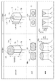
図7は、従来のアーク放電による溶接(TIG溶接)と、本実施形態のレーザー溶接とを比較する図である。両方式共に、接合対象導体となる2つのセグメント導体7は、裸導体端部7nの対向面同士が隣り合って対向すると共に、裸導体端部7nの先端同士が基準平面Prに沿って並ぶ状態で溶接される。この際、セグメント導体7は、導体端部7tの先端から予め規定された剥離長Lpの領域の絶縁被膜7hが除去されているが、TIG溶接を行う場合の剥離長“Lp2”に比べて、レーザー溶接を行う場合の剥離長“Lp1”の方が短い長さに設定可能である。上述したように、レーザー溶接では、溶接時におけるセグメント導体7(裸導体端部7n)の温度上昇を抑制することが可能であるから、TIG溶接を行う場合に比べて絶縁被膜7hへの影響が小さくなる。従って、絶縁被膜7hを溶融させないために必要となる剥離長Lpも、レーザー溶接を行う場合にはTIG溶接を行う場合に比べて短くすることができる。
FIG. 7 is a diagram comparing conventional welding by arc discharge (TIG welding) and laser welding according to the present embodiment. In both types, the two
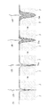
図7の中段及び下段には、溶接後のセグメント導体7を模式的に示している。TIG溶接を行った場合には、アークAKがセグメント導体7の先端部の比較的に広い範囲に印加され、当該先端部が全体的に溶融し、表面張力により先端部が丸みを帯びて凝固する。このため、基準平面Prに直交する方向(上面)から見た接合後の導体端部7tの先端の外縁が、接合前の2つの導体端部7tの先端の配置領域Sからはみ出してしまう。つまり、溶接前の導体端部7tの先端の輪郭線に対して、溶接後の輪郭線は部分的にはみ出した形状となる。このため、TIG溶接の場合には、隣接する接合対象導体の間の距離“Cp”をこのはみ出し量“Ms”の分だけ多くして、絶縁距離を確保できるようにする必要がある。これに対して、レーザー溶接の場合には、はみ出し量“Ms”を考慮する必要はないから、隣接する接合対象導体の間の距離“Cp”は相対的に短くなる。従って、レーザー溶接を用いた場合には、TIG溶接を用いた場合に比べて、コイル3を小型化することができる。即ち、本実施形態の接合方法を用いて形成されたコイル3は、基準平面Prに直交する方向から見て、接合前の2つの導体端部7tの先端の配置領域Sの内側に、接合後の導体端部7tの先端の外縁がはみ出すことなく、収まっている。即ち、配置領域Sに対応する2つの導体端部7tの先端の外縁が接合の前後で変化しない。尚、配置領域Sとは、対向面Poを除いた2つの導体端部7tの先端面の外縁をつないで構成される閉領域であり、2つの先端面が占める領域と、それらに挟まれた領域(セグメント導体7同士の間に隙間が生じている場合の当該隙間に対応する領域)とを合わせた領域である。
The middle and lower stages of FIG. 7 schematically show the
また、上述したように、TIG溶接を行った場合には、セグメント導体7の先端部が全体的に溶融し、表面張力により先端部が丸みを帯びて凝固する。従って、溶接後のセグメント導体7の導体端部7tは、図7の下段の側面図に示すように、その延在方向に沿って基準平面Prよりも延伸量“Mu”だけ延伸する場合がある。このため、セグメント導体7は、導体端部7tにおいて、延伸量“Mu”だけ長くなる可能性がある。さらに、上述したように、絶縁被膜7hの剥離長Lpは、溶接に伴って上昇するセグメント導体7の温度が、絶縁被膜7hの耐軟化温度に達することが無いような長さに設定されている。レーザー溶接の場合の温度上昇は、TIG溶接の場合の温度上昇に比べて小さく、耐軟化距離Dhも、レーザー溶接の方がTIG溶接に比べて“ΔDh”だけ短い。上述したように、レーザー溶接の場合には、延伸量“Mu”も生じないので、溶接後の裸導体端部7nの長さは、TIG溶接を行った場合に比べて“ΔDh+Mu”だけ短くなる。裸導体端部7nの長さは、コイルエンドの長さに影響するので、レーザー溶接を用いた場合には、TIG溶接を用いる場合に比べてコイルエンドが短くなり、コイル3を小型化することができる。
As described above, when TIG welding is performed, the tip of the
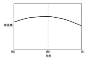
上述したように、レーザー照射工程#20におけるレーザーの照射角度(θc)は、基準平面Prに直交する照射基準軸Xcに対して6〜10[°](基準平面Prを基準とした照射角度(θp)は80〜86[°])である。図8は、実験により得られた照射角度(θc)と溶融領域7mの断面積との関係を示している。照射角度(θc)が、最適値(例えば、θB=8[°])の場合には、目標とする最大の断面積を得ることができ、良好に2つのセグメント導体7を接合することができる。一方、照射角度(θc)が、最適値から外れると、角度が大きくなっても小さくなっても、溶融領域7mの断面積は減少し、2つのセグメント導体7を接合する強度や導電性が低下する。
As described above, the laser irradiation angle (θc) in the laser
例えば、照射角度(θc)の最適値が“θB”の場合に、照射角度(θc)がより大きい角度“θL”であると、接合対象導体の内の一方の裸導体端部7nの対向面Poとレーザーの光軸Xoとの交点と基準平面Prとの距離である照射深さDbが、より浅い位置(基準平面Prから近い位置)となる。この場合、当該一方の裸導体端部7nの対向面Poに対するレーザーの入射角が深くなるので、当該一方の裸導体端部7nへ与えられるエネルギーが、他方の裸導体端部7nに比べて大きくなる。その結果、当該一方の裸導体端部7nの方が他方の裸導体端部7nに比べて溶融し易くなり、いわゆる片溶けが発生する。片溶けを生じた場合には、溶融領域7mが、片溶けを生じている裸導体端部7nの対向面Poとは反対側の側面(背面)にまで達する可能性がある。この場合には、レーザーによって与えられたエネルギー(加熱温度)が当該背面から拡散することになる。また、溶融領域7mが、片溶けを生じている一方の裸導体端部7nの背面にまで達しなかったとしても、他方の裸導体端部7nに伝搬するエネルギー(加熱温度)は想定的に少なくなる。従って、照射角度が最適値から離れ、照射深さDbが浅くなると、接合対象導体の全体としての溶融領域7mの断面積は減少する。
For example, when the optimum value of the irradiation angle (θc) is “θB” and the irradiation angle (θc) is a larger angle “θL”, the facing surface of one
これらのことから、本実施形態のように、セグメント導体7の断面形状が矩形状である場合、良好に形成されたコイル3は、以下のようなものとなる。即ち、好適なコイル3は、接合対象導体を構成する2つのセグメント導体7の対向面Poとは反対側の背面が、レーザー照射により導体材料が溶融していない非溶融範囲に含まれている状態で形成されている。
From these things, when the cross-sectional shape of the
一方、照射角度(θc)の最適値が“θB”の場合に、照射角度(θc)がより小さい角度“θS”であると、照射深さDbは、より深い位置(基準平面Prから遠い位置)となる。その結果、基準平面Prから遠い位置において溶融が始まることになるので、エネルギーが拡散して温度も拡散し、照射角度(θc)が“θB”の場合に比べて溶融領域7mの断面積が小さくなる。
On the other hand, when the optimum value of the irradiation angle (θc) is “θB” and the irradiation angle (θc) is a smaller angle “θS”, the irradiation depth Db is a deeper position (a position far from the reference plane Pr). ) As a result, since melting starts at a position far from the reference plane Pr, energy is diffused and temperature is also diffused, and the cross-sectional area of the melted
ところで、TIG溶接に比べてセグメント導体7の温度上昇が少ないレーザー溶接を用いた場合でも、レーザーの照射時間が長くなるとエネルギー量が増えて温度上昇も大きくなる。そこで、温度上昇を抑制しながら、必要な領域を溶融させるために、レーザー照射工程#20においてパルス照射が行われる。具体的には、図9に例示するように、予め規定された規定照射時間に亘ってレーザーを照射する照射フェーズPEと、予め規定された休止時間に亘ってレーザー照射を休止する休止フェーズPPとを繰り返すパルス照射によってレーザーが照射される。規定照射時間は、レーザーの照射を継続しても、裸導体端部7nと絶縁被膜7hとの境界部分におけるセグメント導体7の温度(被膜先端温度)が、絶縁被膜7hが溶融しないような温度に留まる時間に設定されると好適である。尚、絶縁被膜7hが溶融しないような温度とは、絶縁被膜7hが完全に溶融する温度ではなく、絶縁被膜7hが軟化して外観が変化する耐軟化温度であると好適である。
By the way, even when laser welding is used in which the temperature rise of the
図9に示す例では、3回の照射フェーズPEが設けられている。複数回の照射フェーズPEを通して、セグメント導体7を溶融させる必要があるので、照射フェーズPEの後の休止フェーズPPでは、当然ながら照射フェーズPEの開始前の温度まで減少しない。従って、各照射フェーズPEの規定照射時間が同一であれば、後で実行される照射フェーズPEにおける被膜先端温度の方が高くなる。つまり、図9における第1照射フェーズPE1よりも第2照射フェーズPE2の方が被膜先端温度が高くなり、第2照射フェーズPE2よりも第3照射フェーズPE3の方が被膜先端温度が高くなる。従って、規定照射時間は、最終の照射フェーズPE(図9に例示する形態では第3照射フェーズPE3)において、被膜先端運度が、絶縁被膜7hの融点或いは耐軟化温度に達しない範囲の時間に設定されると好適である。
In the example shown in FIG. 9, three irradiation phases PE are provided. Since it is necessary to melt the
尚、図9では、3回の照射フェーズPEが設定されているが、各照射フェーズPEにおける規定照射時間は同一であってもよいし、別個の値であってもよい。同様に、2回の休止フェーズPPにおける各休止時間も同一であってもよいし、別個の値であってもよい。また、当然ながら、照射フェーズPEの回数も3回に限定されるものではなく、5回等であってもよい。また、温度上昇が絶縁被膜7hの耐軟化温度の範囲内であれば、パルス照射が実施されず、1回の照射によって溶接が実施されてもよい。
In FIG. 9, three irradiation phases PE are set, but the prescribed irradiation time in each irradiation phase PE may be the same or may be a separate value. Similarly, the pause times in the two pause phases PP may be the same or may be different values. Of course, the number of irradiation phases PE is not limited to three, and may be five. Moreover, if the temperature rise is within the range of the softening temperature of the insulating
本発明は、セグメント導体を複数個用い、異なるセグメント導体の端部同士を接合して、回転電機のコイルを形成するために利用することができる。 The present invention can be used to form a coil of a rotating electrical machine by using a plurality of segment conductors and joining ends of different segment conductors.
3 :コイル
5 :周方向接続部(セグメント導体)
7 :セグメント導体
7a :基本セグメント導体(セグメント導体)
7h :絶縁被膜
7m :溶融領域
7n :裸導体端部
90 :接続部材(セグメント導体)
Lp :剥離長
PE :照射フェーズ
PP :休止フェーズ
Po :対向面
Pr :基準平面
#10 :導体保持工程
#20 :レーザー照射工程
3: Coil 5: Circumferential connection (segment conductor)
7:
7h: Insulating
Lp: peeling length PE: irradiation phase PP: rest phase Po: opposing surface Pr: reference plane # 10: conductor holding step # 20: laser irradiation step
Claims (7)
前記導体端部の先端から予め規定された剥離長の領域の前記絶縁被膜が除去された裸導体端部を有する前記セグメント導体を用い、接合対象導体となる2つの前記セグメント導体を、前記裸導体端部の対向面同士が隣り合って対向すると共に、前記裸導体端部の先端同士が基準平面に沿って並ぶ状態に保持する導体保持工程と、
前記基準平面に直交する方向に対して予め規定された角度で傾斜した照射角度で、前記裸導体端部の2つの対向面の一方にレーザーを照射して前記裸導体端部同士を溶接するレーザー照射工程と、
を備える回転電機の導体接合方法。 Using a plurality of segment conductors coated with an insulating film, in order to form a coil of a rotating electrical machine, a conductor joining method of a rotating electrical machine that joins the conductor ends that are the ends of the different segment conductors,
Using the segment conductor having the bare conductor end portion in which the insulating coating in the region of the predetermined peeling length is removed from the tip of the conductor end portion, the two segment conductors to be joined conductors are used as the bare conductor. The conductor holding step for holding the opposing surfaces of the end portions adjacent to each other, and holding the tips of the bare conductor end portions aligned along a reference plane;
Laser that irradiates a laser to one of two opposing surfaces of the bare conductor ends and welds the bare conductor ends to each other at an irradiation angle inclined at a predetermined angle with respect to a direction orthogonal to the reference plane Irradiation process;
A method for joining conductors of a rotating electrical machine.
前記導体端部の先端から予め規定された剥離長の領域の前記絶縁被膜が除去された裸導体端部を有する2つの前記セグメント導体を接合対象導体として、
前記裸導体端部の対向面同士が隣り合うと共に、前記裸導体端部の先端同士が基準平面に沿って並んだ状態で、前記裸導体端部の2つの対向面の一方に前記基準平面に直交する方向に対して予め規定された角度で傾斜した照射角度でレーザーを照射されて、2つの前記接合対象導体同士が接合されたものであり、
前記基準平面に直交する方向から見て、接合前の2つの前記導体端部の先端の配置領域の内側に、接合後の前記導体端部の先端の外縁が収まっている回転電機のコイル。 A coil of a rotating electrical machine formed by joining a plurality of segment conductors to which an insulating film has been applied, and joining the conductor ends that are the ends of the different segment conductors,
The two segment conductors having the bare conductor end portion from which the insulating coating in the region of the peeling length defined in advance from the tip end of the conductor end portion is removed as the conductors to be joined,
The opposing surfaces of the bare conductor end portions are adjacent to each other, and the tips of the bare conductor end portions are aligned along the reference plane, and the reference plane is placed on one of the two opposing surfaces of the bare conductor end portion. The laser is irradiated at an irradiation angle inclined at a predetermined angle with respect to the orthogonal direction, and the two conductors to be bonded are bonded to each other,
A coil of a rotating electrical machine in which the outer edge of the tip of the conductor end after joining is contained inside the arrangement region of the tip of the two conductor end before joining, as viewed from the direction orthogonal to the reference plane.
前記接合対象導体を構成する2つの前記セグメント導体の前記対向面とは反対側の背面は、レーザー照射により導体材料が溶融していない非溶融範囲に含まれている請求項6に記載の回転電機のコイル。
The segment conductor has a rectangular cross-sectional shape,
7. The rotating electrical machine according to claim 6, wherein the back surfaces of the two segment conductors constituting the bonding target conductor opposite to the facing surfaces are included in a non-melting range in which the conductor material is not melted by laser irradiation. Coil.
Priority Applications (1)
| Application Number | Priority Date | Filing Date | Title |
|---|---|---|---|
| JP2012139983A JP5958109B2 (en) | 2012-06-21 | 2012-06-21 | Conductor joining method for rotating electrical machine |
Applications Claiming Priority (1)
| Application Number | Priority Date | Filing Date | Title |
|---|---|---|---|
| JP2012139983A JP5958109B2 (en) | 2012-06-21 | 2012-06-21 | Conductor joining method for rotating electrical machine |
Publications (2)
| Publication Number | Publication Date |
|---|---|
| JP2014007795A true JP2014007795A (en) | 2014-01-16 |
| JP5958109B2 JP5958109B2 (en) | 2016-07-27 |
Family
ID=50105090
Family Applications (1)
| Application Number | Title | Priority Date | Filing Date |
|---|---|---|---|
| JP2012139983A Active JP5958109B2 (en) | 2012-06-21 | 2012-06-21 | Conductor joining method for rotating electrical machine |
Country Status (1)
| Country | Link |
|---|---|
| JP (1) | JP5958109B2 (en) |
Cited By (25)
| Publication number | Priority date | Publication date | Assignee | Title |
|---|---|---|---|---|
| WO2017051609A1 (en) * | 2015-09-25 | 2017-03-30 | 日立オートモティブシステムズ株式会社 | Rotating electric machine and method for manufacturing same |
| JP2018020340A (en) * | 2016-08-02 | 2018-02-08 | トヨタ自動車株式会社 | Laser welding method of flat wire |
| DE102016215031A1 (en) | 2016-08-11 | 2018-02-15 | Robert Bosch Gmbh | Stator of an electric machine |
| JP2018030155A (en) * | 2016-08-25 | 2018-03-01 | トヨタ自動車株式会社 | Laser welding method for flat wire |
| DE102017208706A1 (en) | 2016-09-27 | 2018-03-29 | Robert Bosch Gmbh | Stator for an electric machine |
| WO2018077511A1 (en) * | 2016-10-24 | 2018-05-03 | Robert Bosch Gmbh | Method for connecting flat wire ends and stator produced in such a way |
| CN108574353A (en) * | 2017-03-10 | 2018-09-25 | 丰田自动车株式会社 | The stator and its manufacturing device of electric rotating machine |
| WO2018233896A1 (en) | 2017-06-21 | 2018-12-27 | Robert Bosch Gmbh | STATOR FOR ELECTRIC MACHINE |
| JP2019089097A (en) * | 2017-11-14 | 2019-06-13 | トヨタ自動車株式会社 | Laser welding method for flat wire |
| CN109980823A (en) * | 2017-12-27 | 2019-07-05 | 丰田自动车株式会社 | The stator of rotating electric machine and the manufacturing method of stator coil |
| JP2019118159A (en) * | 2017-12-26 | 2019-07-18 | トヨタ自動車株式会社 | Welding method for segment conductor |
| US10439462B2 (en) | 2016-12-14 | 2019-10-08 | Toyota Jidosha Kabushiki Kaisha | Rotary electric machine |
| JP2020043706A (en) * | 2018-09-12 | 2020-03-19 | 本田技研工業株式会社 | Wire segment and stator |
| JP2020120451A (en) * | 2019-01-21 | 2020-08-06 | トヨタ自動車株式会社 | Coil joining method |
| JP2020142257A (en) * | 2019-03-05 | 2020-09-10 | 本田技研工業株式会社 | Laser welding method, laser welding equipment and rotary electric machine manufacturing method |
| CN111774728A (en) * | 2019-04-03 | 2020-10-16 | 通快激光与系统工程有限公司 | Stator copper wire welding method, controller, laser processing machine and readable program carrier |
| JP2021145473A (en) * | 2020-03-12 | 2021-09-24 | 株式会社アイシン | Method of manufacturing stator for rotary electric machine |
| JP2021145478A (en) * | 2020-03-12 | 2021-09-24 | 株式会社アイシン | Method of manufacturing stator for rotary electric machine |
| JP2021167169A (en) * | 2020-04-13 | 2021-10-21 | 住友ゴム工業株式会社 | Evaluation method of stone biting performance |
| JP2022524635A (en) * | 2019-03-12 | 2022-05-09 | トルンプフ レーザー- ウント ジュステームテヒニク ゲゼルシャフト ミット ベシュレンクテル ハフツング | Hairpin welding method and hairpin welding equipment |
| WO2022196823A1 (en) * | 2021-03-19 | 2022-09-22 | 株式会社アイシン | Method for manufacturing stator for rotating electrical machine |
| DE102022003824A1 (en) | 2022-10-17 | 2022-12-01 | Mercedes-Benz Group AG | Device for joining elongate component areas of winding elements of at least one winding of an electrical machine and use of such a device |
| DE102022003823A1 (en) | 2022-10-17 | 2022-12-01 | Mercedes-Benz Group AG | Process for connecting two pin-like component areas |
| JP2022182279A (en) * | 2021-05-28 | 2022-12-08 | 古河電気工業株式会社 | Laser welding method, laser welding device, and electric apparatus |
| WO2023054407A1 (en) * | 2021-09-29 | 2023-04-06 | 日本発條株式会社 | Stator manufacturing method |
Families Citing this family (1)
| Publication number | Priority date | Publication date | Assignee | Title |
|---|---|---|---|---|
| JP6674588B1 (en) | 2019-02-22 | 2020-04-01 | 株式会社東芝 | Method for welding copper-containing member and method for manufacturing rotating electric machine |
Citations (5)
| Publication number | Priority date | Publication date | Assignee | Title |
|---|---|---|---|---|
| JPH06261503A (en) * | 1993-03-04 | 1994-09-16 | Mitsubishi Electric Corp | Manufacture of rotor for inductor type ac generator |
| JPH07255151A (en) * | 1994-03-16 | 1995-10-03 | Matsushita Electric Ind Co Ltd | Laminated core fixing method |
| JP2000316259A (en) * | 1999-04-28 | 2000-11-14 | Denso Corp | End joining method for pair of conductors |
| JP2004519980A (en) * | 2001-02-28 | 2004-07-02 | ヴァレオ エキプマン エレクトリク モトゥール | Method of winding a rotor or stator winding of a rotating electrical device |
| JP2008154433A (en) * | 2006-12-20 | 2008-07-03 | Denso Corp | Winding joining method for rotating electrical machines |
-
2012
- 2012-06-21 JP JP2012139983A patent/JP5958109B2/en active Active
Patent Citations (5)
| Publication number | Priority date | Publication date | Assignee | Title |
|---|---|---|---|---|
| JPH06261503A (en) * | 1993-03-04 | 1994-09-16 | Mitsubishi Electric Corp | Manufacture of rotor for inductor type ac generator |
| JPH07255151A (en) * | 1994-03-16 | 1995-10-03 | Matsushita Electric Ind Co Ltd | Laminated core fixing method |
| JP2000316259A (en) * | 1999-04-28 | 2000-11-14 | Denso Corp | End joining method for pair of conductors |
| JP2004519980A (en) * | 2001-02-28 | 2004-07-02 | ヴァレオ エキプマン エレクトリク モトゥール | Method of winding a rotor or stator winding of a rotating electrical device |
| JP2008154433A (en) * | 2006-12-20 | 2008-07-03 | Denso Corp | Winding joining method for rotating electrical machines |
Cited By (55)
| Publication number | Priority date | Publication date | Assignee | Title |
|---|---|---|---|---|
| CN108141083A (en) * | 2015-09-25 | 2018-06-08 | 日立汽车系统株式会社 | Electric rotating machine and its manufacturing method |
| WO2017051609A1 (en) * | 2015-09-25 | 2017-03-30 | 日立オートモティブシステムズ株式会社 | Rotating electric machine and method for manufacturing same |
| EP3355445A4 (en) * | 2015-09-25 | 2019-05-22 | Hitachi Automotive Systems, Ltd. | ROTATING ELECTRIC MACHINE AND METHOD FOR MANUFACTURING THE SAME |
| CN108141083B (en) * | 2015-09-25 | 2020-04-21 | 日立汽车系统株式会社 | Rotary electric machine and method of making the same |
| JPWO2017051609A1 (en) * | 2015-09-25 | 2018-03-01 | 日立オートモティブシステムズ株式会社 | Rotating electric machine and manufacturing method thereof |
| US10523073B2 (en) | 2015-09-25 | 2019-12-31 | Hitachi Automotive Systems, Ltd. | Rotating electric machine and method of manufacturing same |
| CN107671420A (en) * | 2016-08-02 | 2018-02-09 | 丰田自动车株式会社 | The method for laser welding of lenticular wire |
| CN107671420B (en) * | 2016-08-02 | 2019-08-06 | 丰田自动车株式会社 | The method for laser welding of flat wire |
| JP2018020340A (en) * | 2016-08-02 | 2018-02-08 | トヨタ自動車株式会社 | Laser welding method of flat wire |
| WO2018028856A1 (en) | 2016-08-11 | 2018-02-15 | Robert Bosch Gmbh | Stator for an electrical machine |
| DE102016215031A1 (en) | 2016-08-11 | 2018-02-15 | Robert Bosch Gmbh | Stator of an electric machine |
| JP2018030155A (en) * | 2016-08-25 | 2018-03-01 | トヨタ自動車株式会社 | Laser welding method for flat wire |
| WO2018059831A1 (en) | 2016-09-27 | 2018-04-05 | Robert Bosch Gmbh | Stator for an electrical machine |
| DE102017208706A1 (en) | 2016-09-27 | 2018-03-29 | Robert Bosch Gmbh | Stator for an electric machine |
| US10749399B2 (en) | 2016-09-27 | 2020-08-18 | Robert Bosch Gmbh | Stator for an electrical machine |
| CN109792181A (en) * | 2016-09-27 | 2019-05-21 | 罗伯特·博世有限公司 | Stator for motor |
| US11101720B2 (en) | 2016-10-24 | 2021-08-24 | Robert Bosch Gmbh | Method for connecting flat wire ends and stator produced in such a way |
| WO2018077511A1 (en) * | 2016-10-24 | 2018-05-03 | Robert Bosch Gmbh | Method for connecting flat wire ends and stator produced in such a way |
| US10439462B2 (en) | 2016-12-14 | 2019-10-08 | Toyota Jidosha Kabushiki Kaisha | Rotary electric machine |
| US11557931B2 (en) | 2017-03-10 | 2023-01-17 | Toyota Jidosha Kabushiki Kaisha | Stator with dual jig arrangement |
| CN108574353B (en) * | 2017-03-10 | 2020-05-29 | 丰田自动车株式会社 | Stator of rotating electrical machine and its manufacturing device |
| CN108574353A (en) * | 2017-03-10 | 2018-09-25 | 丰田自动车株式会社 | The stator and its manufacturing device of electric rotating machine |
| WO2018233896A1 (en) | 2017-06-21 | 2018-12-27 | Robert Bosch Gmbh | STATOR FOR ELECTRIC MACHINE |
| DE102017210445A1 (en) | 2017-06-21 | 2018-12-27 | Robert Bosch Gmbh | Stator for an electric machine |
| JP2019089097A (en) * | 2017-11-14 | 2019-06-13 | トヨタ自動車株式会社 | Laser welding method for flat wire |
| JP2019118159A (en) * | 2017-12-26 | 2019-07-18 | トヨタ自動車株式会社 | Welding method for segment conductor |
| CN109980823A (en) * | 2017-12-27 | 2019-07-05 | 丰田自动车株式会社 | The stator of rotating electric machine and the manufacturing method of stator coil |
| CN109980823B (en) * | 2017-12-27 | 2021-02-19 | 丰田自动车株式会社 | Stator of rotating electric machine and method for manufacturing stator coil |
| US10978925B2 (en) | 2017-12-27 | 2021-04-13 | Toyota Jidosha Kabushiki Kaisha | Stator of rotary electric machine and method of manufacturing stator coil |
| JP2020043706A (en) * | 2018-09-12 | 2020-03-19 | 本田技研工業株式会社 | Wire segment and stator |
| CN110896257A (en) * | 2018-09-12 | 2020-03-20 | 本田技研工业株式会社 | Wire segments and stators |
| JP7084329B2 (en) | 2019-01-21 | 2022-06-14 | トヨタ自動車株式会社 | Coil joining method |
| JP2020120451A (en) * | 2019-01-21 | 2020-08-06 | トヨタ自動車株式会社 | Coil joining method |
| JP7103978B2 (en) | 2019-03-05 | 2022-07-20 | 本田技研工業株式会社 | Laser welding method, laser welding equipment and manufacturing method of rotary electric machine |
| JP2020142257A (en) * | 2019-03-05 | 2020-09-10 | 本田技研工業株式会社 | Laser welding method, laser welding equipment and rotary electric machine manufacturing method |
| JP7280377B2 (en) | 2019-03-12 | 2023-05-23 | トルンプフ レーザー- ウント ジュステームテヒニク ゲゼルシャフト ミット ベシュレンクテル ハフツング | Hairpin Welding Method and Hairpin Welding Equipment |
| JP2022524635A (en) * | 2019-03-12 | 2022-05-09 | トルンプフ レーザー- ウント ジュステームテヒニク ゲゼルシャフト ミット ベシュレンクテル ハフツング | Hairpin welding method and hairpin welding equipment |
| CN111774728A (en) * | 2019-04-03 | 2020-10-16 | 通快激光与系统工程有限公司 | Stator copper wire welding method, controller, laser processing machine and readable program carrier |
| CN111774728B (en) * | 2019-04-03 | 2022-07-05 | 通快激光与系统工程有限公司 | Stator copper wire welding method, controller, laser processing machine and readable program carrier |
| JP7460403B2 (en) | 2020-03-12 | 2024-04-02 | 株式会社アイシン | Manufacturing method of a stator for a rotating electric machine |
| JP2021145473A (en) * | 2020-03-12 | 2021-09-24 | 株式会社アイシン | Method of manufacturing stator for rotary electric machine |
| JP7410757B2 (en) | 2020-03-12 | 2024-01-10 | 株式会社アイシン | Stator manufacturing method for rotating electric machines |
| JP2021145478A (en) * | 2020-03-12 | 2021-09-24 | 株式会社アイシン | Method of manufacturing stator for rotary electric machine |
| JP7484364B2 (en) | 2020-04-13 | 2024-05-16 | 住友ゴム工業株式会社 | Method for evaluating stone-biting performance |
| JP2021167169A (en) * | 2020-04-13 | 2021-10-21 | 住友ゴム工業株式会社 | Evaluation method of stone biting performance |
| JP7478697B2 (en) | 2021-03-19 | 2024-05-07 | 株式会社アイシン | Manufacturing method of a stator for a rotating electric machine |
| JP2022144424A (en) * | 2021-03-19 | 2022-10-03 | 株式会社アイシン | Manufacturing method for rotary electric machine stator |
| WO2022196823A1 (en) * | 2021-03-19 | 2022-09-22 | 株式会社アイシン | Method for manufacturing stator for rotating electrical machine |
| JP7665419B2 (en) | 2021-05-28 | 2025-04-21 | 古河電気工業株式会社 | Laser Welding Method |
| JP2022182279A (en) * | 2021-05-28 | 2022-12-08 | 古河電気工業株式会社 | Laser welding method, laser welding device, and electric apparatus |
| WO2023054407A1 (en) * | 2021-09-29 | 2023-04-06 | 日本発條株式会社 | Stator manufacturing method |
| WO2024083655A1 (en) | 2022-10-17 | 2024-04-25 | Mercedes-Benz Group AG | Device for joining elongate component regions of winding elements of at least one winding of an electric machine, and use of such a device |
| WO2024083656A1 (en) | 2022-10-17 | 2024-04-25 | Mercedes-Benz Group AG | Method for connecting two pin-shaped component regions |
| DE102022003823A1 (en) | 2022-10-17 | 2022-12-01 | Mercedes-Benz Group AG | Process for connecting two pin-like component areas |
| DE102022003824A1 (en) | 2022-10-17 | 2022-12-01 | Mercedes-Benz Group AG | Device for joining elongate component areas of winding elements of at least one winding of an electrical machine and use of such a device |
Also Published As
| Publication number | Publication date |
|---|---|
| JP5958109B2 (en) | 2016-07-27 |
Similar Documents
| Publication | Publication Date | Title |
|---|---|---|
| JP5958109B2 (en) | Conductor joining method for rotating electrical machine | |
| JP6086226B2 (en) | Conductor joining method for rotating electrical machine | |
| JP2014007794A (en) | Method for bonding conductor of rotary electric machine and coil of rotary electric machine | |
| CN110977160B (en) | Laser welding method of stator coil | |
| JP7107791B2 (en) | Coil wire laser welding method | |
| JP6593280B2 (en) | Laser welding method for flat wire | |
| JP2013109948A (en) | Joining structure and joining method for rectangular wires | |
| JP2019118159A (en) | Welding method for segment conductor | |
| JP7063693B2 (en) | Flat wire laser welding method | |
| US12508669B2 (en) | Method for welding copper-including members, and method for manufacturing electrical rotating machine | |
| CN108781029A (en) | The manufacturing method of rotor | |
| JP7335420B2 (en) | Stator manufacturing method for rotary electric machine | |
| US12431775B2 (en) | Stator manufacturing method | |
| CN115136475B (en) | Method for manufacturing stator for rotating electric machine | |
| JP7181171B2 (en) | How to join conductors | |
| WO2022196821A1 (en) | Method of producing stator for rotating electrical machine | |
| JP2019140839A (en) | Manufacturing method for rotary electric machine | |
| JP2018121396A (en) | Manufacturing method for coil | |
| US20230396135A1 (en) | Method for manufacturing stator for rotating electrical machine | |
| JP7478697B2 (en) | Manufacturing method of a stator for a rotating electric machine | |
| JP5823162B2 (en) | Wire conductor welding method | |
| WO2024080097A1 (en) | Rotating electric machine stator manufacturing method and rotating electric machine stator manufacturing device | |
| CN115940531A (en) | Method for producing active components, rotating electrical machine active components, and rotating electrical machines | |
| WO2021059426A1 (en) | Coil, and dynamo-electric machine | |
| JP7478699B2 (en) | Manufacturing method of a stator for a rotating electric machine |
Legal Events
| Date | Code | Title | Description |
|---|---|---|---|
| A621 | Written request for application examination |
Free format text: JAPANESE INTERMEDIATE CODE: A621 Effective date: 20150115 |
|
| A131 | Notification of reasons for refusal |
Free format text: JAPANESE INTERMEDIATE CODE: A131 Effective date: 20151124 |
|
| A977 | Report on retrieval |
Free format text: JAPANESE INTERMEDIATE CODE: A971007 Effective date: 20151125 |
|
| A521 | Request for written amendment filed |
Free format text: JAPANESE INTERMEDIATE CODE: A523 Effective date: 20160125 |
|
| TRDD | Decision of grant or rejection written | ||
| A01 | Written decision to grant a patent or to grant a registration (utility model) |
Free format text: JAPANESE INTERMEDIATE CODE: A01 Effective date: 20160524 |
|
| A61 | First payment of annual fees (during grant procedure) |
Free format text: JAPANESE INTERMEDIATE CODE: A61 Effective date: 20160606 |
|
| R150 | Certificate of patent or registration of utility model |
Ref document number: 5958109 Country of ref document: JP Free format text: JAPANESE INTERMEDIATE CODE: R150 |