JP2014008535A - ピストンリング組付装置 - Google Patents
ピストンリング組付装置 Download PDFInfo
- Publication number
- JP2014008535A JP2014008535A JP2012144167A JP2012144167A JP2014008535A JP 2014008535 A JP2014008535 A JP 2014008535A JP 2012144167 A JP2012144167 A JP 2012144167A JP 2012144167 A JP2012144167 A JP 2012144167A JP 2014008535 A JP2014008535 A JP 2014008535A
- Authority
- JP
- Japan
- Prior art keywords
- piston
- ring
- holding
- piston ring
- ring groove
- Prior art date
- Legal status (The legal status is an assumption and is not a legal conclusion. Google has not performed a legal analysis and makes no representation as to the accuracy of the status listed.)
- Granted
Links
- 238000004519 manufacturing process Methods 0.000 description 4
- 230000002093 peripheral effect Effects 0.000 description 4
- 238000000034 method Methods 0.000 description 3
- 230000002452 interceptive effect Effects 0.000 description 2
- 238000012423 maintenance Methods 0.000 description 2
- 239000000567 combustion gas Substances 0.000 description 1
- 238000002485 combustion reaction Methods 0.000 description 1
- 239000000446 fuel Substances 0.000 description 1
Images




Landscapes
- Automatic Assembly (AREA)
Abstract
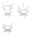
【解決手段】ピストンPのリング溝P3をピストンリングRに対して位置決めする際に、ピストンPの頂面P4を基準とするのではなく、ピストンPに設けられたコンロッド取付用のピン穴P1を基準とする。
【選択図】図4
Description
10 ピストン保持部
11 保持ピン
12 回転規制部
13 ストッパ
14 アーム
20 リング保持部
21 本体部
21a 穴
21b リング通路
22 シャッター
P ピストン
P1 ピン穴
P2 スカート部
P3 リング溝
P4 頂面
R ピストンリング
Claims (3)
- ピストンに設けられた一対のピン穴に保持ピンを挿入することにより前記ピストンを保持するピストン保持部と、ピストンリングを拡径状態で保持するリング保持部と、前記ピストン及び前記ピストンリングを同軸上に配置した状態で、前記ピストン保持部を前記リング保持部に対して軸方向に移動させる駆動部とを備え、
前記駆動部で前記ピストン保持部を軸方向に相対移動させて前記ピストンを前記ピストンリングの内周に挿入することにより、前記ピストンリングに対して前記ピストンのリング溝を位置決めし、前記リング保持部による前記ピストンリングの拡径状態を解除して前記ピストンリングを縮径させることにより、前記リング溝に前記ピストンリングを組み付けるピストンリング組付装置であって、
前記一対のピン穴を基準として、前記ピストンリングに対する前記リング溝の位置決めを行うことを特徴とするピストンリング組付装置。 - 前記ピストン保持部に、前記保持ピンを前記ピン穴に挿入した状態で前記ピストンのスカート部の端面に当接する回転規制部を設けた請求項1記載のピストンリング組付装置。
- 前記ピストン保持部にストッパを設けると共に、前記リング保持部にストッパ受けを設け、前記ストッパと前記ストッパ受けとを軸方向で当接させることにより、前記ピストンリングに対する前記リング溝の位置決めを行う請求項1記載のピストンリング組付装置。
Priority Applications (1)
| Application Number | Priority Date | Filing Date | Title |
|---|---|---|---|
| JP2012144167A JP6012096B2 (ja) | 2012-06-27 | 2012-06-27 | ピストンリング組付装置 |
Applications Claiming Priority (1)
| Application Number | Priority Date | Filing Date | Title |
|---|---|---|---|
| JP2012144167A JP6012096B2 (ja) | 2012-06-27 | 2012-06-27 | ピストンリング組付装置 |
Publications (2)
| Publication Number | Publication Date |
|---|---|
| JP2014008535A true JP2014008535A (ja) | 2014-01-20 |
| JP6012096B2 JP6012096B2 (ja) | 2016-10-25 |
Family
ID=50105673
Family Applications (1)
| Application Number | Title | Priority Date | Filing Date |
|---|---|---|---|
| JP2012144167A Active JP6012096B2 (ja) | 2012-06-27 | 2012-06-27 | ピストンリング組付装置 |
Country Status (1)
| Country | Link |
|---|---|
| JP (1) | JP6012096B2 (ja) |
Citations (3)
| Publication number | Priority date | Publication date | Assignee | Title |
|---|---|---|---|---|
| JPS63150119A (ja) * | 1986-12-15 | 1988-06-22 | Isuzu Motors Ltd | ピストンリング組付装置 |
| JPH01103238A (ja) * | 1987-10-12 | 1989-04-20 | Honda Motor Co Ltd | ピストンリング組込装置 |
| JPH05220631A (ja) * | 1991-07-31 | 1993-08-31 | Floquet Monopole | 自動ピストンリング装着装置 |
-
2012
- 2012-06-27 JP JP2012144167A patent/JP6012096B2/ja active Active
Patent Citations (3)
| Publication number | Priority date | Publication date | Assignee | Title |
|---|---|---|---|---|
| JPS63150119A (ja) * | 1986-12-15 | 1988-06-22 | Isuzu Motors Ltd | ピストンリング組付装置 |
| JPH01103238A (ja) * | 1987-10-12 | 1989-04-20 | Honda Motor Co Ltd | ピストンリング組込装置 |
| JPH05220631A (ja) * | 1991-07-31 | 1993-08-31 | Floquet Monopole | 自動ピストンリング装着装置 |
Also Published As
| Publication number | Publication date |
|---|---|
| JP6012096B2 (ja) | 2016-10-25 |
Similar Documents
| Publication | Publication Date | Title |
|---|---|---|
| US20110023277A1 (en) | Device and method for assembling retainer and cotter | |
| US9925632B2 (en) | Alignment device for assembling components and method of use | |
| CN103934667A (zh) | 用于定位多个功能元件的装置 | |
| RU2623343C1 (ru) | Оболочка | |
| JP2012040658A (ja) | 位置決め装置 | |
| WO2014112195A1 (ja) | ピストンの組み付け方法及び組み付け装置 | |
| JP6012096B2 (ja) | ピストンリング組付装置 | |
| HRP20250387T1 (hr) | Postupak za izradu kuglastog ventila za regulaciju tekućine, kuglasti ventil i alat za zavarivanje za držanje i rukovanje dijelovima ventila | |
| JP5224596B2 (ja) | リテーナコッタ組付方法 | |
| US8875668B2 (en) | Apparatus configured to shelter oil-jet device from inadvertent installation damage | |
| CN105856153A (zh) | 一种油封压装夹具及其使用方法 | |
| US10150268B2 (en) | Bead ring manufacturing device | |
| EP2191913A1 (en) | Casting mold device | |
| US10760450B2 (en) | Gas turbine and method for replacing bearing thereof | |
| FI128293B (en) | STICK INSTALLATION TOOL AND METHOD FOR MANUFACTURING A RETRACTED TIRE | |
| US10711665B2 (en) | Method for assembling a camshaft in a module body | |
| JP5816602B2 (ja) | ピストンの組み付け方法及び組み付け装置 | |
| KR102243074B1 (ko) | 캠샤프트 캐리어의 저널부 동시가공을 위한 고정지그 | |
| CN222177565U (zh) | 一种密封胶圈安装装置 | |
| CN111946460B (zh) | 用于航空发动机风扇组合件装配的导正装置及装配方法 | |
| JP2015230043A (ja) | 組立カムシャフトの製造方法 | |
| JP2016016494A (ja) | 被装着部材の装着装置および装着方法 | |
| US20140360014A1 (en) | Method for producing a built hollow valve of an internal combustion engine | |
| JP5442043B2 (ja) | 直噴インジェクタユニットの組付方法及び組付装置 | |
| CN102284922A (zh) | 浮动式卡簧涨套 |
Legal Events
| Date | Code | Title | Description |
|---|---|---|---|
| A621 | Written request for application examination |
Free format text: JAPANESE INTERMEDIATE CODE: A621 Effective date: 20150525 |
|
| A131 | Notification of reasons for refusal |
Free format text: JAPANESE INTERMEDIATE CODE: A131 Effective date: 20160325 |
|
| A521 | Request for written amendment filed |
Free format text: JAPANESE INTERMEDIATE CODE: A523 Effective date: 20160418 |
|
| TRDD | Decision of grant or rejection written | ||
| A01 | Written decision to grant a patent or to grant a registration (utility model) |
Free format text: JAPANESE INTERMEDIATE CODE: A01 Effective date: 20160916 |
|
| A61 | First payment of annual fees (during grant procedure) |
Free format text: JAPANESE INTERMEDIATE CODE: A61 Effective date: 20160916 |
|
| R150 | Certificate of patent or registration of utility model |
Ref document number: 6012096 Country of ref document: JP Free format text: JAPANESE INTERMEDIATE CODE: R150 |
|
| R250 | Receipt of annual fees |
Free format text: JAPANESE INTERMEDIATE CODE: R250 |
|
| R250 | Receipt of annual fees |
Free format text: JAPANESE INTERMEDIATE CODE: R250 |
|
| R250 | Receipt of annual fees |
Free format text: JAPANESE INTERMEDIATE CODE: R250 |
|
| R250 | Receipt of annual fees |
Free format text: JAPANESE INTERMEDIATE CODE: R250 |
|
| R250 | Receipt of annual fees |
Free format text: JAPANESE INTERMEDIATE CODE: R250 |
|
| R250 | Receipt of annual fees |
Free format text: JAPANESE INTERMEDIATE CODE: R250 |