JP2014018342A - Handheld cleaner - Google Patents
Handheld cleaner Download PDFInfo
- Publication number
- JP2014018342A JP2014018342A JP2012158411A JP2012158411A JP2014018342A JP 2014018342 A JP2014018342 A JP 2014018342A JP 2012158411 A JP2012158411 A JP 2012158411A JP 2012158411 A JP2012158411 A JP 2012158411A JP 2014018342 A JP2014018342 A JP 2014018342A
- Authority
- JP
- Japan
- Prior art keywords
- air
- fan
- port
- wall portion
- main body
- Prior art date
- Legal status (The legal status is an assumption and is not a legal conclusion. Google has not performed a legal analysis and makes no representation as to the accuracy of the status listed.)
- Pending
Links
Images


Landscapes
- Filtering Of Dispersed Particles In Gases (AREA)
Abstract
【課題】ブロワモードでも十分な吸引力を確保することができる手持ち式クリーナの提供
【解決手段】手持ち式クリーナ1は、ハウジング10と、モータ2と、ファン3と、フィルタ5とを備えている。ハウジング10には、吸込口12aと、排出口部11aと、吹き出し口16aが形成されていて、それらを繋ぐエア通路が設けられている。エア通路は、第1壁部14と第2壁部15とを備えている。第1壁部14は、モータ2の出力軸22の半径方向外方に延びることでファン3からのエアを半径方向外方に案内する。第2壁部15は、第1壁部14と接続し第1壁部14と交差する方向に延びファン3からのエアを略直線状に吹き出し口16aに案内する。
【選択図】図2
PROBLEM TO BE SOLVED: To provide a hand-held cleaner capable of ensuring a sufficient suction force even in a blower mode. . The housing 10 is formed with a suction port 12a, a discharge port portion 11a, and a blowout port 16a, and an air passage that connects them is provided. The air passage includes a first wall portion 14 and a second wall portion 15. The first wall portion 14 extends outward in the radial direction of the output shaft 22 of the motor 2 to guide the air from the fan 3 outward in the radial direction. The second wall portion 15 is connected to the first wall portion 14 and extends in a direction crossing the first wall portion 14 to guide the air from the fan 3 to the blowout port 16a in a substantially straight line shape.
[Selection] Figure 2
Description
本発明は手持ち式クリーナに関し、特にエア吸込口からエアの吸引が可能であり、エア吹き出し口からエアを吹き出し可能な手持ち式クリーナに関する。 The present invention relates to a hand-held cleaner, and more particularly to a hand-held cleaner capable of sucking air from an air suction port and capable of blowing air from an air outlet.
2次電池によって駆動される手持ち式クリーナとして、エア排気口からエアを排出する吸引モードと、エア吹き出し口からエアを排出するブロワモードと、を備える構造が知られている(特許文献1)。 As a hand-held cleaner driven by a secondary battery, a structure including a suction mode for discharging air from an air exhaust port and a blower mode for discharging air from an air outlet is known (Patent Document 1).
従来の手持ち式クリーナでは、吸引モードとブロワモードとでは排気通路が異なっており、ブロワモードでエアを排出する際に、通路の抵抗が大きいことで、吸引力が落ちていた。 In the conventional hand-held cleaner, the exhaust passage is different between the suction mode and the blower mode, and when the air is discharged in the blower mode, the suction force is reduced due to the large resistance of the passage.
そこで、本発明は、ブロワモードでも十分な吸引力を確保することができる手持ち式クリーナを提供することを目的とする。 Therefore, an object of the present invention is to provide a hand-held cleaner that can ensure a sufficient suction force even in the blower mode.
本発明では、エア吹き出し口と、エア吸引口と、前記エア吹き出し口と前記エア吸引口とを繋ぐエア通路と、が形成されたハウジングと、前記ハウジングに収容され、本体部と前記本体部から突出する出力軸とを有するモータと、前記エア通路内に配置され、前記出力軸に固定されて前記モータにより回転駆動されるファンと、前記エア通路内であって前記ファンと前記エア吸引口との間に設けられた集塵フィルタと、を有し、前記エア通路は、前記モータを支持し前記本体部と前記ファンとの間から前記出力軸の半径方向外方に延びることで前記ファンからのエアを前記半径方向外方に案内する第1壁部と、前記第1壁部と接続し前記第1壁部と交差する方向に延び前記ファンからのエアを略直線状に前記エア吹き出し口に案内する第2壁部と、を備えることを特徴とする手持ち式クリーナを提供している。 In the present invention, an air blowing port, an air suction port, an air passage connecting the air blowing port and the air suction port, a housing formed in the housing, A motor having a projecting output shaft, a fan disposed in the air passage, fixed to the output shaft and driven to rotate by the motor, the fan in the air passage, and the air suction port. A dust collecting filter provided between the fan and the air passage from the fan by supporting the motor and extending radially outward of the output shaft from between the main body and the fan. A first wall portion that guides the air outward in the radial direction, and extends in a direction intersecting with the first wall portion and intersecting the first wall portion. 2nd wall to guide Provides a portable cleaner, characterized in that it comprises a and.
このような構成により、ファンからのエアは第1壁部によって半径方向外方に案内されて第1壁部と交差する第2壁部により略直線状にエア吹き出し口に案内されるため、第1壁部と第2壁部との交差箇所でのエアの停滞するスペースが無く当該箇所での渦の発生が抑制される。これにより、エアをエア吹き出し口から吹き出すときの流路抵抗が低減され、吸引力を上げることができる。また、第2壁部はエアを直線状にエア吹き出し口に案内するため、流路抵抗の更なる低減が可能となる。 With such a configuration, air from the fan is guided radially outward by the first wall portion and guided to the air outlet by the second wall portion intersecting the first wall portion in a substantially straight line. There is no space where air stagnates at the intersection of the first wall and the second wall, and the generation of vortices at that location is suppressed. Thereby, the flow path resistance when air is blown out from the air outlet is reduced, and the suction force can be increased. Further, since the second wall portion guides the air to the air outlet in a straight line, the flow path resistance can be further reduced.
また、前記ハウジングには、前記エア吸引口から前記エア通路内に吸引されたエアの少なくとも一部を前記エア通路外へ排出するエア排気口が形成され、前記エア通路内に流入した前記エアの排出を前記エア排気口と前記エア吹き出し口との間で切替える切替部をさらに備えることが好ましい。 The housing is formed with an air exhaust port for discharging at least part of the air sucked into the air passage from the air suction port to the outside of the air passage, and the air that has flowed into the air passage is formed in the housing. It is preferable to further include a switching unit that switches the discharge between the air exhaust port and the air outlet.
このような構成によると、切替部を切替えることにより、エア排気口からエアを排出する吸引モードとエア吹き出し口からエアを排出するブロワモードとを切替えることができる。これにより、用途に応じてモードを切り替えることができる手持ち式クリーナを提供することができる。 According to such a configuration, by switching the switching unit, it is possible to switch between a suction mode for discharging air from the air exhaust port and a blower mode for discharging air from the air outlet. Thereby, the handheld cleaner which can switch a mode according to a use can be provided.
また、前記エア排気口は、前記ファンの半径方向外方に形成されていることが好ましい。 Moreover, it is preferable that the said air exhaust port is formed in the radial direction outer side of the said fan.
このような構成によると、エア排気口からエアを排出する吸引モード時の排気抵抗が低減されるため、吸引力が上がる。これにより、吸込み仕事率の向上を図ることができる。 According to such a configuration, since the exhaust resistance in the suction mode for discharging air from the air exhaust port is reduced, the suction force is increased. Thereby, the improvement of a suction work rate can be aimed at.
また、前記エア排気口の開口面積は、前記エア吹き出し口の開口面積よりも大きいが好ましい。 The opening area of the air exhaust port is preferably larger than the opening area of the air outlet.
このような構成によると、エア排気口からエアを排出する吸引モードのときには、エア吹き出し口からエアを排出するブロワモードのときよりも吸引力が上がる。これにより、吸引モード時の吸込み仕事率の向上を図ることができる。 According to such a configuration, the suction force is higher in the suction mode in which air is discharged from the air exhaust port than in the blower mode in which air is discharged from the air outlet. Thereby, the improvement of the suction work rate at the time of suction mode can be aimed at.
以上より本発明によると、ブロワモードでも十分な吸引力を確保することができる手持ち式クリーナを提供することができる。 As described above, according to the present invention, it is possible to provide a hand-held cleaner that can ensure a sufficient suction force even in the blower mode.
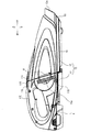
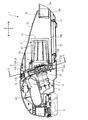
本発明の実施の形態による手持ち式クリーナ1について図1乃至図7を参照しながら説明する。図1、図2に示すように、手持ち式クリーナ1は、ハウジング10と、モータ2と、ファン3と、電池4と、集塵フィルタ5と、を備えている。以下の説明では図1における左側を手持ち式クリーナ1の後側、右側を手持ち式クリーナ1の前側と定義し、上側を手持ち式クリーナ1の上側、下側を手持ち式クリーナ1の下側と定義して説明する。また、図4における右側を手持ち式クリーナ1の左側、右側を手持ち式クリーナ1の左側と定義して説明する。
A handheld cleaner 1 according to an embodiment of the present invention will be described with reference to FIGS. As shown in FIGS. 1 and 2, the hand-held cleaner 1 includes a
ハウジング10は本体側ハウジング11とカバー側ハウジング12とにより構成されており、カバー側ハウジング12は本体側ハウジング11に対して着脱可能である。図2に示すように、カバー側ハウジング12は、エアを吹き出す吹き出し口16aが形成されたエア吹き出し管部16を備えている。本体側ハウジング11の下面には、カバー側ハウジング12と係合する係合部11Aが設けられている。本体側ハウジング11の上面には、押圧することによってカバー側ハウジング12と係合するラッチ部11Bが設けられている。本体側ハウジング11には、ラッチ部11Bの後部を上方に付勢するバネ11Cが設けられている。ラッチ部11Bの後部をバネ11Cの付勢力に抗して押圧すると、ラッチ部11Bの先端が上動して本体側ハウジング11とカバー側ハウジング12との係合が外れる。
The
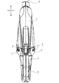
図1及び図3に示すように、本体側ハウジング11の左右方向側面には、それぞれ排気口部11aが形成されている。本体側ハウジング11の上部にはハンドル部11Eが設けられていて、ハンドル部11Eと本体側ハウジング11とはプラスチックで一体成型されている。ハンドル部11Eの前端部には、ユーザによって操作可能なトリガ13が設けられている。排気口部11aが本発明のエア排気口に相当する。
As shown in FIGS. 1 and 3,
図2に示すように、カバー側ハウジング12の下面には、係合部11Aと係合可能な被係合部12Aが設けられている。カバー側ハウジング12の上面には、ラッチ部11Bの先端部と係合するラッチ係合部12Bが設けられている。カバー側ハウジング12には、エアを吸込む吸込口12aが形成されている。本体側ハウジング11及びカバー側ハウジング12の詳細な構成は後述する。
As shown in FIG. 2, an engaged
モータ2は、本体側ハウジング11内であって前後方向における本体側ハウジング11の中央よりもやや前方の位置に本体側ハウジング11に支持されて設けられており、電池パック4及びトリガ13と電気的に接続されている。モータ2は本体部21と、本体部21から突出する出力軸22とから構成されている。本体部21及び出力軸22は、後方に向けて下がるように傾斜している。以下、モータ2の傾斜している方向をモータ傾斜方向Aという。
The
ファン3は遠心ファンであって、本体側ハウジング11の前端部の内部に配置されている。ファン3はモータ2の出力軸22に固定されており、ファン3は出力軸22と同軸的に一体で回転可能である。ファン3は、集塵フィルタ5を通過した空気をモータ傾斜方向Aから取込み出力軸22の半径方向外方に吐出している。
The
ファン3の半径方向外方には、図5(a)(b)及び図6に示すように、手持ち式クリーナ1のモードを吸引モードとブロワモードとを切り替える切替部31が設けられている。吸引モードでは吸引口12aから吸引したエアを排気口部11aから排出し、ブロワモードでは吸引口12aから吸引したエアを吹き出し口16aから吹き出す。吸引モードでは、排気口部11aの開口面積が吹き出し口16aよりも大きいため、強い吸引力を得ることができる。ブロワモードでは、排気口部11aからエアが排出されないため、周囲の粉塵を巻き上げることなく清掃を行うことができる。
As shown in FIGS. 5A and 5B and FIG. 6, a
切替部31には、半径方向外方に突出する2つのツマミ32がファン3を挟んで180°対向する位置に設けられていて、ツマミ32を把持して切替部31を回動させることにより、モードを切り替えることができる。切替部31には、半径方向に貫通する通気口部31aがファン3を挟んで180°対向する位置に形成されている。通気口部31aは、複数の通気口31bから構成されていて、複数の通気口31bの間にはリブ31Aが設けられている。これにより、切替部31の強度を維持しつつ通気口31bの開口面積を広く確保できる。
The
吸引モードのときは、図5(a)に示すように、各通気口部31aがそれぞれ排気口部11aと対向しており、ファン3からのエアは直接排気口部11aから外部に排出される。ブロワモードのときは、図5(b)に示すように、1の通気口部31aが吹き出し口16aと連通している後述の通路部15aと連通し、他の通気口部31aはカバー側ハウジング12によって塞がれる。通気口部31aが形成されている円周方向の距離は、通路15aの円周方向に沿った距離よりも長い。つまり、ブロワモード時には、通路部15aの円周方向全面に亘って通気口部31aが位置している。これにより、ブロワモード時の流路抵抗を低減できる。また、ブロワモード時は1つの通気口部31aは閉塞されているのに対し、吸引モード時は2つの通気口部31aが開口しているため、吸引モードのほうがより強い吸引力を得ることができる。
In the suction mode, as shown in FIG. 5A, each
電池パック4は、本体側ハウジング11の後端部の下部に着脱可能に設けられていて、内部にリチウムイオン電池セルが収容されている。
The battery pack 4 is detachably provided at the lower part of the rear end portion of the main
図2に示すように、カバー側ハウジング12内には集塵フィルタ5が設けられている。集塵フィルタ5は、外郭をなす金属製メッシュのプレフィルタ51と、プレフィルタ51の内側に位置する不織布から成る濾材52と、濾材52の内側に位置し濾材52が内側に潰れることを防止する補強部53と、プレフィルタ51と濾材52とをカバー側ハウジング12に固定する固定部54と、から構成されている。プレフィルタ51と濾材52とは、本体側ハウジング11と固定部54との間に挟持されることにより、本体側ハウジング11に固定されている。固定部54を本体側ハウジング11から取外すことにより、プレフィルタ51及び濾材52を交換することができる。補強部53は、本体側ハウジング11に対して着脱可能に構成されている。
As shown in FIG. 2, a
次に、本体側ハウジング11及びカバー側ハウジング12の詳細な構成について述べる。図1に示すように、本体側ハウジング11の前端部は、側面視において、上下方向から後方に傾斜している。以下、前端部の傾斜している方向を傾斜方向Bとする。傾斜方向Bはモータ傾斜方向Aと略直交している。排気口部11aは、図3に示すように、左右方向それぞれに形成されているが、両者は略同一の構成であるため、以下、一方の排気口部11aについてのみ説明する。排気口部11aは、ファン3及び切替部31の半径方向外方に傾斜方向Bと平行に形成されている。詳細には、排気口部11aは、図5(a)及び図5(b)に示すように、出力軸22を中心に約90°に亘って形成されている。側面視において排気口部11aはファン3と重複する位置に形成されており、ファン3は排気口部11aの近傍に位置していることから、ファン3からの排気は流路抵抗が少ないまま排気口部11aから外部に排出される。これにより、吸引モード時に強い吸引力を確保することができる。
Next, detailed configurations of the main
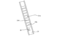
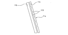
図7に示すように、排気口部11aは、傾斜方向Bに延びツマミ32が突出する長穴11bと、傾斜方向Bに沿って複数形成された排気穴11cとから構成されている。長穴11bが形成されていることにより、ツマミ32を操作するスペースを確保するとともに、排気口部11aの開口面積を広く確保できる。長穴11bと排気穴11cとの間及び各排気穴11c同士の間には、複数のリブ部11Dが規定されている。リブ部11Dが規定されていることにより、排気口部11aは開口面積を広く確保しつつ本体側ハウジング11の強度低下を抑えることができる。
As shown in FIG. 7, the
本体側ハウジング11内には、モータ2を支持しつつファン3から排出されたエアを案内する第1壁部14及び第2壁部15が規定されている。第1壁部14は、モータ2の本体部21とファン3との間から出力軸22の半径方向外方に向かって直線状に延び、ファン3からのエアを半径方向外方に案内している。このため、第1壁部14近傍にはファン3から排出されたエアが留まるスペースが無くなり、当該スペースに発生した渦によって流路抵抗が増加することが抑制される。
A
第2壁部15は、本体側ハウジング11の下面の一部であって、第1壁部14に接続するとともに第1壁部14と交差する方向、具体的には略水平方向(前後方向)に延びている。第1壁部14及び第2壁部15は、ファン3からのエアをファン3の半径方向から略水平方向に案内する通路部15aを構成している。当該通路部15aにより、ファン3から半径方向外方に排出されたエアは略直角に屈曲されて前方に向けて案内される。第2壁部15は、第1壁部14と略水平方向に交差しているため、第1壁部14と第2壁部15との接続箇所近傍ではファン3から排出されたエアが留まるスペースが無くなり、当該スペースに発生した渦によって流路抵抗が増加することが抑制される。
The
吸込口12aは、カバー側ハウジング12の前端部に形成されており、前方へ向けて開口する。吸込口12aはカバー側ハウジング12の内部と外部とを連通する貫通孔をなしている。吸込口12aは、集塵フィルタ5を介してファン3の周囲の空間に連通している。
The
エア吹き出し管部16は、カバー側ハウジング12とは別の部材で構成されており、ねじ17によってカバー側ハウジング12に取付け固定されている。エア吹き出し管部16はハウジング10の一部を構成している。吹き出し口16aは、本発明のエア吹き出し口に相当する。吸引口12aは、本発明のエア吸引口に相当する。
The air
エア吹き出し管部16の一端には、吸込口12aに隣接配置されて前方へ向けて開口する吹き出し口16aが形成されており、他端は、カバー側ハウジング12が本体側ハウジング11に固定されているときには、通路部15aに連通する。エア吹き出し管部16内には、一端と他端とを結ぶ直線状の管路16bが形成されている。管路16bは、ファン3から第1壁部14及び第2壁部15によって案内されたエアを直線状に吹き出し口16aに案内しているため、吹き出し口16aからエアを吹き出したときの流路抵抗が低減される。
At one end of the air blowing
図2に示すように、カバー側ハウジング12の内部であって吸込口12aの近傍には、吸込口12aと略同一形状の円盤状をしたゴム製の蓋部18が設けられている。蓋部18は、その周縁の上端がカバー側ハウジング12に支持されており、当該支持されている部分を中心として回動可能である。蓋部18は、蓋部18に外部から力が作用していないときには、図2に示すように吸込口12aが閉じられた状態となるように図示せぬバネにより付勢されている。手持ち式クリーナ1のユーザがトリガ13を操作することによりファン3が回転し始めると、カバー側ハウジング12内が負圧になり、蓋部18が回動して吸込口12aが開くように構成されている。
As shown in FIG. 2, a
次に、手持ち式クリーナ1の動作について説明する。強い吸引力が必要な場合は、手持ち式クリーナ1のユーザがツマミ32をつまんで切替部31を回転させ、図5(a)に示す状態(吸引モード)とする。ユーザがトリガ13を引くと、モータ2が回転駆動してファン3が回転する。これにより、吸込口12aからエアが流入し、当該エアは集塵フィルタ5によってエアと共に吸引した粉塵が捕獲され、エアのみがファン3へ流入する。ファン3からのエアは、図5(a)において矢印で示すように切替部31の通気口部31a及び排気口部11aを通り、本体側ハウジング11外部へ排出される。吸引モードでは、吸込口12aからカバー側ハウジング12内に流入したエアはその全てが排気口部11aから排出される。
Next, the operation of the handheld cleaner 1 will be described. When a strong suction force is required, the user of the hand-held cleaner 1 pinches the
吹き出し口16aからエアを吹き出すブロワを行う場合には、ユーザがツマミ32を操作して切替部31を回転させ、図5(b)に示す状態(ブロワモード)とする。ユーザがトリガ13を引くことにより、モータ2が回転駆動しファン3が回転する。これによって、吸込口12aからエアが流入し、当該エアは集塵フィルタ5を通過し、ファン3へ流入する。ファン3からのエアは、図5(b)において矢印で示すように切替部31の通気口部31aを通り、通路部15a及び管路16bを流れ、吹き出し口16aから吹き出される。ブロワモードでは、吸込口12aからカバー側本体内に流入したエアはその全てが吹き出し口16aから吹き出される。
When performing a blower that blows out air from the
また、吹き出し口16aから吹き出されるエアの量を弱めたい場合には、ユーザがツマミ32を操作して切替部31を図5(b)に示す状態から反時計回りに45°程回転させて、図5(a)に示す状態と図5(b)に示す状態との中間の状態とする。これにより、通気口部31aは排気口部11aと対向するとともに、通路部15aとも連通する。ユーザがトリガ13を引くことにより、モータ2が回転駆動しファン3が回転する。これにより、吸込口12aからエアが流入し、当該エアは集塵フィルタ5を通過し、ファン3へ流入する。ファン3からのエアの一部は、通路部15a及び管路16bを通って、吹き出し口16aから吹き出される。エアの残部は、排気口部11aから本体側ハウジング11外部へ排出される。この場合には、吸込口12aからカバー側本体内に流入したエアの一部が吹き出し口16aから吹き出されるため吹き出されるエアの量が弱まるとともに、残りのエアが排気口部11aから排気されるため吸引力が向上する。
If the user wants to reduce the amount of air blown from the
上述の3つの場合において吸込口12aから流入したエアが、吹き出し口16a又は排気口部11aから排出されるまでのエアの流れる流路はエア通路に相当する。
In the three cases described above, the flow path of the air until the air that has flowed in from the
このような構成によると、ファン3からのエアは第1壁部14によって半径方向外方に案内されて第1壁部14と交差する第2壁部15により略直線状に吹き出し口16aに案内されるため、第1壁部14と第2壁部15との交差箇所でのエアの停滞するスペースが無く当該箇所での渦の発生が抑制される。これにより、エアを吹き出し口16aから吹き出すときの流路抵抗が低減され、吸引力を上げることができる。また、第2壁部15はエアを直線状に吹き出し口16aに案内するため、流路抵抗の更なる低減が可能となる。
According to such a configuration, the air from the
また、切替部31を切替えることにより、吸引モードとブロワモードとを切替えることができる。これにより、用途に応じてモードを切り替えることができる手持ち式クリーナ1を提供することができる。
Moreover, the suction mode and the blower mode can be switched by switching the switching
また、排気口部11aはファン3の半径方向外方に形成されているため、吸引モード時の排気抵抗が低減され、吸引力が上がる。これにより、吸込み仕事率の向上を図ることができる。
Further, since the
また、排気口部11aの開口面積は吹き出し口16aの開口面積よりも広いため、吸引モードのときには、吹き出し口16aからエアを排出するブロワモードのときよりも吸引力が上がる。これにより、吸引モード時の吸込み仕事率の向上を図ることができる。
Further, since the opening area of the
本発明の手持ち式クリーナは、上述した実施の形態に限定されず、特許請求の範囲に記載した範囲で種々の変形や改良が可能である。 The hand-held cleaner of the present invention is not limited to the above-described embodiment, and various modifications and improvements can be made within the scope described in the claims.
上述の実施の形態では、エア吹き出し管部16をカバー側ハウジング12と別体としたが、カバー側ハウジング12と一体的に設けてもよい。
In the above-described embodiment, the air blowing
上述の実施の形態では、第1壁部14と第2壁部15とは交差していたが、交差する箇所にアールを設けてもよい。これによりさらなる流路抵抗の低減が可能となる。
In the above-described embodiment, the
1・・・手持ち式クリーナ 2・・モータ 3・・ファン 4・・電池パック 5・・集塵フィルタ 11・・本体側ハウジング 11a・・排気口 12・・カバー側ハウジング 13・・トリガ 14・・第1壁部 15・・第2壁部 16・・エア吹き出し管部 16a・・吹き出し口 21・・本体部 22・・出力軸
DESCRIPTION OF SYMBOLS 1 ... Hand-held
Claims (4)
前記ハウジングに収容され、本体部と前記本体部から突出する出力軸とを有するモータと、
前記エア通路内に配置され、前記出力軸に固定されて前記モータにより回転駆動されるファンと、
前記エア通路内であって前記ファンと前記エア吸引口との間に設けられた集塵フィルタと、を有し、
前記エア通路は、前記モータを支持し前記本体部と前記ファンとの間から前記出力軸の半径方向外方に延びることで前記ファンからのエアを前記半径方向外方に案内する第1壁部と、前記第1壁部と接続し前記第1壁部と交差する方向に延び前記ファンからのエアを略直線状に前記エア吹き出し口に案内する第2壁部と、を備えることを特徴とする手持ち式クリーナ。 A housing in which an air blowing port, an air suction port, and an air passage connecting the air blowing port and the air suction port are formed;
A motor housed in the housing and having a main body portion and an output shaft protruding from the main body portion;
A fan disposed in the air passage, fixed to the output shaft and driven to rotate by the motor;
A dust collection filter provided in the air passage and between the fan and the air suction port,
The air passage supports the motor and extends radially outward of the output shaft from between the main body and the fan, thereby guiding air from the fan outward in the radial direction. And a second wall portion connected to the first wall portion and extending in a direction intersecting the first wall portion to guide the air from the fan to the air outlet substantially linearly. Hand-held cleaner.
前記エア通路内に流入した前記エアの排出を前記エア排気口と前記エア吹き出し口との間で切替える切替部をさらに備えることを特徴とする請求項1の手持ち式クリーナ。 The housing is formed with an air exhaust port for discharging at least part of the air sucked into the air passage from the air suction port to the outside of the air passage,
The hand-held cleaner according to claim 1, further comprising a switching unit that switches discharge of the air that has flowed into the air passage between the air exhaust port and the air outlet.
Priority Applications (1)
| Application Number | Priority Date | Filing Date | Title |
|---|---|---|---|
| JP2012158411A JP2014018342A (en) | 2012-07-17 | 2012-07-17 | Handheld cleaner |
Applications Claiming Priority (1)
| Application Number | Priority Date | Filing Date | Title |
|---|---|---|---|
| JP2012158411A JP2014018342A (en) | 2012-07-17 | 2012-07-17 | Handheld cleaner |
Publications (1)
| Publication Number | Publication Date |
|---|---|
| JP2014018342A true JP2014018342A (en) | 2014-02-03 |
Family
ID=50193911
Family Applications (1)
| Application Number | Title | Priority Date | Filing Date |
|---|---|---|---|
| JP2012158411A Pending JP2014018342A (en) | 2012-07-17 | 2012-07-17 | Handheld cleaner |
Country Status (1)
| Country | Link |
|---|---|
| JP (1) | JP2014018342A (en) |
Cited By (1)
| Publication number | Priority date | Publication date | Assignee | Title |
|---|---|---|---|---|
| WO2017124628A1 (en) * | 2016-01-20 | 2017-07-27 | 江苏美的清洁电器股份有限公司 | Hand-held vacuum cleaner |
-
2012
- 2012-07-17 JP JP2012158411A patent/JP2014018342A/en active Pending
Cited By (2)
| Publication number | Priority date | Publication date | Assignee | Title |
|---|---|---|---|---|
| WO2017124628A1 (en) * | 2016-01-20 | 2017-07-27 | 江苏美的清洁电器股份有限公司 | Hand-held vacuum cleaner |
| US10575688B2 (en) | 2016-01-20 | 2020-03-03 | Jiangsu Midea Cleaning Appliances Co., Ltd. | Hand-held vacuum cleaner |
Similar Documents
| Publication | Publication Date | Title |
|---|---|---|
| JP2014068673A (en) | Handheld cleaner | |
| JP2016511671A (en) | Surface cleaning device | |
| CN108697292B (en) | Vacuum cleaner with a vacuum cleaner head | |
| JP5363958B2 (en) | Portable blower | |
| CN108697291B (en) | vacuum cleaner | |
| JP5541516B2 (en) | Handheld cleaner | |
| WO2012140825A1 (en) | Air suction/blower device and electric vacuum cleaner using same | |
| JP2014018342A (en) | Handheld cleaner | |
| JP2010274041A (en) | Electric vacuum cleaner | |
| JP5527484B2 (en) | Electric vacuum cleaner | |
| JP2008043792A (en) | Vacuum cleaner | |
| JP2002200016A (en) | Electric vacuum cleaner | |
| JP6111431B2 (en) | Electric vacuum cleaner | |
| JP2011172818A (en) | Vacuum cleaner | |
| JP2010268960A (en) | Electric vacuum cleaner | |
| JP4982175B2 (en) | Dust collector and vacuum cleaner | |
| JP2011024611A (en) | Electric vacuum cleaner | |
| JP6500687B2 (en) | Electric vacuum cleaner | |
| JP5907038B2 (en) | Electric vacuum cleaner | |
| JP6879793B2 (en) | Electric vacuum | |
| JP2020000562A (en) | Suction port body of vacuum cleaner and vacuum cleaner with the suction port body | |
| JP2018042584A (en) | Electric vacuum cleaner | |
| JP2018068590A (en) | Vacuum cleaner | |
| JP5329889B2 (en) | Electric vacuum cleaner | |
| JP5428641B2 (en) | Electric vacuum cleaner |