JP2014040718A - Electrically-driven construction machine - Google Patents
Electrically-driven construction machine Download PDFInfo
- Publication number
- JP2014040718A JP2014040718A JP2012182534A JP2012182534A JP2014040718A JP 2014040718 A JP2014040718 A JP 2014040718A JP 2012182534 A JP2012182534 A JP 2012182534A JP 2012182534 A JP2012182534 A JP 2012182534A JP 2014040718 A JP2014040718 A JP 2014040718A
- Authority
- JP
- Japan
- Prior art keywords
- external power
- plug
- connector
- connectors
- power supply
- Prior art date
- Legal status (The legal status is an assumption and is not a legal conclusion. Google has not performed a legal analysis and makes no representation as to the accuracy of the status listed.)
- Granted
Links
- 238000010276 construction Methods 0.000 title claims abstract description 14
- 238000001514 detection method Methods 0.000 claims abstract description 67
- 230000005540 biological transmission Effects 0.000 claims abstract description 28
- 238000010586 diagram Methods 0.000 description 11
- 239000003921 oil Substances 0.000 description 10
- 230000004044 response Effects 0.000 description 7
- 230000000694 effects Effects 0.000 description 6
- 230000008602 contraction Effects 0.000 description 5
- 238000000034 method Methods 0.000 description 5
- 230000005856 abnormality Effects 0.000 description 4
- 239000003638 chemical reducing agent Substances 0.000 description 4
- 230000007935 neutral effect Effects 0.000 description 4
- 238000012986 modification Methods 0.000 description 3
- 230000004048 modification Effects 0.000 description 3
- 230000002265 prevention Effects 0.000 description 3
- 230000008569 process Effects 0.000 description 3
- 230000001012 protector Effects 0.000 description 2
- HBBGRARXTFLTSG-UHFFFAOYSA-N Lithium ion Chemical compound [Li+] HBBGRARXTFLTSG-UHFFFAOYSA-N 0.000 description 1
- 230000008901 benefit Effects 0.000 description 1
- 239000010720 hydraulic oil Substances 0.000 description 1
- 229910001416 lithium ion Inorganic materials 0.000 description 1
- 230000007246 mechanism Effects 0.000 description 1
- 230000000630 rising effect Effects 0.000 description 1
- 239000002689 soil Substances 0.000 description 1
Images





Classifications
-
- B—PERFORMING OPERATIONS; TRANSPORTING
- B60—VEHICLES IN GENERAL
- B60L—PROPULSION OF ELECTRICALLY-PROPELLED VEHICLES; SUPPLYING ELECTRIC POWER FOR AUXILIARY EQUIPMENT OF ELECTRICALLY-PROPELLED VEHICLES; ELECTRODYNAMIC BRAKE SYSTEMS FOR VEHICLES IN GENERAL; MAGNETIC SUSPENSION OR LEVITATION FOR VEHICLES; MONITORING OPERATING VARIABLES OF ELECTRICALLY-PROPELLED VEHICLES; ELECTRIC SAFETY DEVICES FOR ELECTRICALLY-PROPELLED VEHICLES
- B60L53/00—Methods of charging batteries, specially adapted for electric vehicles; Charging stations or on-board charging equipment therefor; Exchange of energy storage elements in electric vehicles
-
- B—PERFORMING OPERATIONS; TRANSPORTING
- B60—VEHICLES IN GENERAL
- B60L—PROPULSION OF ELECTRICALLY-PROPELLED VEHICLES; SUPPLYING ELECTRIC POWER FOR AUXILIARY EQUIPMENT OF ELECTRICALLY-PROPELLED VEHICLES; ELECTRODYNAMIC BRAKE SYSTEMS FOR VEHICLES IN GENERAL; MAGNETIC SUSPENSION OR LEVITATION FOR VEHICLES; MONITORING OPERATING VARIABLES OF ELECTRICALLY-PROPELLED VEHICLES; ELECTRIC SAFETY DEVICES FOR ELECTRICALLY-PROPELLED VEHICLES
- B60L50/00—Electric propulsion with power supplied within the vehicle
- B60L50/50—Electric propulsion with power supplied within the vehicle using propulsion power supplied by batteries or fuel cells
- B60L50/51—Electric propulsion with power supplied within the vehicle using propulsion power supplied by batteries or fuel cells characterised by AC-motors
-
- B—PERFORMING OPERATIONS; TRANSPORTING
- B60—VEHICLES IN GENERAL
- B60L—PROPULSION OF ELECTRICALLY-PROPELLED VEHICLES; SUPPLYING ELECTRIC POWER FOR AUXILIARY EQUIPMENT OF ELECTRICALLY-PROPELLED VEHICLES; ELECTRODYNAMIC BRAKE SYSTEMS FOR VEHICLES IN GENERAL; MAGNETIC SUSPENSION OR LEVITATION FOR VEHICLES; MONITORING OPERATING VARIABLES OF ELECTRICALLY-PROPELLED VEHICLES; ELECTRIC SAFETY DEVICES FOR ELECTRICALLY-PROPELLED VEHICLES
- B60L50/00—Electric propulsion with power supplied within the vehicle
- B60L50/50—Electric propulsion with power supplied within the vehicle using propulsion power supplied by batteries or fuel cells
- B60L50/53—Electric propulsion with power supplied within the vehicle using propulsion power supplied by batteries or fuel cells in combination with an external power supply, e.g. from overhead contact lines
-
- E—FIXED CONSTRUCTIONS
- E02—HYDRAULIC ENGINEERING; FOUNDATIONS; SOIL SHIFTING
- E02F—DREDGING; SOIL-SHIFTING
- E02F3/00—Dredgers; Soil-shifting machines
- E02F3/04—Dredgers; Soil-shifting machines mechanically-driven
- E02F3/28—Dredgers; Soil-shifting machines mechanically-driven with digging tools mounted on a dipper- or bucket-arm, i.e. there is either one arm or a pair of arms, e.g. dippers, buckets
- E02F3/30—Dredgers; Soil-shifting machines mechanically-driven with digging tools mounted on a dipper- or bucket-arm, i.e. there is either one arm or a pair of arms, e.g. dippers, buckets with a dipper-arm pivoted on a cantilever beam, i.e. boom
- E02F3/32—Dredgers; Soil-shifting machines mechanically-driven with digging tools mounted on a dipper- or bucket-arm, i.e. there is either one arm or a pair of arms, e.g. dippers, buckets with a dipper-arm pivoted on a cantilever beam, i.e. boom working downwardly and towards the machine, e.g. with backhoes
- E02F3/325—Backhoes of the miniature type
-
- E—FIXED CONSTRUCTIONS
- E02—HYDRAULIC ENGINEERING; FOUNDATIONS; SOIL SHIFTING
- E02F—DREDGING; SOIL-SHIFTING
- E02F3/00—Dredgers; Soil-shifting machines
- E02F3/04—Dredgers; Soil-shifting machines mechanically-driven
- E02F3/96—Dredgers; Soil-shifting machines mechanically-driven with arrangements for alternate or simultaneous use of different digging elements
- E02F3/963—Arrangements on backhoes for alternate use of different tools
- E02F3/964—Arrangements on backhoes for alternate use of different tools of several tools mounted on one machine
-
- E—FIXED CONSTRUCTIONS
- E02—HYDRAULIC ENGINEERING; FOUNDATIONS; SOIL SHIFTING
- E02F—DREDGING; SOIL-SHIFTING
- E02F9/00—Component parts of dredgers or soil-shifting machines, not restricted to one of the kinds covered by groups E02F3/00 - E02F7/00
- E02F9/20—Drives; Control devices
- E02F9/2058—Electric or electro-mechanical or mechanical control devices of vehicle sub-units
- E02F9/2062—Control of propulsion units
- E02F9/207—Control of propulsion units of the type electric propulsion units, e.g. electric motors or generators
-
- E—FIXED CONSTRUCTIONS
- E02—HYDRAULIC ENGINEERING; FOUNDATIONS; SOIL SHIFTING
- E02F—DREDGING; SOIL-SHIFTING
- E02F9/00—Component parts of dredgers or soil-shifting machines, not restricted to one of the kinds covered by groups E02F3/00 - E02F7/00
- E02F9/20—Drives; Control devices
- E02F9/2058—Electric or electro-mechanical or mechanical control devices of vehicle sub-units
- E02F9/2091—Control of energy storage means for electrical energy, e.g. battery or capacitors
-
- E—FIXED CONSTRUCTIONS
- E02—HYDRAULIC ENGINEERING; FOUNDATIONS; SOIL SHIFTING
- E02F—DREDGING; SOIL-SHIFTING
- E02F9/00—Component parts of dredgers or soil-shifting machines, not restricted to one of the kinds covered by groups E02F3/00 - E02F7/00
- E02F9/20—Drives; Control devices
- E02F9/22—Hydraulic or pneumatic drives
- E02F9/2278—Hydraulic circuits
- E02F9/2285—Pilot-operated systems
-
- E—FIXED CONSTRUCTIONS
- E02—HYDRAULIC ENGINEERING; FOUNDATIONS; SOIL SHIFTING
- E02F—DREDGING; SOIL-SHIFTING
- E02F9/00—Component parts of dredgers or soil-shifting machines, not restricted to one of the kinds covered by groups E02F3/00 - E02F7/00
- E02F9/20—Drives; Control devices
- E02F9/22—Hydraulic or pneumatic drives
- E02F9/2278—Hydraulic circuits
- E02F9/2296—Systems with a variable displacement pump
-
- Y—GENERAL TAGGING OF NEW TECHNOLOGICAL DEVELOPMENTS; GENERAL TAGGING OF CROSS-SECTIONAL TECHNOLOGIES SPANNING OVER SEVERAL SECTIONS OF THE IPC; TECHNICAL SUBJECTS COVERED BY FORMER USPC CROSS-REFERENCE ART COLLECTIONS [XRACs] AND DIGESTS
- Y02—TECHNOLOGIES OR APPLICATIONS FOR MITIGATION OR ADAPTATION AGAINST CLIMATE CHANGE
- Y02T—CLIMATE CHANGE MITIGATION TECHNOLOGIES RELATED TO TRANSPORTATION
- Y02T10/00—Road transport of goods or passengers
- Y02T10/60—Other road transportation technologies with climate change mitigation effect
- Y02T10/70—Energy storage systems for electromobility, e.g. batteries
-
- Y—GENERAL TAGGING OF NEW TECHNOLOGICAL DEVELOPMENTS; GENERAL TAGGING OF CROSS-SECTIONAL TECHNOLOGIES SPANNING OVER SEVERAL SECTIONS OF THE IPC; TECHNICAL SUBJECTS COVERED BY FORMER USPC CROSS-REFERENCE ART COLLECTIONS [XRACs] AND DIGESTS
- Y02—TECHNOLOGIES OR APPLICATIONS FOR MITIGATION OR ADAPTATION AGAINST CLIMATE CHANGE
- Y02T—CLIMATE CHANGE MITIGATION TECHNOLOGIES RELATED TO TRANSPORTATION
- Y02T10/00—Road transport of goods or passengers
- Y02T10/60—Other road transportation technologies with climate change mitigation effect
- Y02T10/7072—Electromobility specific charging systems or methods for batteries, ultracapacitors, supercapacitors or double-layer capacitors
-
- Y—GENERAL TAGGING OF NEW TECHNOLOGICAL DEVELOPMENTS; GENERAL TAGGING OF CROSS-SECTIONAL TECHNOLOGIES SPANNING OVER SEVERAL SECTIONS OF THE IPC; TECHNICAL SUBJECTS COVERED BY FORMER USPC CROSS-REFERENCE ART COLLECTIONS [XRACs] AND DIGESTS
- Y02—TECHNOLOGIES OR APPLICATIONS FOR MITIGATION OR ADAPTATION AGAINST CLIMATE CHANGE
- Y02T—CLIMATE CHANGE MITIGATION TECHNOLOGIES RELATED TO TRANSPORTATION
- Y02T90/00—Enabling technologies or technologies with a potential or indirect contribution to GHG emissions mitigation
- Y02T90/10—Technologies relating to charging of electric vehicles
- Y02T90/14—Plug-in electric vehicles
Landscapes
- Engineering & Computer Science (AREA)
- Mining & Mineral Resources (AREA)
- Structural Engineering (AREA)
- General Engineering & Computer Science (AREA)
- Civil Engineering (AREA)
- Mechanical Engineering (AREA)
- Power Engineering (AREA)
- Transportation (AREA)
- Life Sciences & Earth Sciences (AREA)
- Sustainable Energy (AREA)
- Sustainable Development (AREA)
- Operation Control Of Excavators (AREA)
- Charge And Discharge Circuits For Batteries Or The Like (AREA)
- Electric Propulsion And Braking For Vehicles (AREA)
Abstract
Description
本発明は、電動式油圧ショベル等の電動式建設機械に係わり、特に、複数種類の外部電源のプラグがそれぞれ接続可能な複数のコネクタを備えた電動式建設機械に関する。 The present invention relates to an electric construction machine such as an electric hydraulic excavator, and more particularly to an electric construction machine provided with a plurality of connectors to which plugs of a plurality of types of external power sources can be respectively connected.
電動式建設機械の一つである電動式油圧ショベルは、例えば、電動モータと、この電動モータによって駆動される油圧ポンプと、複数の油圧アクチュエータ(詳細には、ブーム用油圧シリンダ、アーム用油圧シリンダ、及びバケット用油圧シリンダ等)と、油圧ポンプから複数の油圧アクチュエータへの圧油の流れをそれぞれ制御する複数の方向切換弁と、これら方向切換弁をそれぞれ操作する操作手段(詳細には、例えば、操作レバーの操作位置に応じてパイロット圧を生成し、このパイロット圧を方向切換弁の受圧部へ出力する操作装置)とを備えている。そして、運転者が操作手段で方向切換弁を操作すると、油圧ポンプから吐出された圧油が油圧アクチュエータに供給されて、油圧アクチュエータが駆動するようになっている。 An electric excavator that is one of electric construction machines includes, for example, an electric motor, a hydraulic pump driven by the electric motor, and a plurality of hydraulic actuators (specifically, a boom hydraulic cylinder and an arm hydraulic cylinder). And hydraulic cylinders for buckets), a plurality of directional control valves for controlling the flow of pressure oil from the hydraulic pump to the plurality of hydraulic actuators, and operating means for operating these directional control valves (in detail, for example, And an operation device that generates a pilot pressure in accordance with the operation position of the operation lever and outputs the pilot pressure to the pressure receiving portion of the direction switching valve. When the driver operates the direction switching valve with the operating means, the pressure oil discharged from the hydraulic pump is supplied to the hydraulic actuator so that the hydraulic actuator is driven.
このような電動式油圧ショベルにおいて、電動モータの電力源として内部バッテリ(車載バッテリ)を備えたものが知られている(例えば、特許文献1参照)。特許文献1に記載の電動式油圧ショベルは、さらに、チョッパ装置及びインバータを備えている。そして、内部バッテリからの電力によって電動モータを駆動する場合は、内部バッテリからの直流電力がチョッパ装置で昇圧され、さらにインバータで交流電力に変換されて、電動モータに供給されるようになっている。 In such an electric hydraulic excavator, one having an internal battery (vehicle-mounted battery) as a power source of the electric motor is known (for example, see Patent Document 1). The electric hydraulic excavator described in Patent Document 1 further includes a chopper device and an inverter. And when driving an electric motor with the electric power from an internal battery, the direct-current electric power from an internal battery is pressure | voltage-risen with a chopper apparatus, Furthermore, it converts into alternating current electric power with an inverter, and is supplied to an electric motor. .
また、特許文献1に記載の電動式油圧ショベルは、複数種類の外部電源のプラグがそれぞれ接続可能な複数のコネクタを備えている。そして、1つの外部電源のプラグがコネクタに接続されたときに、その外部電源からの電力によって内部バッテリを充電可能としている。このとき、例えば外部電源として三相交流200V電源がコネクタに接続された場合は、外部電源からの交流電力がチョッパ装置で直流電力に変換されるとともに降圧されて、内部バッテリに供給される。また、例えば外部電源として単相交流100V電源がコネクタに接続された場合は、外部電源からの交流電力がチョッパ装置で直流電力に変換されるとともに昇圧されて、内部バッテリに供給される。また、例えば外部電源として直流220V電源がコネクタに接続された場合は、外部電源からの直流電力がチョッパ装置で降圧されて、内部バッテリに供給されるようになっている。 The electric excavator described in Patent Document 1 includes a plurality of connectors to which a plurality of types of external power plugs can be connected. When a plug of one external power supply is connected to the connector, the internal battery can be charged by the power from the external power supply. At this time, for example, when a three-phase AC 200V power source is connected to the connector as an external power source, AC power from the external power source is converted into DC power by the chopper device and stepped down to be supplied to the internal battery. For example, when a single-phase AC 100V power source is connected to the connector as an external power source, AC power from the external power source is converted into DC power by the chopper device, boosted, and supplied to the internal battery. For example, when a DC 220V power source is connected to the connector as an external power source, the DC power from the external power source is stepped down by the chopper device and supplied to the internal battery.
従来技術では、例えば図15で示すように、三相交流200V電源100Aのプラグ101Aが接続可能なコネクタ102Aには送電系統103Aが接続され、単相交流100V電源100Bのプラグ101Bが接続可能なコネクタ102Bには送電系統103Bが接続され、直流電源100Cのプラグ101Cが接続可能なコネクタ102Cには送電系統103Cが接続されている。これら送電系統103A,103B,103Cには、ブレーカ104A,104B,104C(過電流保護器)がそれぞれ設けられている。制御装置105は、バッテリ装置106(詳細には、複数の内部バッテリ等を有するもの)からの電力を電動モータ107に供給して電動モータ107を駆動可能としている。また、コネクタ102A,102B,102Cのうちのいずれかが外部電源のプラグと接続された場合に、制御装置105は、外部電源から供給された電力をバッテリ装置107に供給可能としている。
In the prior art, as shown in FIG. 15, for example, a
ここで、制御装置105の小型化の観点から、図示のように、送電系統103A,103B,103Cは1つの共用系統108に合流してから、制御装置105に接続するように構成することが好ましい。この場合、運転者は、ブレーカ104A,104B,104Cのうち、外部電源が接続されるコネクタに対応したブレーカを閉状態とし、それ以外のブレーカ(すなわち、外部電源が接続されないコネクタに対応したブレーカ)を開状態となるように手動操作すればよい。しかし、運転者が間違えて、外部電源が接続されないコネクタに対応したブレーカも閉状態とする可能性がある。このような場合には、送電系統104A,104B,104Cの合流部を介して外部電源が接続されていないコネクタに電流が回り込んでしまう。
Here, from the viewpoint of miniaturization of the
本発明は、上記事柄に鑑みてなされたものであり、その目的は、送電系統の合流部を介して外部電源が接続されていないコネクタに電流が回り込むのを防止することができる電動式建設機械を提供することにある。 The present invention has been made in view of the above matters, and an object thereof is an electric construction machine capable of preventing current from flowing into a connector to which an external power source is not connected via a junction part of a power transmission system. Is to provide.
上記目的を達成するために、本発明は、電動モータと、前記電動モータによって駆動される油圧ポンプと、前記油圧ポンプから吐出された圧油により駆動される油圧アクチュエータと、前記電動モータの電力源である内部バッテリと、複数種類の外部電源のプラグがそれぞれ接続可能な複数のコネクタと、前記複数のコネクタにそれぞれ接続された複数の送電系統と、前記複数の送電系統が1つの共用系統を介して接続されたバッテリ充電部とを備え、前記バッテリ充電部は、前記複数のコネクタのうちのいずれかが前記外部電源のプラグと接続された場合に、前記外部電源から供給された電力を前記内部バッテリに供給する電動式建設機械において、前記複数の送電系統にそれぞれ設けられ、前記複数のコネクタにそれぞれ対応した複数の開閉器と、前記複数のコネクタのうちのいずれが前記外部電源のプラグと接続されたか、若しくは前記複数のコネクタのうちのいずれが前記外部電源のプラグと接続するために選択されたかを検出する検出部と、前記複数の開閉器のうち、前記検出部で検出されたコネクタに対応する開閉器を閉状態に、それ以外の開閉器を開状態に制御する開閉制御部とを備える。 To achieve the above object, the present invention provides an electric motor, a hydraulic pump driven by the electric motor, a hydraulic actuator driven by pressure oil discharged from the hydraulic pump, and a power source of the electric motor. An internal battery, a plurality of connectors to which a plurality of types of external power plugs can be respectively connected, a plurality of power transmission systems respectively connected to the plurality of connectors, and the plurality of power transmission systems via one common system Connected to the battery charging unit, and the battery charging unit receives power supplied from the external power source when any one of the plurality of connectors is connected to a plug of the external power source. In the electric construction machine that supplies the battery, each of the plurality of power transmission systems is provided with a plurality of connectors corresponding to the plurality of connectors, respectively. Detecting to detect which one of the plurality of connectors is connected to the plug of the external power source or which of the plurality of connectors is selected to connect to the plug of the external power source And an opening / closing control unit that controls, among the plurality of switches, a switch corresponding to the connector detected by the detection unit in a closed state and the other switches in an opened state.
このような本発明においては、検出部は、複数のコネクタのうちのいずれが外部電源のプラグと接続されたか、若しくは複数のコネクタのうちのいずれが外部電源のプラグと接続するために選択されたかを検出する。そして、開閉制御部は、複数の開閉器のうち、検出部で検出されたコネクタに対応する開閉器を閉状態に、それ以外の開閉器を開状態に制御する。これにより、送電系統の合流部を介して外部電源が接続されていないコネクタに電流が回り込むのを防止することができる。 In the present invention, the detection unit is selected which one of the plurality of connectors is connected to the plug of the external power supply or which of the plurality of connectors is connected to the plug of the external power supply. Is detected. Then, the switching control unit controls a switch corresponding to the connector detected by the detection unit among the plurality of switches to a closed state and other switches to an opened state. Thereby, it can prevent that an electric current wraps around to the connector which is not connected to the external power supply via the junction part of a power transmission system.
本発明によれば、送電系統の合流部を介して外部電源が接続されていないコネクタに電流が回り込むのを防止することができる。 ADVANTAGE OF THE INVENTION According to this invention, it can prevent that an electric current wraps around to the connector which an external power supply is not connected through the junction part of a power transmission system.
本発明の第1の実施形態を、図1〜図11により説明する。 A first embodiment of the present invention will be described with reference to FIGS.
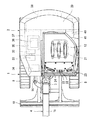
図1は、本実施形態における電動式油圧ショベルの全体構造を表す側面図であり、図2は、上面図である。なお、以降、電動式油圧ショベルが図1に示す状態にて運転者が運転席に着座した場合における運転者の前側(図1中左側)、後側(図1中右側)、左側(図1中紙面に向かって手前側)、右側(図1中紙面に向かって奥側)を、単に前側、後側、左側、右側と称する。 FIG. 1 is a side view showing the entire structure of the electric excavator in the present embodiment, and FIG. 2 is a top view. In the following, the driver's front side (left side in FIG. 1), rear side (right side in FIG. 1), left side (FIG. 1) when the driver is seated on the driver's seat in the state shown in FIG. The front side toward the middle page and the right side (back side toward the middle page in FIG. 1) are simply referred to as front side, rear side, left side, and right side.
これら図1及び図2において、電動式油圧ショベル(本実施形態では、運転質量6トン未満のミニショベル)は、クローラ式の下部走行体1と、この下部走行体1上に旋回可能に設けられた上部旋回体2と、この上部旋回体2の前側にスイングポスト3を介し連結された作業装置4とを備えている。
1 and 2, an electric hydraulic excavator (in this embodiment, a mini excavator having an operating mass of less than 6 tons) is provided on a crawler type lower traveling body 1 and on the lower traveling body 1 so as to be turnable. The
下部走行体1は、上方から見て略H字形状のトラックフレーム5を備えている。トラックフレーム5の左側後端には駆動輪6が回転可能に支持され、トラックフレーム5の左側前端には従動輪(アイドラ)7が回転可能に支持され、これら駆動輪6と従動輪7とで左の履帯(クローラ)8が掛けまわされている。そして、左の走行用油圧モータ9の駆動により、左の駆動輪6(すなわち、左の履帯8)が回転するようになっている。同様に、トラックフレーム5の右側後端には駆動輪6が回転可能に支持され、トラックフレーム5の右側前端には従動輪(アイドラ)7が回転可能に支持され、これら駆動輪6と従動輪7とで右の履帯(クローラ)8が掛けまわされている。そして、右の走行用油圧モータ9の駆動により、右の駆動輪6(すなわち、右の履帯8)が回転するようになっている。
The lower traveling body 1 includes a substantially H-
トラックフレーム5の前側には、排土用のブレード10が上下動可能に設けられている。そして、ブレード用油圧シリンダ(図示せず)の伸縮駆動により、ブレード10が上下動するようになっている。
A
上部旋回体2は、その基礎下部構造をなす旋回フレーム11と、この旋回フレーム11上の前方左側に設けられたキャノピータイプの運転室12とを備えている。下部走行体1のトラックフレーム5の中央部には旋回輪13が設けられ、この旋回輪13を介し上部旋回体2の旋回フレーム11が旋回可能に設けられている。そして、旋回用油圧モータ(図示せず)の駆動により、上部旋回体2が下部走行体1に対して旋回するようになっている。
The
スイングポスト3は、上部旋回体2の旋回フレーム11の前側に左右方向に回動可能に設けられている。そして、スイング用油圧シリンダ14の伸縮駆動により、スイングポスト3が左右方向に回動し、これによって作業装置4が左右にスイングするようになっている。
The
作業装置4は、ブーム15、アーム16、及びバケット(作業具)17を備えている。ブーム15は、スイングポスト3に上下方向に回動可能に連結されており、ブーム用油圧シリンダ18の伸縮駆動により、上下方向に回動する。アーム16は、ブーム15に上下方向に回動可能に連結されており、アーム用油圧シリンダ19の伸縮駆動により、上下方向に回動する。バケット17は、アーム16に上下方向に回動可能に連結されており、バケット用油圧シリンダ20の伸縮駆動により、上下方向に回動する。なお、バケット17は、例えばオプション用油圧アクチュエータが組み込まれたアタッチメント(図示せず)と交換可能になっている。
The working device 4 includes a
運転室12には、運転者が着座する運転席(座席)21が設けられている。運転席21の前方には、手または足で操作可能とし前後方向に操作することで左右の走行用油圧モータ9(すなわち、左右の履帯8)の動作をそれぞれ指示する左右の走行用操作レバー22が設けられている。左の走行用操作レバー22のさらに左側の足元部分には、左右方向に操作することでオプション用油圧アクチュエータ(すなわち、アタッチメント)の動作を指示するオプション用操作ペダル23が設けられている。右の走行用操作レバー22のさらに右側の足元部分には、左右方向に操作することでスイング用油圧シリンダ14(すなわち、スイングポスト3)の動作を指示するスイング用操作ペダル24が設けられている。
The driver's
運転席21の左側には、前後方向に操作することでアーム用油圧シリンダ19(すなわち、アーム16)の動作を指示し、左右方向に操作することで旋回用油圧モータ(すなわち、上部旋回体2)の動作を指示する十字操作式のアーム・旋回用操作レバー25が設けられている。運転席21の右側には、前後方向に操作することでブーム用油圧シリンダ18(すなわち、ブーム15)の動作を指示し、左右方向に操作することバケット用油圧シリンダ20(すなわち、バケット17)の動作を指示する十字操作式のブーム・バケット用操作レバー26(後述の図3参照)が設けられている。また、運転席21の右側には、前後方向に操作することでブレード用油圧シリンダ(すなわち、ブレード10)の動作を指示するブレード用操作レバー(図示せず)が設けられている。
On the left side of the driver's
また、運転席21の左側(言い換えれば、運転室12の乗降口)には、乗降阻止位置(詳細には、運転者の乗降を妨げる下降位置)と乗降許可位置(詳細には、運転者の乗降を許容する上昇位置)に操作されるゲートロックレバー27が設けられている。
In addition, on the left side of the driver's seat 21 (in other words, the entrance / exit of the driver's cab 12), a boarding / alighting prevention position (specifically, a lowering position that hinders the driver's boarding / exiting) and a boarding / alighting permission position (specifically, the driver's entrance / exit) A
また、運転席21の右側には、後述するキースイッチ28(図4参照)、ダイヤル29(図4参照)、充電スイッチ30(図4参照)、及び蓄電残量表示器31(図5参照)等が設けられている。なお、充電スイッチ30は、後述する外部電源入力部41に設けられてもよい。
In addition, on the right side of the driver's
旋回フレーム11上の運転室12の右側には、電動モータ32、油圧ポンプ33、作動油タンク34、制御装置35、及び配電盤36(後述の図4及び図12等参照)が搭載され、右外装カバー37で覆われている。また、旋回フレーム11上の運転室12の後側には、バッテリ装置38が搭載され、後外装カバー39で覆われている。なお、バッテリ装置38は、作業装置4との重量バランスをとるためのカウンタウェイトの役割も果たしている。また、運転室12の左側には左外装カバー40が取付けられ、この左外装カバー40の内側に外部電源入力部41が設けられている。
An
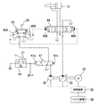
図3は、上述した電動式油圧ショベルに備えられた油圧駆動装置の構成のうち、ブーム用油圧シリンダ18に係わる構成を表す油圧回路図である。
FIG. 3 is a hydraulic circuit diagram showing a configuration related to the boom
この図3において、電動モータ32と、この電動モータ32の電力源であるバッテリ装置38と、このバッテリ装置38からの電力を電動モータ32へ供給して電動モータ32を駆動する制御装置35と、電動モータ32によって駆動される油圧ポンプ33及びパイロットポンプ42と、ブーム・バケット用操作レバー26を有する油圧パイロット式の操作装置43と、ブーム・バケット用操作レバー26の前後方向の操作に応じて油圧ポンプ33からブーム用油圧シリンダ18への圧油の流れを制御するブーム用方向切換弁44とが設けられている。
In FIG. 3, an
操作装置43は、操作レバー26と、この操作レバー26の中立位置から前側の操作量に応じてパイロットポンプ42の吐出圧を減圧してパイロット圧を生成するパイロット弁45Aと、操作レバー26の中立位置から後側の操作量に応じてパイロットポンプ42の吐出圧を減圧してパイロット圧を生成するパイロット弁45B等を有している。
The operating
そして、例えば操作レバー26を前側に操作すると、その操作量に応じてパイロット弁45Aで生成されたパイロット圧がブーム用方向切換弁44の受圧部46Aへ出力され、これによってブーム用方向切換弁44が図中右側の切換位置に切換えられる。その結果、油圧ポンプ33からの圧油がブーム用油圧シリンダ18のロッド側油室に供給されて、ブーム用油圧シリンダ18が縮短するようになっている。一方、操作レバー26を後側に操作すると、その操作量に応じてパイロット弁45Bで生成されたパイロット圧がブーム用方向切換弁44の受圧部46Bへ出力され、これによってブーム用方向切換弁44が図中左側の切換位置に切換えられる。その結果、油圧ポンプ33からの圧油がブーム用油圧シリンダ18のボトム側油室に供給されて、ブーム用油圧シリンダ18が伸張するようになっている。
Then, for example, when the
なお、図示しないが、左右の走行用油圧モータ9、アーム用油圧シリンダ19、バケット用油圧シリンダ20、旋回用油圧モータ、スイング用油圧シリンダ、及びブレード用油圧シリンダに係わる構成においては、上述したブーム用油圧シリンダ18に係わる構成とほぼ同様、操作装置及び方向切換弁等を有している。
Although not shown in the drawings, in the configuration relating to the left and right traveling
パイロットポンプ42の吐出油路にはパイロットリリーフ弁(図示せず)が接続されており、このパイロットリリーフ弁は、パイロットポンプ42の最高吐出圧を規定するようになっている。また、パイロットポンプ42の吐出油路にはロックバルブ47が設けられており、このロックバルブ47は、上述したゲートロックレバー27の操作に応じて切換えられるようになっている。
A pilot relief valve (not shown) is connected to the discharge oil passage of the
詳しく説明すると、ゲートロックレバー27にはロックスイッチ48が設けられている。そして、例えばゲートロックレバー27を乗降阻止位置(下降位置)に操作すると、ロックスイッチ48が閉接点となる。これにより、ロックスイッチ48を介しロックバルブ47のソレノイド部47aが通電されて、ロックバルブ47が図中左側の切換位置に切換えられる。この切換位置では、パイロットポンプ42からの吐出圧が操作装置に供給される。その結果、操作装置がパイロット圧を生成可能となり、全ての油圧アクチュエータが作動可能となる。一方、例えばゲートロックレバー27を乗降許可位置(上昇位置)に操作すると、ロックスイッチ48が開接点となる。これにより、ロックバルブ47のソレノイド部47aが通電されず、バネ47bの付勢力によってロックバルブ47が図中右側の中立位置となる。この中立位置では、パイロットポンプ42からの吐出圧が操作装置に供給されない。その結果、操作装置がパイロット圧を生成不能となり、全ての油圧アクチュエータが作動不能となる。
More specifically, the
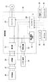
図4は、本実施形態における制御装置35の構成を関連機器とともに表すブロック図である。図5は、本実施形態におけるバッテリ装置38の構成を関連機器とともに表すブロック図である。
FIG. 4 is a block diagram showing the configuration of the
これら図4及び図5において、制御装置35は、バッテリ装置38からの電力を電動モータ32へ供給するバッテリ駆動機能(バッテリ駆動部)と、外部電源49が外部電源入力部41で接続された場合に、外部電源49から外部電源入力部41及び配電盤36を介して供給された電力をバッテリ装置38へ供給するバッテリ充電機能(バッテリ充電部)を有している。詳しく説明すると、制御装置35は、インバータ50、整流器51、昇降圧器52、補助電源回路53、及びコントローラ54を有しており、インバータ50及び昇降圧器52がバッテリ駆動部に相当し、整流器51及び昇降圧器52がバッテリ充電部に相当する。
4 and 5, the
インバータ50は、電動モータ32に配線接続されている。整流器51は、配電盤36を介し外部電源入力部41に接続されている。昇降圧器52は、インバータ50及び整流器51に接続されるとともに、バッテリ装置38に配線接続されている。コントローラ54は、インバータ50、昇降圧器52、及び補助電源回路53を制御するとともに、後述するバッテリ装置38のバッテリコントローラ55との間で通信可能としている。補助電源回路(降圧器)53は、バッテリ装置38からの電力を降圧して、コントローラ54やバッテリコントローラ55等の電子機器に供給するようになっている。
The
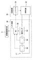
バッテリ装置38は、複数の(図5では便宜上2個のみ示す)内部バッテリ56が互いに直列接続されたバッテリ系統57と、電流センサ58と、バッテリコントローラ(BC)55とを有している。各バッテリ56は、詳細を図示しないが、例えばリチウムイオンを材料とした複数のセルからなり、それらセルを監視するセルコントローラが設けられている。各セルコントローラは、各バッテリ56の情報(詳細には、電圧及び温度等の状態量)を取得してバッテリコントローラ55に出力する。また、電流センサ58は、バッテリ系統57の電流を検出して、バッテリコントローラ55に出力するようになっている。
The
バッテリコントローラ55は、各セルコントローラから取得した各バッテリ56の電圧に基づきバッテリ系統57の総電圧を演算し、さらに電流センサ58から取得した電流に基づきバッテリ系統57の蓄電残量を演算する。そして、電流センサ58から取得した電流とともに、演算したバッテリ系統57の総電圧及び蓄電残量を、制御装置35のコントローラ54へ送信する。また、演算した蓄電残量を上述した蓄電残量表示器31に出力して、表示させるようになっている。
The
また、バッテリコントローラ55は、各セルコントローラから取得した各バッテリ56の情報に基づきバッテリ系統57に異常が生じていなかいかどうかを判断しており、異常が生じたと判断した場合にエラー信号を制御装置35のコントローラ54へ送信するようになっている。
Further, the
制御装置35のコントローラ54には、バッテリ装置38のバッテリコントローラ55からの信号以外に、上述したキースイッチ28、ダイヤル29、充電スイッチ30、及びロックスイッチ48等からの信号が入力される。キースイッチ28は、バッテリ駆動モード等を指示するものであり、キーの回転操作位置(OFF位置、ON位置、又はSTART位置)に応じて信号を出力するようになっている。ダイヤル29は、電動モータ32の目標回転数を指示するものであり、その回転操作位置に対応した目標回転数の信号を出力するようになっている。充電スイッチ30は、バッテリ充電モードを指示するものであり、その操作位置(OFF位置又はON位置)に応じて信号を出力するようになっている。
In addition to the signal from the
そして、制御装置35のコントローラ54は、上述した信号等に応じて、バッテリ装置38からの電力を電動モータ32に供給して電動モータ32を駆動するバッテリ駆動モードと、外部電源49からの電力をバッテリ装置38に供給してバッテリ系統57を充電するバッテリ充電モードとを選択的に行うようになっている。以下、各モードの詳細を説明する。
Then, the
(1)バッテリ駆動モード
制御装置35のコントローラ54は、例えば、キースイッチ28からの信号によってキースイッチ28がSTART位置に操作されたと判定し、且つ、ロックスイッチ48からの信号の有無によってゲートロックレバー27が乗降阻止位置(下降位置)にあると判定した場合に、バッテリ駆動モードを開始する。
(1) Battery drive mode The
このとき、コントローラ54は、昇降圧器52へ昇圧の指令を出力する。この指令に応じて、昇降圧器52は、バッテリ装置38からの直流電力の電圧160Vを270V程度まで昇圧する。また、コントローラ54は、ダイヤル29で指示された目標回転数の指令をインバータ50へ出力する。この指令に応じて、インバータ50は、昇降圧器52からの直流電力を交流電力に変換して、電動モータ32に供給する。すなわち、電動モータ32の実回転数が目標回転数となるように、電動モータ32の印加電圧を制御する。
At this time, the
また、コントローラ54は、例えば、バッテリコントローラ55から受信したバッテリ系統57の蓄電残量が予め設定された所定値(例えば最大蓄電量の20%)未満であるかどうかを判定しており、所定値未満である場合に、インバータ50及び昇降圧器52へ停止の指令を出力する。また、バッテリコントローラ55からエラー信号を受信した場合に(言い換えれば、バッテリ系統57に異常が生じたときに)、インバータ50及び昇降圧器52へ停止の指令を出力する。また、キースイッチ28からの信号によってキースイッチ28がOFF位置に操作されたと判定した場合に、インバータ50及び昇降圧器52へ停止の指令を出力する。この指令に応じて、インバータ50及び昇降圧器52は停止し、電動モータ32を停止させるようになっている。
For example, the
(2)バッテリ充電モード
制御装置35のコントローラ54は、例えば、キースイッチ28からの信号によってキースイッチ28がOFF位置にあると判定し、且つ、充電スイッチ30からの信号の有無によって充電スイッチ30がON位置に操作されたと判定した場合に、バッテリ充電モードを開始する。
(2) Battery Charging Mode For example, the
このとき、例えば外部電源入力部41で接続された外部電源49が三相交流200V電源49A(後述の図11参照)である場合に、整流器51は、三相交流200V電源49Aから供給された200Vの交流電力を270Vの直流電力に変換する。また、コントローラ54は、昇降圧器52へ降圧の指令を出力する。この指令に応じて、昇降圧器52は、整流器51からの直流電力の電圧270Vを160V程度まで降圧して、バッテリ装置38に供給するようになっている。
At this time, for example, when the
また、例えば外部電源入力部41で接続された外部電源49が単相交流100V電源49B(後述の図11参照)である場合に、整流器51は、単相交流100V電源49Bから供給された100Vの交流電力を90Vの直流電力に変換する。また、コントローラ54は、昇降圧器52へ昇圧の指令を出力する。この指令に応じて、昇降圧器52は、整流器51からの直流電力の電圧90Vを160V程度まで昇圧して、バッテリ装置38に供給するようになっている。
For example, when the
また、例えば外部電源入力部41で接続された外部電源49が直流200V電源49C(後述の図11参照)である場合に、コントローラ54は、昇降圧器52へ降圧の指令を出力する。この指令に応じて、昇降圧器52は、例えば直流200V電源49Cから供給された直流電力の電圧200Vを160V程度まで降圧して、バッテリ装置38に供給するようになっている。
For example, when the
また、コントローラ54は、例えば、バッテリコントローラ55から受信したバッテリ系統57の蓄電残量が最大値に達したかどうかを判定しており、最大値に達した場合に、昇降圧器52へ停止の指令を出力する。また、外部電源49からの電力供給が一定時間無い場合、若しくはバッテリコントローラ55からエラー信号を受信した場合に(言い換えれば、バッテリ系統57に異常が生じたときに)、昇降圧器52へ停止の指令を出力する。また、充電スイッチ30からの信号の有無によって充電スイッチ30がOFF位置に操作されたと判定した場合に、昇降圧器52へ停止の指令を出力する。この指令に応じて、昇降圧器52は停止して、バッテリ系統57の充電を停止させるようになっている。
For example, the
次に、外部電源入力部41について説明する。外部電源入力部41には、上述した三相交流200V電源49A、単相交流100V電源49B、及び直流200V電源49Cにそれぞれ対応した3つのコネクタ59A,59B,59Cが設けられている(後述の図6〜11参照)。すなわち、コネクタ59Aは、三相交流200V電源49Aのプラグ60Aを接続可能とし、コネクタ59Bは、単相交流100V電源49Bのプラグ60Bを接続可能とし、コネクタ59Cは、直流200V電源49Cのプラグ60Cを接続可能としている。そして、外部電源入力部41は、コネクタ59A,59B,59Cのうちの1つのコネクタを選択的に開放して外部電源と接続可能に、残りのコネクタを遮蔽して外部電源と接続不能となるように(すなわち、複数種類の外部電源が同時に接続されないように)構成されている。以下、その詳細を説明する。
Next, the external
図6は、本実施形態における外部電源入力部41の構造を表す斜視図であり、図7は、図6で示されたケース、コネクタ取付板、及びスライド板等の構造を表す断面斜視図である。図8〜10は、本実施形態における外部電源入力部41の構造を表す側面図である。
FIG. 6 is a perspective view showing the structure of the external
これら図6〜図10において、外部電源入力部41は、旋回フレーム11上に取付けられた直方体状のケース61と、このケース61に設けられたコネクタ取付板62とを有している。コネクタ取付板62には、上述したコネクタ59A,59B,59Cが前後方向(図中左右方向)に並ぶように取付けられている。また、上述した左外装カバー40の一部を構成する蓋体63は、ヒンジ64を介して上下方向に回動可能に取付けられており、外部電源入力部41を開閉可能としている。なお、ケース61には固定ブラケット65が設けられ、蓋体63には固定ブラケット65と係合可能なロック機構66が設けられている。
6 to 10, the external
ケース61の下面側には、断面L字状で前後方向に延在する一対の屈曲板67Aが取付けられており、これら屈曲板67Aの間に案内溝68Aが形成されている。同様に、ケース61の上面側には、断面L字状で前後方向に延在する一対の屈曲板67Bが取付けられており、これら屈曲板67Bの間に案内溝68Bが形成されている。スライド板69A,69Bは、それらの上下両端が案内溝68A,68Bに摺動可能に挿入されている。これにより、スライド板69A,69Bは、互いに板厚方向に重なることなく、前後方向(言い換えれば、コネクタ59A,59B,59Cの並び方向)にスライド可能に支持されている。なお、スライド板69A,69Bの前後両側には、略半円状の切欠き70が形成されている。
A pair of
そして、例えば図8で示すように、スライド板69Aを前側(図中左側)に寄せるようにスライドし、スライド板69Bを後側(図中右側)に寄せるようにスライドした場合(言い換えれば、スライド板69A,69Bを互いに離間させた場合)は、コネクタ59Aが開放され、コネクタ59C,59Bがスライド板69A,69Bで遮蔽される。これにより、三相交流200V電源49Aのプラグ60Aをコネクタ59Aに接続可能とし、単相交流100V電源49Bのプラグ60Bをコネクタ59Bに接続不能とし、直流200V電源49Cのプラグ60Cをコネクタ59Cに接続不能としている。
Then, for example, as shown in FIG. 8, when the
また、例えば図9で示すように、スライド板69A,69Bが互いに当接した状態で前側に寄せるようにスライドした場合は、コネクタ58Bが開放され、コネクタ58C,58Aがスライド板69A,69Bで遮蔽される。これにより、単相交流100V電源49Bのプラグ60Bをコネクタ59Bに接続可能とし、直流200V電源49Cのプラグ60Cをコネクタ59Cに接続不能とし、三相交流200V電源49Aのプラグ60Aをコネクタ59Aに接続不能としている。
For example, as shown in FIG. 9, when the
また、例えば図10で示すように、スライド板69A,69Bが互いに当接した状態で後側に寄せるようにスライドした場合は、コネクタ58Cが開放され、コネクタ58A,58Bがスライド板69A,69Bで遮蔽される。これにより、直流200V電源49Cのプラグ60Cをコネクタ59Cに接続可能とし、三相交流200V電源49Aのプラグ60Aをコネクタ59Aに接続不能とし、単相交流100V電源49Bのプラグ60Bをコネクタ59Bに接続不能としている。
Further, for example, as shown in FIG. 10, when the
次に、本実施形態の要部である配電盤36について説明する。図11は、本実施形態における配電盤36の構成を関連機器とともに表す電気回路図である。
Next, the
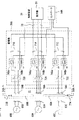
この図11において、配電盤36は、コネクタ59A,59B,59Cにそれぞれ接続された送電系統71A,71B,71Cを有している。送電系統71A,71B,71Cには、ブレーカ72A,72B,72C(過電流保護器)がそれぞれ設けられている。そして、制御装置38の小型化の観点から、送電系統71A,71B,71Cは1つの共用系統73に合流してから、制御装置35の整流器51に接続されている。そのため、例えば上述した図15で示すような従来技術の構成では、送電系統の合流部を介して外部電源が接続されていないコネクタに電流が回り込む可能性が生じる。
In FIG. 11, the
そこで、本実施形態では、コネクタ59Aと外部電源49Aのプラグ60Aとの接続を検出するために、コネクタ側接続検出用端子59Aa,59Abがコネクタ59Aに設けられ、プラグ側接続検出用端子60Aa,60Abがプラグ60Aに設けられている。また、常開接点型の開閉器(開閉リレー)74Aa,74Abが送電系統71Aに設けられ、これら開閉器74Aa,74Abを制御するリレー回路75Aが設けられている。プラグ側接続検出用端子60Aa,60Abは、互いに接続されており、コネクタ側接続検出用端子59Abは、アース電位体に接続されている。リレー回路75Aは、常開接点型の制御リレー76Aを有している。制御リレー76Aのコイルは、負極側がコネクタ側接続検出用端子59Aaに接続され、正極側が制御装置35の補助電源回路53に接続されている。また、開閉器74Aa,74Abのコイルは、負極側がアース電位体に接続され、正極側が制御リレー76Aの接点を介して補助電源回路53に接続されている。そして、例えばコネクタ59Aと外部電源49Aのプラグ60Aが接続された場合に、コネクタ側接続検出用端子59Aaとプラグ側接続検出用端子60Aaが接続され、コネクタ側接続検出用端子59Abとプラグ側接続検出用端子60Abが接続されて、制御リレー76Aのコイルの負極側がアース電位体に接続される。これにより、制御リレー76Aのコイルが通電して、制御リレー76Aの接点が開状態から閉状態に切換わり、この接点を介して開閉器74Aa,74Abのコイルが通電して、開閉器74Aa,74Abの接点が開状態から閉状態に切換わるようになっている。
Therefore, in this embodiment, in order to detect the connection between the
また、コネクタ59Bと外部電源49Bのプラグ60Bとの接続を検出するために、コネクタ側接続検出用端子59Ba,59Bbがコネクタ59Bに設けられ、プラグ側接続検出用端子60Ba,60Bbがプラグ60Bに設けられている。また、常開接点型の開閉器(開閉リレー)74Ba,74Bbが送電系統71Bに設けられ、これら開閉器74Ba,74Bbを制御するリレー回路75Bが設けられている。プラグ側接続検出用端子60Ba,60Bbは、互いに接続されており、コネクタ側接続検出用端子59Bbは、アース電位体に接続されている。リレー回路75Bは、常開接点型の制御リレー76Bを有している。制御リレー76Bのコイルは、負極側がコネクタ側接続検出用端子59Baに接続され、正極側が制御装置35の補助電源回路53に接続されている。また、開閉器74Ba,74Bbのコイルは、負極側がアース電位体に接続され、正極側が制御リレー76Bの接点を介して補助電源回路53に接続されている。そして、例えばコネクタ59Bと外部電源49Bのプラグ60Bが接続された場合に、コネクタ側接続検出用端子59Baとプラグ側接続検出用端子60Baが接続され、コネクタ側接続検出用端子59Bbとプラグ側接続検出用端子60Bbが接続されて、制御リレー76Bのコイルの負極側がアース電位体に接続される。これにより、制御リレー76Bのコイルが通電して、制御リレー76Bの接点が開状態から閉状態に切換わり、この接点を介して開閉器74Ba,74Bbのコイルが通電して、開閉器74Ba,74Bbの接点が開状態から閉状態に切換わるようになっている。
Further, in order to detect the connection between the
また、コネクタ59Cと外部電源49Cのプラグ60Cとの接続を検出するために、コネクタ側接続検出用端子59Ca,59Cbがコネクタ59Cに設けられ、プラグ側接続検出用端子60Ca,60Cbがプラグ60Cに設けられている。また、常開接点型の開閉器(開閉リレー)74Ca,74Cbが送電系統71Cに設けられ、これら開閉器74Ca,74Cbを制御するリレー回路75Cが設けられている。プラグ側接続検出用端子60Ca,60Cbは、互いに接続されており、コネクタ側接続検出用端子59Cbは、アース電位体に接続されている。リレー回路75Cは、常開接点型の制御リレー76Cを有している。制御リレー76Cのコイルは、負極側がコネクタ側接続検出用端子59Caに接続され、正極側が制御装置35の補助電源回路53に接続されている。また、開閉器74Ca,74Cbのコイルは、負極側がアース電位体に接続され、正極側が制御リレー76Cの接点を介して補助電源回路53に接続されている。そして、例えばコネクタ59Cと外部電源49Cのプラグ60Cが接続された場合に、コネクタ側接続検出用端子59Caとプラグ側接続検出用端子60Caが接続され、コネクタ側接続検出用端子59Cbとプラグ側接続検出用端子60Cbが接続されて、制御リレー76Cのコイルの負極側がアース電位体に接続される。これにより、制御リレー76Cのコイルが通電して、制御リレー76Cの接点が開状態から閉状態に切換わり、この接点を介して開閉器74Ca,74Cbのコイルが通電して、開閉器74Ca,74Cbの接点が開状態から閉状態に切換わるようになっている。
Further, in order to detect the connection between the
なお、上記において、コネクタ側接続検出用端子59Aa,59Ab,59Ba,59Bb,59Ca,59Cb及びプラグ側接続検出用端子60Aa,60Ab,60Ba,60Bb,60Ca,60Cbは、特許請求の範囲に記載の複数のコネクタのうちのいずれが外部電源のプラグと接続されたかを検出する検出部を構成する。また、リレー回路75A,75B,75Cは、複数の開閉器のうち、検出部で検出されたコネクタに対応する開閉器を閉状態に、それ以外の開閉器を開状態に制御する開閉制御部を構成する。
In the above description, the connector-side connection detection terminals 59Aa, 59Ab, 59Ba, 59Bb, 59Ca, 59Cb and the plug-side connection detection terminals 60Aa, 60Ab, 60Ba, 60Bb, 60Ca, 60Cb are plural in the claims. A detection unit that detects which one of the connectors is connected to the plug of the external power supply is configured. In addition, the
以上のような本実施形態においては、リレー回路75A,75B,75Cは、開閉器74Aa,74Ab,74Ba,74Bb,74Ca,74Cbのうち、外部電源のプラグが接続されたコネクタに対応する開閉器を閉状態に、外部電源のプラグが接続されていないコネクタに対応する開閉器を開状態に制御する。これにより、送電系統71A,71B,71Cの合流部を介して外部電源が接続されていないコネクタに電流が回り込むのを防止することができる。
In the present embodiment as described above, the
なお、上記一実施形態においては、制御リレー76A,76B,76Cのコイルの正極側が制御装置35の補助電源回路53に接続された場合を例にとって説明したが、これに限られず、本発明の趣旨及び技術思想を逸脱しない範囲内で様々な変形が可能である。すなわち、例えば補助バッテリを設け、この補助バッテリに制御リレー76A,76B,76Cのコイルの正極側が接続されてもよい。この場合も、上記同様の効果を得ることができる。
In the above embodiment, the case where the positive side of the coils of the control relays 76A, 76B, and 76C is connected to the
本発明の第2の実施形態を、図12〜図14により説明する。なお、本実施形態において、上記第1の実施形態と同等の部分は、同一の符号を付し、適宜説明を省略する。 A second embodiment of the present invention will be described with reference to FIGS. In the present embodiment, the same parts as those in the first embodiment are denoted by the same reference numerals, and description thereof will be omitted as appropriate.
図12は、本実施形態における配電盤36Aの構成を関連機器とともに表す電気回路図である。図13は、本実施形態におけるリミットスイッチの配置を外部電源入力部41の構造とともに表す側面図である。
FIG. 12 is an electric circuit diagram showing the configuration of the
本実施形態では、外部電源入力部41のケース61には、スライド板69A,69Bのスライド位置をそれぞれ検出するリミットスイッチ77A,77Bが設けられている。リミットスイッチ77Aは、スライド板69Aが所定の前側スライド位置に到達したか否かを検出し、その検出結果を検出信号として出力する。リミットスイッチ77Bは、スライド板69Bが所定の後側スライド位置に到達したか否かを検出し、その検出結果を検出信号として出力するようになっている。
In the present embodiment, the
制御装置35のコントローラ54Aは、リミットスイッチ77A,77Bから入力した検出信号に基づいて開閉器74Aa,74Ab,74Ba,74Bb,74Ca,74Cbの開閉を制御するようになっている。このようなコントローラ54Aの開閉制御の手順を図14により説明する。図14は、本実施形態におけるコントローラ54Aの開閉制御に関わる処理内容を表すフローチャートである。
The
コントローラ54Aは、ステップ80にて、バッテリ充電モードであるか否かを判定する。例えばバッテリ充電モードでない場合は、ステップ80の判定が満たされず、ステップ81に移る。ステップ81では、全ての開閉器74Aa,74Ab,74Ba,74Bb,74Ca,74Cbのコイルに制御信号を出力しないので、全ての開閉器74Aa,74Ab,74Ba,74Bb,74Ca,74Cbの接点を開状態とする。一方、例えばバッテリ充電モードである場合は、ステップ80の判定が満たされ、ステップ82に移る。
In
ステップ82では、リミットスイッチ77A,77Bからの検出信号の有無に基づき、コネクタ59A,59B,59Cのうちのいずれが外部電源のプラグと接続可能であるかを判定する。そして、ステップ83に進み、外部電源のプラグが接続可能と判定したコネクタに対応する開閉器のコイルに制御信号を出力して、その開閉器の接点を閉状態とする。また、それ以外のコネクタ、すなわち外部電源のプラグが接続不能と判定したコネクタに対応する開閉器のコイルに制御信号を出力しないので、その開閉器の接点を開状態とする。
In
具体的に説明すると、例えばリミットスイッチ77Aからの検出信号及びリミットスイッチ77Bからの検出信号がある場合は、コネクタ59Aが外部電源のプラグと接続可能で、コネクタ59B,59Cが外部電源のプラグと接続不能であると判定する(上述の図13及び図8参照)。そして、コネクタ59Aに対応する開閉器74Aa,74Abのコイルに制御信号を出力して、開閉器74Aa,74Abの接点を閉状態とする。また、コネクタ59B,59Cに対応する開閉器74Ba,74Bb,74Ca,74Cbのコイルに制御信号を出力しないので、開閉器74Ba,74Bb,74Ca,74Cbの接点を開状態とする。
More specifically, for example, when there is a detection signal from the
また、例えばリミットスイッチ77Aからの検出信号があり、リミットスイッチ77Bからの検出信号がない場合は、コネクタ59Bが外部電源のプラグと接続可能で、コネクタ59C,59Aが外部電源のプラグと接続不能であると判定する(上述の図9参照)。そして、コネクタ59Bに対応する開閉器74Ba,74Bbのコイルに制御信号を出力して、開閉器74Ba,74Bbの接点を閉状態とする。また、コネクタ59C,59Aに対応する開閉器74Ca,74Cb,74Aa,74Abのコイルに制御信号を出力しないので、開閉器74Ca,74Cb,74Aa,74Abの接点を開状態とする。
For example, when there is a detection signal from the
また、例えばリミットスイッチ77Aからの検出信号がなく、リミットスイッチ77Bからの検出信号がある場合は、コネクタ59Cが外部電源のプラグと接続可能で、コネクタ59A,59Bが外部電源のプラグと接続不能であると判定する(上述の図10参照)。そして、コネクタ59Cに対応する開閉器74Ca,74Cbのコイルに制御信号を出力して、開閉器74Ca,74Cbの接点を閉状態とする。また、コネクタ59A,59Bに対応する開閉器74Aa,74Ab,74Ba,74Bbのコイルに制御信号を出力しないので、開閉器74Aa,74Ab,74Ba,74Bbの接点を開状態とする。
For example, when there is no detection signal from the
そして、ステップ84に進み、昇降圧器52に昇圧指令又は降圧指令を出力して充電制御を行い、その後、ステップ85に進み、充電が完了したか否かを判定する。例えば充電が完了していない場合は、ステップ85の判定が満たされず、前述のステップ80に戻って上記同様の手順を繰り返す。そして、例えばステップ84の充電制御が継続されて充電が完了した場合は、ステップ85の判定が満たされ、ステップ81に移る。ステップ81では、全ての開閉器74Aa,74Ab,74Ba,74Bb,74Ca,74Cbのコイルに制御信号を出力しないので、全ての開閉器74Aa,74Ab,74Ba,74Bb,74Ca,74Cbの接点を開状態とする。
Then, the process proceeds to step 84, where a charge control is performed by outputting a step-up / step-down command to the step-up / step-
なお、上記において、リミットスイッチ76A,76Bは、特許請求の範囲に記載の複数のコネクタのうちのいずれが外部電源のプラグと接続するために選択されたかを検出する検出部を構成する。また、制御装置35のコントローラ54Aは、複数の開閉器のうち、検出部で検出されたコネクタに対応する開閉器を閉状態に、それ以外の開閉器を開状態に制御する開閉制御部を構成する。
In the above description, the
以上のような本実施形態においては、制御装置35のコントローラ54Aは、リミットスイッチ77A,77Bからの検出信号に基づき外部電源のプラグが接続可能なコネクタを判定する。そして、開閉器74Aa,74Ab,74Ba,74Bb,74Ca,74Cbのうち、外部電源のプラグが接続可能なコネクタに対応する開閉器を閉状態に、外部電源のプラグが接続不能なコネクタに対応する開閉器を開状態に制御する。これにより、上記第1の実施形態と同様、送電系統71A,71B,71Cの合流部を介して外部電源が接続されていないコネクタに電流が回り込むのを防止することができる。
In the present embodiment as described above, the
なお、上記第2の実施形態においては、制御装置35のコントローラ54Aが、上記第1の実施形態のコントローラ54の機能に加えて、リミットスイッチ77A,77Bから入力した検出信号に基づき開閉器74Aa,74Ab,74Ba,74Bb,74Ca,74Cbの開閉を制御する機能(開閉制御部)を有する場合を例にとって説明したが、これに限られず、本発明の趣旨及び技術思想を逸脱しない範囲内で様々な変形が可能である。すなわち、例えば、リミットスイッチ77A,77Bから入力した検出信号に基づき開閉器74Aa,74Ab,74Ba,74Bb,74Ca,74Cbの開閉を制御するコントローラ(開閉制御部)を、制御装置35のコントローラ54とは別体に設けてもよい。この場合も、上記同様の効果を得ることができる。
In the second embodiment, in addition to the function of the
また、上記第1及び第2の実施形態においては、バッテリ装置38からの電力を電動モータ32へ供給するバッテリ駆動機能(バッテリ駆動部)と、外部電源49からの電力をバッテリ装置38へ供給するバッテリ充電機能(バッテリ充電部)を有する制御装置35を設けた場合を例にとって説明したが、これに限られず、本発明の趣旨及び技術思想を逸脱しない範囲内で様々な変形が可能である。すなわち、バッテリ駆動部とバッテリ充電部を別体にして設けてもよい。あるいは、制御装置35は、例えば三相交流200V電源49Aが外部電源入力部41で接続された場合に、三相交流200V電源49Aからの電力を電動モータ32へ供給して電動モータ32を駆動する外部電源駆動機能(外部電源駆動部)をさらに有し、モードスイッチの操作に応じてバッテリ充電モードと外部電源駆動モードを選択的に行うようにしてもよい。そして、例えば外部電源駆動モードが選択された場合に、インバータ50は、コントローラからの目標回転数の指令に応じて、整流器51からの直流電力を交流電力に変換して、電動モータ32に供給すればよい。このような場合も、上記同様の効果を得ることができる。
In the first and second embodiments, a battery drive function (battery drive unit) that supplies power from the
また、上記第1及び第2の実施形態においては、三相交流200V電源49Aのプラグ60A、単相交流100V電源49Bのプラグ60B、及び直流200V電源49Cのプラグ60Cがそれぞれ接続可能な3つのコネクタ59A,59B,59Cを設けた場合を例にとって説明したが、これに限られず、本発明の趣旨及び技術思想を逸脱しない範囲内で様々な変形が可能である。すなわち、例えば2種類の外部電源がそれぞれ接続可能な2つのコネクタを設けてもよいし、若しくは4種類以上の外部電源がそれぞれ接続可能な4つ以上のコネクタを設けてもよい。これらの場合も、上記同様の効果を得ることができる。
Further, in the first and second embodiments, three connectors to which the
また、上記第1及び第2の実施形態においては、電動式油圧ショベルは、作業装置用油圧アクチュエータ(詳細には、ブーム用油圧シリンダ18、アーム用油圧シリンダ19、バケット用油圧シリンダ20)以外の油圧アクチュエータとして、左右の走行用油圧モータ9及び旋回用油圧モータ等を備えた場合を例にとって説明したが、これに限られない。すなわち、例えば左右の走行用油圧モータ9に代えて、バッテリ装置38からの電力によって駆動する左右の走行用電動モータを備えてもよい。また、例えば旋回用油圧モータに代えて、バッテリ装置38からの電力によって駆動する旋回用電動モータを備えてもよい。これらの場合も、上記同様の効果を得ることができる。
Further, in the first and second embodiments, the electric hydraulic excavator is other than the hydraulic actuator for the working device (specifically, the boom
また、上記第1及び第2の実施形態においては、電動式油圧ショベルは、スイング式の作業装置4を備えた場合を例にとって説明したが、これに限られず、オフセット式の作業装置を備えてもよい。また、電動式油圧ショベルは、クローラ式の下部走行体1を備えた場合を例にとって説明したが、これに限られず、ホイール式の下部走行体を備えてもよい。これらの場合も、上記同様の効果を得ることができる。 In the first and second embodiments, the electric hydraulic excavator has been described by way of an example in which the swing type work device 4 is provided. However, the present invention is not limited to this, and an offset type work device is provided. Also good. Further, although the electric hydraulic excavator has been described by taking the case where the crawler type lower traveling body 1 is provided as an example, the electric hydraulic excavator is not limited thereto, and may be provided with a wheel type lower traveling body. In these cases, the same effect as described above can be obtained.
なお、以上においては、本発明の適用対象として電動式油圧ショベルを例にとって説明したが、これに限られず、他の電動式建設機械に適用してもよいことは言うまでもない。 In the above description, the electric hydraulic excavator has been described as an application target of the present invention. However, the present invention is not limited to this, and needless to say, the present invention may be applied to other electric construction machines.
9 走行用油圧モータ
14 スイング用油圧シリンダ
18 ブーム用油圧シリンダ
19 アーム用油圧シリンダ
20 バケット用油圧シリンダ
32 電動モータ
33 油圧ポンプ
35 制御装置
36,36A 配電盤
38 バッテリ装置
41 外部電源入力部
49 外部電源
49A 三相交流200V電源(外部電源)
49B 単相交流100V電源(外部電源)
49C 直流200V電源(外部電源)
50 インバータ
51 整流器
52 昇降圧器
53 補助電源回路
54,54A コントローラ
55 バッテリコントローラ
56 内部バッテリ
57 バッテリ系統
59A,59B,59C コネクタ
59Aa,59Ab コネクタ側接続検出用端子
59Ba,59Bb コネクタ側接続検出用端子
59Ca,59Cb コネクタ側接続検出用端子
60A,60B,60C プラグ
60Aa,60Ab プラグ側接続検出用端子
60Ba,60Bb プラグ側接続検出用端子
60Ca,60Cb プラグ側接続検出用端子
69A,69B スライド板
71A,71B,71C 送電系統
73 共用系統
74Aa,74Ab 開閉器
74Ba,74Bb 開閉器
74Ca,74Cb 開閉器
75A,75B,75C リレー回路
76A,76B,76C 制御リレー
77A,77B リミットスイッチ
DESCRIPTION OF
49B Single-phase AC 100V power supply (external power supply)
49C DC 200V power supply (external power supply)
50
Claims (3)
前記電動モータによって駆動される油圧ポンプと、
前記油圧ポンプから吐出された圧油により駆動される油圧アクチュエータと、
前記電動モータの電力源である内部バッテリと、
複数種類の外部電源のプラグがそれぞれ接続可能な複数のコネクタと、
前記複数のコネクタにそれぞれ接続された複数の送電系統と、
前記複数の送電系統が1つの共用系統を介して接続されたバッテリ充電部とを備え、
前記バッテリ充電部は、前記複数のコネクタのうちのいずれかが前記外部電源のプラグと接続された場合に、前記外部電源から供給された電力を前記内部バッテリに供給する電動式建設機械において、
前記複数の送電系統にそれぞれ設けられ、前記複数のコネクタにそれぞれ対応した複数の開閉器と、
前記複数のコネクタのうちのいずれが前記外部電源のプラグと接続されたか、若しくは前記複数のコネクタのうちのいずれが前記外部電源のプラグと接続するために選択されたかを検出する検出部と、
前記複数の開閉器のうち、前記検出部で検出されたコネクタに対応する開閉器を閉状態に、それ以外の開閉器を開状態に制御する開閉制御部とを備えたことを特徴とする電動式建設機械。 An electric motor;
A hydraulic pump driven by the electric motor;
A hydraulic actuator driven by pressure oil discharged from the hydraulic pump;
An internal battery that is a power source of the electric motor;
Multiple connectors to which multiple types of external power plugs can be connected, and
A plurality of power transmission systems respectively connected to the plurality of connectors;
A plurality of power transmission systems including a battery charging unit connected via one shared system;
In the electric construction machine that supplies power supplied from the external power source to the internal battery when any of the plurality of connectors is connected to the plug of the external power source, the battery charging unit,
A plurality of switches respectively provided in the plurality of power transmission systems, corresponding to the plurality of connectors, and
A detection unit for detecting which one of the plurality of connectors is connected to the plug of the external power supply or which one of the plurality of connectors is selected to connect to the plug of the external power supply;
An electric motor comprising: an opening / closing control unit for controlling a switch corresponding to the connector detected by the detection unit among the plurality of switches to a closed state and other switches to an open state. Construction machine.
前記検出部は、前記複数のコネクタにそれぞれ設けられ、前記外部電源のプラグに設けられたプラグ側接続検出用端子と接続されるコネクタ側接続検出用端子を有し、
前記開閉制御部は、前記コネクタと前記開閉器の組合せに対応した制御リレーをそれぞれ有する複数のリレー回路であり、
前記複数のリレー回路は、前記複数のコネクタのうちのいずれかと前記外部電源のプラグが接続された場合に、対応する前記コネクタ側接続検出用端子と前記プラグ側接続検出用端子の接続によって対応する前記制御リレーのコイルが通電して、対応する前記制御リレーの接点が閉状態に切換わり、この接点を介して対応する前記開閉器のコイルが通電して、対応する前記開閉器の接点が閉状態に切換わるように構成されたことを特徴とする電動式建設機械。 The electric construction machine according to claim 1,
The detection unit is provided on each of the plurality of connectors, and has a connector-side connection detection terminal connected to a plug-side connection detection terminal provided on a plug of the external power source,
The switching control unit is a plurality of relay circuits each having a control relay corresponding to the combination of the connector and the switch,
The plurality of relay circuits correspond by connecting the corresponding connector-side connection detection terminal and the plug-side connection detection terminal when any one of the plurality of connectors and the plug of the external power supply are connected. When the coil of the control relay is energized, the corresponding contact of the control relay is switched to the closed state, and the corresponding coil of the switch is energized via this contact, and the contact of the corresponding switch is closed. An electric construction machine configured to switch to a state.
前記複数のコネクタのうちのいずれかを前記外部電源のプラグと接続可能なように選択的に開放しつつ、残りのコネクタを前記外部電源のプラグと接続不能なように遮蔽するスライド板を設けており、
前記検出部は、前記スライド板のスライド位置を検出するリミットスイッチを有し、
前記開閉制御部は、前記複数の開閉器のうち、前記リミットスイッチの検出結果に基づき前記外部電源のプラグが接続可能と判定したコネクタに対応する開閉器を閉状態に、それ以外の開閉器を開状態に制御するコントローラであることを特徴とする電動式建設機械。 The electric construction machine according to claim 1,
Provided with a slide plate that selectively opens one of the plurality of connectors so as to be connectable to the plug of the external power supply, and shields the remaining connectors so that they cannot be connected to the plug of the external power supply. And
The detection unit has a limit switch for detecting a slide position of the slide plate,
The switching control unit closes a switch corresponding to a connector that is determined to be connectable to the plug of the external power source based on a detection result of the limit switch, and switches the other switches. An electric construction machine characterized by being a controller that controls to an open state.
Priority Applications (7)
| Application Number | Priority Date | Filing Date | Title |
|---|---|---|---|
| JP2012182534A JP5837863B2 (en) | 2012-08-21 | 2012-08-21 | Electric construction machine |
| CN201610907391.4A CN106284452B (en) | 2012-08-21 | 2013-06-19 | Electric construction machine |
| PCT/JP2013/066831 WO2014030415A1 (en) | 2012-08-21 | 2013-06-19 | Electric construction machine |
| CN201380044080.4A CN104583497B (en) | 2012-08-21 | 2013-06-19 | Electric construction machine |
| EP13831047.9A EP2889432B1 (en) | 2012-08-21 | 2013-06-19 | Electric construction machine |
| KR1020157004367A KR101711766B1 (en) | 2012-08-21 | 2013-06-19 | Electric construction machine |
| US14/422,196 US9889750B2 (en) | 2012-08-21 | 2013-06-19 | Electric construction machine |
Applications Claiming Priority (1)
| Application Number | Priority Date | Filing Date | Title |
|---|---|---|---|
| JP2012182534A JP5837863B2 (en) | 2012-08-21 | 2012-08-21 | Electric construction machine |
Publications (2)
| Publication Number | Publication Date |
|---|---|
| JP2014040718A true JP2014040718A (en) | 2014-03-06 |
| JP5837863B2 JP5837863B2 (en) | 2015-12-24 |
Family
ID=50149733
Family Applications (1)
| Application Number | Title | Priority Date | Filing Date |
|---|---|---|---|
| JP2012182534A Active JP5837863B2 (en) | 2012-08-21 | 2012-08-21 | Electric construction machine |
Country Status (6)
| Country | Link |
|---|---|
| US (1) | US9889750B2 (en) |
| EP (1) | EP2889432B1 (en) |
| JP (1) | JP5837863B2 (en) |
| KR (1) | KR101711766B1 (en) |
| CN (2) | CN106284452B (en) |
| WO (1) | WO2014030415A1 (en) |
Cited By (1)
| Publication number | Priority date | Publication date | Assignee | Title |
|---|---|---|---|---|
| JP2023149027A (en) * | 2022-03-30 | 2023-10-13 | 住友建機株式会社 | excavator |
Families Citing this family (26)
| Publication number | Priority date | Publication date | Assignee | Title |
|---|---|---|---|---|
| JP5692539B2 (en) * | 2012-09-18 | 2015-04-01 | 株式会社豊田自動織機 | Industrial vehicle |
| US9484602B1 (en) * | 2013-08-22 | 2016-11-01 | OSC Manufacturing & Equipment Services, Inc. | Light tower having a battery housing |
| US10131042B2 (en) | 2013-10-21 | 2018-11-20 | Milwaukee Electric Tool Corporation | Adapter for power tool devices |
| JP6401241B2 (en) * | 2014-03-06 | 2018-10-10 | 住友建機株式会社 | Excavator |
| JP6596458B2 (en) * | 2017-03-13 | 2019-10-23 | 株式会社日立建機ティエラ | Hydraulic drive device for electric hydraulic work machine |
| JP2019190104A (en) * | 2018-04-24 | 2019-10-31 | ヤンマー株式会社 | Electric driven work machine |
| JP7053360B2 (en) * | 2018-04-24 | 2022-04-12 | ヤンマーパワーテクノロジー株式会社 | Electric work machine |
| KR102027230B1 (en) * | 2018-06-27 | 2019-10-02 | 대모 엔지니어링 주식회사 | Charging system for electrnic hydraulic breaker |
| JP6944426B2 (en) * | 2018-09-05 | 2021-10-06 | 株式会社日立建機ティエラ | Electric construction machinery |
| JP7175145B2 (en) * | 2018-09-14 | 2022-11-18 | 株式会社小松製作所 | electric construction machine |
| JP7204401B2 (en) * | 2018-09-28 | 2023-01-16 | 株式会社小松製作所 | electric construction machine |
| JP7360581B2 (en) * | 2019-04-04 | 2023-10-13 | コベルコ建機株式会社 | Operating mechanism for working machines and working machines equipped with the same |
| KR102702058B1 (en) * | 2019-09-10 | 2024-09-02 | 에이치디현대인프라코어 주식회사 | Apparatus for supplying power for electricity construction heavy equipments |
| FR3113262B1 (en) * | 2020-08-08 | 2023-03-10 | Baptiste Hanser | Electrified construction machine supporting an auxiliary energy element. |
| US11890953B2 (en) * | 2021-03-29 | 2024-02-06 | Deere & Company | Electric accessory interface for work vehicle |
| JPWO2022210391A1 (en) * | 2021-03-31 | 2022-10-06 | ||
| CN117120692A (en) * | 2021-03-31 | 2023-11-24 | 住友建机株式会社 | Excavator |
| US12587226B2 (en) * | 2021-06-10 | 2026-03-24 | Rosemount Inc. | Wireless discrete input/output with external power option |
| JP7519983B2 (en) * | 2021-12-24 | 2024-07-22 | 株式会社クボタ | Electric work vehicle |
| JP7733812B2 (en) * | 2022-03-31 | 2025-09-03 | 株式会社日立建機ティエラ | Electric powered work machinery |
| JP7846032B2 (en) * | 2023-02-27 | 2026-04-14 | 株式会社竹内製作所 | Work vehicles |
| US12425062B2 (en) | 2023-03-06 | 2025-09-23 | Rosemount Inc. | Load adapter module for wireless discrete input/output field device |
| DE102023202728A1 (en) * | 2023-03-27 | 2024-10-02 | Scheuerle Fahrzeugfabrik Gmbh | power supply unit, system and heavy-duty modular vehicle |
| JP2025142999A (en) * | 2024-03-18 | 2025-10-01 | ヤンマーホールディングス株式会社 | Work machinery |
| EP4631771A1 (en) * | 2024-04-12 | 2025-10-15 | Wimmer Felstechnik Gesellschaft m.b.H. | Excavator system, in particular tunnel excavator system |
| CN118621862A (en) * | 2024-06-21 | 2024-09-10 | 徐州徐工挖掘机械有限公司 | A relay control system and method |
Citations (2)
| Publication number | Priority date | Publication date | Assignee | Title |
|---|---|---|---|---|
| JP2011015548A (en) * | 2009-07-02 | 2011-01-20 | Toyota Motor Corp | Electric vehicle |
| JP2012001889A (en) * | 2010-06-14 | 2012-01-05 | Hitachi Constr Mach Co Ltd | Electric construction machine |
Family Cites Families (14)
| Publication number | Priority date | Publication date | Assignee | Title |
|---|---|---|---|---|
| JP4961321B2 (en) * | 2007-10-18 | 2012-06-27 | 鹿島道路株式会社 | Construction method using battery-powered construction machine |
| US7827787B2 (en) * | 2007-12-27 | 2010-11-09 | Deere & Company | Hydraulic system |
| JP5004834B2 (en) * | 2008-03-13 | 2012-08-22 | 日立建機株式会社 | Work machine |
| JP2009278706A (en) * | 2008-05-12 | 2009-11-26 | Toyota Motor Corp | Charging apparatus for electric vehicle |
| JP5319236B2 (en) * | 2008-10-22 | 2013-10-16 | 日立建機株式会社 | Power supply and work machine |
| JP5185082B2 (en) * | 2008-11-18 | 2013-04-17 | 日立建機株式会社 | Electric hydraulic work machine |
| US8513837B2 (en) * | 2009-07-28 | 2013-08-20 | Parker-Hannifin Corporation | Electrical interrupt system and method for use in a hybrid system |
| CN102021921B (en) * | 2009-09-18 | 2012-05-23 | 鞍钢集团矿业公司 | Power supply equipment and power supply method for underground dual-energy scraper |
| JP5527883B2 (en) * | 2009-12-08 | 2014-06-25 | 住友建機株式会社 | Construction machinery |
| JP2011122364A (en) * | 2009-12-11 | 2011-06-23 | Fuji Heavy Ind Ltd | Work vehicle |
| EP2520456B1 (en) * | 2009-12-28 | 2019-02-27 | Toyota Jidosha Kabushiki Kaisha | Vehicle |
| US20110198141A1 (en) * | 2010-02-16 | 2011-08-18 | Genie Industries, Inc. | Hydraulic electric hybrid drivetrain |
| JP5384397B2 (en) * | 2010-02-19 | 2014-01-08 | 日立建機株式会社 | Electric construction machine |
| JP5884699B2 (en) * | 2012-09-28 | 2016-03-15 | 三菱自動車工業株式会社 | Charging connector housing device for truck electric vehicle |
-
2012
- 2012-08-21 JP JP2012182534A patent/JP5837863B2/en active Active
-
2013
- 2013-06-19 CN CN201610907391.4A patent/CN106284452B/en not_active Expired - Fee Related
- 2013-06-19 US US14/422,196 patent/US9889750B2/en active Active
- 2013-06-19 WO PCT/JP2013/066831 patent/WO2014030415A1/en not_active Ceased
- 2013-06-19 CN CN201380044080.4A patent/CN104583497B/en active Active
- 2013-06-19 EP EP13831047.9A patent/EP2889432B1/en active Active
- 2013-06-19 KR KR1020157004367A patent/KR101711766B1/en not_active Expired - Fee Related
Patent Citations (2)
| Publication number | Priority date | Publication date | Assignee | Title |
|---|---|---|---|---|
| JP2011015548A (en) * | 2009-07-02 | 2011-01-20 | Toyota Motor Corp | Electric vehicle |
| JP2012001889A (en) * | 2010-06-14 | 2012-01-05 | Hitachi Constr Mach Co Ltd | Electric construction machine |
Cited By (1)
| Publication number | Priority date | Publication date | Assignee | Title |
|---|---|---|---|---|
| JP2023149027A (en) * | 2022-03-30 | 2023-10-13 | 住友建機株式会社 | excavator |
Also Published As
| Publication number | Publication date |
|---|---|
| US20150231974A1 (en) | 2015-08-20 |
| WO2014030415A1 (en) | 2014-02-27 |
| CN104583497A (en) | 2015-04-29 |
| US9889750B2 (en) | 2018-02-13 |
| EP2889432A1 (en) | 2015-07-01 |
| KR101711766B1 (en) | 2017-03-03 |
| JP5837863B2 (en) | 2015-12-24 |
| EP2889432A4 (en) | 2016-03-30 |
| EP2889432B1 (en) | 2018-01-03 |
| CN104583497B (en) | 2017-02-22 |
| CN106284452B (en) | 2018-10-23 |
| KR20150038169A (en) | 2015-04-08 |
| CN106284452A (en) | 2017-01-04 |
Similar Documents
| Publication | Publication Date | Title |
|---|---|---|
| JP5837863B2 (en) | Electric construction machine | |
| JP6038934B2 (en) | Construction machinery | |
| CN103718424B (en) | Electric construction machine | |
| JP5778752B2 (en) | Electric construction machine | |
| JP6944426B2 (en) | Electric construction machinery | |
| EP2700755B1 (en) | Electromotive drive device of construction machine | |
| US8700246B2 (en) | Electrically-operated construction machine | |
| KR101848947B1 (en) | Hybrid construction machine | |
| JP2013129976A (en) | Electric construction machine | |
| JP2020051065A (en) | Electric construction machine | |
| US20250250769A1 (en) | Work machine | |
| JP2023125756A (en) | Electric excavators and excavator series | |
| JP2025142999A (en) | Work machinery | |
| JP2023134163A (en) | electric excavator |
Legal Events
| Date | Code | Title | Description |
|---|---|---|---|
| A621 | Written request for application examination |
Free format text: JAPANESE INTERMEDIATE CODE: A621 Effective date: 20140815 |
|
| RD02 | Notification of acceptance of power of attorney |
Free format text: JAPANESE INTERMEDIATE CODE: A7422 Effective date: 20140815 |
|
| A131 | Notification of reasons for refusal |
Free format text: JAPANESE INTERMEDIATE CODE: A131 Effective date: 20150623 |
|
| A521 | Request for written amendment filed |
Free format text: JAPANESE INTERMEDIATE CODE: A523 Effective date: 20150805 |
|
| TRDD | Decision of grant or rejection written | ||
| A01 | Written decision to grant a patent or to grant a registration (utility model) |
Free format text: JAPANESE INTERMEDIATE CODE: A01 Effective date: 20151027 |
|
| A61 | First payment of annual fees (during grant procedure) |
Free format text: JAPANESE INTERMEDIATE CODE: A61 Effective date: 20151106 |
|
| R150 | Certificate of patent or registration of utility model |
Ref document number: 5837863 Country of ref document: JP Free format text: JAPANESE INTERMEDIATE CODE: R150 |
|
| S111 | Request for change of ownership or part of ownership |
Free format text: JAPANESE INTERMEDIATE CODE: R313113 |
|
| S531 | Written request for registration of change of domicile |
Free format text: JAPANESE INTERMEDIATE CODE: R313531 |
|
| R350 | Written notification of registration of transfer |
Free format text: JAPANESE INTERMEDIATE CODE: R350 |