JP2014040748A - Road sweeper - Google Patents

Road sweeper Download PDF

Info

Publication number
JP2014040748A
JP2014040748A JP2012184373A JP2012184373A JP2014040748A JP 2014040748 A JP2014040748 A JP 2014040748A JP 2012184373 A JP2012184373 A JP 2012184373A JP 2012184373 A JP2012184373 A JP 2012184373A JP 2014040748 A JP2014040748 A JP 2014040748A
Authority
JP
Japan
Prior art keywords
liquid
air
passage
injection
main body
Prior art date
Legal status (The legal status is an assumption and is not a legal conclusion. Google has not performed a legal analysis and makes no representation as to the accuracy of the status listed.)
Granted
Application number
JP2012184373A
Other languages
Japanese (ja)
Other versions
JP6018838B2 (en
Inventor
Kimiyasu Kato
公康 加藤
Shiyuuji Sawai
秋司 沢井
Noboru Suwa
昇 諏訪
Current Assignee (The listed assignees may be inaccurate. Google has not performed a legal analysis and makes no representation or warranty as to the accuracy of the list.)
Kato Works Co Ltd
Kato Seisakusho Co Ltd
Original Assignee
Kato Works Co Ltd
Kato Seisakusho Co Ltd
Priority date (The priority date is an assumption and is not a legal conclusion. Google has not performed a legal analysis and makes no representation as to the accuracy of the date listed.)
Filing date
Publication date
Application filed by Kato Works Co Ltd, Kato Seisakusho Co Ltd filed Critical Kato Works Co Ltd
Priority to JP2012184373A priority Critical patent/JP6018838B2/en
Publication of JP2014040748A publication Critical patent/JP2014040748A/en
Application granted granted Critical
Publication of JP6018838B2 publication Critical patent/JP6018838B2/en
Active legal-status Critical Current
Anticipated expiration legal-status Critical

Links

Images

Landscapes

  • Cleaning Of Streets, Tracks, Or Beaches (AREA)

Abstract

【課題】高出力のポンプを用いることなく、気泡が発生した液体を路面に噴射可能な路面清掃車を提供すること。
【解決手段】路面清掃車の噴射ユニットの噴射本体部は、送液方向側の端に位置する噴射口に向かって液体が送液される送液通路であって、通路軸に垂直な断面積が前記送液通路の他の部分に比べて部分的に小さくなる断面積減少部を備える送液通路と、前記送液通路の前記断面積減少部に向かって空気を送気することにより、前記液体に前記気泡を発生させる送気通路と、を備える。前記噴射ユニットは、ケーシングの外部から前記空気を前記送気通路に導入する空気導入部を備える。
【選択図】図5
The present invention provides a road cleaning vehicle capable of injecting liquid in which bubbles are generated onto a road surface without using a high-output pump.
An injection main body portion of an injection unit of a road surface cleaning vehicle is a liquid supply passage through which liquid is supplied toward an injection port located at an end on the liquid supply direction side, and has a cross-sectional area perpendicular to the passage axis. By supplying air toward the cross-sectional area reducing portion of the liquid-feeding passage, and a liquid-feeding passage having a cross-sectional area reducing portion that is partially smaller than the other parts of the liquid-feeding passage, An air supply passage for generating the bubbles in the liquid. The said injection unit is provided with the air introduction part which introduces the said air into the said air supply path from the exterior of a casing.
[Selection] Figure 5

Description

本発明は、噴射ユニットによって液体を路面に噴射することにより、路面の隙間に入込んだ目詰まり物を浮き上がらせ、吸引ユニットによって浮き上がった目詰まり物を吸引する路面清掃車に関する。   The present invention relates to a road surface cleaning vehicle that injects liquid onto a road surface by an injection unit to lift the clogged material that has entered a gap in the road surface and sucks the clogged material that has been lifted by a suction unit.

特許文献1には、路面の隙間に入込んだ土砂、粉塵等の目詰まり物を吸引ユニットによって、吸引口から吸引する路面清掃車が開示されている。この路面清掃車には、噴射口から路面に向かって液体を噴射する噴射ユニットが、設けられている。噴射ユニットは、通路軸に沿って送液通路が形成された噴射本体部を備える。送液通路の送液方向側の端に、噴射口が位置している。また、送液通路には、通路軸に垂直な断面積が送液通路の他の部分に比べて部分的に小さくなる断面積減少部が、設けられている。   Patent Document 1 discloses a road cleaning vehicle that sucks clogged materials such as earth and sand and dust that have entered a gap between road surfaces from a suction port by a suction unit. The road cleaning vehicle is provided with an injection unit that injects liquid from the injection port toward the road surface. The injection unit includes an injection main body portion in which a liquid supply passage is formed along a passage axis. An injection port is located at the end of the liquid supply passage on the liquid supply direction side. In addition, the liquid feed passage is provided with a cross-sectional area reduction portion in which the cross-sectional area perpendicular to the passage axis is partially smaller than the other parts of the liquid feed passage.

この路面清掃車では、高出力のポンプ等によって高圧にされた液体が、送液通路に導入される。高圧液体が送液通路に導入されることにより、断面積減少部で液体の流速が急激に大きくなり、断面積減少部で液体の圧力が急激に低下する。これにより、断面積減少部で、液体に気泡が発生する。そして、気泡が発生した液体が、噴射口から路面に噴射される。液体に含まれる気泡は、路面又は路面の近傍で、崩壊する。気泡が崩壊する際に生じるマイクロジェット、衝撃波等のエネルギーによって、路面の隙間に入込んだ目詰まり物を浮き上がらせる。そして、浮き上がった目詰まり物を、吸引ユニットによって吸引する。   In this road cleaning vehicle, the liquid that has been made high pressure by a high-power pump or the like is introduced into the liquid supply passage. When the high-pressure liquid is introduced into the liquid feeding passage, the flow velocity of the liquid rapidly increases at the cross-sectional area decreasing portion, and the liquid pressure is rapidly decreased at the cross-sectional area decreasing portion. Thereby, bubbles are generated in the liquid at the cross-sectional area decreasing portion. Then, the liquid in which bubbles are generated is ejected from the ejection port onto the road surface. Bubbles contained in the liquid collapse on or near the road surface. The clogged material that has entered the gaps on the road surface is lifted by the energy of micro jets, shock waves, etc. generated when the bubbles collapse. Then, the clogged material that floats is sucked by the suction unit.

特開2003−74032号公報JP 2003-74032 A

前記特許文献1の路面清掃車では、断面積減少部で液体に気泡を発生させるために、高圧の液体を送液通路に導入する必要がある。高圧液体を生成するためには、高出力のポンプが必要となり、高出力のポンプは、大型で、重量が大きい。高出力のポンプを設けることにより、路面清掃車も、大型化し、重量が大きくなる。また、大型で、重量が大きい高出力のポンプを設けることにより、路面清掃車において、吸引した目詰まり物の積載量が少なくなる。さらに、高出力のポンプを設けることにより、ポンプからの騒音も大きくなる。   In the road cleaning vehicle of Patent Document 1, it is necessary to introduce a high-pressure liquid into the liquid feeding passage in order to generate bubbles in the liquid at the cross-sectional area reducing portion. In order to produce the high-pressure liquid, a high-power pump is required, and the high-power pump is large and heavy. By providing a high-output pump, the road cleaning vehicle is also increased in size and weight. In addition, by providing a high-power pump that is large and heavy, the load of suctioned clogged items is reduced in the road sweeper. Furthermore, by providing a high-output pump, noise from the pump also increases.

本発明は前記課題に着目してなされたものであり、その目的とするところは、高出力のポンプを用いることなく、気泡が発生した液体を路面に噴射可能な路面清掃車を提供することにある。   The present invention has been made paying attention to the above-mentioned problems, and an object of the present invention is to provide a road cleaning vehicle capable of injecting a liquid in which bubbles are generated on a road surface without using a high-output pump. is there.

前記目的を達成するために、本発明のある態様の路面清掃車は、路面に向かって開口する開口部が形成されるケーシングと、前記ケーシングの内部に位置する吸引口から吸引通路を通して吸引を行う吸引ユニットと、前記ケーシングの前記内部に設けられる噴射本体部を備え、前記ケーシングの前記内部に位置する噴射口から気泡が発生した液体を前記路面に向かって噴射する噴射ユニットと、を備え、前記噴射ユニットの前記噴射本体部は、 通路軸に沿って延設され、送液方向側の端に位置する前記噴射口に向かって前記液体が送液される送液通路であって、前記通路軸に垂直な断面積が前記送液通路の他の部分に比べて部分的に小さくなる断面積減少部を備える送液通路と、前記断面積減少部で前記送液通路に連通し、前記送液通路の前記断面積減少部に向かって空気を送気することにより、前記液体に前記気泡を発生させる送気通路と、を備え、前記噴射ユニットは、前記送液通路に前記液体を導入する液体導入部と、前記ケーシングの外部から前記空気を前記送気通路に導入する空気導入部と、を備える。   In order to achieve the above object, a road cleaning vehicle according to an aspect of the present invention performs suction through a suction passage from a casing in which an opening that opens toward the road surface is formed, and a suction port located inside the casing. A suction unit; and an injection body that is provided inside the casing, and includes an injection unit that injects a liquid in which bubbles are generated from an injection port located inside the casing toward the road surface, The injection main body portion of the injection unit is a liquid supply passage that extends along the passage axis, and that feeds the liquid toward the injection port located at the end on the liquid supply direction side. A liquid-feeding passage having a cross-sectional area reducing portion whose cross-sectional area perpendicular to the other part of the liquid-feeding passage is partially smaller than that of the liquid-feeding passage; Aisle An air supply passage for generating air bubbles in the liquid by supplying air toward the cross-sectional area reducing portion, and the ejection unit introduces the liquid into the liquid supply passage. And an air introduction part for introducing the air into the air supply passage from the outside of the casing.

本発明によれば、高出力のポンプを用いることなく、気泡が発生した液体を路面に噴射可能な路面清掃車を提供することができる。   ADVANTAGE OF THE INVENTION According to this invention, the road cleaning vehicle which can inject the liquid which the bubble generate | occur | produced on the road surface can be provided, without using a high output pump.

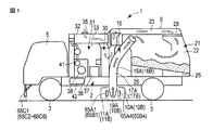
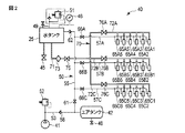
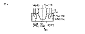
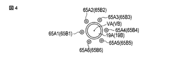
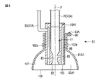
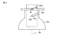
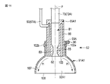
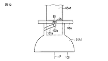
本発明の第1の実施形態に係る路面清掃車の構成を示す概略図。1 is a schematic view showing the configuration of a road sweeper according to a first embodiment of the present invention. 第1の実施形態に係る噴射ユニットの構成を示す概略図。Schematic which shows the structure of the injection unit which concerns on 1st Embodiment. 第1の実施形態に係るある1つのケーシングの内部構成を概略的に示す断面図。Sectional drawing which shows schematically the internal structure of one certain casing which concerns on 1st Embodiment. 図3を矢印U1の方向から視た概略図。The schematic diagram which looked at Drawing 3 from the direction of arrow U1. 第1の実施形態に係るケーシングの内部に設けられるある1つの噴射本体部の構成を概略的に示す断面図。Sectional drawing which shows schematically the structure of one injection main-body part provided in the inside of the casing which concerns on 1st Embodiment. 第2の実施形態に係るある1つのケーシングの内部構成を概略的に示す断面図。Sectional drawing which shows schematically the internal structure of one casing which concerns on 2nd Embodiment. 図6を矢印U2の方向から視た概略図。FIG. 7 is a schematic view of FIG. 6 viewed from the direction of arrow U2. 第2の実施形態に係るある1つのケーシングの内部に設けられる駆動リングの構成を概略的に示す斜視図。The perspective view which shows schematically the structure of the drive ring provided in the inside of a certain casing which concerns on 2nd Embodiment. 第2の実施形態に係るケーシングの内部に設けられるある1つの噴射本体部及びある1つの拡散筒状部の構成を、拡散筒状部が非拡散位置に位置する状態で概略的に示す断面図。Sectional drawing which shows schematically the structure of one injection main body part and one diffusion cylinder part provided in the inside of the casing which concerns on 2nd Embodiment in the state in which a diffusion cylinder part is located in a non-diffusion position. . 図9を矢印S1の方向から視た概略図。FIG. 10 is a schematic view of FIG. 9 viewed from the direction of arrow S1. 第2の実施形態に係るケーシングの内部に設けられるある1つの噴射本体部及びある1つの拡散筒状部の構成を、拡散筒状部が拡散位置に位置する状態で概略的に示す断面図。Sectional drawing which shows schematically the structure of a certain injection main body part provided in the inside of the casing which concerns on 2nd Embodiment, and a certain one diffusion cylinder part in the state in which a diffusion cylinder part is located in a diffusion position. 図11を矢印S2の方向から視た概略図。FIG. 11 is a schematic view of FIG. 11 viewed from the direction of arrow S2. 第3の実施形態に係るケーシングの内部に設けられるある1つの噴射本体部及びある1つの拡散筒状部の構成を概略的に示す斜視図。The perspective view which shows roughly the structure of a certain injection main body part provided in the inside of the casing which concerns on 3rd Embodiment, and a certain one diffusion cylinder part. 第3の実施形態に係るケーシングの内部に設けられるある1つの噴射本体部及びある1つの拡散筒状部の構成を概略的に示す断面図。Sectional drawing which shows schematically the structure of a certain injection main body part provided in the inside of the casing which concerns on 3rd Embodiment, and a certain one diffusion cylinder part.

(第1の実施形態)
本発明の第1の実施形態について図1乃至図5を参照して説明する。図1は、本実施形態の路面清掃車1の構成を示す図である。図1に示すように、路面清掃車1は、車体2と、車体2に取付けられる車輪3と、を備える。また、車体2の前方方向側の部位には、運転室5が設けられている。また、運転室5の後方方向側には、外装カバー(ホッパー兼機関室カバー)6が設けられている。外装カバー6は、車体2に取付けられている。
(First embodiment)
A first embodiment of the present invention will be described with reference to FIGS. FIG. 1 is a diagram illustrating a configuration of a road cleaning vehicle 1 according to the present embodiment. As shown in FIG. 1, the road cleaning vehicle 1 includes a vehicle body 2 and wheels 3 attached to the vehicle body 2. A driver's cab 5 is provided at the front side of the vehicle body 2. An exterior cover (a hopper and engine room cover) 6 is provided on the rear side of the cab 5. The exterior cover 6 is attached to the vehicle body 2.

また、車体2には、ケーシング10A,10Bが取付けられている。ケーシング10A,10Bは、車体2より鉛直下方向側に位置している。ケーシング10Aが左側方方向側の部位に位置し、ケーシング10Bが右側方方向側の部位に位置している。それぞれのケーシング10A,10Bには、路面に向かって開口する開口部11A,11Bが形成されている。   Further, casings 10 </ b> A and 10 </ b> B are attached to the vehicle body 2. The casings 10 </ b> A and 10 </ b> B are positioned vertically downward from the vehicle body 2. The casing 10A is located at the left side portion, and the casing 10B is located at the right side portion. Openings 11A and 11B that open toward the road surface are formed in the respective casings 10A and 10B.

路面清掃車1には、路面の隙間に入込んだ土砂、粉塵等の目詰まり物を吸引する吸引ユニット15が、設けられている。吸引ユニット15は、車体2に取付けられる吸引ホース16A,16Bを備える。それぞれの吸引ホース16A,16Bの内部には、吸引通路17A,17Bが延設されている。それぞれの吸引通路17A,17Bの一端には、吸引口19A,19Bが形成されている。吸引口19Aはケーシング10Aの内部に位置し、吸引口19Bはケーシング10Bの内部に位置している。   The road surface cleaning vehicle 1 is provided with a suction unit 15 that sucks clogged materials such as earth and sand and dust that have entered the gaps on the road surface. The suction unit 15 includes suction hoses 16A and 16B attached to the vehicle body 2. Suction passages 17A and 17B are extended inside the suction hoses 16A and 16B, respectively. Suction ports 19A and 19B are formed at one ends of the suction passages 17A and 17B. The suction port 19A is located inside the casing 10A, and the suction port 19B is located inside the casing 10B.

外装カバー6の内部には、ホッパー21が設けられている。ホッパー21は、路面清掃車1の後方方向側の部位に、位置している。ホッパー21は、第1の空洞部22と、第1の空洞部22の鉛直上方向側に位置する第2の空洞部23と、を備える。吸引通路17A,17Bの他端(吸引口19A,19Bとは反対側の端)は、ホッパー21の第1の空洞部22と連通している。   A hopper 21 is provided inside the exterior cover 6. The hopper 21 is located at the rear side of the road cleaning vehicle 1. The hopper 21 includes a first cavity portion 22 and a second cavity portion 23 located on the vertically upper side of the first cavity portion 22. The other ends (the ends opposite to the suction ports 19A and 19B) of the suction passages 17A and 17B communicate with the first cavity portion 22 of the hopper 21.

また、ホッパー21には、水タンク(液体タンク)25及び汚水タンク(汚液タンク)26が設けられている。水タンク25及び汚水タンク26は、第1の空洞部22の鉛直下方向側に位置している。汚水タンク26の内部は、第1の空洞部22と連通している。水タンク25の内部は、第1の空洞部22及び汚水タンク26の内部と連通していない。第1の空洞部22は、第2の空洞部23と連通している。第1の空洞部22と第2の空洞部23との間には、スクリーン28が設けられている。   Further, the hopper 21 is provided with a water tank (liquid tank) 25 and a sewage tank (dirt tank) 26. The water tank 25 and the sewage tank 26 are located on the vertically lower side of the first cavity portion 22. The inside of the sewage tank 26 communicates with the first cavity 22. The interior of the water tank 25 does not communicate with the interior of the first cavity 22 and the sewage tank 26. The first cavity portion 22 communicates with the second cavity portion 23. A screen 28 is provided between the first cavity portion 22 and the second cavity portion 23.

また、外装カバー6の内部には、機関室31が設けられている。機関室31は、ホッパー21の前方方向側に位置している。機関室31は、第3の空洞部32と、第3の空洞部32の鉛直下方向側に位置する第4の空洞部33と、を備える。機関室31の第3の空洞部32は、ブロワー30を介して、ホッパー21の第2の空洞部23と連通している。ブロワー30によって、ホッパー21の第2の空洞部23から機関室31の第3の空洞部32に空気が送気される。外装カバー6には、機関室31の第3の空洞部32と外装カバー6の外部との間を連通させる排気口35が設けられている。   An engine room 31 is provided inside the exterior cover 6. The engine room 31 is located on the front side of the hopper 21. The engine room 31 includes a third cavity portion 32 and a fourth cavity portion 33 located on the vertically lower side of the third cavity portion 32. The third cavity 32 of the engine room 31 communicates with the second cavity 23 of the hopper 21 via the blower 30. Air is sent from the second cavity 23 of the hopper 21 to the third cavity 32 of the engine room 31 by the blower 30. The exterior cover 6 is provided with an exhaust port 35 that allows communication between the third cavity 32 of the engine room 31 and the outside of the exterior cover 6.

機関室31の第4の空洞部33には、エンジン36が設けられている。そして、第4の空洞部33には、作動油タンク37と、エンジン36に駆動されることにより作動油タンク37からブロワー30に油を供給する油圧ポンプ38と、が設けられている。ブロワー30に油が供給されることにより、ブロワー30が作動される。また、第4の空洞部33には、エアコンプレッサ41が設けられている。そして、車体2には、エアタンク42が内蔵されている。   An engine 36 is provided in the fourth cavity 33 of the engine room 31. The fourth cavity 33 is provided with a hydraulic oil tank 37 and a hydraulic pump 38 that supplies oil from the hydraulic oil tank 37 to the blower 30 by being driven by the engine 36. By supplying oil to the blower 30, the blower 30 is operated. An air compressor 41 is provided in the fourth cavity portion 33. An air tank 42 is built in the vehicle body 2.

路面清掃車1は、路面に向かって液体である水を噴射する噴射ユニット40を備える。図2は、噴射ユニット40の構成を示す図である。図2に示すように、噴射ユニット40は、前述の水タンク25、エアコンプレッサ41及びエアタンク42を備える。水タンク25には、ドレインコック45及び圧力計46が取付けられている。エアタンク42には、ドレインコック48が取付けられている。噴射ユニット40は、エアリリーフ弁51を備える。水タンク25とエアリリーフ弁51との間は、空気連通通路49を介して接続されている。   The road surface cleaning vehicle 1 includes an injection unit 40 that injects water that is liquid toward the road surface. FIG. 2 is a diagram illustrating the configuration of the injection unit 40. As shown in FIG. 2, the injection unit 40 includes the water tank 25, the air compressor 41, and the air tank 42 described above. A drain cock 45 and a pressure gauge 46 are attached to the water tank 25. A drain cock 48 is attached to the air tank 42. The injection unit 40 includes an air relief valve 51. The water tank 25 and the air relief valve 51 are connected via an air communication path 49.

また、噴射ユニット40は、空気導入部50と、リリーフ弁52と、を備える。空気導入部50は、空気中継通路53、メイン空気供給通路55及びサブ空気供給通路57A〜57Cを備える。エアタンク42は、空気中継通路53を介して、エアコンプレッサ41及びリリーフ弁52に接続されている。空気中継通路53には、逆止弁58が設けられている。空気中継通路53では、エアタンク42の空気がエアコンプレッサ41によって圧縮される。   The injection unit 40 includes an air introduction part 50 and a relief valve 52. The air introduction unit 50 includes an air relay passage 53, a main air supply passage 55, and sub air supply passages 57A to 57C. The air tank 42 is connected to the air compressor 41 and the relief valve 52 via the air relay passage 53. A check valve 58 is provided in the air relay passage 53. In the air relay passage 53, the air in the air tank 42 is compressed by the air compressor 41.

水タンク25は、メイン空気供給通路55を介して、空気中継通路53に接続されている。水タンク25へは、メイン空気供給通路55を通して、圧縮空気を供給可能である。メイン空気供給通路55には、コック61及び逆止弁62が設けられている。コック61によって、空気中継通路53からメイン空気供給通路55への圧縮空気の流出量が、調整される。このため、コック61によって、水タンク25への圧縮空気の供給量が調整される。   The water tank 25 is connected to the air relay passage 53 via the main air supply passage 55. Compressed air can be supplied to the water tank 25 through the main air supply passage 55. The main air supply passage 55 is provided with a cock 61 and a check valve 62. The amount of compressed air flowing out from the air relay passage 53 to the main air supply passage 55 is adjusted by the cock 61. For this reason, the supply amount of the compressed air to the water tank 25 is adjusted by the cock 61.

噴射ユニット40は、複数の噴射本体部65A1〜65A6,65B1〜65B6,65C1〜65C6を備える。噴射本体部65A1〜65A6は、サブ空気供給通路57Aを介して、メイン空気供給通路55に接続されている。サブ空気供給通路57Aには、コック66Aが設けられている。コック66Aによって、メイン空気供給通路55からサブ空気供給通路57Aへの空気の流出量が、調整される。したがって、コック61及びコック66Aによって、噴射本体部65A1〜65A6への空気(圧縮空気)の供給量が調整される。   The injection unit 40 includes a plurality of injection main body portions 65A1 to 65A6, 65B1 to 65B6, 65C1 to 65C6. The injection main body portions 65A1 to 65A6 are connected to the main air supply passage 55 via the sub air supply passage 57A. A cock 66A is provided in the sub air supply passage 57A. The amount of air outflow from the main air supply passage 55 to the sub air supply passage 57A is adjusted by the cock 66A. Therefore, the supply amount of air (compressed air) to the injection main body portions 65A1 to 65A6 is adjusted by the cock 61 and the cock 66A.

同様に、噴射本体部65B1〜65B6はサブ空気供給通路57Bを介してメイン空気供給通路55に接続され、噴射本体部65C1〜65C6はサブ空気供給通路57Cを介してメイン空気供給通路55に接続されている。そして、サブ空気供給通路57Bにコック66Bが設けられ、サブ空気供給通路57Cにコック66Cが設けられている。なお、コック61,66A〜66Cの代わりに、通過する空気の流量を調整可能な電磁弁を設けてもよい。   Similarly, the injection main body portions 65B1 to 65B6 are connected to the main air supply passage 55 via the sub air supply passage 57B, and the injection main body portions 65C1 to 65C6 are connected to the main air supply passage 55 via the sub air supply passage 57C. ing. A cock 66B is provided in the sub air supply passage 57B, and a cock 66C is provided in the sub air supply passage 57C. Instead of the cocks 61 and 66A to 66C, an electromagnetic valve capable of adjusting the flow rate of the passing air may be provided.

噴射ユニット40は、液体導入部70を備える。液体導入部70は、メイン液体供給通路71及びサブ液体供給通路72A〜72Cを備える。メイン液体供給通路71の一端は、水タンク25に接続されている。水タンク25にメイン空気供給通路55を介して圧縮空気が供給されることにより、水タンク25からメイン液体供給通路71に水を流出可能となる。メイン液体供給通路71には、フィルタ73及びコック75が設けられている。フィルタ73によって、水タンク25から流出する水が浄化される。また、コック75によって、水タンク25からメイン液体供給通路71への水の流出量が、調整される。   The ejection unit 40 includes a liquid introduction unit 70. The liquid introduction unit 70 includes a main liquid supply passage 71 and sub liquid supply passages 72A to 72C. One end of the main liquid supply passage 71 is connected to the water tank 25. By supplying compressed air to the water tank 25 via the main air supply passage 55, water can flow out from the water tank 25 to the main liquid supply passage 71. The main liquid supply passage 71 is provided with a filter 73 and a cock 75. The water flowing out from the water tank 25 is purified by the filter 73. Further, the amount of water outflow from the water tank 25 to the main liquid supply passage 71 is adjusted by the cock 75.

噴射本体部65A1〜65A6は、サブ液体供給通路72Aを介して、メイン液体供給通路71に接続されている。サブ液体供給通路72Aには、コック76Aが設けられている。コック76Aによって、メイン液体供給通路71からサブ液体供給通路72Aへの水の流出量が、調整される。したがって、コック75及びコック76Aによって、噴射本体部65A1〜65A6への水(液体)の供給量が調整される。   The ejection main body portions 65A1 to 65A6 are connected to the main liquid supply passage 71 via the sub liquid supply passage 72A. A cock 76A is provided in the sub liquid supply passage 72A. The outflow amount of water from the main liquid supply passage 71 to the sub liquid supply passage 72A is adjusted by the cock 76A. Therefore, the supply amount of water (liquid) to the injection main body portions 65A1 to 65A6 is adjusted by the cock 75 and the cock 76A.

同様に、噴射本体部65B1〜65B6はサブ液体供給通路72Bを介してメイン液体供給通路71に接続され、噴射本体部65C1〜65C6はサブ液体供給通路72Cを介してメイン液体供給通路71に接続されている。そして、サブ液体供給通路72Bにコック76Bが設けられ、サブ液体供給通路72Cにコック76Cが設けられている。なお、コック75,76A〜76Cの代わりに、通過する水の流量を調整可能な電磁弁を設けてもよい。   Similarly, the ejection body portions 65B1 to 65B6 are connected to the main liquid supply passage 71 via the sub liquid supply passage 72B, and the ejection body portions 65C1 to 65C6 are connected to the main liquid supply passage 71 via the sub liquid supply passage 72C. ing. A cock 76B is provided in the sub liquid supply passage 72B, and a cock 76C is provided in the sub liquid supply passage 72C. In addition, you may provide the solenoid valve which can adjust the flow volume of the water to pass instead of cock 75,76A-76C.

図3は、ある1つのケーシング10A(10B)の内部構成を示す図である。図4は、図3を矢印U1の方向から視た図である。図3及び図4に示すように、吸引ユニット15では、吸引通路17Aの吸引口19Aはケーシング10Aの内部に位置し、吸引通路17Bの吸引口19Bはケーシング10Bの内部に位置している。そして、吸引通路17Aは吸引軸VAに沿って延設され、吸引通路17Bは吸引軸VBに沿って延設されている。   FIG. 3 is a diagram showing an internal configuration of one casing 10A (10B). FIG. 4 is a view of FIG. 3 viewed from the direction of the arrow U1. As shown in FIGS. 3 and 4, in the suction unit 15, the suction port 19A of the suction passage 17A is located inside the casing 10A, and the suction port 19B of the suction passage 17B is located inside the casing 10B. The suction passage 17A extends along the suction axis VA, and the suction passage 17B extends along the suction axis VB.

噴射本体部65A1〜65A6は、ケーシング10Aの内部に設けられている。そして、噴射本体部65A1〜65A6に、空気導入部50のサブ空気供給通路57A及び液体導入部70のサブ液体供給通路72Aが接続されている。噴射本体部65A1〜65A6は、吸引通路17Aの吸引軸VAを中心として同心状に、配置されている。吸引通路17Aの吸引口19Aは、噴射本体部65A1〜65A6によって、囲まれている。同様に、噴射本体部65B1〜65B6は、ケーシング10Bの内部に設けられ、吸引通路17Bの吸引軸VBを中心として同心状に配置されている。そして、吸引通路17Bの吸引口19Bは、噴射本体部65B1〜65B6によって、囲まれている。   The injection main body portions 65A1 to 65A6 are provided inside the casing 10A. And the sub air supply passage 57A of the air introduction part 50 and the sub liquid supply passage 72A of the liquid introduction part 70 are connected to the injection main body parts 65A1 to 65A6. The injection main body portions 65A1 to 65A6 are arranged concentrically around the suction axis VA of the suction passage 17A. The suction port 19A of the suction passage 17A is surrounded by the injection main body portions 65A1 to 65A6. Similarly, the injection main body portions 65B1 to 65B6 are provided inside the casing 10B and are arranged concentrically around the suction axis VB of the suction passage 17B. The suction port 19B of the suction passage 17B is surrounded by the injection main body portions 65B1 to 65B6.

なお、噴射本体部65C1〜65C6は、車体2の鉛直下方向側で、かつ、路面清掃車の前方方向側の部位に、設けられている(図1参照)。ここで、噴射本体部65C1〜65C6を収容するケーシングは、設けられていない。また、噴射本体部65C1〜65C6の近傍には吸引口は設けられていないため、噴射本体部65C1〜65C6の近傍では目詰まり物の吸引は行われない。   In addition, the injection main body portions 65C1 to 65C6 are provided at a position on the vertically lower side of the vehicle body 2 and on the front direction side of the road sweeper (see FIG. 1). Here, the casing which accommodates the injection main body portions 65C1 to 65C6 is not provided. Further, since no suction port is provided in the vicinity of the ejection main body portions 65C1 to 65C6, the clogging material is not sucked in the vicinity of the ejection main body portions 65C1 to 65C6.

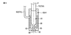
図5は、ケーシング10Aの内部に設けられるある1つの噴射本体部65A1の構成を示す図である。なお、以下の説明では、噴射本体部65A1についてのみ説明するが、噴射本体部65A2〜65A6,65B1〜65B6,65C1〜65C6においても、噴射本体部65A1と同様にして、路面に向かって水(液体)が噴射される。   FIG. 5 is a diagram showing a configuration of one injection main body 65A1 provided inside the casing 10A. In the following description, only the injection main body portion 65A1 will be described. However, in the injection main body portions 65A2 to 65A6, 65B1 to 65B6, 65C1 to 65C6, water (liquid) is directed toward the road surface in the same manner as the injection main body portion 65A1. ) Is injected.

図5に示すように、噴射本体部65A1は、通路軸Pに沿って延設される送液通路81を備える。通路軸Pは、噴射本体部65A1の中心軸と略同軸であり、鉛直方向に対して平行である。送液通路81の一端(鉛直下方向側の端)には、噴射口82が設けられている。噴射口82は、ケーシング10Aの内部に位置している。送液通路81の他端(鉛直上方向側の端)は、液体導入部70のサブ液体供給通路72Aと連通している。送液通路81には、サブ液体供給通路72Aを通して、水(液体)が導入される。そして、噴射口82に向かって、送液通路81において、水が送液される。したがって、噴射本体部65A1では、鉛直下方向が送液方向となり、噴射口82は、送液通路81の送液方向側の端に位置している。   As shown in FIG. 5, the injection main body portion 65 </ b> A <b> 1 includes a liquid feeding passage 81 that extends along the passage axis P. The passage axis P is substantially coaxial with the central axis of the injection main body 65A1 and is parallel to the vertical direction. An injection port 82 is provided at one end (vertical lower end) of the liquid supply passage 81. The injection port 82 is located inside the casing 10A. The other end (vertically upward end) of the liquid supply passage 81 communicates with the sub liquid supply passage 72A of the liquid introduction unit 70. Water (liquid) is introduced into the liquid supply passage 81 through the sub liquid supply passage 72A. Then, water is fed in the liquid feed passage 81 toward the injection port 82. Therefore, in the ejection main body 65A1, the vertically downward direction is the liquid feeding direction, and the ejection port 82 is located at the end of the liquid feeding passage 81 on the liquid feeding direction side.

また、送液通路81には、断面積減少部83が設けられている。断面積減少部83では、送液通路81の他の部分に比べて、通路軸Pに垂直な断面積が、部分的に小さくなる。このため、断面積減少部83では、ベンチュリー効果と同様の原理によって、送液される水の流速が大きくなり、液体導入部70及び送液通路81の他の部分に比べて、水の圧力が小さくなる。   Further, the liquid feeding passage 81 is provided with a cross-sectional area reducing portion 83. In the cross-sectional area reducing portion 83, the cross-sectional area perpendicular to the passage axis P is partially smaller than that in other portions of the liquid feeding passage 81. For this reason, in the cross-sectional area reduction part 83, the flow rate of the water to be sent is increased by the same principle as the Venturi effect, and the pressure of the water is higher than that of the other part of the liquid introduction part 70 and the liquid feed passage 81. Get smaller.

噴射本体部65A1には、送気通路85が形成されている。送気通路85は、通路軸Pに対して略垂直に延設されている。送気通路85は、断面積減少部83で送液通路81と連通している。また、噴射本体部65A1には、中継空気通路86が形成されている。中継空気通路86は、通路軸Pに対して略平行に延設されている。中継空気通路86の一端(鉛直上方向側の端)は、空気導入部50のサブ空気供給通路57Aと連通している。中継空気通路86の他端(鉛直下方向側の端)は、送気通路85と連通している。送気通路85には、サブ空気供給通路57A及び中継空気通路86を通して、空気(圧縮空気)が導入される。すなわち、ケーシング10Aの外部のエアタンク42から空気が、送気通路85に導入される。   An air supply passage 85 is formed in the injection main body portion 65A1. The air supply passage 85 extends substantially perpendicularly to the passage axis P. The air supply passage 85 communicates with the liquid supply passage 81 at the cross-sectional area reducing portion 83. Further, a relay air passage 86 is formed in the injection main body portion 65A1. The relay air passage 86 extends substantially parallel to the passage axis P. One end (vertically upward end) of the relay air passage 86 communicates with the sub air supply passage 57 </ b> A of the air introduction unit 50. The other end (vertical lower end) of the relay air passage 86 communicates with the air supply passage 85. Air (compressed air) is introduced into the air supply passage 85 through the sub air supply passage 57 </ b> A and the relay air passage 86. That is, air is introduced into the air supply passage 85 from the air tank 42 outside the casing 10A.

前述のように、断面積減少部83では、送液される水の圧力が小さくなる。このため、送気通路85に導入された空気は、送気通路85において、送液通路81の断面積減少部83に向かって吸引される。すなわち、送気通路85を通して、送液通路81の断面積減少部83に向かって、空気が送気される。断面積減少部83に空気が送気されることにより、送液通路81を通って送液される水(液体)に、気泡88が発生する。   As described above, in the cross-sectional area reducing portion 83, the pressure of the water to be fed is reduced. For this reason, the air introduced into the air supply passage 85 is sucked toward the cross-sectional area reducing portion 83 of the liquid supply passage 81 in the air supply passage 85. That is, air is supplied through the air supply passage 85 toward the cross-sectional area reducing portion 83 of the liquid supply passage 81. When air is supplied to the cross-sectional area reducing portion 83, bubbles 88 are generated in water (liquid) supplied through the liquid supply passage 81.

前述のように、アスピレータにおいて送液される液体に空気を流入させる原理と同様にして、噴射本体部65A1では、送液通路81で送液される水に空気を送気している。断面積減少部83において気泡88が発生した水(液体)は、噴射本体部65A1の噴射口82から、路面に向かって噴射される。   As described above, in the same manner as the principle of allowing air to flow into the liquid fed by the aspirator, the jet main body 65A1 feeds air to the water fed through the liquid feeding passage 81. The water (liquid) in which the bubbles 88 are generated in the cross-sectional area reducing portion 83 is jetted from the jet port 82 of the jet main body 65A1 toward the road surface.

次に、路面清掃車1の作用及び効果について、説明する。路面清掃車1により路面を清掃する場合は、運転室5で操作が行われる。まず、エアタンク42の空気がエアコンプレッサ41によって圧縮される。そして、メイン空気供給通路55を通して、圧縮空気が水タンク25へ供給される。そして、水タンク25から、液体導入部70(メイン液体供給通路71及びサブ液体供給通路72A〜72C)を通して、噴射本体部65A1〜65A6,65B1〜65B2,65C1〜65C6に水(液体)が導入される。それぞれの噴射本体部65A1〜65A6,65B1〜65B2,65C1〜65C6への水の供給状態は、コック75,76A〜76Cによって、調整される。   Next, the operation and effect of the road cleaning vehicle 1 will be described. When the road surface is cleaned by the road surface cleaning vehicle 1, the operation is performed in the cab 5. First, the air in the air tank 42 is compressed by the air compressor 41. The compressed air is supplied to the water tank 25 through the main air supply passage 55. Then, water (liquid) is introduced from the water tank 25 to the ejection main body portions 65A1 to 65A6, 65B1 to 65B2, and 65C1 to 65C6 through the liquid introduction portion 70 (the main liquid supply passage 71 and the sub liquid supply passages 72A to 72C). The The supply state of water to each of the injection main body portions 65A1 to 65A6, 65B1 to 65B2, 65C1 to 65C6 is adjusted by the cocks 75 and 76A to 76C.

また、エアコンプレッサ41によって圧縮された空気(圧縮空気)は、空気導入部50(メイン液体供給通路55及びサブ液体供給通路57A〜57C)を通して、噴射本体部65A1〜65A6,65B1〜65B2,65C1〜65C6に導入される。それぞれの噴射本体部65A1〜65A6,65B1〜65B2,65C1〜65C6への空気の供給状態は、コック61,66A〜66Cによって、調整される。   Further, the air (compressed air) compressed by the air compressor 41 passes through the air introduction part 50 (the main liquid supply passage 55 and the sub liquid supply passages 57A to 57C), and the injection main body parts 65A1 to 65A6, 65B1 to 65B2, 65C1. Introduced in 65C6. The supply state of air to each of the injection main body portions 65A1 to 65A6, 65B1 to 65B2, 65C1 to 65C6 is adjusted by the cocks 61 and 66A to 66C.

それぞれの噴射本体部65A1〜65A6,65B1〜65B2,65C1〜65C6では、液体導入部70から送液通路81に水(液体)が導入される。そして、送液通路81において、噴射口82に向かって、水が送液される。ここで、断面積減少部83では、ベンチュリー効果と同様の原理によって、送液される水の流速が大きくなり、液体導入部70及び送液通路81の他の部分に比べて、水の圧力が小さくなる。   In each of the ejection main body portions 65A1 to 65A6, 65B1 to 65B2, and 65C1 to 65C6, water (liquid) is introduced from the liquid introduction portion 70 into the liquid feeding passage 81. Then, in the liquid supply passage 81, water is supplied toward the injection port 82. Here, in the cross-sectional area reducing part 83, the flow rate of the water to be sent is increased by the same principle as the Venturi effect, and the pressure of the water is higher than that of the other part of the liquid introduction part 70 and the liquid feeding passage 81. Get smaller.

また、それぞれの噴射本体部65A1〜65A6,65B1〜65B2,65C1〜65C6では、空気導入部50から中継空気通路86を通して、送気通路85に空気が導入される。それぞれの噴射本体部65A1〜65A6,65B1〜65B2,65C1〜65C6には、ケーシング10A,10Bの外部のエアタンク42の空気が、導入される。   In each of the injection main body portions 65A1 to 65A6, 65B1 to 65B2, and 65C1 to 65C6, air is introduced from the air introduction unit 50 through the relay air passage 86 into the air supply passage 85. Air in the air tank 42 outside the casings 10A and 10B is introduced into each of the injection main body portions 65A1 to 65A6, 65B1 to 65B2, and 65C1 to 65C6.

断面積減少部83では、送液される水の圧力が小さくなるため、送気通路85に導入された空気は、送気通路85において、送液通路81の断面積減少部83に向かって吸引される。すなわち、送気通路85を通して、送液通路81の断面積減少部83に向かって、空気が送気される。断面積減少部83に空気が送気されることにより、送液通路81を通って送液される水(液体)に、気泡88が発生する。そして、それぞれの噴射本体部65A1〜65A6,65B1〜65B2,65C1〜65C6では、断面積減少部83において気泡88が発生した水(液体)が、噴射口82から路面に向かって噴射される。   In the cross-sectional area reducing portion 83, the pressure of water to be fed is reduced, so that the air introduced into the air feeding passage 85 is sucked toward the cross-sectional area reducing portion 83 of the liquid feeding passage 81 in the air feeding passage 85. Is done. That is, air is supplied through the air supply passage 85 toward the cross-sectional area reducing portion 83 of the liquid supply passage 81. When air is supplied to the cross-sectional area reducing portion 83, bubbles 88 are generated in water (liquid) supplied through the liquid supply passage 81. And in each injection main-body part 65A1-65A6, 65B1-65B2, 65C1-65C6, the water (liquid) which the bubble 88 generate | occur | produced in the cross-sectional area reduction | decrease part 83 is injected toward the road surface from the injection port 82. FIG.

噴射された液体に含まれる気泡88は、路面又は路面の近傍で、崩壊する。気泡88が崩壊する際に生じるマイクロジェット、衝撃波等のエネルギーによって、路面の隙間に入込んだ土砂、粉塵等の目詰まり物を浮き上がらせる。そして、浮き上がった目詰まり物を、吸引ユニット15によって吸引する。この際、噴射ユニット40によって噴射された水も汚水(汚液)として吸引されるとともに、空気も吸引される。気泡88が崩壊する際に生じるエネルギーを用いることにより、効率的に目詰まり物を浮き上がらせることができ、目詰まり物が効率的に吸引される。   Bubbles 88 contained in the ejected liquid collapse on the road surface or in the vicinity of the road surface. Clogged materials such as earth and sand and dust that have entered the gaps in the road surface are lifted by energy such as micro jets and shock waves generated when the bubbles 88 collapse. Then, the clogged material that has floated is sucked by the suction unit 15. At this time, water jetted by the jetting unit 40 is also sucked as sewage (dirt liquid) and air is sucked. By using the energy generated when the bubbles 88 collapse, the clogging can be efficiently lifted, and the clogging can be efficiently sucked.

目詰まり物、汚水及び空気は、ケーシング10Aの内部の吸引口19Aから吸引通路17Aを通して、又は、ケーシング10Bの内部の吸引口19Bから吸引通路17Bを通して、吸引される。そして、吸引通路17A又は吸引通路17Bを通った空気は、ホッパー21の第1の空洞部22に導かれる。第1の空洞部22では、吸引通路17A,17Bに比べ体積が大きいため、第1の空洞部22では圧力が急激に低下する。このため、吸引された空気から、目詰まり物及び汚水が分離される。そして、第1の空洞部22に目詰まり物が堆積され、汚水タンク26に汚水が溜められる。   The clogging, sewage and air are sucked from the suction port 19A inside the casing 10A through the suction passage 17A or from the suction port 19B inside the casing 10B through the suction passage 17B. The air that has passed through the suction passage 17 </ b> A or the suction passage 17 </ b> B is guided to the first cavity 22 of the hopper 21. Since the volume of the first cavity portion 22 is larger than that of the suction passages 17A and 17B, the pressure rapidly decreases in the first cavity portion 22. For this reason, clogging and sewage are separated from the sucked air. Then, clogging substances are accumulated in the first cavity portion 22 and the sewage is stored in the sewage tank 26.

そして、吸引された空気は、スクリーン28によって浄化され、第2の空洞部23に送気される。第2の空洞部23では、吸引された空気は、スクリーン28によって浄化されるため、目詰まり物等がほとんど含まれない。そして、ブロワー30を通して、ホッパー21の第2の空洞部23から機関室31の第3の空洞部32に、浄化された空気が送気される。そして、第3の空洞部32から排気口35を通して、外装カバー6の外部に空気が送気される。   The sucked air is purified by the screen 28 and is sent to the second cavity 23. In the second cavity 23, the sucked air is purified by the screen 28, so that clogged materials and the like are hardly included. Then, the purified air is supplied from the second cavity 23 of the hopper 21 to the third cavity 32 of the engine room 31 through the blower 30. Then, air is sent from the third cavity portion 32 through the exhaust port 35 to the outside of the exterior cover 6.

前述のように、本実施形態の路面清掃車1では、それぞれの噴射本体部65A1〜65A6,65B1〜65B2,65C1〜65C6において、送液通路81の断面積減少部83に、送気通路85を通して空気が送気される。すなわち、アスピレータにおいて送液される液体に空気を流入させる原理と同様にして、それぞれの噴射本体部65A1〜65A6,65B1〜65B2,65C1〜65C6において、送液通路81で送液される水に空気を送気している。したがって、高圧の水(液体)が送液通路81に導入されない場合でも、断面積減少部83で送液される水(液体)に気泡88が発生する。このため、本実施形態の路面清掃車1では、高圧の液体を生成する必要がなく、大型で、重量が大きい高出力のポンプを設ける必要はない。これにより、路面清掃車1の大型化及び重量化が有効に防止され、吸引した目詰まり物の積載量も大きくなる。また、高出力のポンプが設けられないため、騒音も有効に防止される。   As described above, in the road cleaning vehicle 1 of the present embodiment, in each of the injection main body portions 65A1 to 65A6, 65B1 to 65B2, and 65C1 to 65C6, the cross section area decreasing portion 83 of the liquid supply passage 81 is passed through the air supply passage 85. Air is sent. That is, in the same manner as the principle of flowing air into the liquid fed in the aspirator, in each of the injection main body portions 65A1 to 65A6, 65B1 to 65B2, and 65C1 to 65C6, air is supplied to the water fed in the liquid feeding passage 81. Is inflating. Therefore, even when high-pressure water (liquid) is not introduced into the liquid feeding passage 81, bubbles 88 are generated in the water (liquid) fed by the cross-sectional area reducing unit 83. For this reason, in the road surface cleaning vehicle 1 of this embodiment, it is not necessary to generate a high-pressure liquid, and it is not necessary to provide a high-power pump that is large and heavy. Thereby, the enlargement and weight increase of the road surface cleaning vehicle 1 are effectively prevented, and the loaded amount of the clogged clogged material is also increased. In addition, since no high-output pump is provided, noise is effectively prevented.

また、空気導入部50は、ケーシング10A,10Bの外部のエアタンク42から、空気をそれぞれの噴射本体部65A1〜65A6,65B1〜65B2,65C1〜65C6の送気通路85に導入する。ケーシング10A,10Bの内部では空気に、目詰まり物が混在している。これに対し、エアタンク42は、ケーシング10A,10Bの外部に位置し、エアタンク42から空気には目詰まり物等が混在していない。したがって、エアタンク42から空気が送気通路85に導入されることにより、送液通路81の断面積減少部83に送気される空気には、目詰まり物等が混在されない。これにより、それぞれの噴射本体部65A1〜65A6,65B1〜65B2,65C1〜65C6において、送液通路の81での目詰まり物の滞留が有効に防止され、送液通路81を通って送液される水の汚染が有効に防止される。   Moreover, the air introduction part 50 introduces air from the air tank 42 outside the casings 10A and 10B to the air supply passages 85 of the respective injection main body parts 65A1 to 65A6, 65B1 to 65B2, 65C1 to 65C6. In the casings 10A and 10B, clogging substances are mixed in the air. On the other hand, the air tank 42 is located outside the casings 10 </ b> A and 10 </ b> B, and no clogging or the like is mixed in the air from the air tank 42. Therefore, when air is introduced from the air tank 42 into the air supply passage 85, clogged materials or the like are not mixed in the air supplied to the cross-sectional area reducing portion 83 of the liquid supply passage 81. As a result, in each of the injection main body portions 65A1 to 65A6, 65B1 to 65B2, 65C1 to 65C6, the clogging of the clogging material in the liquid supply passage 81 is effectively prevented, and the liquid is supplied through the liquid supply passage 81. Water contamination is effectively prevented.

(第2の実施形態)
次に、本発明の第2の実施形態について図6乃至図12を参照して説明する。なお、第1の実施形態と同一の部分及び同一の機能を有する部分については同一の符号を付して、その説明は省略する。
(Second Embodiment)
Next, a second embodiment of the present invention will be described with reference to FIGS. In addition, the same code | symbol is attached | subjected about the part which has the same function as 1st Embodiment, and the same function, and the description is abbreviate | omitted.

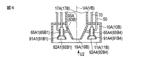
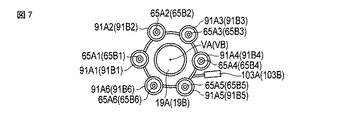
図6は、本実施形態のある1つのケーシング10Aの内部構成を示す図である。図7は、図6を矢印U2の方向から視た図である。なお、以下の説明では、ケーシング10Aの内部構成についてのみ説明するが、ケーシング10Bの内部構成についても、ケーシング10Aの内部構成と同様である。図6及び図7に示すように、本実施形態でも第1の実施形態と同様に、噴射本体部65A1〜65A6は、吸引通路17Aの吸引軸VAを中心として同心状に、配置されている。吸引通路17Aの吸引口19Aは、噴射本体部65A1〜65A6によって、囲まれている。そして、噴射本体部65A1〜65A6に、空気導入部50のサブ空気供給通路57A及び液体導入部70のサブ液体供給通路72Aが接続されている。   FIG. 6 is a diagram showing an internal configuration of one casing 10A according to the present embodiment. FIG. 7 is a view of FIG. 6 viewed from the direction of the arrow U2. In the following description, only the internal configuration of the casing 10A will be described, but the internal configuration of the casing 10B is the same as the internal configuration of the casing 10A. As shown in FIGS. 6 and 7, in the present embodiment as well, the injection main body portions 65A1 to 65A6 are arranged concentrically around the suction axis VA of the suction passage 17A as in the first embodiment. The suction port 19A of the suction passage 17A is surrounded by the injection main body portions 65A1 to 65A6. And the sub air supply passage 57A of the air introduction part 50 and the sub liquid supply passage 72A of the liquid introduction part 70 are connected to the injection main body parts 65A1 to 65A6.

本実施形態では、それぞれの噴射本体部65A1〜65A6の送液方向側(鉛直下方向側)に、対応する拡散筒状部91A1〜91A6が設けられている。それぞれの拡散筒状部91A1〜91A6の内部には、空洞部92A1〜92A6が形成されている。拡散筒状部91A1〜91A6は、駆動リング93Aを介して、互いに対して連結されている。駆動リング93Aは、吸引軸VAを中心として環状に延設されている。   In the present embodiment, corresponding diffusion cylindrical portions 91A1 to 91A6 are provided on the liquid feeding direction side (vertical downward direction side) of the respective injection main body portions 65A1 to 65A6. Cavities 92A1 to 92A6 are formed inside the diffusion cylindrical portions 91A1 to 91A6. The diffusion cylindrical portions 91A1 to 91A6 are connected to each other via a drive ring 93A. The drive ring 93A extends in an annular shape around the suction axis VA.

なお、それぞれの噴射本体部65B1〜65B6の送液方向側にも、対応する拡散筒状部91B1〜91B6が設けられ、それぞれの拡散筒状部91B1〜91B6の内部には、空洞部92B1〜92B6が形成されている。そして、拡散筒状部91B1〜91B6は、駆動リング93Bを介して、互いに対して連結されている。   Note that corresponding diffusion cylindrical portions 91B1 to 91B6 are also provided on the liquid feeding direction sides of the respective injection main body portions 65B1 to 65B6, and inside the diffusion cylindrical portions 91B1 to 91B6, the cavity portions 92B1 to 92B6 are provided. Is formed. The diffusion cylindrical portions 91B1 to 91B6 are connected to each other via the drive ring 93B.

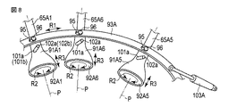
図8は、ある1つのケーシング10Aの内部に設けられる駆動リング93Aの構成を示す図である。また、図9乃至図12は、ケーシング10Aの内部に設けられるある1つの噴射本体部65A1及びある1つの拡散筒状部91A1の構成を示す図である。なお、以下の説明では、駆動リング93Aについてのみ説明するが、駆動リング93Bについても、駆動リング93Aと同様にして、駆動される。また、以下の説明では、噴射本体部65A1及び拡散筒状部91A1についてのみ説明するが、噴射本体部65A2〜65A6,65B1〜65B6及び拡散筒状部91A2〜92A6,92B1〜92B6においても、噴射本体部65A1及び拡散筒状部91A1と同様にして、駆動され、路面に向かって水(液体)が噴射される。   FIG. 8 is a diagram illustrating a configuration of a drive ring 93A provided inside one casing 10A. 9 to 12 are diagrams showing the configuration of one injection main body 65A1 and one diffusion cylindrical portion 91A1 provided inside the casing 10A. In the following description, only the drive ring 93A is described, but the drive ring 93B is also driven in the same manner as the drive ring 93A. Further, in the following description, only the injection main body 65A1 and the diffusion cylindrical portion 91A1 will be described, but the injection main body 65A2 to 65A6, 65B1 to 65B6 and the diffusion cylindrical portions 91A2 to 92A6 and 92B1 to 92B6 are also injection main bodies. It is driven in the same manner as the portion 65A1 and the diffusion tubular portion 91A1, and water (liquid) is jetted toward the road surface.

図8乃至図12に示すように、駆動リング93Aには、駆動リング93Aを貫通する6つの孔状部95が設けられている。拡散筒状部91A1は、連結ピン96を介して、駆動リング93Aに取付けられる。すなわち、連結ピン96が対応する孔状部95に挿通され、拡散筒状部91A1に固定されることにより、拡散筒状部91A1が駆動リング93Aに取付けられる。   As shown in FIGS. 8 to 12, the drive ring 93A is provided with six hole portions 95 penetrating the drive ring 93A. The diffusion cylindrical portion 91A1 is attached to the drive ring 93A via the connecting pin 96. That is, the linking pin 96 is inserted into the corresponding hole 95 and fixed to the diffusion cylinder 91A1, whereby the diffusion cylinder 91A1 is attached to the drive ring 93A.

また、拡散筒状部91A1には、拡散筒状部91A1を貫通する2つのスリット部101a,101bが設けられている。拡散筒状部91A1は、2つの連結ピン102a,102bを介して、噴射本体部65A1に取付けられる。すなわち、それぞれの連結ピン102a,102bが対応するスリット部101a,101bに挿通され、噴射本体部65A1に固定されることにより、拡散筒状部91A1が噴射本体部65A1に取付けられる。ここで、スリット部101a,101bは、送液通路81の通路軸Pに対して傾斜する斜方方向に沿って延設されている。すなわち、スリット部101a,101bは、通路軸Pを中心として螺旋状に延設されている。   The diffusion cylindrical portion 91A1 is provided with two slit portions 101a and 101b that penetrate the diffusion cylindrical portion 91A1. The diffusion cylindrical portion 91A1 is attached to the injection main body portion 65A1 via the two connecting pins 102a and 102b. That is, the diffusion cylindrical portion 91A1 is attached to the injection main body 65A1 by inserting the connecting pins 102a and 102b through the corresponding slit portions 101a and 101b and fixing them to the injection main body 65A1. Here, the slit portions 101 a and 101 b are extended along an oblique direction inclined with respect to the passage axis P of the liquid feeding passage 81. That is, the slit portions 101a and 101b extend in a spiral shape with the passage axis P as the center.

また、駆動リング93Aには、シリンダー103Aが取付けられている。シリンダー103Aが伸縮することにより、駆動リング93Aは駆動され、吸引軸VAを中心として駆動リング93Aが回動する(図8の矢印R1)。これにより、駆動リング93Aから連結ピン96を介して、拡散筒状部91A1に駆動力が伝達される。駆動力が伝達されることにより、拡散筒状部91A1は、噴射本体部65A1に対して、スリット部101a,101bが延設される斜方方向に沿って移動する。すなわち、拡散筒状部91A1は、噴射本体部65A1に対して、通路軸Pを中心として回動するとともに(図8の矢印R2)、通路軸Pに沿って移動する(図8の矢印R3)。   A cylinder 103A is attached to the drive ring 93A. When the cylinder 103A expands and contracts, the drive ring 93A is driven, and the drive ring 93A rotates around the suction axis VA (arrow R1 in FIG. 8). As a result, the driving force is transmitted from the driving ring 93A to the diffusing cylindrical portion 91A1 via the connecting pin 96. When the driving force is transmitted, the diffusion cylindrical portion 91A1 moves along the oblique direction in which the slit portions 101a and 101b are extended with respect to the injection main body portion 65A1. That is, the diffusion cylindrical portion 91A1 rotates about the passage axis P with respect to the injection main body portion 65A1 (arrow R2 in FIG. 8) and moves along the passage axis P (arrow R3 in FIG. 8). .

拡散筒状部91A1は、噴射本体部65A1に対して、非拡散位置(図9及び図10に示す位置)と拡散位置(図11及び図12に示す位置)との間で、移動可能である。非拡散位置は拡散筒状部91A1の移動範囲において最も鉛直上方向側の位置であり、拡散位置は拡散筒状部91A1の移動範囲において最も鉛直下方向側の位置である。なお、図10は図9を矢印S1の方向から視た図であり、図12は図11を矢印S2の方向から視た図である。   The diffusion cylindrical portion 91A1 is movable with respect to the injection main body portion 65A1 between a non-diffusion position (position shown in FIGS. 9 and 10) and a diffusion position (position shown in FIGS. 11 and 12). . The non-diffusion position is the position on the most vertically upward side in the movement range of the diffusion cylindrical part 91A1, and the diffusion position is the position on the most vertically downward side in the movement range of the diffusion cylindrical part 91A1. 10 is a view of FIG. 9 viewed from the direction of arrow S1, and FIG. 12 is a view of FIG. 11 viewed from the direction of arrow S2.

本実施形態でも第1の実施形態と同様に、噴射本体部65A1には、送液通路81、送気通路85及び中継空気通路86が設けられている。そして、送液通路81には、噴射口82及び断面積減少部83が、設けられている。本実施形態では、拡散筒状部91A1の内部の空洞部92A1は、噴射口82で送液通路81と連通している。拡散筒状部91A1では、送液方向に向かうにつれて、通路軸Pに垂直な空洞部92A1の断面積が大きくなる。本実施形態では、拡散筒状部91A1は、スカート状に形成されている。   Also in the present embodiment, as in the first embodiment, the injection main body portion 65A1 is provided with a liquid supply passage 81, an air supply passage 85, and a relay air passage 86. The liquid feed passage 81 is provided with an injection port 82 and a cross-sectional area reducing portion 83. In the present embodiment, the hollow portion 92 </ b> A <b> 1 inside the diffusion cylindrical portion 91 </ b> A <b> 1 communicates with the liquid feeding passage 81 at the injection port 82. In diffusion cylindrical part 91A1, the cross-sectional area of hollow part 92A1 perpendicular | vertical to channel | path axis P becomes large as it goes to a liquid feeding direction. In the present embodiment, the diffusion cylindrical portion 91A1 is formed in a skirt shape.

また、本実施形態では、中継空気通路86は、送気通路85と連通するとともに、拡散筒状部91A1の内部の空洞部92A1と連通している。中継空気通路86は、空気流出口105で、空洞部92A1と連通している。本実施形態でも第1の実施形態と同様に、送気通路85には、サブ空気供給通路57A及び中継空気通路86を通して、空気(圧縮空気)が導入される。すなわち、ケーシング10Aの外部のエアタンク42から空気が、送気通路85に導入される。また、本実施形態では、サブ空気供給通路57A及び中継空気通路86を通して、空気流出口105から空洞部92A1に空気が導入される。   In the present embodiment, the relay air passage 86 communicates with the air supply passage 85 and also communicates with the hollow portion 92A1 inside the diffusion cylindrical portion 91A1. The relay air passage 86 communicates with the hollow portion 92A1 at the air outlet 105. Also in the present embodiment, air (compressed air) is introduced into the air supply passage 85 through the sub air supply passage 57A and the relay air passage 86 as in the first embodiment. That is, air is introduced into the air supply passage 85 from the air tank 42 outside the casing 10A. In the present embodiment, air is introduced from the air outlet 105 into the cavity 92A1 through the sub air supply passage 57A and the relay air passage 86.

拡散筒状部91A1は、空洞部92A1を規定する内周部107と、路面に向かって開口する開口部108と、を備える。図9及び図10に示すように、拡散筒状部91A1が非拡散位置に位置する場合は、拡散筒状部91A1の内周部107は、空気流出口105から拡散筒状部91A1の径方向に離れて位置している。このため、空気流出口105から空洞部92A1に空気が導入されても、空気は拡散筒状部91A1の内周部107に沿って移動せず、拡散筒状部91A1の径方向について内周部107から離れた位置を通って路面に向かう。このため、拡散筒状部91A1が非拡散位置に位置する場合には、噴射本体部65A1の噴射口82から噴射された水(液体)が、空洞部92A1で拡散されない。すなわち、気泡88が発生した水(液体)は、噴射口82から噴射された後に拡散されることなく、路面に向かう。   The diffusion cylindrical portion 91A1 includes an inner peripheral portion 107 that defines the hollow portion 92A1 and an opening 108 that opens toward the road surface. As shown in FIGS. 9 and 10, when the diffusion cylindrical portion 91A1 is located at the non-diffusion position, the inner peripheral portion 107 of the diffusion cylindrical portion 91A1 is arranged in the radial direction of the diffusion cylindrical portion 91A1 from the air outlet 105. Located away. For this reason, even if air is introduced into the hollow portion 92A1 from the air outlet 105, the air does not move along the inner peripheral portion 107 of the diffusion cylindrical portion 91A1, but the inner peripheral portion in the radial direction of the diffusion cylindrical portion 91A1. Go to the road surface through a position away from 107. For this reason, when diffusion cylindrical part 91A1 is located in a non-diffusion position, the water (liquid) injected from the injection port 82 of injection main-body part 65A1 is not diffused by cavity part 92A1. That is, the water (liquid) in which the bubbles 88 are generated travels toward the road surface without being diffused after being ejected from the ejection port 82.

一方、図11及び図12に示すように、拡散筒状部91A1が拡散位置に位置する場合は、拡散筒状部91A1の径方向について、拡散筒状部91A1の内周部107は空気流出口105の近傍に、位置している。このため、空気流出口105から空洞部92A1に空気が導入されることにより、空気は拡散筒状部91A1の内周部107に沿って移動する。このため、空洞部92A1において、拡散筒状部91A1の内周部107に沿って路面に向かう空気の流れf1が発生する。前述のように、拡散筒状部91A1では、送液方向(路面)に向かうにつれて、通路軸Pに垂直な空洞部92A1の断面積が大きくなる。このため、拡散筒状部91A1の内周部107に沿った空気の流れf1が発生することにより、噴射本体部65A1の噴射口82から噴射された水(液体)が、空洞部92A1で拡散される。すなわち、拡散筒状部91A1が拡散位置に位置する場合には、気泡88が発生した水(液体)は、噴射口82から噴射された後に拡散筒状部91A1の内周部107に沿った空気の流れf1によって拡散され、路面に向かう。   On the other hand, as shown in FIGS. 11 and 12, when the diffusion tubular portion 91A1 is located at the diffusion position, the inner peripheral portion 107 of the diffusion tubular portion 91A1 is the air outlet in the radial direction of the diffusion tubular portion 91A1. It is located in the vicinity of 105. For this reason, when air is introduced into the hollow portion 92A1 from the air outlet 105, the air moves along the inner peripheral portion 107 of the diffusion tubular portion 91A1. For this reason, in the hollow portion 92A1, an air flow f1 toward the road surface is generated along the inner peripheral portion 107 of the diffusion tubular portion 91A1. As described above, in the diffusion cylindrical portion 91A1, the cross-sectional area of the hollow portion 92A1 perpendicular to the passage axis P increases in the liquid feeding direction (road surface). For this reason, when the air flow f1 along the inner peripheral portion 107 of the diffusion cylindrical portion 91A1 is generated, the water (liquid) injected from the injection port 82 of the injection main body portion 65A1 is diffused in the cavity portion 92A1. The That is, when the diffusion cylindrical portion 91A1 is located at the diffusion position, the water (liquid) in which the bubbles 88 are generated is air along the inner peripheral portion 107 of the diffusion cylindrical portion 91A1 after being ejected from the ejection port 82. It is diffused by the flow f1 and heads for the road surface.

噴射口82から噴射された水が拡散筒状部91A1の内部の空洞部92A2で拡散されることにより、気泡88が発生した水が広範囲に散布される。したがって、拡散筒状部91A1が拡散位置に位置する場合には、1つの噴射口82から噴射される水(液体)によって、広範囲の目詰まり物を浮き上がらせることができる。   The water ejected from the ejection port 82 is diffused in the hollow portion 92A2 inside the diffusion cylindrical portion 91A1, so that the water in which the bubbles 88 are generated is dispersed over a wide range. Therefore, when the diffusion cylindrical portion 91A1 is located at the diffusion position, a wide range of clogged substances can be lifted by the water (liquid) ejected from one ejection port 82.

(第3の実施形態)
次に、本発明の第3の実施形態について図13及び図14を参照して説明する。なお、第2の実施形態と同一の部分及び同一の機能を有する部分については同一の符号を付して、その説明は省略する。
(Third embodiment)
Next, a third embodiment of the present invention will be described with reference to FIGS. In addition, the same code | symbol is attached | subjected about the part which has the same part as 2nd Embodiment, and the same function, and the description is abbreviate | omitted.

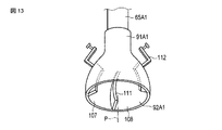
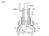
図13及び図14は、ケーシング10Aの内部に設けられるある1つの噴射本体部65A1及びある1つの拡散筒状部91A1の構成を示す図である。なお、以下の説明では、噴射本体部65A1及び拡散筒状部91A1についてのみ説明するが、噴射本体部65A2〜65A6,65B1〜65B6及び拡散筒状部91A2〜92A6,92B1〜92B6においても、噴射本体部65A1及び拡散筒状部91A1と同様にして、路面に向かって水(液体)が噴射される。   FIGS. 13 and 14 are diagrams showing the configuration of one injection main body 65A1 and one diffusion cylinder 91A1 provided inside the casing 10A. In the following description, only the injection main body portion 65A1 and the diffusion cylindrical portion 91A1 will be described, but the injection main body portions 65A2 to 65A6, 65B1 to 65B6 and the diffusion cylindrical portions 91A2 to 92A6 and 92B1 to 92B6 are also injection main bodies. In the same manner as the portion 65A1 and the diffusion tubular portion 91A1, water (liquid) is jetted toward the road surface.

図13及び図14に示すように、本実施形態では第2の実施形態とは異なり、ケーシング10A(10B)の内部に駆動リング93A(93B)は、設けられていない。したがって、拡散筒状部91A1は、噴射本体部65A1に対して通路軸Pに沿って移動不可能であり、噴射本体部65A1に対して固定されている。本実施形態では、第2の実施形態において拡散筒状部91A1が拡散位置に位置する場合と同様に、拡散筒状部91A1の径方向について、拡散筒状部91A1の内周部107は空気流出口105の近傍に、位置している。このため、空気流出口105から空洞部92A1に空気が導入されることにより、空気は拡散筒状部91A1の内周部107に沿って移動する。   As shown in FIGS. 13 and 14, in the present embodiment, unlike the second embodiment, the drive ring 93A (93B) is not provided in the casing 10A (10B). Accordingly, the diffusion cylindrical portion 91A1 is not movable along the passage axis P with respect to the injection main body portion 65A1, and is fixed with respect to the injection main body portion 65A1. In the present embodiment, in the same manner as in the case where the diffusion cylindrical portion 91A1 is located at the diffusion position in the second embodiment, the inner peripheral portion 107 of the diffusion cylindrical portion 91A1 is the air flow in the radial direction of the diffusion cylindrical portion 91A1. It is located in the vicinity of the outlet 105. For this reason, when air is introduced into the hollow portion 92A1 from the air outlet 105, the air moves along the inner peripheral portion 107 of the diffusion tubular portion 91A1.

本実施形態では、拡散筒状部91A1に、内周部107から通路軸Pに向かって突出する突起部111が設けられている。突起部111は、通路軸Pを中心として螺旋状に延設されている。突起部111が設けられることにより、空気流出口105から空洞部92A1に導入された空気は、通路軸Pを中心として螺旋状に移動し、路面に向かう。したがって、本実施形態では、空洞部92A1において、拡散筒状部91A1の内周部107に沿って、かつ、通路軸Pを中心として螺旋状に路面に向かう空気の流れf2が発生する。なお、拡散筒状部91A1には、内周部107に対する突起部111の角度を調整する突起角度調整レバー112が、取付けられている。   In the present embodiment, the diffusion cylindrical portion 91A1 is provided with a protrusion 111 that protrudes from the inner peripheral portion 107 toward the passage axis P. The protrusion 111 extends spirally around the passage axis P. By providing the projection 111, the air introduced from the air outlet 105 into the cavity 92A1 moves spirally around the passage axis P and travels toward the road surface. Therefore, in the present embodiment, in the hollow portion 92A1, an air flow f2 is generated along the inner peripheral portion 107 of the diffusion tubular portion 91A1 and spirally around the passage axis P toward the road surface. A projection angle adjusting lever 112 that adjusts the angle of the projection 111 with respect to the inner peripheral portion 107 is attached to the diffusion cylindrical portion 91A1.

本実施形態でも、拡散筒状部91A1では、送液方向(路面)に向かうにつれて、通路軸Pに垂直な空洞部92A1の断面積が大きくなる。このため、拡散筒状部91A1の内周部107に沿った空気の流れf2が発生することにより、噴射本体部65A1の噴射口82から噴射された水(液体)が、空洞部92A1で拡散される。また、本実施形態では、
空気の流れf2は通路軸Pを中心として螺旋状に路面に向かうため、通路軸Pから離れる方向に遠心力Fが発生する。遠心力Fが作用することにより、噴射本体部65A1の噴射口82から噴射された水が、さらに拡散される。すなわち、気泡88が発生した水(液体)は、噴射口82から噴射された後に拡散筒状部91A1の内周部107に沿った空気の流れf2及び遠心力Fによって拡散され、路面に向かう。
Also in this embodiment, in diffusion cylindrical part 91A1, the cross-sectional area of hollow part 92A1 perpendicular | vertical to channel | path axis P becomes large as it goes to a liquid feeding direction (road surface). For this reason, when the air flow f2 along the inner peripheral portion 107 of the diffusion cylindrical portion 91A1 is generated, the water (liquid) injected from the injection port 82 of the injection main body portion 65A1 is diffused in the cavity portion 92A1. The In this embodiment,
Since the air flow f2 spirals toward the road surface around the passage axis P, a centrifugal force F is generated in a direction away from the passage axis P. By the centrifugal force F acting, the water jetted from the jet port 82 of the jet main body 65A1 is further diffused. That is, the water (liquid) in which the bubbles 88 are generated is diffused by the air flow f2 and the centrifugal force F along the inner peripheral portion 107 of the diffusion cylindrical portion 91A1 after being ejected from the ejection port 82, and heads toward the road surface.

噴射口82から噴射された水が拡散筒状部91A1の内部の空洞部92A2で遠心力Fによってさらに拡散されることにより、気泡88が発生した水がさらに広範囲に散布される。したがって、1つの噴射口82から噴射される水(液体)によって、さらに広範囲において目詰まり物を浮き上がらせることができる。   The water jetted from the jet port 82 is further diffused by the centrifugal force F in the hollow portion 92A2 inside the diffusion cylindrical portion 91A1, so that the water in which the bubbles 88 are generated is spread over a wider range. Therefore, the clogged material can be lifted in a wider range by the water (liquid) ejected from one ejection port 82.

(変形例)
なお、前述の実施形態では、2つのケーシング10A,10Bが設けられ、それぞれのケーシング(10A,10B)の内部に1つの吸引口(19A,19B)及び6つの噴射本体部(65A1〜65A6,65B1〜65B6)が設けられているが、これに限るものではない。すなわち、ケーシング(10A,10B)の数、及び、それぞれのケーシング(10A,10B)の内部に位置する吸引口(19A,19B)の数及び噴射本体部(65A1〜65A6,65B1〜65B6)の数は、前述の実施形態に限るものではない。
(Modification)
In the above-described embodiment, two casings 10A and 10B are provided, and one suction port (19A and 19B) and six injection main bodies (65A1 to 65A6 and 65B1) are provided in the respective casings (10A and 10B). ~ 65B6) is provided, but is not limited thereto. That is, the number of casings (10A, 10B), the number of suction ports (19A, 19B) located inside each casing (10A, 10B), and the number of injection main bodies (65A1 to 65A6, 65B1 to 65B6) Is not limited to the above-described embodiment.

また、前述の実施形態では、送気通路85には、エアタンク42から空気導入部50を通して、空気(圧縮空気)が導入されるが、これに限るものではない。例えば、ケーシング10A,10Bの外部の大気(地上の空気)が、空気導入部50を通して送気通路85に導入されてもよい。すなわち、ケーシング10A,10Bの外部から、空気導入部50によって、空気が送気通路85に導入されればよい。   In the above-described embodiment, air (compressed air) is introduced into the air supply passage 85 from the air tank 42 through the air introduction unit 50, but is not limited thereto. For example, the atmosphere outside the casings 10 </ b> A and 10 </ b> B (ground air) may be introduced into the air supply passage 85 through the air introduction unit 50. In other words, air may be introduced into the air supply passage 85 from the outside of the casings 10 </ b> A and 10 </ b> B by the air introduction unit 50.

したがって、路面清掃車1は、路面に向かって開口する開口部(11A,11B)が形成されるケーシング(10A,10B)と、ケーシング(10A,10B)の内部に位置する吸引口(19A,19B)から吸引通路(17A,17B)を通して吸引を行う吸引ユニット(15)と、ケーシング(10A,10B)の内部に設けられる噴射本体部(65A1〜65A6,65B1〜65B6)を備え、ケーシング(10A,10B)の内部に位置する噴射口(82)から気泡(88)が発生した液体を路面に向かって噴射する噴射ユニット(40)と、を備えればよい。そして、噴射ユニット(40)の噴射本体部(65A1〜65A6,65B1〜65B6)は、通路軸(P)に沿って延設され、送液方向側の端に位置する噴射口(82)に向かって液体が送液される送液通路(81)を備え、送液通路(81)の断面積減少部(83)で、送液通路(81)の他の部分に比べて、通路軸(P)に垂直な断面積が部分的に小さくなればよい。そして、噴射本体部(65A1〜65A6,65B1〜65B6)は、断面積減少部(83)で送液通路(81)に連通し、送液通路(81)の断面積減少部(83)に向かって空気を送気することにより、液体に気泡(88)を発生させる送気通路(85)を備えればよい。そして、噴射ユニット(40)は、送液通路(81)に液体を導入する液体導入部(70)と、ケーシング(10A,10B)の外部から空気を送気通路(85)に導入する空気導入部(50)と、 を備えればよい。   Accordingly, the road cleaning vehicle 1 includes a casing (10A, 10B) in which openings (11A, 11B) that open toward the road surface are formed, and a suction port (19A, 19B) located inside the casing (10A, 10B). ) From the suction passage (17A, 17B) through the suction passage (17A, 17B) and the injection body (65A1 to 65A6, 65B1 to 65B6) provided inside the casing (10A, 10B), the casing (10A, And an injection unit (40) that injects the liquid, in which bubbles (88) are generated, from the injection port (82) located inside 10B) toward the road surface. The injection body (65A1 to 65A6, 65B1 to 65B6) of the injection unit (40) extends along the passage axis (P) and faces the injection port (82) located at the end on the liquid feeding direction side. The liquid supply passage (81) through which the liquid is supplied is provided, and the passage shaft (P) is compared with the other portion of the liquid supply passage (81) at the cross-sectional area reduction portion (83) of the liquid supply passage (81). It suffices if the cross-sectional area perpendicular to) is partially reduced. The injection main body portions (65A1 to 65A6, 65B1 to 65B6) communicate with the liquid feeding passage (81) at the cross-sectional area reducing portion (83) and head toward the cross-sectional area reducing portion (83) of the liquid feeding passage (81). It is only necessary to provide an air supply passage (85) for generating bubbles (88) in the liquid by supplying air. The injection unit (40) includes a liquid introduction part (70) for introducing liquid into the liquid supply passage (81), and an air introduction for introducing air into the air supply passage (85) from the outside of the casing (10A, 10B). The part (50) may be provided.

以上、本発明の実施形態について説明したが、本発明は上記の実施形態に限定されるものではなく、本発明の要旨を逸脱しない範囲で種々の変形ができることは勿論である。   The embodiments of the present invention have been described above. However, the present invention is not limited to the above-described embodiments, and various modifications can be made without departing from the scope of the present invention.

1…路面清掃車、10A,10B…ケーシング、11A,11B…開口部、15…吸引ユニット、17A,17B…吸引通路,19A,19B…吸引口、40…噴射ユニット、50…空気導入部、65A1〜65A6,65B1〜65B6…噴射本体部、81…送液通路、82…噴射口、83…断面積減少部、85送気通路、70…液体導入部。   DESCRIPTION OF SYMBOLS 1 ... Road cleaning car, 10A, 10B ... Casing, 11A, 11B ... Opening part, 15 ... Suction unit, 17A, 17B ... Suction passage, 19A, 19B ... Suction port, 40 ... Injection unit, 50 ... Air introduction part, 65A1 ˜65A6, 65B1 to 65B6... Injection main body portion, 81... Liquid feeding passage, 82... Jetting port, 83.

Claims (2)

路面に向かって開口する開口部が形成されるケーシングと、
前記ケーシングの内部に位置する吸引口から吸引通路を通して吸引を行う吸引ユニットと、
前記ケーシングの前記内部に設けられる噴射本体部を備え、前記ケーシングの前記内部に位置する噴射口から気泡が発生した液体を前記路面に向かって噴射する噴射ユニットと、
を具備し、
前記噴射ユニットの前記噴射本体部は、
通路軸に沿って延設され、送液方向側の端に位置する前記噴射口に向かって前記液体が送液される送液通路であって、前記通路軸に垂直な断面積が前記送液通路の他の部分に比べて部分的に小さくなる断面積減少部を備える送液通路と、
前記断面積減少部で前記送液通路に連通し、前記送液通路の前記断面積減少部に向かって空気を送気することにより、前記液体に前記気泡を発生させる送気通路と、
を備え、
前記噴射ユニットは、
前記送液通路に前記液体を導入する液体導入部と、
前記ケーシングの外部から前記空気を前記送気通路に導入する空気導入部と、
を備える路面清掃車。
A casing in which an opening that opens toward the road surface is formed;
A suction unit that performs suction through a suction passage from a suction port located inside the casing;
An injection unit that includes an injection main body provided inside the casing, and that injects liquid in which bubbles are generated from an injection port located inside the casing toward the road surface;
Comprising
The injection main body of the injection unit is
A liquid supply passage that extends along the passage axis and feeds the liquid toward the ejection port located at the end on the liquid feeding direction side, and has a cross-sectional area perpendicular to the passage axis. A liquid-feeding passage having a cross-sectional area reduction portion that is partially smaller than other portions of the passage;
An air-feeding passage that communicates with the liquid-feeding passage at the cross-sectional area reducing portion and feeds air toward the cross-sectional area reducing portion of the liquid-feeding passage to generate the bubbles in the liquid;
With
The injection unit is
A liquid introduction part for introducing the liquid into the liquid feeding path;
An air introduction part for introducing the air into the air supply passage from the outside of the casing;
Road sweeper equipped with.
前記噴射ユニットは、前記噴射本体部の前記送液方向側に設けられ、前記噴射口で前記送液通路と連通する空洞部が内部に形成される拡散筒状部であって、前記送液方向に向かうにつれて、前記通路軸に垂直な前記空洞部の断面積が大きくなる拡散筒状部を備え、
前記空気導入部は、空気流出口から前記拡散筒状部の前記内部の前記空洞部に前記空気を導入し、前記拡散筒状部の内周部に沿って前記路面に向かう前記空気の流れを発生させる、
請求項1の路面清掃車。
The injection unit is a diffusion cylindrical portion that is provided on the liquid supply direction side of the injection main body and in which a hollow portion that communicates with the liquid supply passage at the injection port is formed, and the liquid supply direction A diffusion tubular portion in which the cross-sectional area of the hollow portion perpendicular to the passage axis increases toward
The air introduction part introduces the air from the air outlet into the hollow part inside the diffusion cylindrical part, and flows the air flowing toward the road surface along the inner peripheral part of the diffusion cylindrical part. generate,
The road sweeper according to claim 1.
JP2012184373A 2012-08-23 2012-08-23 Road sweeper Active JP6018838B2 (en)

Priority Applications (1)

Application Number Priority Date Filing Date Title
JP2012184373A JP6018838B2 (en) 2012-08-23 2012-08-23 Road sweeper

Applications Claiming Priority (1)

Application Number Priority Date Filing Date Title
JP2012184373A JP6018838B2 (en) 2012-08-23 2012-08-23 Road sweeper

Publications (2)

Publication Number Publication Date
JP2014040748A true JP2014040748A (en) 2014-03-06
JP6018838B2 JP6018838B2 (en) 2016-11-02

Family

ID=50393192

Family Applications (1)

Application Number Title Priority Date Filing Date
JP2012184373A Active JP6018838B2 (en) 2012-08-23 2012-08-23 Road sweeper

Country Status (1)

Country Link
JP (1) JP6018838B2 (en)

Cited By (2)

* Cited by examiner, † Cited by third party
Publication number Priority date Publication date Assignee Title
CN108677831A (en) * 2018-07-26 2018-10-19 徐州徐工环境技术有限公司 car wash
CN109661489A (en) * 2016-08-29 2019-04-19 株式会社日阪制作所 The inorganic agent dissolver and liquid flow type cloth treatment device of liquid flow type cloth treatment device

Citations (8)

* Cited by examiner, † Cited by third party
Publication number Priority date Publication date Assignee Title
US4168562A (en) * 1977-01-08 1979-09-25 Woma-Apparatebau Wolfgang Maasberg & Co. Gmbh Surface-cleaning apparatus
JPH0760088A (en) * 1993-08-26 1995-03-07 Idec Izumi Corp Gas-liquid dissolution mixing device
JPH07236674A (en) * 1994-02-25 1995-09-12 Takagi Kogyo Kk Low power and low noise bubble generator for bubble jet bath
JPH07305308A (en) * 1994-05-12 1995-11-21 Fuji Kosan Kk Surface treatment method for resin asphalt pavement
JP2000037642A (en) * 1998-07-22 2000-02-08 Ebara Hiroyuki Shower apparatus
JP2001159110A (en) * 1999-12-03 2001-06-12 Babcock Hitachi Kk Road surface washing method for water permeable pavement, and washing apparatus
JP2003074032A (en) * 2001-08-30 2003-03-12 Hitachi Constr Mach Co Ltd Removing device for clogged object on pavement, draining function recovering device for pavement and removing method for clogged object on pavement
JP2003311691A (en) * 2002-04-22 2003-11-05 Mitsuhiro Minamimagoe Automatic waste collection equipment accompanying cutting and surface treatment by WJ.

Patent Citations (8)

* Cited by examiner, † Cited by third party
Publication number Priority date Publication date Assignee Title
US4168562A (en) * 1977-01-08 1979-09-25 Woma-Apparatebau Wolfgang Maasberg & Co. Gmbh Surface-cleaning apparatus
JPH0760088A (en) * 1993-08-26 1995-03-07 Idec Izumi Corp Gas-liquid dissolution mixing device
JPH07236674A (en) * 1994-02-25 1995-09-12 Takagi Kogyo Kk Low power and low noise bubble generator for bubble jet bath
JPH07305308A (en) * 1994-05-12 1995-11-21 Fuji Kosan Kk Surface treatment method for resin asphalt pavement
JP2000037642A (en) * 1998-07-22 2000-02-08 Ebara Hiroyuki Shower apparatus
JP2001159110A (en) * 1999-12-03 2001-06-12 Babcock Hitachi Kk Road surface washing method for water permeable pavement, and washing apparatus
JP2003074032A (en) * 2001-08-30 2003-03-12 Hitachi Constr Mach Co Ltd Removing device for clogged object on pavement, draining function recovering device for pavement and removing method for clogged object on pavement
JP2003311691A (en) * 2002-04-22 2003-11-05 Mitsuhiro Minamimagoe Automatic waste collection equipment accompanying cutting and surface treatment by WJ.

Cited By (2)

* Cited by examiner, † Cited by third party
Publication number Priority date Publication date Assignee Title
CN109661489A (en) * 2016-08-29 2019-04-19 株式会社日阪制作所 The inorganic agent dissolver and liquid flow type cloth treatment device of liquid flow type cloth treatment device
CN108677831A (en) * 2018-07-26 2018-10-19 徐州徐工环境技术有限公司 car wash

Also Published As

Publication number Publication date
JP6018838B2 (en) 2016-11-02

Similar Documents

Publication Publication Date Title
US7182869B2 (en) Fuel filter arrangement
JP4652478B1 (en) Micro bubble generator
WO2017179222A1 (en) Microbubble-generating device
JP6018838B2 (en) Road sweeper
CN106660842A (en) microbubble nozzle
JP2013215634A (en) Fine air bubble generator
JP2009082841A (en) Fine bubble generation nozzle
JP6449531B2 (en) Microbubble generator
CN104421148B (en) Helical rotor, screw pump and pumping installations
JP2006167175A (en) Air bubble generator
JP2007307450A (en) Bubble generator
JP5028759B2 (en) Fluid reservoir
JP2022001711A (en) High-pressure injection nozzle device and ground improvement device equipped with it
JP2001269557A (en) Jet collision device
JP4408661B2 (en) Microbubble generator
JP4063589B2 (en) Bubble removal device
JP2780721B2 (en) Jet pump
JP2005246272A (en) Sanding device and sanding method using sanding device
JP5046292B2 (en) Air injection device for sandy ground and liquefaction prevention method for sandy ground
JP2010275751A (en) Hand pump type punching well equipped with intake pipe and intake pipe
JP2014092065A (en) Jet pump, method for generating negative pressure with jet pump, and method for feeding suction flow with jet pump
KR20100136694A (en) Bubble generator
KR101220510B1 (en) Air jet propulsion apparatus
JP4005940B2 (en) Dust suppression device
JP2006007143A (en) Chemicals diluting/spraying apparatus

Legal Events

Date Code Title Description
A621 Written request for application examination

Free format text: JAPANESE INTERMEDIATE CODE: A621

Effective date: 20150611

A977 Report on retrieval

Free format text: JAPANESE INTERMEDIATE CODE: A971007

Effective date: 20160307

A131 Notification of reasons for refusal

Free format text: JAPANESE INTERMEDIATE CODE: A131

Effective date: 20160315

A521 Request for written amendment filed

Free format text: JAPANESE INTERMEDIATE CODE: A523

Effective date: 20160427

TRDD Decision of grant or rejection written
A01 Written decision to grant a patent or to grant a registration (utility model)

Free format text: JAPANESE INTERMEDIATE CODE: A01

Effective date: 20160906

A61 First payment of annual fees (during grant procedure)

Free format text: JAPANESE INTERMEDIATE CODE: A61

Effective date: 20161003

R150 Certificate of patent or registration of utility model

Ref document number: 6018838

Country of ref document: JP

Free format text: JAPANESE INTERMEDIATE CODE: R150

R250 Receipt of annual fees

Free format text: JAPANESE INTERMEDIATE CODE: R250

R250 Receipt of annual fees

Free format text: JAPANESE INTERMEDIATE CODE: R250

R250 Receipt of annual fees

Free format text: JAPANESE INTERMEDIATE CODE: R250

R250 Receipt of annual fees

Free format text: JAPANESE INTERMEDIATE CODE: R250

R250 Receipt of annual fees

Free format text: JAPANESE INTERMEDIATE CODE: R250

R250 Receipt of annual fees

Free format text: JAPANESE INTERMEDIATE CODE: R250

R250 Receipt of annual fees

Free format text: JAPANESE INTERMEDIATE CODE: R250