JP2014046821A - Power consumption optimization system and power provision control method - Google Patents
Power consumption optimization system and power provision control method Download PDFInfo
- Publication number
- JP2014046821A JP2014046821A JP2012191427A JP2012191427A JP2014046821A JP 2014046821 A JP2014046821 A JP 2014046821A JP 2012191427 A JP2012191427 A JP 2012191427A JP 2012191427 A JP2012191427 A JP 2012191427A JP 2014046821 A JP2014046821 A JP 2014046821A
- Authority
- JP
- Japan
- Prior art keywords
- power
- train
- storage device
- information
- power consumption
- Prior art date
- Legal status (The legal status is an assumption and is not a legal conclusion. Google has not performed a legal analysis and makes no representation as to the accuracy of the status listed.)
- Granted
Links
Images




Landscapes
- Train Traffic Observation, Control, And Security (AREA)
Abstract
【課題】蓄電装置に対して電力を適切に蓄電させることが可能な電力消費最適化システムおよび電力提供制御方法を提供する。
【解決手段】列車の運行時に消費した電力である列車消費電力を含む列車が運行された際の運行情報を、列車の運行を管理する運行管理システムから取得する取得部と、列車消費電力を含めた提供電力を列車ごとおよび蓄電装置ごとに履歴保持する電力管理記憶部と、運行情報と蓄電装置による充放電の結果とを対応付けた運行実績情報を列車ごとに履歴保持する運行実績記憶部と、現在の提供電力と、電力管理記憶部が記憶する過去の提供電力と、現在の列車の運行情報と、運行実績記憶部が記憶する運行実績情報とに基づいて、蓄電装置における今後の提供電力のピーク時間帯を予測し、ピーク時間帯には蓄電装置に対して放電を指示し、ピーク時間帯以外の時間帯には蓄電装置に対して充電を指示する消費予測部とによる。
【選択図】図3A power consumption optimization system and a power supply control method capable of appropriately storing power in a power storage device are provided.
SOLUTION: An acquisition unit that acquires operation information when a train including train power consumption that is power consumed during train operation is operated from an operation management system that manages train operation, and includes train power consumption A power management storage unit that maintains a history of the provided power for each train and each power storage device, and an operation result storage unit that maintains operation history information that associates operation information with the results of charging and discharging by the power storage device for each train. Based on the current provided power, the past provided power stored in the power management storage unit, the current train operation information, and the operation result information stored in the operation result storage unit, the future provided power in the power storage device And a consumption prediction unit that instructs the power storage device to discharge in the peak time zone and instructs the power storage device to charge in a time zone other than the peak time zone.
[Selection] Figure 3
Description
本発明は、電力消費最適化システムおよび電力提供制御方法に関する。 The present invention relates to a power consumption optimization system and a power supply control method.
従来、鉄道等の車両に対して効率よく電力を供給するために、様々な手法が採用されている。例えば、特許文献1に開示された技術では、移動体の運転ダイヤに基づいて将来の移動体の位置を予測し、その予測結果に基づいて一定期間移動体を移動させるために必要な所要電力を予測し、電力供給設備から供給される移動体への電力の配分を最適化している。
Conventionally, various methods have been adopted in order to efficiently supply electric power to vehicles such as railways. For example, in the technique disclosed in
しかしながら、上述した特許文献1では、運転ダイヤに基づいて所要電力を予測して電力配分を最適化するため、運転ダイヤ通りに運行されない場合など、実際の所要電力と偏差が生じる可能性がある。このため、実際の車両の運行実績が運転ダイヤ通りに運行されない場合、その後の車両運行のために蓄えておくべき電力を適切に蓄電装置に蓄電させることができないという問題がある。
However, in
さらに、運転ダイヤ通りに車両が運行されない場合に限らず、車両運行時の環境によって車両が消費する電力も異なる。例えば、車両が同じ地点を運行する場合であっても、夏季に運行される場合には空調の使用頻度が高くなったり、通勤時間帯に運行される場合には乗客数が多くなるために力行に多くの電力が必要となる等の場合があり、たとえ運転ダイヤ通りに車両が運行されている場合であっても、実際に車両が消費する電力は通常運行時に比べて大きくなる。この場合も、上述した場合と同様に、その後の車両運行のために必要な電力を適切に蓄電装置に蓄電させることができない。 Furthermore, not only when the vehicle is not operated according to the driving schedule, but also the power consumed by the vehicle varies depending on the environment during vehicle operation. For example, even if the vehicle operates at the same point, air conditioning is used more frequently when it is operated in the summer, or when it is operated during commuting hours, the number of passengers increases. However, even if the vehicle is operated according to the driving schedule, the power actually consumed by the vehicle is larger than that during normal operation. Also in this case, as in the case described above, the power necessary for subsequent vehicle operation cannot be appropriately stored in the power storage device.
本発明は、上記に鑑みてなされたものであって、蓄電装置に対して電力を適切に蓄電させることが可能な電力消費最適化システムおよび電力提供制御方法を提供することを目的とする。 The present invention has been made in view of the above, and an object of the present invention is to provide a power consumption optimization system and a power provision control method capable of appropriately storing power in a power storage device.
上述した課題を解決し、目的を達成するために、本発明にかかる電力消費最適化システムは、蓄電装置と、変電所からの供給電力を受けた列車への提供電力を管理する電力管理システムとに接続され、前記蓄電装置の充放電を制御する電力消費最適化システムであって、前記列車の運行時に消費した電力である列車消費電力を含む前記列車が運行された際の運行情報を、前記列車の運行を管理する運行管理システムから取得する取得部と、前記列車消費電力を含めた前記提供電力を前記列車ごとおよび前記蓄電装置ごとに履歴保持する電力管理記憶部と、前記運行情報と前記蓄電装置による充放電の結果とを対応付けた運行実績情報を前記列車ごとに履歴保持する運行実績記憶部と、現在の前記提供電力と、前記電力管理記憶部が記憶する過去の前記提供電力と、現在の前記列車の運行情報と、前記運行実績記憶部が記憶する前記運行実績情報とに基づいて、前記蓄電装置における今後の提供電力のピーク時間帯を予測し、前記ピーク時間帯には前記蓄電装置に対して放電を指示し、前記ピーク時間帯以外の時間帯には前記蓄電装置に対して充電を指示する消費予測部と、前記消費予測部からの充放電の指示に従って電力を充放電し、前記充放電の結果を前記運行実績部に記憶させる前記蓄電装置と、を備えることを特徴とする。 In order to solve the above-described problems and achieve the object, a power consumption optimization system according to the present invention includes a power storage device and a power management system that manages power provided to a train that has received power supplied from a substation. Is a power consumption optimization system that controls charging / discharging of the power storage device, and the operation information when the train including the train power consumption that is the power consumed during the operation of the train is operated, An acquisition unit that acquires from an operation management system that manages the operation of a train, a power management storage unit that retains the provided power including the train power consumption for each train and each power storage device, the operation information, and the An operation result storage unit that maintains a history of operation result information that associates the results of charging and discharging by the power storage device with each train, the current provided power, and the power management storage unit Based on the provided power, the current operation information of the train, and the operation result information stored in the operation result storage unit, predicting a peak time zone of future power supply in the power storage device, In a time zone, the power storage device is instructed to discharge, and in a time zone other than the peak time zone, a consumption prediction unit that instructs the power storage device to charge, and a charge / discharge instruction from the consumption prediction unit And the power storage device that charges and discharges electric power and stores the result of the charging and discharging in the operation result section.
また、本発明は、上記電力消費最適化システムで行われる電力提供制御方法である。 Further, the present invention is a power provision control method performed in the power consumption optimization system.
本発明によれば、蓄電装置に対して電力を適切に蓄電させることが可能な電力消費最適化システムおよび電力提供制御方法を提供することができる。 According to the present invention, it is possible to provide a power consumption optimization system and a power provision control method capable of appropriately storing power in a power storage device.
以下に添付図面を参照して、本発明にかかる電力消費最適化システムおよび電力提供制御方法の実施の形態を詳細に説明する。 Exemplary embodiments of a power consumption optimization system and a power provision control method according to the present invention will be described below in detail with reference to the accompanying drawings.
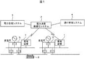
図1は、本発明に係る電力消費最適化システムを含む電気鉄道監視制御システムの構成例を示す図である。図1に示すように、電気鉄道監視制御システムは、蓄電装置1と、電力消費最適化システム2と、電力管理システム3と、運行管理システム4と、変電所5とを有して構成されている。蓄電装置1および変電所5は、車両6の運行範囲に応じて所定の間隔で複数設けられている。
FIG. 1 is a diagram showing a configuration example of an electric railway monitoring and control system including a power consumption optimization system according to the present invention. As shown in FIG. 1, the electric railway monitoring and control system includes a
蓄電装置1は、車両6に供給される電力の蓄電を制御する装置である。蓄電装置1は、電力消費最適化システム2によって電力の消費量が予測された場合、その予測に従って供給すべき電力量を制御する。例えば、電力消費最適化システム2によって現在の消費電力がピークを迎えていると判定された場合にはそれまで蓄積された電力を放出し、現在の消費電力がピークを迎えていないと判定された場合には電力を蓄積する。具体的な処理の内容については、フローチャートを用いて後述する。
The
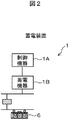
図2は、蓄電装置1の構成例を示す図である。図2に示すように、蓄電装置1は、制御機器1と、蓄電機器2とを有して構成されている。制御機器1は、電力最適化システム2からの指令を受けて、蓄電機器2に対する電力の蓄電を制御する装置である。具体的には後述するが、蓄電機器2は、制御機器1から蓄電モードへの切替指示を受けた場合には電力を内部に蓄え、制御機器1から放電モードへの切替指示を受けた場合には電力を外部に放出する。
FIG. 2 is a diagram illustrating a configuration example of the
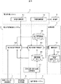
電力消費最適化システム2は、車両6の運行実績や様々な周辺環境の変化によって使用される電力量を予測し、蓄電機器2に対する電力の蓄電制御を最適化するシステムである。図3は、電気鉄道監視制御システムの主要部の構成例を示す図である。図3に示すように、電力最適化システム2は、列車位置・運行実績取得装置21と、電力供給予測装置22と、電力消費予測装置23と、電力管理実績データベース24と、運転実績データベース25とを有して構成されている。
The power
列車位置・運行実績取得装置21は、運行管理システム4から車両6が実際に運行された際の様々な情報(運行情報)を取得する。運行情報としては、例えば、車両6の運転区間、その運転区間内の駅名、駅間距離、駅間時間、勾配(その路線の区間の勾配)、列車速度、列車種別、列車の型式を示す列車車両特性、編成等の情報を有した運転曲線情報、車両重量、パンタグラフ電圧、力行時および回生時の消費電力、空調消費電力、駅混雑状況等の各情報が含まれている。
The train position / operation
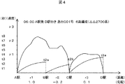
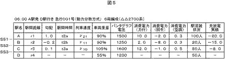
図4は、上述した運転曲線情報の例を示す図である。図4に示す例では、ある日の午前06:00にA駅からD駅まで運行した列車種別が急行001号(6両編成、△△2700系)の運行実績を示している。例えば、A駅からB駅までの駅間距離はr1(km)、その勾配は平均して1.0%の上り勾配であることを示している。また、この列車は、A駅を出発して徐々に加速し、その区間の2/3ほど走行した段階で速度を落として惰行運転しながら通過し、B駅通過までにt2a秒かかっていることを示している。列車位置・運行実績取得装置21は、このような運転曲線情報や、車両重量、パンタグラフ電圧、力行時および回生時の消費電力、空調消費電力、駅混雑状況等の各情報を、運行管理システム4から取得し、その一部の情報を運転実績データベース25に蓄積させる。なお、力行時の消費電力、空調消費電力を合わせて列車消費電力と呼び、回生時の消費電力(発生電力)を回生発生電力と呼ぶ。
FIG. 4 is a diagram illustrating an example of the operation curve information described above. In the example shown in FIG. 4, the train type operated from Express Station A to D Station at 06:00 am on a certain day shows the operation record of Express 001 (6-car train, ΔΔ2700 series). For example, the inter-station distance from station A to station B is r1 (km), and the gradient is 1.0% on the average. In addition, this train should gradually accelerate after leaving A station, pass while coasting at a speed of about 2/3 of that section, and it takes t2a seconds to pass through B station. Is shown. The train position / operation
図5は、運転実績データベース25の例を示す図である。図5に示すように、運転実績データベース25は、駅名と、駅間距離と、駅間区間と、勾配と、列車速度と、車両重量と、パンタグラフ電圧と、消費電力(力行)と、消費電力(回生)と、消費電力(空調)と、駅混雑状況と、放充電実績とを含んでいる。図5では、例えば、A駅からB駅までの駅間距離がr1、駅間時間がt2a、勾配が上り1.0%、列車速度がv21、車両重量が1車両当たり平均して90%の乗客を乗せた場合の重量であることを示している。また、動力車両のパンタグラフの電圧が1500V、力行時の消費電力が10.0kwh、回生発生電力が2.0kwh、空調使用時の消費電力が0.3kwh、A駅改札を通過してホームにいる人の数を示す駅混雑状況は100人であることを示している。これらの各情報は、運行管理システム4から取得されたものである。この他、運転実績データベース25には、蓄電装置1が充放電した実績を示す充放電実績(kwh)を記憶しているが、この内容は、後述するフローチャートに示す処理を行った際に適宜更新される。例えば、A駅とB駅の間に設置された蓄電装置(SS1)は、この列車の運行時には20.0kwhの電力を放出し、B駅とC駅の間に設置された蓄電装置(SS2)は、この列車の運行時には5.0kwhの電力を蓄電したことを示している。このように、運転実績データベース25には、運行管理システム4から取得された列車ごとの運行情報が、時系列に日々蓄積されている。続いて、図3に戻って、電力供給予測装置22について説明する。
FIG. 5 is a diagram illustrating an example of the
電力供給予測装置22は、電力管理システム3によって制御されている変電所5が供給する電力量および自然エネルギー発生装置7が供給する電力量と、環境情報取得装置8が取得した環境情報に応じて変動が予想される電力量とにより、蓄電装置1に供給可能な電力量を予測する装置である。
The power
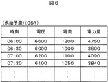
電力供給予測装置22は、電力管理システム3の受電制御装置31から現時点で供給される電圧、電流、電力量の状態を示す各情報(供給電力情報)を取得する。図6は、供給電力情報の例を示す図である。図6に示すように、供給電力情報には、現時点の時刻と、その時刻で供給されている電圧、電流、電力量のそれぞれとが対応付けられている。図6に示す例では、ある日の06:00時点では、蓄電装置SS1は、6600V、1200A、4750kwhの電力供給を受けていることを示している。この例では、30分ごとに供給電力情報を取得している場合について説明しているが、そのタイミングは任意である。なお、供給電力情報は、複数の蓄電装置1のそれぞれから取得される。
The power
また、電力供給予測装置22は、列車位置・運行実績取得装置21および運転実績データベース25にアクセスし、現時点までに発生している回生発生電力を取得し、取得した回生発生電力を供給電力情報に加える。例えば、蓄電装置SS1については、電力供給予測装置22は、列車位置・運行実績取得装置21にアクセスし、現在の時刻がある日の06:00である場合、供給を受けている4750kwhの電力量に、A駅からB駅間の列車「急行001号」の運転によって発生した回生発生電力2.0kwhを加算する。以下では1つの車両6について説明しているが、運行情報が取得された全ての列車について、回生発生電力を加算する。なお、電力供給予測装置22は、未だ列車が運転していない区間に設置されている蓄電装置SS2、SS3については、運転実績データベース25にアクセスし、過去の回生発生電力を、過去の供給電力情報(蓄積供給電力情報。図10において後述する。)に加算して、今後供給可能な電力量を予測する。
Further, the power
また、電力供給予測装置22は、自然エネルギー発生装置7から供給される電力量(自然電力情報)を取得する。自然エネルギー発生装置7は、例えば、太陽光パネルによる発太陽光電設備、あるいは風車による風力発電設備等の再生可能エネルギーを生み出す設備であり、蓄電装置1付近に設置されている。以下では、一例として太陽光発電や風力発電を利用した場合について説明しているが、他の再生可能エネルギーを利用することとしてもよい。
In addition, the power
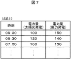
図7は、自然電力情報の例を示す図である。図7に示すように、自然電力情報には、電力が供給されている時点の時刻と、電力量(太陽光発電)と、電力量(風力発電)とが対応付けられている。図7に示す例では、ある日の06:00時点における太陽光発電の電力量が100kwhであり、風力発電の電力量が150kwhであることを示している。自然電力情報についても、供給電力情報と同様に、所定のタイミングで自然エネルギー発生装置7から取得される。なお、図7に示す例では、電力量についてのみ示しているが、図6に示した供給電力情報の場合と同様に、電圧、電流の各情報を含めることも可能である。この場合、より詳細な自然電力情報が得られることとなる。
FIG. 7 is a diagram illustrating an example of natural power information. As shown in FIG. 7, the natural power information is associated with the time when power is supplied, the amount of power (solar power generation), and the amount of power (wind power generation). In the example shown in FIG. 7, the amount of solar power generation at 06:00 on a certain day is 100 kwh, and the amount of wind power generation is 150 kwh. The natural power information is also acquired from the
また、電力供給予測装置22は、環境情報取得装置8から、蓄電装置1周辺の環境情報を取得する。環境情報取得装置8は、環境情報として、例えば、天気予報を行う会社や機関から、その地域の天候や気象に関する情報(天気情報)を収集する装置である。電力供給予測装置22は、環境情報取得装置8にアクセスし、上述した天気情報を取得する。
In addition, the power
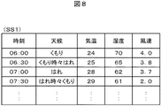
図8は、天気情報の例を示す図である。図8に示すように、天気情報には、天気の観測(または予報)時刻と、その時の天候、気温、湿度、風速のそれぞれとが対応付けられている。図8に示す例では、ある日の06:00時点における天候はくもり、気温が24℃、湿度が70%、風速が4.0mであることを示している。天気情報についても、供給電力情報等と同様に、所定のタイミングで環境情報取得装置8から取得される。
FIG. 8 is a diagram illustrating an example of weather information. As shown in FIG. 8, the weather observation (or forecast) time and the weather, temperature, humidity, and wind speed at that time are associated with the weather information. The example shown in FIG. 8 shows that the weather at 06:00 on one day is cloudy, the temperature is 24 ° C., the humidity is 70%, and the wind speed is 4.0 m. The weather information is also acquired from the environment
電力供給予測装置22は、回生発生電力を加算した供給電力情報、自然電力情報、天気情報を取得すると、これらの電力量を合算してトータルとして蓄電装置1に供給可能な電力量を予測し、その結果(予測電力量)を電力消費予測装置23に出力する。例えば、電力供給予測装置22は、自身が有するタイマ(不図示)によって計時している現在の時刻がその日の07:00時である場合には、取得した天気情報を参照して07:00時点の天候、気温、湿度と、今後予想される07:30時点の天候、気温、湿度とを比較し、取得した自然電力情報に含まれる07:00時点での電力量(太陽光発電)である160kwhから、07:30時点で今後どの程度増減するか予測し、その結果を図6に示した供給電力情報に加算(または減算)する。この場合も、上述したように、電圧、電流の各情報が取得されている場合には、これらについても加算(または減算)することとしてもよい。
When the power
また、電力供給予測装置22は、上述したタイマによって計時される現在の時刻が07:00時である場合、取得した天気情報を参照して07:00時点の風速と、今後予想される07:30時点の風速とを比較し、上述した場合と同様に、取得した自然電力情報に含まれる07:00時点での電力量(風力発電)である130kwhから、07:30時点で今後どの程度増減するか予測し、その結果を図6に示した供給電力情報に加算(または減算)し、その計算後の情報を追加する。この場合も、上述したように、電圧、電流の各情報が取得されている場合には、これらについても加算(または減算)することとしてもよい。その後、電力供給予測装置22は、加算(または減算)して自然電力情報および天気情報を反映させた後の供給電力情報を電力消費装置23に出力する。
In addition, when the current time measured by the above-described timer is 07:00, the power
なお、図6では次の直近のサイクル(現在の時刻が07:00であれば、07:30のタイミング)における電圧、電流、電力量の各情報について予測されている場合について説明しているが、天気情報が取得できる範囲でさらに先のサイクル(例えば、週間予報が取得可能な場合には1週間)を予測することももちろん可能である。この場合、より長期的な消費電力の予測が可能となる。続いて、電力消費予測装置23について説明する。
Note that FIG. 6 illustrates a case where each information of voltage, current, and electric energy is predicted in the next most recent cycle (if the current time is 07:00, the timing of 07:30). Of course, further cycles (for example, one week when a weekly forecast can be obtained) can be predicted within a range in which weather information can be obtained. In this case, longer-term power consumption can be predicted. Next, the power
電力消費予測装置23は、変電所から供給される電力を降圧機や整流器によって変換し、電力供給予測装置22が予測した結果を反映した供給電力情報と、車両6の運行情報とにより、蓄電装置1が消費する電力量を予測し、蓄電装置1に対して車両6に供給する電力量を制御(放電または充電)させる装置である。
The power
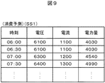
電力消費予測装置23は、電力管理システム3のき電制御装置32が車両6に対して提供している電力量や、その時の電圧、電流の状態を示す各情報(消費電力情報)を取得する。図9は、消費電力情報の例を示す図である。図9に示すように、消費電力情報には、現時点の時刻と、その時刻で消費されている電圧、電流、電力量とが対応付けられている。図9に示す例では、ある日の06:00時点での消費電力情報は、6100V、1100A、4030kwhであることを示している。この例では、30分ごとに消費電力情報を取得している場合について説明しているが、供給電力情報の場合と同様に、そのタイミングは任意であり、複数の蓄電装置1のそれぞれから取得される。
The power
また、電力消費予測装置23は、列車位置・運行実績取得装置21および運転実績データベース25にアクセスし、現時点までに消費している列車消費電力を取得し、取得した列車消費電力を消費電力情報に加える。例えば、蓄電装置SS1については、電力消費予測装置23は、列車位置・運行実績取得装置21にアクセスし、現在の時刻がある日の06:00である場合、消費している4030kwhの電力量に、A駅からB駅間の列車「急行001号」の運転によって消費した列車消費電力10.3kwhを加算する。以下では1つの車両6について説明しているが、運行情報が取得された全ての列車について、列車消費電力を加算する。なお、電力消費予測装置23は、未だ列車が運転していない区間に設置されている蓄電装置SS2、SS3については、運転実績データベース25にアクセスし、過去の列車消費電力を、過去の消費電力情報(蓄積消費電力情報。図11において後述する。)に加算して、今後消費され得る電力量を予測する。
In addition, the power
また、電力消費予測装置23は、上述した供給電力情報や消費電力情報を電力管理実績データベース24に蓄積させる。図10は、電力管理実績データベースが蓄積して記憶する供給電力情報(蓄積供給電力情報)の例を示す図である。図10に示すように、蓄積供給電力情報は、変電所全体の供給電圧、供給電流、供給電力量と、その変電所が管轄するそれぞれの蓄電装置1の供給電圧、供給電流、供給電力量、供給電力量偏差とが対応付けて記憶されている。変電所全体の供給電圧、供給電流、供給電力量は、その変電所が管轄するそれぞれの蓄電装置1における供給電圧、供給電流、供給電力量の合計値である。また、各蓄電装置の供給電圧、供給電流、供給電力量は、図6に示した供給電力情報の電圧、電流、電力量である。なお、供給電力量偏差は、電力供給予測装置22が予測して提供した供給電力情報に示された電力量と実際に供給された電力量(電力量実績値)との差である。例えば、図6に示した例では、06:00時点において供給されている電力量は4750khwであり、この値と、電力供給予測装置22が予測して提供した供給電力情報として記録された電力量との差分が記憶される。この蓄積供給電力情報は、変電所ごとに時系列に記憶される。図10では、ある1日について、蓄電装置SS1〜SS5までを管轄するX変電所を例に、上述した各情報が記憶されていることを示しており、これらの各情報が日々蓄積されている。また、X変電所の標準的な供給電力量は、1つの蓄電装置あたり6000kwhであり、合計で30000kwhであることを示している。
Further, the power
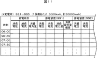
図11は、電力管理実績データベース24が蓄積して記憶する消費電力情報(蓄積消費電力情報)の例を示す図である。図11に示すように、蓄積消費電力情報は、変電所全体の消費電圧、消費電流、消費電力量と、その変電所が管轄するそれぞれの蓄電装置1の消費電圧、消費電流、消費電力量、消費電力量偏差とが対応付けて記憶されている。変電所全体の消費電圧、消費電流、消費電力量は、その変電所が管轄するそれぞれの蓄電装置1における消費電圧、消費電流、消費電力量の合計値である。また、各蓄電装置の消費電圧、消費電流、消費電力量は、図9に示した消費電力情報の電圧、電流、電力量である。なお、消費電力量偏差は、消費電力情報に示された電力量と実際に消費された電力量(消費電力量実績値)との差である。例えば、図9に示した例では、06:00時点において消費されている電力量は4030kwhであり、この値と、電力消費予測装置23が予測した列車消費電力を加算した消費電力情報として記録された電力量との差分が記憶される。この蓄積消費電力情報は、変電所ごとに時系列に記憶される。図11では、蓄積供給電力情報の場合と同様に、ある1日について、蓄電装置SS1〜SS5までを管轄するX変電所を例に、上述した各情報が記憶されていることを示しており、これらの各情報が日々蓄積されている。
FIG. 11 is a diagram illustrating an example of power consumption information (accumulated power consumption information) stored and stored in the power
また、電力管理実績データベース24は、あらかじめ電力を消費すると予想されるイベントやお盆・お正月・ゴールデンウィーク等の時節情報が記録されたカレンダー情報を記憶する。このカレンダー情報には、上述した時節情報および車両6の路線にある駅を乗降するイベントを開催する日程を記憶している。図12は、カレンダー情報の例を示す図である。図12に示すように、カレンダー情報には、休日や祝日が記載された一般的なカレンダーの日付に加え、行われるイベント(市区町村の行事やスポーツ等の鉄道によって参加者や観客が移動して最寄駅に到着(または最寄駅から出発)するようなイベント)に関する情報が記憶されている。図12に示す例では、7月26日には最寄り駅をA駅とした花火大会が予定され、8月29日には最寄り駅をC駅としたナイター野球が行われ、これらの日付におけるA駅やC駅の乗降客数が他のウィークデイよりも多くなることが予想される。また、8月12日の週はお盆を含む1週間であるため、この週には帰省客の増加により、乗客数が他のウィークデイよりも多くなることが予想される。したがって、電力消費予測装置23は、このようなイベントが開催される日付の場合、消費電力が通常よりも多くなると判断し、予想観客数の情報を球場運営団体等から取得したり、運行管理システム4から運行情報の一部として予想帰省客数を取得する。そして、電力消費予測装置23は、取得した予想観客数や予想帰省客数と、運転実績データベース25に記憶されている過去の1日当たりの乗降客数とを比較し、一定の割合を乗じて消費電力情報を算出する。
In addition, the power
続いて、電力消費最適化システム2で行われる蓄電装置1への充放電を制御する処理(蓄電制御処理)について説明する。図13は、電力消費最適化システム2で行われる蓄電制御処理の処理手順を示すフローチャートである。蓄電制御処理は、例えば、列車が蓄電装置を通過したタイミング、1時間ごと等あらかじめ定められたタイミング、蓄電装置1が設置された区間の駅に車両6が到着したタイミング等で処理を開始する。
Then, the process (electric storage control process) which controls charging / discharging to the
図13に示すように、まず、電力消費最適化システム2では、列車位置・運行実績取得装置21が、運行管理システム4から、図4に示した運転曲線情報を含む運行情報を取得する(S1301)。
As shown in FIG. 13, first, in the power
続いて、電力供給予測装置22は、電力管理システム3の受電制御装置31から供給電力情報を取得した後、列車位置・運行実績取得装置21および運転実績データベース25にアクセスし、現時点までに発生している回生発生電力を取得し、取得した回生発生電力を供給電力情報に加えて、今後供給可能な電力量を予測する(ステップS1302)。
Subsequently, the power
例えば、電力供給予測装置22は、列車位置・運行実績取得装置21にアクセスし、現時点での車両の運行によって発生している回生発生電力を、供給電力情報に記録されている電力量に加算するとともに、未だ列車が運転していない区間に設置されている蓄電装置については、運転実績データベース25にアクセスし、過去の回生発生電力を蓄積供給電力情報に加算して、今後供給可能な電力量を予測する。
For example, the power
そして、電力供給予測装置22は、現時点での自然エネルギー発生装置7から自然電力情報を取得するとともに、環境情報取得装置8から蓄電装置1周辺の環境情報を取得し、自然エネルギー発生装置7によって今後供給可能な電力量を予測する(ステップS1303)。
Then, the power
その後、電力供給予測装置22は、ステップS1302およびS1303で予測した供給電力量を合算して電力消費予測装置23に出力するとともに、その内容を蓄積供給電力情報に記録する(ステップS1304)。
Thereafter, the power
電力消費予測装置23は、電力管理システム3のき電制御装置32から消費電力情報を取得した後、列車位置・運行実績取得装置21および運転実績データベース25にアクセスし、現時点までに消費している列車消費電力を取得し、取得した列車消費電力を消費電力情報に加えて、今後消費される電力量を予測する(ステップS1305)。
The power
例えば、電力消費予測装置23は、列車位置・運行実績取得装置21にアクセスし、現時点での車両の運行によって消費している列車消費電力を、消費電力情報に記録されている電力量に加算するとともに、未だ列車が運転していない区間に設置されている蓄電装置については、運転実績データベース25にアクセスし、過去の列車消費電力を蓄積消費電力情報に加算して、今後消費される電力量を予測する。
For example, the power
その後、電力消費予測装置23は、ステップS1305で予測した予測電力量を消費電力情報と合算して出力し、蓄積消費電力情報に記録する(ステップS1306)。そして、ステップS1305およびS1306の処理が終了すると、変電所ごとおよび蓄電装置ごとに、図10に示した蓄積供給電力情報および図11に示した蓄積消費電力情報の現時点での最新の情報が生成されることとなる。
After that, the power
電力消費予測装置23は、生成された蓄積供給電力情報および蓄積消費電力情報の電力量を取得し、各蓄電装置におけるこれらの電力量を変電所ごとに加算し、変電所ごとに予測される供給電力量と消費電力量とを集計して蓄積供給電力情報および蓄積消費電力情報に記録し、変電所ごとに予測される消費電力量の推移を検証するための消費予測推移グラフまたは変電所ごとに予測される供給電力量の推移を検証するための供給予測推移グラフを生成する(ステップS1307)。
The power
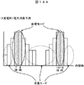
図14Aは、消費電力推移グラフの例を示す図である。図14Aに示すように、電力消費予測装置23は、縦軸を消費される電力量、横軸を時間として、消費電力量の時間毎の推移をグラフ状にした消費電力推移グラフを生成する。図14Aでは、蓄電装置SS1〜SS5までの蓄電装置を管轄する変電所Xの消費電力推移グラフを示しており、現時点の時刻が6時である場合には、その日の7時台〜8時台、および18時台〜19時台に、消費電力のピークを迎えると判断する。
FIG. 14A is a diagram illustrating an example of a power consumption transition graph. As illustrated in FIG. 14A, the power
また、電力消費予測装置23は、図14Bに示すように、消費電力推移グラフと同様に、縦軸を供給される電力量、横軸を時間として、供給電力量の時間毎の推移をグラフ状にした供給電力推移グラフを生成する。図14Bでは、蓄電装置SS1〜SS5までの蓄電装置を管轄する変電所Xの供給電力推移グラフを示している。なお、以下では、消費電力推移グラフを参照して蓄電装置1に対する充放電の制御を行うこととしているが、例えば、供給電力推移グラフと消費電力推移グラフとを比較して、両者の同じ時間帯における差分(偏差)を求め、その偏差がプラスとなる場合には消費よりも供給が多く、偏差がマイナスとなる場合には供給よりも消費が多いと判断し、マイナスとなった偏差が最も大きい時間帯を消費電力のピーク時間帯であると判定することとしてもよい。この場合、供給される電力を考慮して消費電力のピーク時間帯を判定することができる。
Further, as shown in FIG. 14B, the power
そして、電力消費予測装置23は、現在の時刻が消費電力推移グラフから消費電力のピーク時間帯であるか否かを判定し(ステップS1308)、現在の時刻が消費電力のピーク時間帯でないと判定した場合(ステップS1308;No)、その変電所が管轄する各蓄電装置を充電モードに設定するように蓄電装置1に指示をし、蓄電装置1の制御機器1Aは、蓄電機器1Bへの充電を開始する(ステップS1309)。
Then, the power
一方、電力消費予測装置23は、現在の時刻が消費電力のピーク時間帯であると判定した場合(ステップS1308;Yes)、その変電所が管轄する各蓄電装置を放電モードに設定するように蓄電装置1に指示をし、蓄電装置1の制御機器1Aは、蓄電機器1Bからの放電を開始する(ステップS1310)。
On the other hand, when the power
例えば、ステップS1308において消費電力のピーク時間帯である7時台、8時台には、制御パラメータにより蓄電装置1を充電モードにさせる一方、消費電力のピーク時間帯でない7時台、8時台以外の時間帯には、制御パラメータにより蓄電装置1を放電モードにさせる。
For example, in step S1308, at the 7 o'clock and 8 o'clock periods that are the peak time periods of power consumption, the
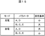
図15は、蓄電装置の制御機器1A内部のメモリ等の記憶部(不図示)に記憶される制御パラメータテーブルの例を示す図である。図15に示すように、制御パラメータテーブルは、蓄電装置の充放電状態を示すモードと、そのモードで蓄電装置を充放電させるためのパラメータと、そのパラメータをどのように制御させるかを示す設定基準とが対応付けて記憶されている。パラメータとしては、蓄電させるための電圧に関するパラメータ(A)、充電率に関するパラメータ(B)、蓄電装置の充電量に関するパラメータ(C)、蓄電装置の放電量に関するパラメータ(D)、蓄電装置の充放電稼働時間に関するパラメータ(E)がある。パラメータは、直線、屈曲線、曲線で設定することが出来る。
FIG. 15 is a diagram illustrating an example of a control parameter table stored in a storage unit (not shown) such as a memory inside the
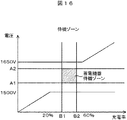
また、電力消費装置23は、内部のメモリ等の記憶部(不図示)に、各蓄電装置1の充放電制御における標準的(デフォルト)な電圧と充電率の設定範囲を示す設定待機グラフを記憶している。図16は、待機設定グラフの例を示す図である。図16に示すように、待機設定グラフは、縦軸を蓄電装置1に充電するための電圧、横軸に蓄電装置1の充電率を設け、蓄電装置1の標準的な設定範囲を表している。図16では、蓄電装置1の待機電圧はA1〜A2であって、充電率がB1〜B2の間が蓄電装置の標準的な設定範囲とされ、この範囲が蓄電機器1の待機ゾーンとして定められていることがわかる。電力消費装置23は、特に指示のない限り、蓄電装置1に入力される電圧がA1を下回れば放電し、A2を上回れば充電されるように常に制御している。
In addition, the
電力消費装置23は、消費電力のピーク時間帯以外の時間帯には、制御パラメータテーブルの充電モードを参照し、各蓄電装置1の設定待機グラフに示されている待機ゾーンが、充電率が大きい方向に移動するように、なるべく早く蓄電させるためにパラメータA(A1、A2)を小さくして待機電圧を下げ、パラメータB(B1、B2)を大きくして充電率を上げる。
The
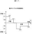
また、電力消費装置23は、上述した不図示の記憶部に、どの程度の時間で蓄電装置を充放電させるかを示す稼働制約グラフを記憶している。図17は、稼働制約グラフの例を示す図である。図17に示すように、稼働制約グラフは、縦軸に充電量(または放電量)の大きさと、横軸に充放電させる時間を設け、蓄電装置にどの程度の時間をかけて充放電させるかが定められている。
In addition, the
電力消費装置23は、消費電力のピーク時間帯以外の時間帯には、制御パラメータテーブルの充電モードを参照し、各蓄電装置1の稼働制約グラフに示されているパラメータDを小さくして放電量を抑えるとともに、パラメータCを大きくして充電量を上げ、かつパラメータEを長くしてより多く充電させる。
The
一方、電力消費装置23は、消費電力のピーク時間帯には、制御パラメータテーブルの放電モードを参照し、上述した各蓄電装置1の設定待機グラフに示されている待機ゾーンが、充電率が小さい方向に移動するように、なるべく早く放電させるためにパラメータA(A1、A2)を大きくして待機電圧を上げ、パラメータB(B1、B2)を小さくして充電率を下げる。さらに、電力消費装置23は、制御パラメータテーブルの放電モードを参照し、上述した各蓄電装置1の稼働制約グラフに示されているパラメータCを小さくして充電量を抑えるとともに、パラメータDを大きくして放電量を上げ、かつパラメータEを短くしてより早く放電させる。このようなパラメータにより充放電を制御することにより、蓄電装置に対する充放電の様々なパターンを設定することができ、充放電の指示を柔軟に行うことができる。
On the other hand, the
このようにして、電力消費装置23からの指示にしたがって蓄電装置1が充放電を行うと、その結果を運転実績データベース25に出力する(ステップS1311)。例えば、蓄電装置1の制御機器1Aは、蓄電機器1Bへの充電量または蓄電機器1Bからの放電量を、充放電実績として運転実績データベース25に記憶させる。
In this way, when the
このように、蓄電装置1と、変電所5からの供給電力を受けた列車への提供電力を管理する電力管理システム3とに接続され、蓄電装置1の充放電を制御する電力消費最適化システム2において、列車位置・運行実績取得装置21が、車両6の運行時に消費した電力である列車消費電力を含む列車6が運行された際の運行情報を、列車6の運行を管理する運行管理システム4から取得し、電力管理実績データベース24が、列車消費電力を含めた消費電力を車両6ごとおよび蓄電装置1ごとに履歴保持し、運転実績データベース25が、運行情報と蓄電装置1による充放電の結果とを対応付けた運行実績情報を車両6ごとに履歴保持し、電力消費予測装置23が、現在の消費電力と、電力管理実績データベース24が記憶する過去の消費電力と、現在の車両6の運行情報と、運転実績データベース25が記憶する運行実績情報とに基づいて、蓄電装置1における今後の消費電力のピーク時間帯を予測し、ピーク時間帯には蓄電装置1に対して放電を指示し、ピーク時間帯以外の時間帯には蓄電装置1に対して充電を指示し、蓄電装置1が、電力消費予測装置23からの充放電の指示に従って電力を充放電し、充放電の結果を運転実績データベース25に記憶させる。
In this way, the power consumption optimization system that controls charging / discharging of the
また、電力管理システム3は供給電力を管理し、電力消費最適化システム2は、列車位置・運行実績取得装置21が、車両6の運行時に発生させた列車発生電力を含む運行情報を運行管理システム4から取得し、電力管理実績データベース24は、列車発生電力を含めた供給電力を車両6ごとおよび蓄電装置1ごとに履歴保持し、電力供給予測装置22が、現在の供給電力と、電力管理実績データベース24が記憶する過去の供給電力と、現在の車両6の運行情報と、運転実績データベース25が記憶する運行実績情報とに基づいて、蓄電装置1に対する今後の供給電力を予測し、供給電力の予測結果を電力消費予測装置23に出力し、電力消費予測装置23は、供給電力の予測結果と消費電力の予測結果とを比較し、供給電力よりも消費電力が最も大きい時間帯を消費電力のピーク時間帯であると判定する。
In addition, the
このような処理を行うことにより、蓄電装置に対して電力を適切に蓄電させることが可能となる。例えば、消費電力量を予測することにより電力配分を最適化するよう蓄電装置の充放電を制御し、電力消費のピークカットを実現することで契約電力量と電力供給設備の低減、電力消費量低減、蓄電池の長寿化と効率的なピークカットの両立が可能となる。また、電気鉄道監視制御システムの系統全体として、消費電力の予測と供給電可能な電力を予測し、蓄電装置の特性を状況に応じて放電モードと充電モードに制御することで、安価な電力を活用することや省エネルギーな運転や消費電力ピークカットを実現することができる。 By performing such processing, it is possible to appropriately store power in the power storage device. For example, by controlling the charging / discharging of power storage devices to optimize power distribution by predicting power consumption and realizing peak cuts in power consumption, contract power consumption and power supply facilities can be reduced, and power consumption can be reduced. Thus, it is possible to achieve both long life of the storage battery and efficient peak cut. Moreover, the electric railway monitoring and control system as a whole predicts the power consumption and the power that can be supplied, and controls the characteristics of the power storage device to the discharge mode and the charge mode according to the situation. Utilization, energy-saving operation and power consumption peak cut can be realized.
上述した実施例では、ステップS1307において消費電力推移グラフおよび供給電力推移グラフを生成し、消費電力のピーク時間帯を判定することとしたが、例えば、過去のグラフの傾向から、ある特定の時間帯(例えば、朝夕のラッシュ時間帯など)に消費電力のピークが生じる可能性が高い場合には、あらかじめその時間帯における蓄電装置1の制御を放電に設定し、必ずその時間帯には放電させることとしてもよい。この場合、ピーク時間帯を特定する処理を行わないため、より速やかに放電の指示を行うことができる。
In the above-described embodiment, the power consumption transition graph and the supply power transition graph are generated in step S1307 and the peak time zone of power consumption is determined. For example, from a past graph trend, a specific time zone is determined. When there is a high possibility that a peak of power consumption will occur during the morning and evening rush hours, for example, the control of the
さらに、消費電力のピークの時間帯を蓄積して不図示の記憶部に記憶しておき、電力消費予測装置23は、その記憶部に蓄積されている時間帯の統計を取得し、取得した統計により現在のピーク時間帯を定めることとしてもよい。例えば、電力消費予測装置23は、最も消費電力がピークとなっている時間帯を迎えている頻度が高い時間帯を判定し、その時間帯をピーク時間帯として定める。この場合、より現状の運行実績を反映した状態でピーク時間帯を定めることができる。
Further, the power consumption peak time zone is accumulated and stored in a storage unit (not shown), and the power
また、電力消費予測装置23は、ステップS1307において生成した消費電力推移グラフおよび供給電力推移グラフを都度蓄積して上述した記憶部に記憶しておき、ステップS1307で生成した消費電力推移グラフおよび供給電力推移グラフを過去のこれらのグラフと比較して最も近似するパターンのグラフを特定し、消費電力のピーク時間帯を定めたり、特定したグラフが得られた際に行っていた充放電の指示と同様の充放電指示をすることも可能である。上述した場合と同様に、ピーク時間帯を特定する処理を行わないため、より速やかに放電の指示を行うことができる。
Further, the power
また、図5に示した運転実績データベース25では、駅間距離や勾配が記憶されているが、これらの路線条件や、乗客数(車両重量)、駅の混雑状況を加味して充放電させる電力量を制御することとしてもよい。例えば、電力消費予測装置23は、勾配がプラスの場合(すなわち上り勾配)であって、一定の勾配以上の場合の位置にある蓄電装置には、上述した消費電力推移グラフによって示された消費電力量は、他の位置にある蓄電装置(例えば、勾配がゼロの位置にある蓄電装置)に比べて、力行による列車消費電力が高くなると判断し、予測値よりも大きい値で消費電力を予測したり、これとは逆に勾配がマイナスの場合(すなわち下り勾配)であって、一定の勾配以下の場合の位置にある蓄電装置には、上述した消費電力推移グラフによって示された消費電力量は、他の位置にある蓄電装置(例えば、勾配がゼロの位置にある蓄電装置)に比べて、回生発生電力が高くなると判断し、予測値よりも小さい値で消費電力を予測することも可能である。
In addition, although the inter-station distance and the gradient are stored in the
また、車両重量が一定数以上の場合には、乗車率が高く、力行時の列車消費電力や回生発生電力の値がより大きくなると判断し、それらの値に一定の割合を乗じて(例えば、乗車率が105%である場合には、予測した消費電力や供給電力の値に1.05を乗じて)消費電力や供給電力を求めることとしてもよい。さらに、乗客数が多い場合には空調による消費電力も大きくなると考えられるため、この場合も一定の割合を乗じて消費電力や供給電力を求めたり、駅の混雑状況が一定数以上の場合には、今後乗車すると予想される乗客数が多いと判断し、この場合も一定の割合を乗じて消費電力や供給電力を求めることとしてもよい。この場合、より詳細に今後の列車消費電力や回生発生電力を予測することができる。 In addition, when the vehicle weight is a certain number or more, it is determined that the boarding rate is high, and that the value of train power consumption and regeneration generated power during power running is larger, and multiplying those values by a certain ratio (for example, When the boarding rate is 105%, the power consumption and the power supply may be obtained by multiplying the predicted power consumption and the power supply by 1.05. Furthermore, it is considered that the power consumption by air conditioning will increase when the number of passengers is large, so in this case as well, the power consumption and supply power are calculated by multiplying a certain ratio, or when the station congestion is more than a certain number It is also possible to determine that there are a large number of passengers expected to board in the future, and in this case as well, the power consumption and the power supply may be obtained by multiplying a certain percentage. In this case, future train power consumption and regenerative power generation can be predicted in more detail.
また、電力消費予測装置23は、運転実績データベース25が記憶する過去の列車の運行実績情報を参照し、消費電力を予測した際に、その後運行されると予測される列車の本数を判別し、その本数が一定数以下となる場合には蓄電装置1に充電を指示してスタンバイ状態にさせ、その本数が一定数よりも多い場合には蓄電装置1に放電を指示することとしてもよい。この場合、その時点での消費予測を行わないので、より速やかに充放電の指示を行うことができる。
In addition, the power
また、電力消費予測装置23は、蓄電装置1との接続が正常に行えない場合には、電力消費最適化システムの異常であると判断し、その時点の蓄電装置1の電圧および充電率の設定範囲を待機ゾーンの設定範囲に戻すこととしてもよい。この場合、異常が発生した場合でも常に安全な状態で蓄電装置の充放電を制御することができる。
In addition, when the connection with the
なお、本発明は上記した実施例に限定されるものではなく、様々な変形例が含まれる。例えば、上記した実施例は本発明を分かりやすく説明するために詳細に説明したものであり、必ずしも説明した全ての構成を備えるものに限定されるものではない。また、ある実施例の構成の一部を他の実施例の構成に置き換えることが可能であり、また、ある実施例の構成に他の実施例の構成を加えることも可能である。また、各実施例の構成の一部について、他の構成の追加・削除・置換をすることが可能である。 In addition, this invention is not limited to an above-described Example, Various modifications are included. For example, the above-described embodiments have been described in detail for easy understanding of the present invention, and are not necessarily limited to those having all the configurations described. Further, a part of the configuration of one embodiment can be replaced with the configuration of another embodiment, and the configuration of another embodiment can be added to the configuration of one embodiment. Further, it is possible to add, delete, and replace other configurations for a part of the configuration of each embodiment.
1 蓄電装置
1A 制御機器
1B 蓄電機器
2 電力消費最適化システム
21 列車位置・運行実績取得装置
22 電力供給予測装置
23 電力消費予測装置
24 電力管理実績データベース
25 運転実績データベース
3 電力管理システム
31 受電制御装置
32 き電制御装置
4 運行管理システム
5 変電所
7 自然エネルギー発生装置
8 環境情報取得装置。
DESCRIPTION OF
Claims (14)
前記列車の運行時に消費した電力である列車消費電力を含む前記列車が運行された際の運行情報を、前記列車の運行を管理する運行管理システムから取得する取得部と、
前記列車消費電力を含めた前記提供電力を前記列車ごとおよび前記蓄電装置ごとに履歴保持する電力管理記憶部と、
前記運行情報と前記蓄電装置による充放電の結果とを対応付けた運行実績情報を前記列車ごとに履歴保持する運行実績記憶部と、
現在の前記提供電力と、前記電力管理記憶部が記憶する過去の前記提供電力と、現在の前記列車の運行情報と、前記運行実績記憶部が記憶する前記運行実績情報とに基づいて、前記蓄電装置における今後の提供電力のピーク時間帯を予測し、前記ピーク時間帯には前記蓄電装置に対して放電を指示し、前記ピーク時間帯以外の時間帯には前記蓄電装置に対して充電を指示する消費予測部と、
前記消費予測部からの充放電の指示に従って電力を充放電し、前記充放電の結果を前記運行実績部に記憶させる前記蓄電装置と、
を備えることを特徴とする電力消費最適化システム。 A power consumption optimization system connected to a power storage device and a power management system that manages power provided to a train that has received power supplied from a substation, and controls charge / discharge of the power storage device,
An acquisition unit that acquires operation information when the train is operated including train power consumption that is electric power consumed during operation of the train from an operation management system that manages the operation of the train;
A power management storage unit for holding the provided power including the train power consumption for each train and each power storage device;
An operation record storage unit that maintains operation record information that associates the operation information with the result of charging and discharging by the power storage device for each train;
Based on the current provided power, the past provided power stored in the power management storage unit, the current operation information of the train, and the operation result information stored in the operation result storage unit, the power storage Predicts the peak time zone of future power supply in the device, instructs the power storage device to discharge during the peak time zone, and instructs the power storage device to charge during a time zone other than the peak time zone A consumption forecasting unit,
The power storage device that charges and discharges electric power according to a charge / discharge instruction from the consumption prediction unit, and stores the charge / discharge result in the operation result unit,
A power consumption optimizing system comprising:
前記電力消費最適化システムは、
前記取得部が、前記列車の運行時に発生させた列車発生電力を含む前記運行情報を前記運行管理システムから取得し、
前記電力管理記憶部は、前記列車発生電力を含めた前記供給電力を前記列車ごとおよび前記蓄電装置ごとに履歴保持し、
現在の前記供給電力と、前記電力管理記憶部が記憶する過去の前記供給電力と、現在の前記列車の運行情報と、前記運行実績記憶部が記憶する前記運行実績情報とに基づいて、前記蓄電装置に対する今後の供給電力を予測し、前記供給電力の予測結果を前記消費予測部に出力する供給予測部をさらに備え、
前記消費予測部は、前記供給電力の予測結果と前記提供電力の予測結果とを比較し、前記供給電力よりも前記提供電力が最も大きい時間帯を提供電力のピーク時間帯であると判定する、
ことを特徴とする請求項1に記載の電力消費最適化システム。 The power management system manages the supply power;
The power consumption optimization system is:
The acquisition unit acquires the operation information including train generated power generated during operation of the train from the operation management system,
The power management storage unit holds the history of the supplied power including the train generated power for each train and each power storage device,
Based on the current supply power, the past supply power stored in the power management storage unit, the current train operation information, and the operation result information stored in the operation result storage unit, the power storage Further comprising a supply prediction unit that predicts future supply power to the device and outputs a prediction result of the supply power to the consumption prediction unit;
The consumption prediction unit compares the prediction result of the supplied power with the prediction result of the provided power, and determines that the time zone in which the provided power is the largest than the supplied power is the peak time zone of the provided power.
The power consumption optimization system according to claim 1.
ことを特徴とする請求項1または2に記載の電力消費最適化システム。 When the rush hour of the train is predetermined as the peak time zone, the consumption prediction unit instructs the power storage device to discharge during the rush hour time zone, and in a time zone other than the rush hour time zone Instructing the power storage device to charge,
The power consumption optimization system according to claim 1 or 2.
前記消費予測部は、蓄積されている過去の前記推移グラフに示されている提供電力の推移の統計を取得し、取得した統計に基づいて、前記ピーク時間帯を定める、
ことを特徴とする請求項3に記載の電力消費最適化システム。 A peak storage unit for accumulating and storing a transition graph indicating a transition of provided power including the peak time zone predicted by the consumption prediction unit;
The consumption prediction unit obtains the statistics of the provided power transition shown in the accumulated past transition graph, and determines the peak time zone based on the obtained statistics.
The power consumption optimization system according to claim 3.
前記消費予測部は、前記ピーク時間帯には、前記電圧を低くするとともに前記充電率を上げるパラメータを選択して前記設定範囲を変更し、前記ピーク時間帯以外の時間帯には、前記電圧を高くするとともに前記充電率を下げるパラメータを選択して前記設定範囲を変更する、
ことを特徴とする請求項1〜4のいずれか1項に記載の電力消費最適化システム。 The power consumption optimization system includes setting standby information indicating a setting range of a standard voltage and a charging rate in charge / discharge control of the power storage device, a parameter for charging / discharging the power storage device, and a setting criterion for the parameter A standby information storage unit that stores a control parameter table in which
The consumption prediction unit changes the setting range by selecting a parameter that lowers the voltage and increases the charging rate in the peak time zone, and changes the voltage in a time zone other than the peak time zone. Change the setting range by selecting a parameter to increase the charging rate and increase the charging rate,
The power consumption optimization system according to any one of claims 1 to 4, wherein
ことを特徴とする請求項4または5に記載の電力消費最適化システム。 When the consumption prediction unit predicts the peak time zone of the provided power, the transition graph including the predicted peak time zone is compared with the transition graph accumulated in the past, and the closest transition graph is specified. And charge / discharge instructions similar to the charge / discharge instructions performed when the specified transition graph was obtained,
The power consumption optimization system according to claim 4 or 5, wherein
前記消費予測部は、前記車両重量が一定数以上の場合には、前記列車の乗客数が多いと判断し、予測した前記提供電力に一定の割合を乗じた値を予測値とする、
ことを特徴とする請求項1〜6のいずれか1項に記載の電力消費最適化システム。 The operation information further includes the vehicle weight of the train,
When the vehicle weight is a certain number or more, the consumption prediction unit determines that the number of passengers on the train is large, and uses a value obtained by multiplying the predicted power supply by a certain ratio as a predicted value.
The power consumption optimizing system according to any one of claims 1 to 6.
前記消費予測部は、前記勾配が一定数以上の場合には、前記列車の力行時の消費電力が多いと判断し、予測した前記提供電力に一定の割合を乗じた値を予測値とする、
ことを特徴とする請求項1〜7のいずれか1項に記載の電力消費最適化システム。 The operation information further includes the slope of the route,
When the slope is equal to or greater than a certain number, the consumption prediction unit determines that the power consumption during powering of the train is large, and uses a value obtained by multiplying the predicted provided power by a certain ratio as a predicted value.
The power consumption optimization system according to any one of claims 1 to 7, wherein
前記消費予測部は、前記混雑状況の値が一定数以上の場合には、今後乗車すると予想される乗客数が多いと判断し、予測した前記提供電力に一定の割合を乗じた値を予測値とする、
ことを特徴とする請求項1〜8のいずれか1項に記載の電力消費最適化システム。 The operation information further includes the congestion status of the station,
When the value of the congestion state is a predetermined number or more, the consumption prediction unit determines that there are a large number of passengers expected to board in the future, and predicts a value obtained by multiplying the predicted supplied power by a certain ratio. And
The power consumption optimization system according to any one of claims 1 to 8, wherein
前記消費予測部は、前記カレンダーに示された時節情報および前記日程の運行情報が取得された場合には、前記列車の乗客数が多いと判断し、予測した前記提供電力に一定の割合を乗じた値を予測値とする、
ことを特徴とする請求項1〜9のいずれか1項に記載の電力消費最適化システム。 The power management storage unit further stores time information and calendar information for storing a schedule to hold an event for getting on and off the station on the train route,
The consumption prediction unit determines that the number of passengers in the train is large when the time information shown on the calendar and the schedule operation information are acquired, and multiplies the predicted power supply by a certain ratio. The predicted value as the predicted value,
The power consumption optimization system according to any one of claims 1 to 9, wherein
前記供給予測部は、前記自然電力発生装置が発生させた自然電力を取得し、
前記電力管理記憶部は、前記自然電力および前記列車発生電力を含めた前記供給電力を前記列車ごとおよび前記蓄電装置ごとに履歴保持し、
前記供給予測部は、前記自然電力および前記列車発生電力を含めた今後の前記供給電力を予測し、前記供給電力の予測結果を前記消費予測部に出力する、
ことを特徴とする請求項2〜10のいずれか1項に記載の電力消費最適化システム。 The power consumption optimization system is connected to a natural power generation device that generates renewable energy,
The supply prediction unit acquires the natural power generated by the natural power generation device,
The power management storage unit maintains a history of the supplied power including the natural power and the train generated power for each train and each power storage device,
The supply prediction unit predicts the future supply power including the natural power and the train generation power, and outputs a prediction result of the supply power to the consumption prediction unit.
The power consumption optimization system according to any one of claims 2 to 10, wherein
ことを特徴とする請求項1〜11のいずれか1項に記載の電力消費最適化システム。 The supply prediction unit refers to the past train operation record information stored in the operation record storage unit, determines the number of trains predicted to be operated thereafter when the supply power is predicted, and the number If the number is less than a certain number, the power storage device is instructed to charge, and if the number is greater than a certain number, the power storage device is instructed to discharge.
The power consumption optimization system according to any one of claims 1 to 11, wherein
ことを特徴とする請求項5〜12のいずれか1項に記載の電力消費最適化システム。 When the connection with the power storage device cannot be normally performed, the consumption prediction unit determines that the power consumption optimization system is abnormal, and the setting range at that time is the range indicated in the setting standby information Back to
The power consumption optimization system according to any one of claims 5 to 12,
前記列車の運行時に消費した電力である列車消費電力を含む前記列車が運行された際の運行情報を、前記列車の運行を管理する運行管理システムから取得する取得ステップと、
現在の前記提供電力と、前記列車消費電力を含めた前記提供電力を前記列車ごとおよび前記蓄電装置ごとに履歴保持する電力管理記憶部が記憶する過去の前記提供電力と、現在の前記列車の運行情報と、前記運行情報と前記蓄電装置による充放電の結果とを対応付けた運行実績情報を前記列車ごとに履歴保持する運行実績記憶部が記憶する前記運行実績情報とに基づいて、前記蓄電装置における今後の提供電力のピーク時間帯を予測する予測ステップと、
前記ピーク時間帯には前記蓄電装置に対して放電を指示し、前記ピーク時間帯以外の時間帯には前記蓄電装置に対して充電を指示する指示ステップと、
前記消費予測部からの充放電の指示に従って電力を充放電し、前記充放電の結果を前記運行実績部に記憶させる充放電ステップと、
を含むことを特徴とする電力提供制御方法。 A power provision control method that is connected to a power storage device and a power management system that manages power provided to a train that has received power supplied from a substation, and that is performed in a power consumption optimization system that controls charging and discharging of the power storage device Because
An acquisition step of acquiring operation information when the train including the train power consumption, which is power consumed when the train is operated, from an operation management system that manages the operation of the train;
The current provided power, the past provided power stored in a power management storage unit that stores the provided power including the train consumed power for each train and each power storage device, and the current operation of the train The power storage device based on the operation result information stored in the operation result storage unit that retains history for each train, the operation result information that associates the information with the operation information and the result of charging and discharging by the power storage device. A prediction step for predicting the peak hours of future power supply in
Instructing to discharge the power storage device during the peak time period, and instructing charging to the power storage device during a time period other than the peak time period;
A charge / discharge step of charging / discharging electric power according to a charge / discharge instruction from the consumption prediction unit, and storing the result of the charge / discharge in the operation result unit,
A power supply control method comprising:
Priority Applications (1)
| Application Number | Priority Date | Filing Date | Title |
|---|---|---|---|
| JP2012191427A JP6009281B2 (en) | 2012-08-31 | 2012-08-31 | Power consumption optimization system and power supply control method |
Applications Claiming Priority (1)
| Application Number | Priority Date | Filing Date | Title |
|---|---|---|---|
| JP2012191427A JP6009281B2 (en) | 2012-08-31 | 2012-08-31 | Power consumption optimization system and power supply control method |
Publications (2)
| Publication Number | Publication Date |
|---|---|
| JP2014046821A true JP2014046821A (en) | 2014-03-17 |
| JP6009281B2 JP6009281B2 (en) | 2016-10-19 |
Family
ID=50606914
Family Applications (1)
| Application Number | Title | Priority Date | Filing Date |
|---|---|---|---|
| JP2012191427A Active JP6009281B2 (en) | 2012-08-31 | 2012-08-31 | Power consumption optimization system and power supply control method |
Country Status (1)
| Country | Link |
|---|---|
| JP (1) | JP6009281B2 (en) |
Cited By (12)
| Publication number | Priority date | Publication date | Assignee | Title |
|---|---|---|---|---|
| JP2014073014A (en) * | 2012-09-28 | 2014-04-21 | Toshiba Corp | Railway power management equipment |
| US20150165931A1 (en) * | 2012-10-31 | 2015-06-18 | Kabushiki Kaisha Toshiba | Power management apparatus and power management system |
| JP2015134523A (en) * | 2014-01-16 | 2015-07-27 | 株式会社日立製作所 | Electric railroad power control system and method |
| JP2016092886A (en) * | 2014-10-30 | 2016-05-23 | 株式会社日立製作所 | Driving support device and driving support method |
| CN106458239A (en) * | 2014-06-11 | 2017-02-22 | 株式会社东芝 | Information processing device and operation curve generation method |
| KR101776008B1 (en) * | 2015-08-11 | 2017-09-19 | 한국철도기술연구원 | Electric railway vehicle system between stations using a rapid charge system |
| JP2018140699A (en) * | 2017-02-28 | 2018-09-13 | 公益財団法人鉄道総合技術研究所 | Program and operation pattern determination device |
| JP2020132004A (en) * | 2019-02-21 | 2020-08-31 | 公益財団法人鉄道総合技術研究所 | Control method and control device |
| CN115178590A (en) * | 2022-09-07 | 2022-10-14 | 承德建龙特殊钢有限公司 | Seamless steel tube production method |
| CN117200408A (en) * | 2023-11-08 | 2023-12-08 | 广东精冷源建设有限公司 | Energy dynamic storage energy-saving control method and system for variable frequency cabinet |
| WO2026048078A1 (en) * | 2024-09-02 | 2026-03-05 | 三菱電機株式会社 | Power amount prediction device, power amount prediction method, program, and power amount prediction system |
| WO2026074736A1 (en) * | 2024-10-03 | 2026-04-09 | 三菱電機株式会社 | Electric power amount analyzing device, electric power amount analyzing method, program, and electric power amount analyzing system |
Citations (5)
| Publication number | Priority date | Publication date | Assignee | Title |
|---|---|---|---|---|
| JPS6056049B2 (en) * | 1980-09-29 | 1985-12-07 | 日本電池株式会社 | DC busbar response device with fluctuating loads |
| JP2003324808A (en) * | 2002-05-03 | 2003-11-14 | Alstom | Method and system for monitoring and regulating power consumed in transport system |
| JP2005162076A (en) * | 2003-12-04 | 2005-06-23 | Hitachi Ltd | Regenerative power absorption control method and apparatus for electric railway, and control device for power converter |
| US20110307113A1 (en) * | 2010-06-15 | 2011-12-15 | Ajith Kuttannair Kumar | Control assembly and control method for supplying power to electrified rail vehicles |
| JP2012040954A (en) * | 2010-08-19 | 2012-03-01 | Toshiba Corp | System for supplying electric power for electric railroad |
-
2012
- 2012-08-31 JP JP2012191427A patent/JP6009281B2/en active Active
Patent Citations (5)
| Publication number | Priority date | Publication date | Assignee | Title |
|---|---|---|---|---|
| JPS6056049B2 (en) * | 1980-09-29 | 1985-12-07 | 日本電池株式会社 | DC busbar response device with fluctuating loads |
| JP2003324808A (en) * | 2002-05-03 | 2003-11-14 | Alstom | Method and system for monitoring and regulating power consumed in transport system |
| JP2005162076A (en) * | 2003-12-04 | 2005-06-23 | Hitachi Ltd | Regenerative power absorption control method and apparatus for electric railway, and control device for power converter |
| US20110307113A1 (en) * | 2010-06-15 | 2011-12-15 | Ajith Kuttannair Kumar | Control assembly and control method for supplying power to electrified rail vehicles |
| JP2012040954A (en) * | 2010-08-19 | 2012-03-01 | Toshiba Corp | System for supplying electric power for electric railroad |
Cited By (17)
| Publication number | Priority date | Publication date | Assignee | Title |
|---|---|---|---|---|
| US9764649B2 (en) | 2012-09-28 | 2017-09-19 | Kabushiki Kaisha Toshiba | Power management apparatus, power management method and power management program |
| US20140368154A1 (en) * | 2012-09-28 | 2014-12-18 | Kabushiki Kaisha Toshiba | Power management apparatus, power management method and power management program |
| JP2014073014A (en) * | 2012-09-28 | 2014-04-21 | Toshiba Corp | Railway power management equipment |
| US20150165931A1 (en) * | 2012-10-31 | 2015-06-18 | Kabushiki Kaisha Toshiba | Power management apparatus and power management system |
| US9707862B2 (en) * | 2012-10-31 | 2017-07-18 | Kabushiki Kaisha Toshiba | Power management apparatus and power management system |
| JP2015134523A (en) * | 2014-01-16 | 2015-07-27 | 株式会社日立製作所 | Electric railroad power control system and method |
| CN106458239A (en) * | 2014-06-11 | 2017-02-22 | 株式会社东芝 | Information processing device and operation curve generation method |
| JP2016092886A (en) * | 2014-10-30 | 2016-05-23 | 株式会社日立製作所 | Driving support device and driving support method |
| KR101776008B1 (en) * | 2015-08-11 | 2017-09-19 | 한국철도기술연구원 | Electric railway vehicle system between stations using a rapid charge system |
| JP2018140699A (en) * | 2017-02-28 | 2018-09-13 | 公益財団法人鉄道総合技術研究所 | Program and operation pattern determination device |
| JP2020132004A (en) * | 2019-02-21 | 2020-08-31 | 公益財団法人鉄道総合技術研究所 | Control method and control device |
| JP7281297B2 (en) | 2019-02-21 | 2023-05-25 | 公益財団法人鉄道総合技術研究所 | Control method and control device |
| CN115178590A (en) * | 2022-09-07 | 2022-10-14 | 承德建龙特殊钢有限公司 | Seamless steel tube production method |
| CN117200408A (en) * | 2023-11-08 | 2023-12-08 | 广东精冷源建设有限公司 | Energy dynamic storage energy-saving control method and system for variable frequency cabinet |
| CN117200408B (en) * | 2023-11-08 | 2024-03-22 | 广东精冷源建设有限公司 | Energy dynamic storage energy-saving control method and system for variable frequency cabinet |
| WO2026048078A1 (en) * | 2024-09-02 | 2026-03-05 | 三菱電機株式会社 | Power amount prediction device, power amount prediction method, program, and power amount prediction system |
| WO2026074736A1 (en) * | 2024-10-03 | 2026-04-09 | 三菱電機株式会社 | Electric power amount analyzing device, electric power amount analyzing method, program, and electric power amount analyzing system |
Also Published As
| Publication number | Publication date |
|---|---|
| JP6009281B2 (en) | 2016-10-19 |
Similar Documents
| Publication | Publication Date | Title |
|---|---|---|
| JP6009281B2 (en) | Power consumption optimization system and power supply control method | |
| JP6054122B2 (en) | Railway power management equipment | |
| CN107719180B (en) | Multi-source complementary charging method for hybrid parking lot based on flexible charging of electric vehicles | |
| US9682633B2 (en) | Charge control device, battery management device, charge control method, and record medium | |
| CN103078389B (en) | Integrated power system control method and related device with energy storage element | |
| JP5877479B2 (en) | Power management system, power management method, program | |
| KR101478791B1 (en) | Method and System for Power Management | |
| JP5312504B2 (en) | Energy management system | |
| EP3190676B1 (en) | Electricity storage control device | |
| US20150165915A1 (en) | Vehicle charging system | |
| JP2013172488A (en) | Charging power supply unit and charging power supply management device, energy management system, and charging power supply management method | |
| JP2018068076A (en) | Storage battery control system and power supply system | |
| CN104124724A (en) | Charging control apparatus and method thereof | |
| JP2014064449A (en) | Power management device, power management method, and program | |
| CN117794776A (en) | Charging control and scheduling of electric vehicles and related systems and methods | |
| KR20130092707A (en) | System and control method for community energy system | |
| JP2017158356A (en) | Power supply system | |
| JP2021180581A (en) | SOC control device for power storage device | |
| CN119636496A (en) | A new energy vehicle charging management system | |
| Chen et al. | Research on the influence of electric vehicle multi-factor charging load on a regional power grid | |
| JP2013141374A (en) | Electric power supply system for electric railroad | |
| JP6870678B2 (en) | Power storage system | |
| JP2016032950A (en) | Control device | |
| JP5922555B2 (en) | Operation management system | |
| JP6705652B2 (en) | Battery control method |
Legal Events
| Date | Code | Title | Description |
|---|---|---|---|
| A621 | Written request for application examination |
Free format text: JAPANESE INTERMEDIATE CODE: A621 Effective date: 20150518 |
|
| A131 | Notification of reasons for refusal |
Free format text: JAPANESE INTERMEDIATE CODE: A131 Effective date: 20160329 |
|
| A521 | Request for written amendment filed |
Free format text: JAPANESE INTERMEDIATE CODE: A523 Effective date: 20160428 |
|
| A521 | Request for written amendment filed |
Free format text: JAPANESE INTERMEDIATE CODE: A523 Effective date: 20160610 |
|
| A131 | Notification of reasons for refusal |
Free format text: JAPANESE INTERMEDIATE CODE: A131 Effective date: 20160705 |
|
| A521 | Request for written amendment filed |
Free format text: JAPANESE INTERMEDIATE CODE: A523 Effective date: 20160803 |
|
| TRDD | Decision of grant or rejection written | ||
| A01 | Written decision to grant a patent or to grant a registration (utility model) |
Free format text: JAPANESE INTERMEDIATE CODE: A01 Effective date: 20160830 |
|
| A61 | First payment of annual fees (during grant procedure) |
Free format text: JAPANESE INTERMEDIATE CODE: A61 Effective date: 20160914 |
|
| R150 | Certificate of patent or registration of utility model |
Ref document number: 6009281 Country of ref document: JP Free format text: JAPANESE INTERMEDIATE CODE: R150 |