JP2014046826A - Retractable vehicle seat - Google Patents
Retractable vehicle seat Download PDFInfo
- Publication number
- JP2014046826A JP2014046826A JP2012191532A JP2012191532A JP2014046826A JP 2014046826 A JP2014046826 A JP 2014046826A JP 2012191532 A JP2012191532 A JP 2012191532A JP 2012191532 A JP2012191532 A JP 2012191532A JP 2014046826 A JP2014046826 A JP 2014046826A
- Authority
- JP
- Japan
- Prior art keywords
- seat
- vehicle
- engaged
- pin
- hook
- Prior art date
- Legal status (The legal status is an assumption and is not a legal conclusion. Google has not performed a legal analysis and makes no representation as to the accuracy of the status listed.)
- Granted
Links
- 230000007246 mechanism Effects 0.000 description 5
- 238000012217 deletion Methods 0.000 description 1
- 230000037430 deletion Effects 0.000 description 1
- 230000005484 gravity Effects 0.000 description 1
- 230000001105 regulatory effect Effects 0.000 description 1
Images




Landscapes
- Seats For Vehicles (AREA)
Abstract
【課題】シートバック40をシートクッション50上に折り畳み、更にシートクッション50の車両側壁側をヒンジ中心として回動して車両側壁に沿って格納可能とされた格納式車両用シートにおいて、シートを格納位置に保持するためのロック装置を、相対移動するのみで互いの係合面が重合、及び重合解除される2部材によって構成することにより、ロック装置の構成を簡単にして安価に構成する。
【解決手段】シートバック40側に設けられたピン10と、車両側壁B側に設けられた被係合部材20とによってロック装置が構成され、ロック装置のロック時、互いに重合して係合するピン10の鍔部12の裏面、及び被係合部材20のスライドレバー22の内側面のうち後者を、車両後方に移動可能とされ、この移動により、各係合面が互いに重合して係合するロック装置のロック状態と、各係合面が互いに重合せず係合しないロック装置のロック解除状態とが実現される。
【選択図】図6A seat is stored in a retractable vehicle seat that is folded on a seat cushion and further pivoted about a vehicle side wall side of the seat cushion 50 as a hinge center and can be stored along the vehicle side wall. By configuring the lock device for holding in position with two members whose engagement surfaces are overlapped and released only by relative movement, the structure of the lock device is simplified and inexpensively configured.
A lock device is constituted by a pin 10 provided on a seat back 40 side and an engaged member 20 provided on a vehicle side wall B, and overlaps and engages with each other when the lock device is locked. The latter of the rear surface of the flange portion 12 of the pin 10 and the inner surface of the slide lever 22 of the engaged member 20 can be moved rearward of the vehicle. The locked state of the locking device to be engaged and the unlocked state of the locking device in which the engagement surfaces do not overlap with each other are realized.
[Selection] Figure 6
Description
本発明は、シートバックをシートクッション上に折り畳み、更にシートクッションの端部をヒンジ中心として回動して車室内でコンパクトに格納可能とされた格納式車両用シートに関する。 The present invention relates to a retractable vehicle seat in which a seat back is folded on a seat cushion, and further, an end portion of the seat cushion is rotated about a hinge to be compactly stored in a vehicle interior.
上記格納式車両用シートが一部車両で実用化されている。下記特許文献1には、車両側壁に沿って格納可能とされた格納式車両用シートが開示されている。
下記特許文献1の格納式車両用シートでは、格納されたシートを格納位置に保持するためのロック装置を備えている。係るロック装置は、シートバック背面のストライカと車両側壁のラッチ機構とによって構成されている。
The retractable vehicle seat has been put into practical use in some vehicles. Patent Document 1 below discloses a retractable vehicle seat that can be stored along a vehicle side wall.
The retractable vehicle seat disclosed in Patent Document 1 includes a lock device for holding the stored seat in the storage position. Such a locking device includes a striker on the back of the seat back and a latch mechanism on the side wall of the vehicle.
上記特許文献1の格納式車両用シートでは、ロック装置としてストライカと係合するラッチ機構を採用しているが、ラッチ機構は、ロック時には、進入してくるストライカを受け入れて掴み、ロック解除時には、掴んでいたストライカを解放する構成であり、構造が複雑で、高価である問題がある。
このような問題に鑑み本発明の課題は、格納式車両用シートを格納位置に保持するためのロック装置を、相対移動するのみで互いの係合面が重合、及び重合解除される2部材によって構成することにより、ロック装置の構成を簡単にして安価に構成することにある。
The retractable vehicle seat of Patent Document 1 employs a latch mechanism that engages with a striker as a locking device, but the latch mechanism accepts and holds an incoming striker when locked, and when unlocked, The structure is such that the striker that has been held is released, and there is a problem that the structure is complicated and expensive.
In view of such a problem, an object of the present invention is to provide a locking device for holding a retractable vehicle seat in a retracted position by two members whose engagement surfaces are overlapped and released only by relative movement. By configuring, the configuration of the lock device is simplified and inexpensively configured.
本発明の第1発明は、シートバックをシートクッション上に折り畳み、更にシートクッションの端部をヒンジ中心として回動して車室内でコンパクトに格納可能とされた格納式車両用シートであって、前記シートバックとシート格納時に前記シートバックに対応する固定側部材とに設けられ、前記シートの格納位置においてシートを格納位置に保持するロック装置を備え、該ロック装置は、フックと、該フックに係合可能とされた被係合部材とから成り、前記ロック装置のロック時、互いに重合して係合する前記フック及び前記被係合部材の各係合面の一方を、当該面に沿う方向に相対移動可能に構成され、この相対移動により、各係合面が互いに重合して係合する前記ロック装置のロック状態と、各係合面が互いに重合せず係合しない前記ロック装置のロック解除状態とが実現されることを特徴とする。
第1発明によれば、互いに重合して係合するフック及び被係合部材の各係合面の一方を当該面に沿う方向に相対移動することにより、ロック装置のロック状態とロック解除状態とが実現される。そのため、ロック装置の構成を簡単にして安価に構成することができる。
The first invention of the present invention is a retractable vehicle seat that can be compactly stored in the vehicle interior by folding the seat back on the seat cushion and further turning the end of the seat cushion around the hinge. A locking device is provided on the seat back and a fixed side member corresponding to the seat back when the seat is stored, and holds the seat in the storage position at the storage position of the seat, and the locking device includes a hook and a hook. A direction along the surface of one of the hooks and the engaging surfaces of the engaged members that are engaged with each other when the locking device is locked. The locking device is configured such that the engaging surfaces overlap and engage with each other, and the engaging surfaces do not overlap with each other and do not engage with each other. Characterized in that the unlocked state of the click device can be realized.
According to the first aspect of the present invention, the lock device is locked and unlocked by relatively moving one of the engagement surfaces of the hook and the engaged member that are overlapped with each other in the direction along the surface. Is realized. For this reason, the configuration of the lock device can be simplified and inexpensively configured.
本発明の第2発明は、上記第1発明において、前記シートは、シートバックをシートクッション上に折り畳み、更にシートクッションの車両側壁側をヒンジ中心として回動して車両側壁に沿って格納可能とされた格納式車両用シートであり、前記フックはシートバックに、また前記被係合部材は車両側壁にそれぞれ設けられ、前記被係合部材の係合面は、車両前後方向に移動可能とされ、この移動により前記フックの係合面に対して係合、及び係合解除されることを特徴とする。
第2発明によれば、被係合部材の係合面が、車両前後方向に移動されることにより、ロック装置のロック状態とロック解除状態とが実現される。そのため、車両側壁に設けられた被係合部材を車両後方から容易に操作することができ、操作性を良くすることができる。
According to a second aspect of the present invention, in the first aspect, the seat can be stored along the vehicle side wall by folding the seat back onto the seat cushion and further rotating the seat side wall of the seat cushion about the hinge. The hook is provided on a seat back and the engaged member is provided on a side wall of the vehicle, and the engaging surface of the engaged member is movable in the vehicle front-rear direction. In this manner, the hook is engaged with and disengaged from the engaging surface of the hook.
According to the second aspect of the present invention, the locked state and the unlocked state of the locking device are realized by moving the engaging surface of the engaged member in the vehicle front-rear direction. Therefore, the engaged member provided on the vehicle side wall can be easily operated from the rear of the vehicle, and the operability can be improved.
本発明の第3発明は、上記第1又は第2発明において、前記各係合面の一方は、その相対移動の方向に対して傾斜した縁部を有し、前記各係合面の他方を形成するフック又は被係合部材には、前記縁部に当接可能な当接部を備え、前記縁部は、前記当接部が前記係合面の面に沿う方向で互いに離間した2箇所となるように、第1の傾斜線に沿った第1の縁部と、第1の傾斜線に対して交差する第2の傾斜線に沿った第2の縁部とを備えることを特徴とする。
第3発明によれば、両係合面が重合して係合するとき、第1及び第2の縁部を当接部の2箇所に当接させる。その結果、一方の係合面の2つの縁部によって当接部を挟んで保持することができ、フックと被係合部材とをがたつくことなく係合させることができる。
また、2つの傾斜線に沿った縁部によって当接部を挟んで両係合面を係合させることができるため、2つの縁部が当接部から離れるときは両者は大きく離れることができ、フックと被係合部材とを係合させるときの両者の係合のための接近を低い寸法精度で行うことができる。
According to a third aspect of the present invention, in the first or second aspect of the present invention, one of the engagement surfaces has an edge that is inclined with respect to the direction of relative movement, and the other of the engagement surfaces is The hook or member to be formed is provided with an abutting portion that can abut against the edge, and the edge is separated from each other in a direction along the surface of the engaging surface. A first edge along the first slope line and a second edge along the second slope line intersecting the first slope line, To do.
According to the third invention, when both engaging surfaces are overlapped and engaged, the first and second edge portions are brought into contact with the two portions of the contact portion. As a result, the abutting portion can be sandwiched and held by the two edges of the one engaging surface, and the hook and the engaged member can be engaged without rattling.
In addition, since the two engaging surfaces can be engaged with each other with the abutting portion sandwiched by the edge portions along the two inclined lines, when the two edge portions are separated from the abutting portion, both can be separated greatly. When the hook and the member to be engaged are engaged, the approach for engaging the hook and the engaged member can be performed with low dimensional accuracy.
<第1実施形態>
図1〜8によって本発明の第1実施形態を説明する。第1実施形態は、車両の後列右側のシートが車両の右側壁に沿って格納される例を示している。各図において、矢印で示すFは車両前方、Uは車両上方、Rは車両右方を、それぞれ示す。
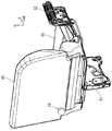
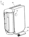
この例において、シートは、シートバック40をシートクッション50上に折り畳み、更にシートクッション50の車両側壁B側のヒンジブラケット52を中心として回動して車両側壁B(本発明の固定側部材に相当する。)に沿って格納可能とされている。図1はシートが着座位置にある状態を示し、図2〜4はシートが格納位置にある状態を示している。図4において、実線で示すシートバック40及びシートクッション50の位置が格納位置であり、二点鎖線で示す格納前の位置から、矢印で示すように、実線で示す格納位置にシートバック40及びシートクッション50が跳ね上げ可能とされている。
シートクッション50の底面には周知のように脚部51が設けられており、脚部51の端部に設けられた一対のラッチ機構が、図4で二点鎖線で示すように、車両フロアFに設けられた一対のストライカ60と係合することにより、シートクッション50が車両フロアFに固定されている。図4で実線で示すように、シートクッション50が跳ね上げられると、脚部51は一対のラッチ機構が設けられた側とは反対側端部をヒンジ中心として回動され、シートクッション50の底面の凹部内に矢印で示すように格納されるように構成されている。
<First Embodiment>
A first embodiment of the present invention will be described with reference to FIGS. 1st Embodiment has shown the example by which the sheet | seat of the back row right side of a vehicle is stored along the right side wall of a vehicle. In each figure, F indicated by an arrow indicates the front of the vehicle, U indicates the upper side of the vehicle, and R indicates the right side of the vehicle.
In this example, the seat folds the seat back 40 on the
As is well known, a
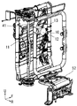
シートバック40の背面には、図1〜3に示されるように、鍔付きのピン10が設けられている。ピン10は、図1のように、シートが着座位置にある状態では、シートバック40の背面の左下部に位置し、シートが格納位置にある状態では、図2、3のように、シートバック40の背面で車両側壁Bに対向する位置にある。
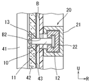
図3、5に示されるように、ピン10は、ピン本体11の先端に鍔部12を一体に備えて成り、ピン本体11は、ブラケット13を介してシートバックフレームを成すパイプ41に溶接にて固定されている。このとき、ピン本体11は、シートバック40のクッションパッド42及びシート表皮43を貫通して、先端部がシート表皮43の表面上に突出するように構成されている。
ピン10は、本発明のフックに相当する。
As shown in FIGS. 1 to 3, a
As shown in FIGS. 3 and 5, the
The
図4に示されるように、シートが格納位置にあるとき、シートバック40の背面に設けられたピン10が対向する車両側壁Bには、ピン10とともにロック装置を成す被係合部材20が設けられている。
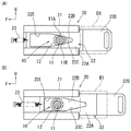
被係合部材20は、図7に示されるように、四角筒の壁面の一部がカットされた形状のレール21と、このレール21の筒内部に摺動自在に挿入されたスライドレバー22とから成り、スライドレバー22は、レール21の筒内部に挿入される四角筒形状の本体部22Aと、この本体部22Aと一体に形成されレール21から突出して形成された操作部22Dとから成る。スライドレバー22の本体部22Aのうち、レール21のカット部に対応する部分には矢印形状の切欠部22Eが形成されており、この切欠部22Eの一部を形成する縁部22B、22Cは、スライドレバー22がレール21内で摺動して移動する方向(車両前後方向)に対して傾斜して配置されている。縁部22Bが成す第1の傾斜線と縁部22Cが成す第2の傾斜線とは互いに交差する関係とされている。
スライドレバー22の本体部22Aの操作部22Dとは反対側にはばね23が取り付けられており、ばね23は車両側壁Bとの間に張設され、スライドレバー22を常時、車両前方へ付勢している。このため、図8(B)に示されるように、車両乗員が操作部22Dを掴んで車両後方側へ引張ると、ばね23の付勢力に抗してスライドレバー22がレール21内で移動して、スライドレバー22の本体部22Aの切欠部22Eを介して本体部22A内にピン10の先端部を受け入れることができるようになる。その後、車両乗員が操作部22Dを掴んでいた手を放すと、ばね23の付勢力によってスライドレバー22の本体部22Aは、図8(A)で示されるように、レール21内で移動して、スライドレバー22の本体部22A内に挿入されているピン10の先端部の第1の当接部11A及び第2の当接部11Bに縁部22B及び22Cが当接することになる。
このようにピン10の2つの当接部11A、11Bに縁部22B、22Cが当接した状態では、スライドレバー22の本体部22Aの内側面とピン10の鍔部12の裏面とが係合面となって係合し、ピン10とスライドレバー22とによって構成されるロック装置がロック状態とされる。これによりシートを格納位置に保持することができる。
図4〜6に示されるように、被係合部材20はスライドレバー22の操作部22Dの先端部を除いて車両側壁B内に埋設されており、スライドレバー22の操作部22Dの先端部は車両側壁Bに形成された貫通孔B1を介して車室内に露出されている。また、車両側壁Bのピン10に対応する位置には貫通孔B2が形成されており、この貫通孔B2を介してピン10がスライドレバー22の本体部22A内に進入可能とされている。
As shown in FIG. 4, when the seat is in the retracted position, an engaged
As shown in FIG. 7, the engaged
A
As described above, when the
As shown in FIGS. 4 to 6, the engaged
以上のようにピン10がシートバック40に設けられ、ピン10が係合する被係合部材20が車両側壁Bに設けられているため、シートバック40及びシートクッション50を車両側壁Bに沿う格納位置としたとき、図4〜6、図8(A)のように、ピン10の鍔部12を含むピン本体11の先端がスライドレバー22の本体部22A内に挿入され、ピン10の鍔部12の裏面とスライドレバー22の本体部22Aの内側面とが係合される。このとき、図8(B)のように、スライドレバー22の操作部22Dを引張り操作しないとピン本体11の先端がスライドレバー22の本体部22A内に進入することができないため、シートを格納位置へ移動しながらスライドレバー22の操作部22Dを引張り操作することになる。ピン本体11の先端がスライドレバー22の本体部22A内に挿入された後は、スライドレバー22の操作部22Dの引張り操作を解除することにより、ばね23の付勢力によりスライドレバー22は、上述のようにピン10の鍔部12の裏面とスライドレバー22の本体部22Aの内側面とが係合された状態となる。
As described above, since the
この状態では、スライドレバー22の本体部22A内に挿入されているピン10の先端部の第1の当接部11A及び第2の当接部11Bに、スライドレバー22の本体部22Aの縁部22B及び22Cがばね23の付勢力を受けて当接している。このため、ピン本体11の先端は縁部22Bと縁部22Cとによって挟まれて保持されることになり、ピン10を被係合部材のスライドレバー22に対してがたつくことなく係合させることができる。
この場合、縁部22B、22Cは、スライドレバー22がレール21内で摺動して移動する方向に対して傾斜して配置され、しかも縁部22Bが成す第1の傾斜線と縁部22Cが成す第2の傾斜線とは互いに交差する関係とされているため、縁部22Bと縁部22Cとが互いに離間した側では大きなスペースを確保することができ、シートバック40側のピン本体11の先端を車両側壁B側のスライドレバー22の本体部22A内に進入させるための両者の位置合せの寸法精度を低くすることができる。
In this state, the edge portion of the
In this case, the
以上のとおり、第1実施形態によれば、ピン10の鍔部12をスライドレバー22の本体部22A内に進入させるに際して、操作部22Dを引張り操作して、その後は操作部22Dの操作を解除すれば、ピン10の鍔部12の裏面に対してスライドレバー22の本体部22Aの内側面を重合して係合させて、ロック装置をロック状態とすることができる。一方、ロック装置をロック解除状態とする際は、ばね23の付勢力に抗してスライドレバー22の操作部22Dを引張り操作すれば良い。このようにロック装置をロック状態とするときも、ロック装置をロック解除状態とするときも、スライドレバー22の操作部22Dを引張り操作するのみで済み、操作を簡略化することができる。また、車両側壁Bに設けられた被係合部材20のスライドレバー22を車両後方から容易に操作することができ、操作性を良くすることができる。
しかも、ピン10の鍔部12の裏面に対してスライドレバー22の本体部22Aの内側面を重合させるか否かにより、ロック装置のロック状態とロック解除状態とが切り換えられ、この切換をスライドレバー22を車両前後方向に移動させる簡単な構成で実現できる。そのため、ロック装置の構成を簡単にして安価に構成することができる。
As described above, according to the first embodiment, when the
Moreover, the lock device can be switched between the locked state and the unlocked state depending on whether or not the inner surface of the
<第2実施形態>
図9によって本発明の第2実施形態を説明する。第2実施形態が上述の第1実施形態に対して特徴とする点は、ピン10をシートバック40の背面上に突出した状態と突出しない状態とに移動可能とし、シートバック40がシートクッション50上に折り畳まれた状態にあるときにピン10が突出状態とされ、シートバック40が乗員着座位置にあるときに非突出状態とされるように構成された点にある。第2実施形態において、その他の点は、第1実施形態と同一であり、同一部分は図示を省略し、図示されている部分でも同一部分には同一符号を付して再度の説明は省略する。
Second Embodiment
A second embodiment of the present invention will be described with reference to FIG. The second embodiment is characterized in that the
図9において、ピン10は、上記第1実施形態の場合と同様にシートバック40の背面に設けられているが、ピン10のピン本体14は、パイプ41に結合されたブラケット44を貫通して配置されている。ピン本体14のシートバック40内側端は、係合片15に結合され、係合片15は、一端がシートバック40のシートフレーム(不図示)に結合されたばね18の他端に結合されている。そのため、ピン本体14は、ばね18によりシートバック40の背面から突出するように付勢されている。このときのピン本体14の突出量は、ピン本体14の中間部がブラケット44に係合することにより規制されている。
係合片15は連結ピン16を介してリンク17の一端に連結されている。リンク17は、その重心部付近の支持点17Aを中心としてシートバック40のシートフレーム(不図示)に対して揺動自在にされており、リンク17の他端は、アウタケース46内で摺動自在とされたインナケーブル47の一端に連結されている。一方、インナケーブル47の他端は、シートクッション50のシートバック40との連結部付近に設けられたリンク48の一端に連結されている。リンク48は、シートクッション50に対して揺動自在とされており、シートバック40のシートクッション50に対する動きを受けて揺動されるように、シートバック40の下端部がリンク48の他端に結合されている。
In FIG. 9, the
The engaging
図9の状態は、シートバック40がシートクッション50上に重なるように折り畳まれた状態を示している。このとき、インナケーブル47はリンク48によってアウタケース46内に押し込まれ、リンク17を揺動させ、連結ピン16及び係合片15を介して、ピン本体14を、シートバック40の背面から突出させている。
図9の状態からシートバック40を二点鎖線で示すようにシートクッション50から引き起こすと、シートバック40の動きに伴って揺動されるリンク48によって、インナケーブル47がアウタケース46内から引き出され、インナケーブル47はリンク17を揺動させ、連結ピン16及び係合片15を介して、ピン本体14を、シートバック40の背面から突出しない状態へ移動させる。
以上のように、第2実施形態によれば、シートバック40がシートクッション50上に折り畳まれた状態にあるときにピン本体14が突出状態とされて、上記第1実施形態において説明したのと同様に、ピン本体14をロック装置として機能させることができる。一方、シートバック40が乗員着座位置にあるときにピン本体14は非突出状態とされ、ピン本体14が邪魔にならないようにすることができる。
The state of FIG. 9 shows a state in which the seat back 40 is folded so as to overlap the
When the seat back 40 is raised from the
As described above, according to the second embodiment, when the seat back 40 is folded on the
以上、特定の実施形態について説明したが、本発明は、それらの外観、構成に限定されず、本発明の要旨を変更しない範囲で種々の変更、追加、削除が可能である。例えば、
1.フックは各実施形態における鍔付きピンに限定されず、鉤型のフックでも良い。
2.フックと被係合部材の相対移動は、シートが動くことによりフックが動くようにしても良い。
3.フックと被係合部材の相対移動の方向は、車両前後方向に限定されず、車両上下方向でも、それらの方向の中間の斜め方向でも良い。
4.被係合部材のスライドレバーを付勢するばねはなくても良い。
5.被係合部材のスライドレバーの縁部が成す第1及び第2の傾斜線は、直線に限定されず、曲線によって形成されても良い。
6.上記実施形態では、シートバックにフックを設け、車両側壁に被係合部材を設ける場合について説明したが、車両側壁にフックを設け、シートバックに被係合部材を設けても良い。
7.上記実施形態では、シートが車両側壁に沿って格納されるものについて説明したが、シートバックがシートクッション上に折り畳まれ、更にシートクッションの前側端部をヒンジ中心として回動して格納される所謂タンブルシートに適用しても良い。
As mentioned above, although specific embodiment was described, this invention is not limited to those external appearances and structures, A various change, addition, and deletion are possible in the range which does not change the summary of this invention. For example,
1. The hook is not limited to the hooked pin in each embodiment, and may be a hook-shaped hook.
2. The hook and the engaged member may be moved relative to each other by moving the seat.
3. The direction of relative movement between the hook and the engaged member is not limited to the vehicle front-rear direction, and may be the vehicle up-down direction or an oblique direction intermediate between these directions.
4). There may be no spring for urging the slide lever of the engaged member.
5. The first and second inclined lines formed by the edge of the slide lever of the engaged member are not limited to straight lines, and may be formed by curved lines.
6). In the embodiment described above, the hook is provided on the seat back and the engaged member is provided on the vehicle side wall. However, the hook may be provided on the vehicle side wall and the engaged member may be provided on the seat back.
7). In the above embodiment, the seat is stored along the side wall of the vehicle. However, the seat back is folded on the seat cushion, and the seat cushion is stored by being rotated about the front end of the seat cushion as a hinge center. You may apply to a tumble sheet.
10 ピン(フック)(ロック装置)
11、14 ピン本体
11A、11B 当接部
12 鍔部
13 ブラケット
15 係合片
16 連結ピン
17 リンク
17A 支持点
18 ばね
20 被係合部材(ロック装置)
21 レール
22 スライドレバー
22A 本体部
22B 第1の縁部(第1の傾斜線)
22C 第2の縁部(第2の傾斜線)
22D 操作部
22E 切欠部
23 ばね
40 シートバック
41 パイプ
42 クッションパッド
43 シート表皮
44、45 ブラケット
46 アウタケース
47 インナケーブル
48 リンク
50 シートクッション
51 脚部
52 ヒンジブラケット
60 ストライカ
B 車両側壁(固定側部材)
B1、B2 貫通孔
F 車両フロア
10 pin (hook) (locking device)
11, 14
21
22C second edge (second slope)
B1, B2 Through hole F Vehicle floor
Claims (3)
前記シートバックとシート格納時に前記シートバックに対応する固定側部材とに設けられ、前記シートの格納位置においてシートを格納位置に保持するロック装置を備え、
該ロック装置は、フックと、該フックに係合可能とされた被係合部材とから成り、
前記ロック装置のロック時、互いに重合して係合する前記フック及び前記被係合部材の各係合面の一方を、当該面に沿う方向に相対移動可能に構成され、この相対移動により、各係合面が互いに重合して係合する前記ロック装置のロック状態と、各係合面が互いに重合せず係合しない前記ロック装置のロック解除状態とが実現されることを特徴とする格納式車両用シート。 A seat for a retractable vehicle, wherein the seat back is folded on the seat cushion, and further, the end of the seat cushion is pivoted about the hinge and can be stored compactly in the vehicle interior,
A locking device that is provided in the seat back and a fixed-side member corresponding to the seat back when the seat is stored, and holds the seat in the storage position at the storage position of the seat;
The locking device includes a hook and an engaged member that can be engaged with the hook,
When the locking device is locked, one of the engaging surfaces of the hook and the engaged member that are overlapped and engaged with each other is configured to be relatively movable in a direction along the surface. A retractable state in which the lock state of the lock device in which the engagement surfaces overlap with each other and the lock device in which the engagement surfaces do not overlap and engage with each other are realized. Vehicle seat.
前記シートは、シートバックをシートクッション上に折り畳み、更にシートクッションの車両側壁側をヒンジ中心として回動して車両側壁に沿って格納可能とされた格納式車両用シートであり、
前記フックはシートバックに、また前記被係合部材は車両側壁にそれぞれ設けられ、
前記被係合部材の係合面は、車両前後方向に移動可能とされ、この移動により前記フックの係合面に対して係合、及び係合解除されることを特徴とする格納式車両用シート。 In claim 1,
The seat is a retractable vehicle seat that can be folded along the vehicle side wall by folding the seat back on the seat cushion and further turning the vehicle side wall side of the seat cushion around the hinge.
The hook is provided on a seat back, and the engaged member is provided on a vehicle side wall,
The engagement surface of the engaged member is movable in the vehicle front-rear direction, and is engaged with and disengaged from the engagement surface of the hook by this movement. Sheet.
前記各係合面の一方は、その相対移動の方向に対して傾斜した縁部を有し、
前記各係合面の他方を形成するフック又は被係合部材には、前記縁部に当接可能な当接部を備え、
前記縁部は、前記当接部が前記係合面の面に沿う方向で互いに離間した2箇所となるように、第1の傾斜線に沿った第1の縁部と、第1の傾斜線に対して交差する第2の傾斜線に沿った第2の縁部とを備えることを特徴とする格納式車両用シート。
In claim 1 or 2,
One of the engagement surfaces has an edge that is inclined with respect to the direction of relative movement;
The hook or the engaged member that forms the other of the engagement surfaces includes a contact portion that can contact the edge portion,
The edge portion includes a first edge portion along the first slope line and a first slope line so that the contact portion is separated from each other in a direction along the surface of the engagement surface. A retractable vehicle seat comprising: a second edge along a second inclined line that intersects with the second inclined line.
Priority Applications (1)
| Application Number | Priority Date | Filing Date | Title |
|---|---|---|---|
| JP2012191532A JP5917341B2 (en) | 2012-08-31 | 2012-08-31 | Retractable vehicle seat |
Applications Claiming Priority (1)
| Application Number | Priority Date | Filing Date | Title |
|---|---|---|---|
| JP2012191532A JP5917341B2 (en) | 2012-08-31 | 2012-08-31 | Retractable vehicle seat |
Publications (2)
| Publication Number | Publication Date |
|---|---|
| JP2014046826A true JP2014046826A (en) | 2014-03-17 |
| JP5917341B2 JP5917341B2 (en) | 2016-05-11 |
Family
ID=50606918
Family Applications (1)
| Application Number | Title | Priority Date | Filing Date |
|---|---|---|---|
| JP2012191532A Expired - Fee Related JP5917341B2 (en) | 2012-08-31 | 2012-08-31 | Retractable vehicle seat |
Country Status (1)
| Country | Link |
|---|---|
| JP (1) | JP5917341B2 (en) |
Citations (2)
| Publication number | Priority date | Publication date | Assignee | Title |
|---|---|---|---|---|
| JPH0722833U (en) * | 1993-10-04 | 1995-04-25 | アラコ株式会社 | Folding sheet holding device |
| JP2008290649A (en) * | 2007-05-28 | 2008-12-04 | Toyota Boshoku Corp | Vehicle seat |
-
2012
- 2012-08-31 JP JP2012191532A patent/JP5917341B2/en not_active Expired - Fee Related
Patent Citations (2)
| Publication number | Priority date | Publication date | Assignee | Title |
|---|---|---|---|---|
| JPH0722833U (en) * | 1993-10-04 | 1995-04-25 | アラコ株式会社 | Folding sheet holding device |
| JP2008290649A (en) * | 2007-05-28 | 2008-12-04 | Toyota Boshoku Corp | Vehicle seat |
Also Published As
| Publication number | Publication date |
|---|---|
| JP5917341B2 (en) | 2016-05-11 |
Similar Documents
| Publication | Publication Date | Title |
|---|---|---|
| JP5207791B2 (en) | Vehicle storage seat | |
| JP5141680B2 (en) | Vehicle seat | |
| WO2009119741A1 (en) | Stowable vehicle seat | |
| JP2009090805A (en) | Vehicle storage seat | |
| JP2009067310A (en) | Dive down seat | |
| JP5527067B2 (en) | Vehicle seat | |
| JP2009107474A (en) | Vehicle seat device | |
| CN105346412A (en) | Device of folding seat for vehicle | |
| WO2014192824A1 (en) | Vehicular seat | |
| JP6211788B2 (en) | Vehicle seat | |
| KR101601509B1 (en) | Device of folding a seat for vehicle | |
| JP5917341B2 (en) | Retractable vehicle seat | |
| JP6033206B2 (en) | Vehicle seat | |
| JP5307501B2 (en) | Retractable vehicle seat | |
| JP4487939B2 (en) | Vehicle seat | |
| JP2011148414A (en) | Partition plate of vehicle | |
| JP4635952B2 (en) | Lock structure of retractable seat for vehicle | |
| JP5193646B2 (en) | Vehicle storage seat | |
| JP4958177B2 (en) | Lock structure for vehicle seat | |
| JP5353514B2 (en) | Vehicle seat | |
| JP6263421B2 (en) | Vehicle seat | |
| JP5838917B2 (en) | Vehicle seat slide device | |
| JP6007224B2 (en) | Vehicle seat | |
| JP2013001175A (en) | Vehicle seat | |
| JP2009234369A (en) | Vehicular stowable seat |
Legal Events
| Date | Code | Title | Description |
|---|---|---|---|
| A621 | Written request for application examination |
Free format text: JAPANESE INTERMEDIATE CODE: A621 Effective date: 20150204 |
|
| A977 | Report on retrieval |
Free format text: JAPANESE INTERMEDIATE CODE: A971007 Effective date: 20151207 |
|
| A131 | Notification of reasons for refusal |
Free format text: JAPANESE INTERMEDIATE CODE: A131 Effective date: 20151215 |
|
| A521 | Written amendment |
Free format text: JAPANESE INTERMEDIATE CODE: A523 Effective date: 20160209 |
|
| TRDD | Decision of grant or rejection written | ||
| A01 | Written decision to grant a patent or to grant a registration (utility model) |
Free format text: JAPANESE INTERMEDIATE CODE: A01 Effective date: 20160329 |
|
| A61 | First payment of annual fees (during grant procedure) |
Free format text: JAPANESE INTERMEDIATE CODE: A61 Effective date: 20160406 |
|
| R150 | Certificate of patent or registration of utility model |
Ref document number: 5917341 Country of ref document: JP Free format text: JAPANESE INTERMEDIATE CODE: R150 |
|
| LAPS | Cancellation because of no payment of annual fees |