JP2014046833A - Seat wind screen of vehicle - Google Patents
Seat wind screen of vehicle Download PDFInfo
- Publication number
- JP2014046833A JP2014046833A JP2012191749A JP2012191749A JP2014046833A JP 2014046833 A JP2014046833 A JP 2014046833A JP 2012191749 A JP2012191749 A JP 2012191749A JP 2012191749 A JP2012191749 A JP 2012191749A JP 2014046833 A JP2014046833 A JP 2014046833A
- Authority
- JP
- Japan
- Prior art keywords
- information display
- seat
- partition board
- vehicle
- display medium
- Prior art date
- Legal status (The legal status is an assumption and is not a legal conclusion. Google has not performed a legal analysis and makes no representation as to the accuracy of the status listed.)
- Granted
Links
- 238000005192 partition Methods 0.000 claims abstract description 105
- 230000005540 biological transmission Effects 0.000 claims abstract description 54
- 239000004973 liquid crystal related substance Substances 0.000 description 9
- 238000005286 illumination Methods 0.000 description 6
- 239000003086 colorant Substances 0.000 description 3
- 238000003780 insertion Methods 0.000 description 3
- 230000037431 insertion Effects 0.000 description 3
- 239000000463 material Substances 0.000 description 3
- 239000000470 constituent Substances 0.000 description 2
- 239000000428 dust Substances 0.000 description 2
- 230000002265 prevention Effects 0.000 description 2
- 238000007664 blowing Methods 0.000 description 1
- 230000000694 effects Effects 0.000 description 1
- 230000035876 healing Effects 0.000 description 1
- 238000012423 maintenance Methods 0.000 description 1
- 229920000515 polycarbonate Polymers 0.000 description 1
- 239000004417 polycarbonate Substances 0.000 description 1
- 239000011347 resin Substances 0.000 description 1
- 229920005989 resin Polymers 0.000 description 1
- 238000000926 separation method Methods 0.000 description 1
- 238000000638 solvent extraction Methods 0.000 description 1
- 125000006850 spacer group Chemical group 0.000 description 1
- 239000005341 toughened glass Substances 0.000 description 1
- 239000012780 transparent material Substances 0.000 description 1
Images


Landscapes
- Illuminated Signs And Luminous Advertising (AREA)
Abstract
Description
本発明は、車両の座席袖仕切りに関するものである。 The present invention relates to a seat sleeve partition of a vehicle.
従来から、鉄道車両の座席として、室内側壁方向に並んで座るように構成されたロングシートが、通勤用車両に広く用いられている。ロングシートは、車両の側扉間に設置され、背もたれ及び座面の前方は車両の長手方向に延びる通路空間に面し、端部は側扉へと通じる通路空間に面している。ロングシートの端部に面する通路空間は、乗車空間としても用いられることから、ここの立客とロングシート端部の着座客との干渉を防ぐために、従来から、ロングシートの端部には縦横の握り棒(スタンションポール)で区画する構造が広く採用されている。
しかしながら、縦横の握り棒により、ロングシートの端部と通路空間との区画を行なう構造は、縦横の握り棒で囲まれた部分が大開口となっており、シート端部を面状に仕切るものではないことから、立客と着座客との仕切りが不十分となる場合がある。又、側扉の開放時に車内に吹き込む風の遮蔽機能も期待できない。このため、近年では、座席端部と通路空間とを面状に仕切ることで明確に区分けする、パーテーション状の袖仕切りが採用される事例が、多くなっている(例えば、特許文献1参照。)。
2. Description of the Related Art Conventionally, long seats configured to sit side by side in the direction of an indoor side wall have been widely used for commuting vehicles as railcar seats. The long seat is installed between the side doors of the vehicle, the backrest and the front of the seat face the passage space extending in the longitudinal direction of the vehicle, and the end faces the passage space leading to the side door. Since the passage space facing the end of the long seat is also used as a riding space, in order to prevent interference between the standing passenger here and the seated passenger at the end of the long seat, A structure that is divided by vertical and horizontal grip bars (stansion poles) is widely used.
However, the structure that partitions the end of the long sheet and the passage space by the vertical and horizontal grip bars has a large opening in the part surrounded by the vertical and horizontal grip bars, and the sheet end is partitioned into a planar shape. Because of this, there may be insufficient partitioning between standing guests and seated guests. Also, it cannot be expected to block the wind blown into the vehicle when the side door is opened. For this reason, in recent years, there are an increasing number of cases in which partition-shaped sleeve dividers are used that clearly separate the seat end and the passage space by dividing them into a planar shape (see, for example, Patent Document 1). .
ところで、従来の、パーテーション状の袖仕切りは、ロングシートの端部と通路空間の仕切りを確実にするという点では効果的であるが、車内での見通しを確保するという観点からは一考の余地がある。このため、上記特許文献1記載の袖仕切りは、一部が透過した構造を採用することで、この透過部分を介して、車内での見通しを良好にしたものである。
一方、パーテーション状の袖仕切りは、乗客の目につき易い場所にあることから、これを有効活用したいといったニーズも存在する。
本発明は、このような課題に鑑みてなされたものであり、その目的とするところは、袖仕切りの機能性を高めることにある。
By the way, the conventional partition-shaped sleeve divider is effective in terms of ensuring the separation between the end portion of the long seat and the passage space, but there is room for consideration from the viewpoint of securing the prospect in the vehicle. There is. For this reason, the sleeve partition described in Patent Document 1 adopts a structure in which a part of the sleeve partition is transmitted, so that a view in the vehicle is improved through the transmitted part.
On the other hand, since the partition-like sleeve partition is in a place where passengers can easily see, there is a need to effectively use it.
This invention is made | formed in view of such a subject, The place made into the objective is to improve the functionality of a sleeve partition.
(発明の態様)
以下の発明の態様は、本発明の構成を例示するものであり、本発明の多様な構成の理解を容易にするために、項別けして説明するものである。又、各項は、本発明の技術的範囲を限定するものではない。よって、発明を実施するための最良の形態を参酌しつつ、各項の構成要素の一部を置換し、削除し、又は、更に他の構成要素を付加したものについても、本願発明の技術的範囲に含まれ得るものである。
(Aspect of the Invention)
The following aspects of the present invention exemplify the configuration of the present invention, and will be described separately for easy understanding of various configurations of the present invention. Each item does not limit the technical scope of the present invention. Therefore, the technical aspects of the present invention also apply to those in which some of the constituent elements in each section are replaced, deleted, or other constituent elements are added while referring to the best mode for carrying out the invention. It can be included in the range.
(1)車室内に設置される座席の側端に位置する袖仕切りであって、座席端部を通路空間と区分けするパーテーションボードを有し、該パーテーションボードの、少なくとも座席と反対側の面には、その表示内容を適宜変更可能に、情報表示部が設置されている車両の座席袖仕切り(請求項1)。 (1) A sleeve partition positioned at a side edge of a seat installed in a passenger compartment, having a partition board that separates the end of the seat from a passage space, and at least on a surface opposite to the seat of the partition board The seat sleeve divider of the vehicle in which the information display unit is installed so that the display content can be changed as appropriate (claim 1).
本項に記載の車両の座席袖仕切りは、座席端部を通路空間と区分けするパーテーションボードによって、座席の端部と通路空間とを、物理的に確実に仕切るものである。すなわち、パーテーションボードは、座席の端部と通路空間とを面状に仕切ることから、座席端部の着座客と立客との直接的な干渉が生じることは無く、又、側扉の開放時に車内に吹き込む風を遮蔽して、着座客へと風が直接的に当ることも無い。そして、座席の端部と通路空間との間に面状に広がるパーテーションボードの、少なくとも座席と反対側の面に設けられた情報表示部において表示される情報を、乗客に示すものとなる。又、情報表示部の表示内容は、適宜変更可能であることにより、乗客に様々な情報を提供するものとなる。
なお、本発明において、情報表示部に表示される情報は、例えば、広告、ニュース、車両の運行に関する情報はもちろんのこと、コーポレートマーク、幾何学的模様や色彩、風景画像等も表示し得るものである。又、情報表示部は、パーテーションボードの座席と反対側の面のみならず、座席側の面に設けることとしても良い。この場合には、着座客によって隠されない範囲内において、座席側の面からも乗客に情報提供をすることが可能となり、また、立客のみならず着座客に対しても、例えば視覚的に癒し効果のある模様や色彩等を提供し、或いは、必要な情報を提供するものとなる。
The vehicle seat sleeve partition described in this section physically and reliably separates the seat end and the passage space by a partition board that separates the seat end from the passage space. That is, the partition board partitions the end of the seat and the passage space into a plane, so that there is no direct interference between the seated passenger and the standing passenger at the end of the seat, and when the side door is opened. The wind blowing into the car is shielded so that the wind does not directly hit the seated passenger. And the information displayed on the information display part provided in the surface on the opposite side to the seat of the partition board spreading in a plane between the end of the seat and the passage space is shown to the passenger. Moreover, the display content of the information display unit can be changed as appropriate, thereby providing various information to the passengers.
In the present invention, information displayed on the information display unit can display, for example, corporate marks, geometric patterns and colors, landscape images, as well as information on advertisements, news, and vehicle operations. It is. In addition, the information display unit may be provided not only on the surface of the partition board opposite to the seat but also on the surface of the seat. In this case, it is possible to provide information to the passenger from the side of the seat within the range not hidden by the seated passenger, and for example, visually healed not only to the standing passenger but also to the seated passenger. It provides effective patterns and colors, or provides necessary information.
(2)上記(1)項において、前記情報表示部は、前記パーテーションボードの外壁を形成する透明板からなる透過部を有し、前記透過部の内層側に空間部が形成され、該空間部に情報表示媒体が配置されてなる車両の座席袖仕切り(請求項2)。
本項に記載の車両の座席袖仕切りは、情報表示部が、パーテーションボードの透明板からなる透過部を介して、透過部の内層側に形成された空間部に配置される、情報表示媒体の表示情報を、乗客に提供するものである。又、透過部がパーテーションボードの外壁を形成するものであることから、情報表示媒体自体に十分な強度を与えることなく、透過部の内層側に形成された空間に格納する態様で、情報表示媒体を設置するものとなる。又、透過部によって情報表示媒体が外力から保護されることとなる。
(2) In the above item (1), the information display unit has a transmission part made of a transparent plate that forms an outer wall of the partition board, and a space part is formed on the inner layer side of the transmission part. A seat sleeve divider for a vehicle in which an information display medium is disposed on the vehicle (claim 2).
The seat sleeve divider for a vehicle described in this section is an information display medium in which the information display unit is arranged in a space formed on the inner layer side of the transmission unit via the transmission unit made of a transparent plate of the partition board. Display information is provided to passengers. Further, since the transmissive part forms the outer wall of the partition board, the information display medium is stored in a space formed on the inner layer side of the transmissive part without giving sufficient strength to the information display medium itself. Will be installed. In addition, the information display medium is protected from external force by the transmission part.
(3)上記(2)項において、前記パーテーションボードの下端部が、車両の床面に対して所定間隔を空けて配置され、前記パーテーションボードの下端部に、前記透過部の内層側に設けられた空間部に対して、前記情報表示媒体を抜き差しするための開口部が形成されている車両の座席袖仕切り(請求項3)。
本項に記載の車両の座席袖仕切りは、パーテーションボードの下端部に開口部が形成され、この開口部から、透過部の内層側に設けられた空間部に対して情報表示媒体を抜き差しすることで、情報表示媒体の交換を行なうものである。しかも、パーテーションボードの下端部が、車両の床面に対して所定間隔を空けて配置されていることで、この交換作業を容易にするための作業空間が確保される。また、開口部がパーテーションボードの下端部に形成されていることで、開口部が乗客の目につき難く、乗客によるいたずら防止に貢献するものとなる。又、開口部がパーテーションボードの下方に向けて開口するように構成すれば、開口部から透過部の内層側に設けられた空間部に対して埃等の異物が入りにくくなり、メンテナンス性にも配慮したものとなる。
(3) In the above item (2), the lower end portion of the partition board is disposed at a predetermined interval with respect to the floor surface of the vehicle, and is provided on the inner layer side of the transmission portion at the lower end portion of the partition board. A vehicle seat sleeve partition in which an opening for inserting and removing the information display medium is formed in the space portion (claim 3).
The vehicle seat sleeve divider described in this section has an opening formed in the lower end portion of the partition board, and the information display medium is inserted into and removed from the space portion provided on the inner layer side of the transmission portion. Thus, the information display medium is exchanged. In addition, since the lower end portion of the partition board is arranged at a predetermined interval with respect to the floor surface of the vehicle, a work space for facilitating the replacement work is ensured. In addition, since the opening is formed at the lower end of the partition board, the opening is difficult for the passenger to see and contributes to prevention of mischief by the passenger. In addition, if the opening is configured to open toward the lower side of the partition board, it is difficult for foreign matters such as dust to enter the space provided on the inner layer side of the transmission portion from the opening, and maintenance is also facilitated. It will be a consideration.
(4)上記(2)項において、前記パーテーションボードの上端部に、前記透過部の内層側に設けられた空間部に対して、前記情報表示媒体を抜き差しするための開口部が形成されている車両の座席袖仕切り。
本項に記載の車両の座席袖仕切りは、パーテーションボードの上端部に開口部が形成され、この開口部から、透過部の内層側に設けられた空間部に対して情報表示媒体を抜き差しすることで、情報表示媒体の交換を行なうものである。座席の袖仕切りを構成するパーテーションボードは、通常、車内での見通しを確保する為に、その上端部は立客(成人)の腰位置から胸部位置程度の高さに抑えられている。このため、情報表示媒体の交換作業を行なうための作業空間が、パーテーションボードの上方に確保されており、パーテーションボードの上方から、情報表示媒体の交換作業が容易に行なわれるものとなる。
(4) In the above item (2), an opening for inserting and removing the information display medium is formed in the upper end of the partition board with respect to the space provided on the inner layer side of the transmission part. Vehicle seat sleeve divider.
The vehicle seat sleeve divider described in this section has an opening formed in the upper end portion of the partition board, and the information display medium is inserted into and removed from the space portion provided on the inner layer side of the transmission portion. Thus, the information display medium is exchanged. The partition board that constitutes the sleeve partition of the seat usually has an upper end that is suppressed to a height from the waist position of the passenger (adult) to the chest position in order to secure a line of sight within the vehicle. Therefore, a work space for exchanging the information display medium is secured above the partition board, and the information display medium can be easily exchanged from above the partition board.
(5)上記(3)(4)項において、前記情報表示媒体を取り付けた状態で、前記開口部に対して前記情報表示媒体を抜き差しすると共に、前記開口部を覆い隠すホルダを備える車両の座席袖仕切り(請求項4)。
本項に記載の車両の座席袖仕切りは、情報表示媒体を取り付けた状態で、開口部に対して情報表示媒体を抜き差しすると共に、開口部を覆い隠すホルダを備えることで、このホルダを介して、パーテーションボードに対する情報表示媒体の交換、固定、及び開口部の封止を行なうものとなる。
(5) In the above paragraphs (3) and (4), a vehicle seat comprising a holder that inserts and removes the information display medium with respect to the opening and covers the opening while the information display medium is attached. Sleeve divider (Claim 4).
The seat sleeve divider of the vehicle described in this section includes a holder that inserts and removes the information display medium with respect to the opening and covers the opening while the information display medium is attached. The information display medium is exchanged and fixed to the partition board, and the opening is sealed.
(6)上記(2)項において、前記透過部の一部又は全部が、前記パーテーションボードに対して着脱ないし開閉自在に構成されている車両の座席袖仕切り。
本項に記載の車両の座席袖仕切りは、透過部の一部又は全部を、パーテーションボードに対して、取外し又は開放状態とすることにより、情報表示媒体を抜き差しするための開口部が形成される。この開口部から、透過部の内層側に設けられた空間部に対して情報表示媒体を抜き差しすることで、情報表示媒体の交換を行なうものである。そして、情報表示媒体の交換作業が、パーテーションボードの側方から容易に行なわれるものとなる。
(6) A vehicle seat sleeve partition according to the above item (2), wherein a part or all of the transmission part is configured to be attachable / detachable or openable / closable with respect to the partition board.
The seat sleeve divider for a vehicle described in this section is formed with an opening for inserting and removing an information display medium by removing or opening part or all of the transmission part with respect to the partition board. . The information display medium is exchanged by inserting / removing the information display medium into / from the space provided on the inner layer side of the transmission part from the opening. Then, the information display medium can be easily replaced from the side of the partition board.
(7)上記(1)から(6)項において、情報表示媒体が弾性変形可能なシート状をなしている車両の座席袖仕切り(請求項5)。
本項に記載の車両の座席袖仕切りは、情報表示媒体がシート状をなしていることで、透過部の内層側に設けられた空間部に要求される情報表示媒体の厚み方向の必要寸法が、シート状の情報表示媒体を抜き差し及び格納可能な程度に抑えることとなり、パーテーションボードの厚みの増大を防ぐものとなる。又、情報表示媒体が弾性変形可能であることにより、開口部から、透過部の内層側に設けられた空間部に対して情報表示媒体を抜き差しする際に、適宜、交換作業を容易かつ円滑に行なえるように、情報表示媒体を変形させて作業を行うことを可能とするものである。しかも、情報表示媒体を取り付けるホルダを用いる場合には、情報表示媒体が不用意に変形しやすいものであっても、情報表示媒体が取ホルダに保持されることで、開口部を介しての情報表示媒体の交換及び固定作業が、ホルダを介して確実に行なわれるものとなる。
(7) A seat sleeve divider for a vehicle according to (1) to (6) above, wherein the information display medium is in the form of a sheet that can be elastically deformed (claim 5).
In the vehicle seat sleeve divider described in this section, since the information display medium has a sheet shape, the required dimension in the thickness direction of the information display medium required for the space provided on the inner layer side of the transmission portion is Thus, the sheet-like information display medium is suppressed to such an extent that it can be inserted and removed, and the partition board can be prevented from increasing in thickness. In addition, since the information display medium can be elastically deformed, when the information display medium is inserted into or removed from the space provided on the inner layer side of the transmission part, the replacement work can be easily and smoothly performed. The information display medium can be deformed so that the work can be performed. In addition, when a holder for attaching the information display medium is used, even if the information display medium is easily deformed, the information display medium is held by the holder so that the information through the opening The replacement and fixing work of the display medium is surely performed through the holder.
(8)上記(7)項において、前記情報表示媒体が広告紙である座席袖仕切り(請求項6)。
本項に記載の車両の座席袖仕切りは、情報表示媒体が広告紙であることにより、異なる情報が印刷された広告紙を情報表示部に設置することで、パーテーションボードに、印刷された情報の表示機能を与えるものとなる。又、広告紙を適宜交換することで、乗客に様々な情報を提供するものとなる。
(8) A seat sleeve divider according to (7) above, wherein the information display medium is advertising paper.
The seat sleeve divider of the vehicle described in this section is that the information display medium is advertising paper. It gives a display function. Moreover, various information is provided to passengers by appropriately replacing the advertising paper.
(9)上記(7)項において、前記情報表示媒体が液晶シートである座席袖仕切り。
本項に記載の車両の座席袖仕切りは、情報表示媒体が液晶シートであることにより、パーテーションボードに、液晶シートに表示された情報の表示機能を与えるものとなる。又、液晶シートの表示内容を適宜変更することで、乗客に様々な情報を提供するものとなる。
(10)上記(8)(9)項において、前記情報表示媒体の照明手段を備える座席袖仕切り。
本項に記載の車両の座席袖仕切りは、広告や液晶シート等、非自発光型の表示媒体を照明手段によって適宜照明することで、車内の明るさの如何にかかわらず、乗客に対して明確に情報を提供するものとなる。
(9) The seat sleeve divider according to (7) above, wherein the information display medium is a liquid crystal sheet.
The seat sleeve divider of the vehicle described in this section gives a display function of information displayed on the liquid crystal sheet to the partition board when the information display medium is a liquid crystal sheet. Moreover, various information is provided to the passenger by appropriately changing the display content of the liquid crystal sheet.
(10) The seat sleeve partition according to (8) and (9) above, comprising illumination means for the information display medium.
The vehicle's seat sleeve divider described in this section can be clearly displayed to passengers regardless of the brightness of the vehicle by appropriately illuminating non-self-luminous display media such as advertisements and liquid crystal sheets with illumination means. To provide information.
(11)上記(7)項において、前記情報表媒体が自発光型表示シートである座席袖仕切り。
本項に記載の車両の座席袖仕切りは、情報表示媒体が、例えば有機EL等の自発光型表示シートであることにより、パーテーションボードに、自発光型表示シートに表示された情報の表示機能を与えるものとなる。又、自発光型表示シートの表示内容を適宜変更することで、乗客に様々な情報を提供するものとなる。
(12)上記(1)から(11)項において、透過部の内層側に設けられた空間部が、前記情報表示媒体の外形に習った形状を有している車両の座席袖仕切り。
本項に記載の車両の座席袖仕切りは、透過部の内層側に設けられた空間部が、前記情報表示媒体の外形に習った形状を有していることから、情報表示媒体を空間部に差し込むことで、パーテーションボードに対する情報表示媒体の位置決めがなされるものとなる。
(11) A seat sleeve partition according to the item (7), wherein the information table medium is a self-luminous display sheet.
The vehicle seat sleeve divider described in this section has a function of displaying information displayed on the self-luminous display sheet on the partition board when the information display medium is a self-luminous display sheet such as an organic EL. To give. Moreover, various information is provided to the passenger by appropriately changing the display content of the self-luminous display sheet.
(12) A seat sleeve divider for a vehicle according to the items (1) to (11), wherein the space provided on the inner layer side of the transmission portion has a shape adapted to the outer shape of the information display medium.
In the seat sleeve divider for a vehicle described in this section, the space portion provided on the inner layer side of the transmission portion has a shape that is adapted to the outer shape of the information display medium. By inserting, the information display medium is positioned with respect to the partition board.
本発明はこのように構成したので、袖仕切りの機能性を高めることが可能となる。 Since this invention was comprised in this way, it becomes possible to improve the functionality of a sleeve partition.
以下、本発明を実施するための形態を添付図面に基づいて説明する。なお、本説明では、ロングシートの端部に設けられた袖仕切りを例示して説明する。 DESCRIPTION OF EMBODIMENTS Hereinafter, embodiments for carrying out the present invention will be described with reference to the accompanying drawings. In addition, in this description, the sleeve partition provided in the edge part of a long sheet is illustrated and demonstrated.
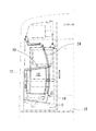
図1〜図3に示される、本発明の実施の形態に係る車両の座席袖仕切り10は、車室内に設置される座席12の側端に位置するものであり、座席端部を通路空間と区分けするパーテーションボード14を有している。又、パーテーションボード14は、図1に示されるように、その下端部が車両の床面15に対して所定間隔Hを空けるようにして、配置される。一方、その上端部は、車内での見通しを確保する為に、立客(成人)の腰位置から胸部位置程度の高さに抑えられている。
そして、パーテーションボード14の、少なくとも座席12と反対側の面には、情報表示部16が設置されている。なお、図示の例では、情報表示部16は、パーテーションボード14の座席12と反対側の面のみならず、座席12側の面にも設けられている。
The vehicle
And the
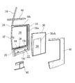
ここで、パーテーションボード14の構造について、図4を参照しながらより具体的に説明する。まず、パーテーションボード14は、強度保持部材として、複数のフレームを適宜組み合わせて構成された、支持枠18を有している。図示の例では、支持枠18は、パーテーションボード14の外枠を構成する縦枠部18a、上横枠部18b及び下横枠部18dに加え、中横枠部18cを有し、全体としてE字状をなしている。そして、支持枠18の2箇所のコ字状開放部20、22のうち、縦枠部18a、上横枠部18b及び中横枠部18cで囲まれた開放部20は、縦枠部18a、中横枠部18c及び下横枠部18dで囲まれた開放部22よりも大開口に形成され、ここに情報表示部16(図1〜図3参照)が配置される。
支持枠18の縦枠部18aは、車両の内壁部又は車体構体に固定されるものである(図1、図2(c)参照)。又、上横枠部18bの先端部には、上部ブラケット26が設けられている。この上部ブラケット26は、スタンションポール24を挿通した状態で、スタンションポール24に固定されるものである。又、中横枠部18c及び下横枠部18dの先端部を架橋するようにして、下部ブラケット28が設けられている。この下部ブラケット28は、スタンションポール24を挿通した状態で、スタンションポール24に固定されるものである。
Here, the structure of the
The
支持枠18の開放部20には、図2(c)にも示されるように、三層の透明プレート30a、30b、30cを重ね合わせてなる透過部30が固定される。透過部30を構成する三層の透明プレートのうち、外部に露出する二層の透明プレート30a、30bは、必要な強度を確保するための厚みを有しており、これらに挟まれる内部一層のプレート30cは、情報表示媒体としての、広告紙32の厚みプラスアルファの幅を有している。そして、内部一層のプレート30cには、広告紙32を配置するための空間部34を形成するための切り欠き30cN(図3(a)、図4参照)が形成されている。そして、内部一層のプレート30cは、透過部30の強度保持部材であると共に、空間部34の厚み方向の必要寸法(広告紙32を抜き差し及び格納可能とする寸法)を確保する為のスペーサとしても機能するものである。又、切り欠き30cNは、透過部30の内層側に設けられた空間部34が、広告紙32の外形に習った寸法形状を有するように形成されている。
なお、各プレート30a〜30cはポリカーボネート等の透明樹脂材料が用いられるが、適宜、強化ガラスその他の透明材料で構成することとしても良い。
As shown in FIG. 2C, the
In addition, although transparent resin materials, such as a polycarbonate, are used for each
パーテーションボードの下端部には、透過部30の内層側に設けられた空間部34に対して、広告紙32を抜き差しするための開口部36、38が形成されている。図示の例では、支持枠18の中横枠部18c及び下横枠部18dの、夫々、透過部30の空間部34と対向する位置に、開口部36(図4参照)及び38(図3(b)参照)が、下方に向けて開放するように形成されている。
又、これらの開口部36、38に挿入可能なホルダ40を備えている。ホルダ40は、図3(b)、図4に示されるように、広告紙32を挟みこむための挟持部40aと、下横枠部18dに固定されることで開口部38を覆い隠す固定部40bとが、連結部40cによって、連結された構造を有している。この連結部40cは、挟持部40aに保持される広告紙32の高さ方向位置を決定するものであり、適宜、広告紙32の大きさに応じて伸縮可能な構造を採用することとしても良い。挟持部40aは、例えば板材を折り返して広告紙32を挟持可能に構成したものであり、開口部36、38に挿通可能な寸法を有している。又、固定部40bは、下横枠部18dの下面に密着するように、下横枠部18dに倣った形状を有しており、例えば、ねじ42等の固定部材を用いて下横枠部18dに固定されるものである。連結部40cは、挟持部40aと共に開口部36、38へと挿通可能な寸法を有している。
At the lower end of the partition board,
A
更に、支持枠18の両側には、側部カバー44、46が装着される。これら側部カバー44、46は、少なくとも透過部30の空間部34に挿入された広告紙32が覆い隠されることの無いように、コ字状をなしている。そして、上横枠部18bには、図4に示される上部カバー48が装着される。
又、図2に示されるように、透過部30の先端縁部には、チャンネル材からなる縁カバー50が固定される。そして、縁カバー50とスタンションポール24との間には、スタンションポール24を握ることができるように空間が形成され、縁カバー50がスタンションポール24に対して、例えばU字状のステー52を介して固定されている。更に、図2(c)に示されるように、透過部30の、支持枠18の縦枠部18aと対向する端縁部は、クッション54を介して縦枠部18a及び側部カバー44、46に対し当接している。図示は省略するが、透過部30の、上横枠部18b及び中横枠部18cと対向する端縁部も同様である。
Further, side covers 44 and 46 are mounted on both sides of the
Further, as shown in FIG. 2, an
そして、本発明の実施の形態に係る車両の座席袖仕切り10は、上記構造を有することで、適宜、座席12、パーテーションボード14、スタンションポール24を、個々に車体から取り外すことも可能となっている。
And the
さて、上記構成をなす本発明の実施の形態によれば、次のような作用効果を得ることが可能となる。まず、本発明の実施の形態に係る車両の座席袖仕切り10は、座席12の端部を通路空間PA(図5参照)と区分けするパーテーションボード14によって、座席12の端部と通路空間PAとを、物理的に確実に仕切ることが可能である。すなわち、パーテーションボード14は、座席12の端部と通路空間PAとを面状に仕切ることから、座席端部の着座客と立客との直接的な干渉が生じることは無く、又、側扉56(図5参照)の開放時に車内に吹き込む風も遮蔽して、着座客へと風が直接的に当ることも無い。そして、座席12の端部と通路空間PAとの間に面状に広がるパーテーションボード14の、側面に設けられた情報表示部16において表示される情報を、乗客に示すことが可能となる。又、情報表示部16の表示内容は、適宜変更可能であることにより、乗客に様々な情報を提供することが可能となる。
Now, according to the embodiment of the present invention configured as described above, the following operational effects can be obtained. First, the
又、本発明の実施の形態に係る車両の座席袖仕切り10は、情報表示部16が、パーテーションボード14の透明板からなる透過部30を介して、透過部30の内層側に形成された空間部34に配置される広告紙32の表示情報を、乗客に提供することが可能である。又、透過部30がパーテーションボード14の外壁を形成するものであることから、広告紙32自体に十分な強度を与えることなく、透過部30の内層側に形成された空間34に格納する態様で、広告紙32を設置することが可能である。又、透過部30によって広告紙32が外力から保護されることとなる。
Further, in the vehicle
又、本発明の実施の形態に係る車両の座席袖仕切り10は、パーテーションボード14の下端部に開口部38(36)が形成され、この開口部38(36)から、透過部30の内層側に設けられた空間部34に対して広告紙32を抜き差しすることで、広告紙32の交換を行なうものである(図5参照)。しかも、パーテーションボード14の下端部が、車両の床面15に対して所定間隔Hを空けて配置されていることで、広告紙32交換作業を容易にするための作業空間が確保されている。また、開口部38(36)がパーテーションボード14の下端部に形成されていることで、開口部38が乗客の目につき難く、乗客によるいたずら防止に貢献するものとなる。又、開口部38(36)が下方へ向けて開放するように形成されていることで、開口部38(36)から透過部30の内層側に設けられた空間部34に対して埃等の異物が入りにくく、メンテナンス性にも配慮したものとなっている。
Further, in the vehicle
又、本発明の実施の形態に係る車両の座席袖仕切り10はホルダ40を備え、このホルダ40に広告紙32を取り付けた状態で、開口部38(36)に対して広告紙32を抜き差しすると共に、ホルダ40によって開口部38を覆い隠すことで、このホルダ40を介して、パーテーションボード14に対する広告紙32の交換、固定、及び開口部の封止を行なうものである。そして、広告紙32単独でパーテーションボード14に対する交換、固定、及び開口部の封止を行なう場合に比べ、これらの作業を簡単かつ確実に行なうことが可能となる。
Further, the
なお、図示は省略するが、パーテーションボード14の上端部に開口部が形成され、この開口部から、透過部30の内層側に設けられた空間部34に対して情報表示媒体を抜き差しすることで、情報表示媒体の交換を行なうように構成することも可能である。この場合には、座席の袖仕切り10を構成するパーテーションボード14は、通常、車内での見通しを確保する為に、その上端部は立客の腰位置から胸部位置程度の高さに抑えられている。このため、広告紙32の交換作業を行なうための作業空間が、パーテーションボード14の上方に確保されており、広告紙32の交換作業が、パーテーションボード14の上方から容易に行なわれるものとなる。
Although illustration is omitted, an opening is formed in the upper end portion of the
更なる応用例として、図示は省略するが、透過部30の一部又は全部が、パーテーションボード14に対して着脱ないし開閉自在に構成され、透過部30の内層側に設けられた空間部34に対して、広告紙32を抜き差しするための開口部が、透過部30の取外し又は開放状態において形成される構造を採用することも可能である。この場合には、例えば、透過部30を構成する三層の透明プレートのうち、座席と反対側の面に露出する一層の透明プレート30aを着脱自在、若しくはヒンジによって他の2層の透明プレート30b、30cに対し開閉自在に構成することで、上記構造が実現される。又、透過部30の全体が支持枠18に対して着脱自在、若しくは、ヒンジによって支持枠18に対し揺動自在に支持されるものであっても良い。
これらの構成によっても、広告紙32の交換作業が、パーテーションボード14の、通路空間A側から、容易に行なうことが可能となる。
As a further application example, although not shown in the drawing, a part or all of the
Also with these configurations, the
又、本発明の実施の形態に係る車両の座席袖仕切り10は、情報表示媒体が、広告紙32等、シート状をなしていることで、透過部30の内層側に設けられた空間部34に要求される厚み方向の必要寸法が、シート状の情報表示媒体を抜き差し及び格納可能な程度に抑えることとなり、パーテーションボード14の厚みの増大を防ぐものとなる。又、情報表示媒体が弾性変形可能であることにより、開口部38(36)から、透過部30の内層側に設けられた空間部34に対して情報表示媒体を抜き差しする際に、適宜、交換作業を容易かつ円滑に行なえるように、情報表示媒体を変形させて作業を行うことが可能となる(図5参照)。しかも、情報表示媒体を取り付けるホルダ40を用いることにより、情報表示媒体が不用意に変形しやすいものであっても、開口部38(36)を介しての情報表示媒体の交換及び固定作業が、ホルダ40を介して確実に行なわれるものとなる。
Further, in the
そして、本発明の実施の形態では、情報表示媒体が広告紙32であることにより、異なる情報が印刷された広告紙32を情報表示部16に設置することで、パーテーションボード14に、印刷された情報の表示機能を与えることが可能となる。又、広告紙32を適宜交換することで、乗客に様々な情報を提供することが可能となる。
又、透過部30の内層側に設けられた空間部34が、広告紙32の外形に習った形状を有していることから、広告紙32を空間部34に差し込むことで、パーテーションボード14に対する情報表示媒体の位置決めがなされるものとなる。例えば、鉄道車両への適用に際しては、車内側天井に掲載される定型の広告紙の寸法に合わせて、透過部30の内層側に設けられた空間部34を形成することで、空間部34の寸法形状も、定型の広告紙に適合するように一義的に決定されるものとなる。
In the embodiment of the present invention, since the information display medium is the
In addition, since the
更に、本発明の実施の形態に係る車両の座席袖仕切り10に用いられる、情報表示媒体は、広告紙32に限定されるものではなく、他のシート状の情報表示媒体、例えば液晶シートを用いることも可能である。この場合でもパーテーションボード14に、液晶シートに表示された情報の表示機能を与えるものとなる。又、液晶シートの表示内容を適宜変更することで、乗客に様々な情報を提供するものとなる。
又、情報表示媒体の照明手段を設けることとすれば、広告や液晶シート等、非自発光型の表示媒体を照明手段によって適宜照明することで、車内の明るさの如何にかかわらず、乗客に対して明確に情報を提供するものとなる。なお、パーテーションボード14の内部に、透過部30を照らす照明手段を設けることとしても、パーテーションボード14の外部から、透過部30を照らす照明手段を設けることとしても良い。
Furthermore, the information display medium used for the
In addition, if an illumination means for the information display medium is provided, a non-self-luminous display medium such as an advertisement or a liquid crystal sheet is appropriately illuminated by the illumination means, so that passengers can be illuminated regardless of the brightness in the vehicle. It will provide clear information. In addition, it is good also as providing the illumination means which illuminates the permeation |
更に、情報表示媒体が、例えば有機EL等の自発光型表示シートを用いることとすれば、パーテーションボードに、自発光型表示シートに表示された情報の表示機能を与えるものとなる。又、自発光型表示シートの表示内容を適宜変更することで、乗客に様々な情報を提供するものとなる。
又、本発明の実施の形態では、情報表示部16が、パーテーションボード14の座席12と反対側の面のみならず、座席12側の面にも設けられていることから、着座客によって隠されない範囲内において、座席12側の面からも乗客に情報提供をすることが可能となり、また、立客のみならず着座客に対しても、例えば視覚的に癒し効果のある模様や色彩等を提供し、或いは、必要な情報を提供するものとなる。一方、諸条件を考慮して、情報表示部16が、パーテーションボード14の座席12と反対側の面にのみ設ける場合もある。この場合には、透過部30の、座席12側に面する透明プレート30b(図2(c)参照)を不透明プレートで構成し、又は、座席12側に面する側部カバー46によって透過部30を覆い隠すように構成することも可能である。
Further, if the information display medium uses a self-luminous display sheet such as an organic EL, for example, the function of displaying information displayed on the self-luminous display sheet is given to the partition board. Moreover, various information is provided to the passenger by appropriately changing the display content of the self-luminous display sheet.
In the embodiment of the present invention, the
又、本発明の実施の形態では、座席12としてロングシートを備える車両の座席袖仕切り10を例示して説明したが、上述のごとき情報提供機能に鑑み、例えば、クロスシートの座席側面に車両の座席袖仕切り10を設置することとしても良い。又、鉄道車両に限定されず、他の旅客用車両の座席袖仕切りにも、同様に採用することも有用である。
Further, in the embodiment of the present invention, the
10:車両の座席袖仕切り、12:座席、14:パーテーションボード、15:床面、16:情報表示部、30:透過部、32:広告紙、34:空間部、 36、38:開口部、40:ホルダ 10: Vehicle seat sleeve partition, 12: Seat, 14: Partition board, 15: Floor surface, 16: Information display part, 30: Transmission part, 32: Advertising paper, 34: Space part, 36, 38: Opening part, 40: Holder
Claims (6)
座席端部を通路空間と区分けするパーテーションボードを有し、該パーテーションボードの、少なくとも座席と反対側の面には、その表示内容を適宜変更可能に、情報表示部が設置されていることを特徴とする車両の座席袖仕切り。 A sleeve divider located at the side edge of a seat installed in the passenger compartment,
It has a partition board that separates the end of the seat from the aisle space, and an information display section is installed on the surface of the partition board at least on the side opposite to the seat so that the display content can be changed as appropriate. Vehicle seat sleeve divider.
Priority Applications (1)
| Application Number | Priority Date | Filing Date | Title |
|---|---|---|---|
| JP2012191749A JP5972114B2 (en) | 2012-08-31 | 2012-08-31 | Vehicle seat sleeve divider |
Applications Claiming Priority (1)
| Application Number | Priority Date | Filing Date | Title |
|---|---|---|---|
| JP2012191749A JP5972114B2 (en) | 2012-08-31 | 2012-08-31 | Vehicle seat sleeve divider |
Publications (2)
| Publication Number | Publication Date |
|---|---|
| JP2014046833A true JP2014046833A (en) | 2014-03-17 |
| JP5972114B2 JP5972114B2 (en) | 2016-08-17 |
Family
ID=50606923
Family Applications (1)
| Application Number | Title | Priority Date | Filing Date |
|---|---|---|---|
| JP2012191749A Expired - Fee Related JP5972114B2 (en) | 2012-08-31 | 2012-08-31 | Vehicle seat sleeve divider |
Country Status (1)
| Country | Link |
|---|---|
| JP (1) | JP5972114B2 (en) |
Cited By (4)
| Publication number | Priority date | Publication date | Assignee | Title |
|---|---|---|---|---|
| WO2019198587A1 (en) * | 2018-04-12 | 2019-10-17 | 株式会社フィナンシャル総合研究所 | Sliding-door opening and closing device |
| JP2020050309A (en) * | 2018-09-28 | 2020-04-02 | 株式会社総合車両製作所 | In-vehicle guide system and in-vehicle guide method for railway vehicle |
| JP2021024417A (en) * | 2019-08-05 | 2021-02-22 | 日本車輌製造株式会社 | Sleeve partition for railway vehicle and railway vehicle including sleeve partition for railway vehicle |
| JP2021120269A (en) * | 2021-04-09 | 2021-08-19 | 株式会社フィナンシャル総合研究所 | Sliding door opening/closing device |
Citations (8)
| Publication number | Priority date | Publication date | Assignee | Title |
|---|---|---|---|---|
| EP0348096A2 (en) * | 1988-06-18 | 1989-12-27 | Flight Equipment And Engineering Limited | Vehicle passenger seating |
| JPH0384583A (en) * | 1989-08-29 | 1991-04-10 | Susumu Nemoto | Hook with holder function for advertisement paper |
| JPH0528333A (en) * | 1991-07-22 | 1993-02-05 | Mitsubishi Precision Co Ltd | Automatic ticket inspection system |
| JP2000043719A (en) * | 1998-07-30 | 2000-02-15 | Hitachi Ltd | Train car |
| JP3068138U (en) * | 1999-07-02 | 2000-04-28 | 交通広告株式会社 | Floor sheet |
| JP2003225144A (en) * | 2002-02-05 | 2003-08-12 | Suminoe Textile Co Ltd | Seat with advertising information |
| JP2005247146A (en) * | 2004-03-04 | 2005-09-15 | Tokyu Car Corp | Sleeve screen |
| JP2012011962A (en) * | 2010-07-05 | 2012-01-19 | Kawasaki Heavy Ind Ltd | Wind screen structure for railway vehicle, and manufacturing method of the same |
-
2012
- 2012-08-31 JP JP2012191749A patent/JP5972114B2/en not_active Expired - Fee Related
Patent Citations (9)
| Publication number | Priority date | Publication date | Assignee | Title |
|---|---|---|---|---|
| EP0348096A2 (en) * | 1988-06-18 | 1989-12-27 | Flight Equipment And Engineering Limited | Vehicle passenger seating |
| JPH02106449A (en) * | 1988-06-18 | 1990-04-18 | Flight Equip & Eng Ltd | Seat for passenger of car |
| JPH0384583A (en) * | 1989-08-29 | 1991-04-10 | Susumu Nemoto | Hook with holder function for advertisement paper |
| JPH0528333A (en) * | 1991-07-22 | 1993-02-05 | Mitsubishi Precision Co Ltd | Automatic ticket inspection system |
| JP2000043719A (en) * | 1998-07-30 | 2000-02-15 | Hitachi Ltd | Train car |
| JP3068138U (en) * | 1999-07-02 | 2000-04-28 | 交通広告株式会社 | Floor sheet |
| JP2003225144A (en) * | 2002-02-05 | 2003-08-12 | Suminoe Textile Co Ltd | Seat with advertising information |
| JP2005247146A (en) * | 2004-03-04 | 2005-09-15 | Tokyu Car Corp | Sleeve screen |
| JP2012011962A (en) * | 2010-07-05 | 2012-01-19 | Kawasaki Heavy Ind Ltd | Wind screen structure for railway vehicle, and manufacturing method of the same |
Cited By (6)
| Publication number | Priority date | Publication date | Assignee | Title |
|---|---|---|---|---|
| WO2019198587A1 (en) * | 2018-04-12 | 2019-10-17 | 株式会社フィナンシャル総合研究所 | Sliding-door opening and closing device |
| JP2020050309A (en) * | 2018-09-28 | 2020-04-02 | 株式会社総合車両製作所 | In-vehicle guide system and in-vehicle guide method for railway vehicle |
| JP7202562B2 (en) | 2018-09-28 | 2023-01-12 | 株式会社総合車両製作所 | IN-CAR GUIDANCE SYSTEM AND IN-CAR GUIDANCE METHOD FOR RAIL VEHICLE |
| JP2021024417A (en) * | 2019-08-05 | 2021-02-22 | 日本車輌製造株式会社 | Sleeve partition for railway vehicle and railway vehicle including sleeve partition for railway vehicle |
| JP7398221B2 (en) | 2019-08-05 | 2023-12-14 | 日本車輌製造株式会社 | Railroad vehicle side partitions and railway vehicles equipped with the railroad vehicle side partitions |
| JP2021120269A (en) * | 2021-04-09 | 2021-08-19 | 株式会社フィナンシャル総合研究所 | Sliding door opening/closing device |
Also Published As
| Publication number | Publication date |
|---|---|
| JP5972114B2 (en) | 2016-08-17 |
Similar Documents
| Publication | Publication Date | Title |
|---|---|---|
| US5010668A (en) | Advertising device for airliner seat back or snack tray table | |
| JP5972114B2 (en) | Vehicle seat sleeve divider | |
| US10377494B2 (en) | Aircraft divider assembly | |
| US7834752B2 (en) | Brake-actuated message device | |
| BR102014011990A2 (en) | passenger interface units and assemblies | |
| US20140124623A1 (en) | Aircraft Class Divider | |
| US7406792B2 (en) | Picture frame assembly | |
| US20190291870A1 (en) | Storage pocket | |
| US20190010017A1 (en) | Landing floor door indicator panel | |
| US20060181105A1 (en) | Display element for use for a passenger seat | |
| KR20180011632A (en) | Apparatus for emergency opening safety door of subway platform | |
| CN107650933A (en) | Lightweight EMUs guest room luggage carrier with seat presentation of information | |
| KR20130003416U (en) | Taxidriver protection screen | |
| EP3606820B1 (en) | Aircraft mirror assembly | |
| EP2971423B1 (en) | A double-pane module with an image producing device for use in a structure | |
| CN201999201U (en) | Aisle curtain hanger for economy classes of airliners | |
| CN202450968U (en) | Subway platform safety door with information screen | |
| EP2578442B1 (en) | Seat for passenger transport vehicle and vehicles comprising such a seat | |
| CN207292017U (en) | Lightweight EMU guest room luggage carrier with seat presentation of information | |
| KR200346457Y1 (en) | Wall-Mounted Interior Frame for Subway | |
| JP2020199983A (en) | Replaceable display window for railway vehicle | |
| JP3194294U (en) | Display device | |
| RU2404461C1 (en) | Advertisement-information installation | |
| KR101692996B1 (en) | A safety screen billboard installation structure of a electricity railroad vehicle's room | |
| CN202656939U (en) | Aviation luggage rack for passenger vehicle |
Legal Events
| Date | Code | Title | Description |
|---|---|---|---|
| A621 | Written request for application examination |
Free format text: JAPANESE INTERMEDIATE CODE: A621 Effective date: 20150617 |
|
| A977 | Report on retrieval |
Free format text: JAPANESE INTERMEDIATE CODE: A971007 Effective date: 20160322 |
|
| A131 | Notification of reasons for refusal |
Free format text: JAPANESE INTERMEDIATE CODE: A131 Effective date: 20160330 |
|
| A521 | Request for written amendment filed |
Free format text: JAPANESE INTERMEDIATE CODE: A523 Effective date: 20160510 |
|
| TRDD | Decision of grant or rejection written | ||
| A01 | Written decision to grant a patent or to grant a registration (utility model) |
Free format text: JAPANESE INTERMEDIATE CODE: A01 Effective date: 20160706 |
|
| A61 | First payment of annual fees (during grant procedure) |
Free format text: JAPANESE INTERMEDIATE CODE: A61 Effective date: 20160712 |
|
| R150 | Certificate of patent or registration of utility model |
Ref document number: 5972114 Country of ref document: JP Free format text: JAPANESE INTERMEDIATE CODE: R150 |
|
| LAPS | Cancellation because of no payment of annual fees |