JP2014046871A - Door structure - Google Patents
Door structure Download PDFInfo
- Publication number
- JP2014046871A JP2014046871A JP2012192820A JP2012192820A JP2014046871A JP 2014046871 A JP2014046871 A JP 2014046871A JP 2012192820 A JP2012192820 A JP 2012192820A JP 2012192820 A JP2012192820 A JP 2012192820A JP 2014046871 A JP2014046871 A JP 2014046871A
- Authority
- JP
- Japan
- Prior art keywords
- door
- guide rail
- glass
- vehicle
- sash
- Prior art date
- Legal status (The legal status is an assumption and is not a legal conclusion. Google has not performed a legal analysis and makes no representation as to the accuracy of the status listed.)
- Pending
Links
Images


Landscapes
- Window Of Vehicle (AREA)
Abstract
【課題】ドアの開閉時などにおけるドアガラスの揺動を抑え、さらに異なる車種間で部品の共通化を図ることが可能なドア構造を提供する。
【解決手段】ドア構造100は、ドアサッシュ108とドアガラス104とを含む。ドア構造100は、ドアアウタパネル106およびドアインナパネル102、ドアインナパネル102に上下方向に伸びるよう取り付けられるガイドレール124を有するウィンドレギュレータ120、ドアガラス104の下部に取り付けられてガイドレール124上をスライド可能なキャリアプレート126、ドアサッシュ108および収納空間E1内にてドアガラス104の縁に沿って設置されるガラスラン110、を備える。ガイドレール124は、その下端124aが、ドアサッシュ108に沿って昇降した場合のドアガラス104の仮想軌跡L1と比べて、ドアインナパネル102側に片寄るよう形成されている。
【選択図】図2There is provided a door structure capable of suppressing the swinging of a door glass when the door is opened and closed and further sharing parts among different vehicle types.
A door structure includes a door sash and a door glass. The door structure 100 includes a door outer panel 106, a door inner panel 102, a window regulator 120 having a guide rail 124 attached to the door inner panel 102 so as to extend in the vertical direction, and is attached to a lower portion of the door glass 104 and slides on the guide rail 124. A possible carrier plate 126, a door sash 108, and a glass run 110 installed along the edge of the door glass 104 in the storage space E1. The lower end 124a of the guide rail 124 is formed so as to be offset toward the door inner panel 102 as compared to the virtual locus L1 of the door glass 104 when the guide rail 124 moves up and down along the door sash 108.
[Selection] Figure 2
Description
本発明は、ドアサッシュと、このドアサッシュに沿って昇降するドアガラスとを含んだ車両のドア構造に関するものである。 The present invention relates to a vehicle door structure including a door sash and a door glass that moves up and down along the door sash.
一般的な車両のドア構造は、例えば特許文献1にあるように、ドアガラスがドアサッシュに沿って昇降する構成となっている。このドアガラスの昇降機構として、レール式のウィンドレギュレータが広く普及している。一般的なレール式のウィンドレギュレータは、モータユニットとガイドレールとを有している。このガイドレールにはドアガラスの下部のキャリアプレートがかみ合っていて、モータユニットの動力でケーブルを介してキャリアプレートを昇降させる構造となっている。特許文献1においても、ドアアウタパネルとドアインナパネルとで構成された空間内に、ドアガラスの昇降方向、すなわち上下方向へ伸びるようガイドレールが設置され、これにキャリアプレートがかみ合っている。 A general vehicle door structure has a configuration in which a door glass moves up and down along a door sash, for example, as disclosed in Patent Document 1. Rail type window regulators are widely used as the door glass lifting mechanism. A general rail-type window regulator has a motor unit and a guide rail. A carrier plate below the door glass is engaged with the guide rail, and the carrier plate is lifted and lowered via a cable by the power of the motor unit. Also in patent document 1, the guide rail is installed in the space comprised by the door outer panel and the door inner panel so that it may extend in the raising / lowering direction of the door glass, that is, the vertical direction, and the carrier plate is engaged with this.
ドアガラスは、ドアの開閉時などに、いわゆる「バタつき」と呼ばれる揺動および異音を生じさせることがある。このバタつきは、ドアガラスを中程度に下降させた状態など、ガラスラン等によるドアガラスの支持力が下がっている場合に起こりやすい。特に、レール式のウィンドレギュレータでは、特許文献1にも記載されているとおり、ドアガラスの下部のキャリアプレートとそれを支えるガイドレールとの間に、抵抗を減らすための若干の隙間が確保されているため、バタつきを防ぎきることは難しい。 The door glass may cause a so-called “fluttering” and an abnormal noise when the door is opened and closed. This fluttering is likely to occur when the supporting power of the door glass by a glass run or the like is lowered, such as a state where the door glass is lowered moderately. In particular, in the rail-type window regulator, as described in Patent Document 1, a slight gap for reducing resistance is secured between the carrier plate below the door glass and the guide rail that supports it. Therefore, it is difficult to prevent fluttering.
また、現在では多くの異なるタイプの車種が開発され、さらに同一車種においてもモデルチェンジが大小さまざまな規模で常に行われている。その際、コスト削減の観点から、各車種同士および各モデル同士でできるだけ部品の共通化を図りたいという要望がある。 In addition, many different types of vehicles have been developed at present, and model changes are constantly being made on large and small scales within the same model. At that time, from the viewpoint of cost reduction, there is a demand for sharing parts as much as possible between each vehicle type and each model.
本発明は、このような課題に鑑み、ドアの開閉時などにおけるドアガラスの揺動を抑え、さらに異なる車種間で部品の共通化を図ることが可能なドア構造を提供することを目的とする。 The present invention has been made in view of such a problem, and an object thereof is to provide a door structure capable of suppressing the swinging of the door glass when the door is opened and closed and sharing parts among different vehicle types. .
上記課題を解決するために、本発明にかかるドア構造の代表的な構成は、ドアサッシュと、ドアサッシュに沿って昇降可能なドアガラスとを含んだ車両のドア構造であって、ドアの外装となるドアアウタパネルと、ドアアウタパネルの車内側に連結し、ドアアウタパネルとの間にドアガラスの収納空間を形成するドアインナパネルと、収納空間内にて上下方向へ伸びるようドアインナパネルに取り付けられるガイドレールを有し、ガイドレールに沿ってドアガラスを昇降させるウィンドレギュレータと、ドアガラスの下部に取り付けられ、ガイドレール上をスライド可能なキャリアプレートと、ドアサッシュおよび収納空間内にてドアガラスの縁に沿って設置されてドアガラスとドアサッシュとの隙間をふさぐガラスランと、を備え、ガイドレールは、その下端が、ドアサッシュに沿って昇降した場合のドアガラスの仮想軌跡と比べて、ドアアウタパネル側またはドアインナパネル側のいずれか一方に片寄るよう形成されていることを特徴とする。 In order to solve the above-mentioned problems, a typical structure of a door structure according to the present invention is a door structure of a vehicle including a door sash and a door glass that can be raised and lowered along the door sash. The door outer panel is connected to the inside of the door outer panel and the door inner panel forms a door glass storage space between the door outer panel and the door inner panel so as to extend vertically in the storage space. A window regulator that has a guide rail and moves the door glass up and down along the guide rail, a carrier plate that is attached to the lower part of the door glass and that can slide on the guide rail, and the door sash and the door glass in the storage space. A glass run installed along the edge to close the gap between the door glass and the door sash, and a guide The lower end of the rail is formed so as to be offset toward one of the door outer panel side and the door inner panel side as compared with the virtual locus of the door glass when it is raised and lowered along the door sash. .
上記のガイドレールは下端がドアアウタパネル側またはドアインナパネル側に片寄っているため、これに沿って下降したドアガラスもドアアウタパネル側またはドアインナパネル側にその位置が片寄る。すると、ドアガラスは、ガラスランの車外側または車内側により強く押しつけられることになる。これによって、ドアガラスはガラスランから通常よりも大きな反力を受けることができるため、その揺動が抑えられる。 Since the lower end of the guide rail is offset toward the door outer panel side or the door inner panel side, the position of the door glass descending along the door rail also shifts toward the door outer panel side or the door inner panel side. Then, the door glass is pressed more strongly on the outside or inside of the glass run. As a result, the door glass can receive a reaction force larger than usual from the glass run, so that its swing is suppressed.
上記のガイドレールはさらに、その上端が、仮想軌跡と比べて、ドアアウタパネル側に片寄るよう形成されていてもよい。このガイドレールに沿って上昇したドアガイドレールは、ドアアウタパネル側へその位置が片寄ることになる。ここで、従来のドアガラスでは、閉じきった時に、ウィンドレギュレータのモータのトルクによってドアガラスにさらに車外側へと押し出すような力が加わることがあった。このような力が加わると、キャリアプレートを介して、ガイドレールを設置しているドアインナパネルも車外側へと引っ張られて変形するおそれがある。そこで、上記構成では、ドアガラスを閉じた際にドアガラスがそれ以上車外側へ移動できないよう、ガイドレールの上端をあえて車外側すなわちドアアウタパネル側へと片寄らせていて、これによってドアガラスをガラスランの車外側に押しつけてその移動を防いでいる。したがって、ドアインナパネルの変形の発生も防止できる。 The guide rail may further be formed such that the upper end of the guide rail is offset toward the door outer panel as compared with the virtual trajectory. The position of the door guide rail that has risen along the guide rail is shifted toward the door outer panel. Here, in the conventional door glass, when the door glass is completely closed, a force that pushes the door glass further to the outside of the vehicle may be applied by the torque of the motor of the window regulator. When such a force is applied, the door inner panel on which the guide rail is installed may also be pulled outside the vehicle via the carrier plate and deformed. Therefore, in the above configuration, when the door glass is closed, the upper end of the guide rail is deviated toward the vehicle outer side, that is, the door outer panel side so that the door glass cannot move further outside the vehicle. It is pressed against the outside of the run to prevent its movement. Therefore, it is possible to prevent the door inner panel from being deformed.
上記課題を解決するために、本発明にかかるドア構造の他の代表的な構成は、ドアサッシュと、ドアサッシュに沿って昇降可能なドアガラスとを含んだ車両のドア構造であって、ドアの外装となるドアアウタパネルと、ドアアウタパネルの車内側に連結し、ドアアウタパネルとの間にドアガラスの収納空間を形成するドアインナパネルと、収納空間内にて上下方向へ伸びるようドアインナパネルに取り付けられるガイドレールを有し、ガイドレールに沿ってドアガラスを昇降させるウィンドレギュレータと、ドアガラスの下部に取り付けられ、ガイドレール上をスライド可能なキャリアプレートと、を備え、ガイドレールは、その上端が、ドアサッシュに沿って昇降した場合のドアガラスの仮想軌跡と比べて、ドアアウタパネル側に片寄るよう形成されていることを特徴とする。 In order to solve the above problems, another typical structure of a door structure according to the present invention is a door structure of a vehicle including a door sash and a door glass that can be moved up and down along the door sash. A door outer panel that is connected to the inside of the door outer panel and forms a door glass storage space between the door outer panel and a door inner panel that extends vertically in the storage space. A window regulator for moving the door glass up and down along the guide rail; and a carrier plate attached to the lower portion of the door glass and slidable on the guide rail, the guide rail having an upper end Compared to the virtual trajectory of the door glass when it goes up and down along the door sash, it moves closer to the door outer panel side. Characterized in that it is formed.
上記構成においても、ガイドレールの上端をあえてドアアウタパネル側へと片寄らせていて、これによってドアガラスを閉じた際にドアガラスがそれ以上車外側へ移動できないようにし、これによってドアインナパネルの変形の発生を防いでいる。 Even in the above configuration, the upper end of the guide rail is deviated to the door outer panel side, so that when the door glass is closed, the door glass cannot move further outside the vehicle, thereby deforming the door inner panel. Is prevented.
上記のガイドレールおよび仮想軌跡は、車幅方向の縦断面において、車内側に中心を有する円弧をそれぞれ描いていて、ガイドレールおよび仮想軌跡は、円弧の曲率が互いに異なっているとよい。このように、ガイドレールおよびドアガラスとその軌跡を円弧状に設定したうえでも、前述したようにガイドレールをその下端や上端が車幅方向のどちらかに片寄るよう配置することは可能である。そして、ガイドレールおよび仮想軌跡の曲率をあえて互いに異なるものに設定することで、従来はそれらを車種ごとに同一の曲率で製造していたところ、例えばガイドレールを異なる車種間で流用するなどの部材の共通化が図りやすくなる。したがって、コストダウンも図ることが可能になる。 The guide rail and the virtual trajectory may each draw an arc having a center inside the vehicle in the longitudinal section in the vehicle width direction, and the guide rail and the virtual trajectory may have different arc curvatures. As described above, it is possible to dispose the guide rail so that the lower end or the upper end of the guide rail is deviated in either the vehicle width direction as described above even when the guide rail and the door glass and their trajectories are set in an arc shape. And, by setting the curvatures of the guide rail and the virtual trajectory to be different from each other, conventionally, they have been manufactured with the same curvature for each vehicle type. For example, members that divert the guide rail between different vehicle types, etc. Can be easily shared. Therefore, it is possible to reduce the cost.
上記課題を解決するために、本発明にかかるドア構造の他の代表的な構成は、ドアサッシュと、ドアサッシュに沿って昇降可能なドアガラスとを含んだ車両のドア構造であって、ドアの外装となるドアアウタパネルと、ドアアウタパネルの車内側に連結し、ドアアウタパネルとの間にドアガラスの収納空間を形成するドアインナパネルと、収納空間内にて上下方向へ伸びるようドアインナパネルに取り付けられるガイドレールを有し、ガイドレールに沿ってドアガラスを昇降させるウィンドレギュレータと、ドアガラスの下部に取り付けられ、ガイドレール上をスライド可能なキャリアプレートと、ドアサッシュおよび収納空間内にてドアガラスの縁に沿って設置されてドアガラスとドアサッシュとの隙間をふさぐガラスランと、を備え、車幅方向の縦断面におけるガイドレールおよびドアサッシュに沿って昇降した場合のドアガラスの仮想軌跡は、車内側に中心を有する円弧をそれぞれ描き、円弧の曲率が互いに異なっていて、ガイドレールは、車幅方向の縦断面において、その上端および下端に比べて中央が仮想軌跡側へ片寄った形状、またはその上端および下端に比べて中央が仮想軌跡から離間した形状を有していることを特徴とする。 In order to solve the above problems, another typical structure of a door structure according to the present invention is a door structure of a vehicle including a door sash and a door glass that can be moved up and down along the door sash. A door outer panel that is connected to the inside of the door outer panel and forms a door glass storage space between the door outer panel and a door inner panel that extends vertically in the storage space. A window regulator that has a guide rail that can be attached and moves the door glass up and down along the guide rail, a carrier plate that is attached to the lower part of the door glass and that can slide on the guide rail, and a door in the door sash and storage space A glass run installed along the edge of the glass to close the gap between the door glass and the door sash; The virtual trajectory of the door glass when moving up and down along the guide rail and the door sash in the longitudinal section of the direction draws an arc having a center on the inside of the car, and the curvature of the arc is different from each other. In the longitudinal cross section in the direction, the center is shifted to the virtual locus side compared to the upper end and the lower end, or the center is separated from the virtual locus compared to the upper end and the lower end.
上記構成では、ガイドレールの中央が仮想軌跡側へ片寄った形状の場合、またはガイドレールの中央が仮想軌跡から離間した形状の場合のいずれにおいても、ドアガラスは、昇降方向の中央部分に位置するとき、ガラスランにより強く押しつけられて大きな反力を受ける。したがって、その状態においてドアの開閉を行ったとしても、ドアガラスの揺動は抑えられる。また、ガイドレールおよび仮想軌跡の曲率をあえて互いに異なるものに設定することで、それらを同一の曲率で車種ごとに製造する場合よりも、部材の共通化が図りやすくなる。したがって、コストダウンを図ることも可能になる。 In the above configuration, the door glass is positioned at the central portion in the ascending / descending direction regardless of whether the center of the guide rail has a shape that is offset toward the virtual locus or the center of the guide rail has a shape that is separated from the virtual locus. When it is strongly pressed by the glass run, it receives a large reaction force. Therefore, even if the door is opened and closed in that state, the swing of the door glass can be suppressed. In addition, by setting the curvatures of the guide rail and the virtual trajectory to be different from each other, it becomes easier to share the members than when manufacturing them for each vehicle type with the same curvature. Therefore, it is possible to reduce the cost.
本発明によれば、ドアの開閉時などにおけるドアガラスの揺動を抑え、さらに異なる車種間で部品の共通化を図ることが可能なドア構造を提供することが可能となる。 ADVANTAGE OF THE INVENTION According to this invention, it becomes possible to provide the door structure which can suppress rocking | fluctuation of a door glass at the time of opening and closing of a door, and can aim at commonization of components between different vehicle types.
以下に添付図面を参照しながら、本発明の好適な実施形態について詳細に説明する。かかる実施形態に示す寸法、材料、その他具体的な数値などは、発明の理解を容易とするための例示に過ぎず、特に断る場合を除き、本発明を限定するものではない。なお、本明細書及び図面において、実質的に同一の機能、構成を有する要素については、同一の符号を付することにより重複説明を省略し、また本発明に直接関係のない要素は図示を省略する。 Hereinafter, preferred embodiments of the present invention will be described in detail with reference to the accompanying drawings. The dimensions, materials, and other specific numerical values shown in the embodiments are merely examples for facilitating understanding of the invention, and do not limit the present invention unless otherwise specified. In the present specification and drawings, elements having substantially the same function and configuration are denoted by the same reference numerals, and redundant description is omitted, and elements not directly related to the present invention are not illustrated. To do.
(第1実施形態)
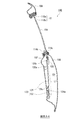
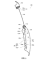
図1は、本発明の第1実施形態にかかるドア構造100を示す図である。図1に示すドア構造100は、車両の右側のフロントドアを想定したものであって、車内側から見てドアインナパネル102を透過して図示を行っている。当該ドア構造100のドアガラス104は、電動で昇降するいわゆるパワーウィンドウであって、その昇降機構としてレール式のウィンドレギュレータ120を備えている。
(First embodiment)
FIG. 1 is a view showing a
図2を参照して、ドア構造100の基本構成から説明する。図2は、図1のA―A断面図である。このA−A断面は、ドア構造100の車幅方向の縦断面である。図2に示すように、当該ドア構造100には、外装となるドアアウタパネル106と、このドアアウタパネル106に車内側から連結しているドアインナパネル102が含まれている。そして、これらパネル部材の間にドアガラス104の収納空間E1が形成されている。
The basic structure of the
図1に示すように、ドアガラス104は、窓枠であるドアサッシュ108に囲われていて、このドアサッシュ108に沿って昇降する。ドアサッシュ108には、ドアガラス104の縁に沿ってガラスラン110が設けられている。ガラスラン110は、ドアサッシュ108とドアガラス104との間の隙間を封じる、樹脂またはゴム製で弾性を有するシール部材である。図2に示すように、ガラスラン110は溝状になっていて、車外側のリップ部110a、および車内側のリップ部110bによってドアガラス104を挟むように支えている。図1に示すように、ガラスラン110の端部112a・112bはドアサッシュ108よりも下方の収納空間E1内にまで延びていて、ドアガラス104を降下させた状態においてもその縁を挟んでいて、その昇降を案内する。
As shown in FIG. 1, the
また、ドアインナパネル102およびドアアウタパネル106(図2参照)の上縁には、ウェザストリップ114a・114bが備えられている。ウェザストリップ114a・114bもまた、ガラスラン110と同じく、樹脂製のシール部材である。図2に示すように、ドアアウタパネル106の上縁にはウェザストリップ114aが備えられ、ドアインナパネル102の上縁にはウェザストリップ114bが備えられ、これらによってドアガラス104と各パネルとの隙間が封じられている。
Weather strips 114a and 114b are provided on the upper edges of the door
図1を参照して、ドアガラス104の昇降機構について説明する。ウィンドレギュレータ120は、モータユニット122、およびガイドレール124を備えている。モータユニット122は、モータの回転力を動力源として、ケーブル(図示省略)を介してガイドレール124上のキャリアプレート126を昇降させる。ガイドレール124は、上下のブラケット128a・128bによって、上下方向へ伸びるようにドアインナパネル102に設置されている。ガイドレール124にかみ合っているキャリアプレート126は、ドアガラス104の下部に取り付けられた部材であって、上述したようにケーブルに引っ張られることでガイドレール124上をスライドする。
With reference to FIG. 1, the raising / lowering mechanism of the
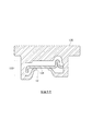
図3は、図1のB−B断面図である。図3に例示するように、キャリアプレート126にはガイドレール124にかみ合うための溝部130が形成されている。この溝部130の縁の所定箇所には、ガイドレール124の背面側にまわり込むようバネ形状部131が設けられている。バネ形状部131は樹脂で形成されていて、弾性を有し、ガイドレール124を溝部130の内側に押しつけている。このバネ形状部131を有することで、キャリアプレート126はガイドレール124に沿ってスライドすることが可能になっている。
3 is a cross-sectional view taken along line BB in FIG. As illustrated in FIG. 3, the
当該ドア構造100では、ウィンドレギュレータ120の構成を工夫することで、ドアガラス104のいわゆるバタつきと呼ばれる揺動および異音を抑えることが可能になっている。例えば図2に示したように、本実施形態では、ガイドレール124の下端124aが、ドアインナパネル102側に片寄るように形成されている。
In the
通常であれば、ドアガラス104は、ドアサッシュ108およびガラスラン110に沿って昇降した場合の仮想軌跡L1に沿って昇降する。これに対して、本実施形態のガイドレール124は、その下端124aを、仮想軌跡L1と比べて、ドアインナパネル102側に片寄らせている。すると、下降したドアガラス104は、その位置が仮想軌跡上よりも車内側の位置になる。
Normally, the
図4は、図1のガラスラン110の各断面図である。図4(a)は図1のドアガラス104を下降させた場合におけるC−C断面図であって、図4(c)はその比較例であるドア構造10を例示した図である。本実施形態のドア構造100では、上述した図2のガイドレール124の構造によって、下降したドアガラス104が通常よりも車内側に位置する。すると、図4(c)のドア構造10のドアガラス20がガラスラン110の中央に位置しているのに対し、図4(a)の当該ドア構造100のドアガラス104はガラスラン110のうちの特に車内側のリップ部110bにより強く押しつけられる。
FIG. 4 is a cross-sectional view of the
このように、当該ドア構造100では、ドアガラス104が、ガラスラン110の車内側のリップ部110bから通常よりも大きな反力を受ける。このリップ部110bによってドアガラス104は支えられ、ドアを開閉した場合などにおいても揺動することがなく、それに伴う異音の発生も抑えられる。通常、下降したドアガラス104は、その上辺がガラスラン110に支えられていないために、揺動がより起こりやすくなっている。その点において、本実施形態の構成は、非常に有効である。
Thus, in the
また、本実施形態では、揺動の防止以外にも、ドアガラスを閉じきった時にドアインナパネル102に変形が起こらないよう配慮して、ガイドレール124の形状を設定している。具体的には、図2に示すように、ガイドレール124は、その上端124bが、仮想軌跡L1と比べて、ドアアウタパネル106側に片寄るよう形成されている。
In this embodiment, the shape of the
このガイドレール124に沿って上昇したドアガラス104は、ドアアウタパネル106側へその位置が片寄ることになる。ここで、従来のドアガラスでは、閉じきった時に、ウィンドレギュレータ120のモータのトルクによってドアガラスがさらに上昇を続けようとし、結果としてウィンドレギュレータ120のケーブル(図示省略)を通じてドアガラスに車外側へと押し出すような力が加わることがあった。このような力が加わると、キャリアプレート126を介して、ガイドレール124を設置しているドアインナパネル102も車外側へと引っ張られ、変形が生じるおそれがある。
The position of the
そこで、本実施形態では、ドアガラス104を閉じた際にドアガラス104がそれ以上車外側へ移動できないよう、ガイドレール124の上端124bをあえて車外側すなわちドアアウタパネル106側へと片寄らせている。
Therefore, in this embodiment, when the
図4(b)は図1のD−D断面図である。上述した図2のガイドレール124の上端124bが車外側へ片寄っていることで、上昇したドアガラス104も、特にその下部において、通常の状態(図4(c)参照)よりも車外側に位置する。これにより、ドアガラス104はガラスラン110のうちの特に車外側のリップ部110aにより強く押しつけられている。
FIG. 4B is a sectional view taken along the line DD of FIG. The above-described
図5は、図2のウェザストリップ114a・114bの拡大図である。図5(a)は本実施形態のドア構造100に含まれるウェザストリップ114a・114bを示していて、図5(b)は比較例であるドア構造10を例示した図である。図5(b)のドア構造10におけるドアガラス20は、ウェザストリップ114a・114bの中間に位置しているのに対し、図5(a)の本実施形態のドア構造100のドアガラス104は、図2で示したガイドレール124の構造によって車外側に位置し、ウェザストリップ114aに強く押しつけられている。
FIG. 5 is an enlarged view of the weather strips 114a and 114b in FIG. FIG. 5A shows the weather strips 114a and 114b included in the
以上のように、当該ドア構造100のドアガラス104は、閉じた際に、図4(b)のガラスラン110の車外側のリップ部110a、および図5(a)の車外側のウェザストリップ114aに押しつけられ、それ以上の車外側への移動が防がれている。したがって、ドアガラス104の車外側への移動に伴うドアインナパネル102の変形も防がれている。この構成であれば、補強部材等を追加することなく、ドアインナパネル102の変形が防げるため、コストの増加を招くことがなく、好適である。
As described above, when the
(第2実施形態)
図6は、第2実施形態にかかるドア構造200を示した図である。図6に示すドア構造200は、ウィンドレギュレータ201のガイドレール202の形状の点において、図2のドア構造100と異なっている。ガイドレール202は、下端202aが、仮想軌跡L1に比べて、ドアアウタパネル106側に片寄っている。この構成によると、下降したドアガラス104は、その位置が、仮想軌跡L1上よりも車外側に位置する。この構成によっても、図4(b)を参照して説明したように、ガラスラン110の車外側のリップ部110aにより強く押しつけられ、より大きな反力を受ける。したがって、ドア構造200においても、ドアを開閉した際などにおけるドアガラス104の揺動を抑えることが可能になる。
(Second Embodiment)
FIG. 6 is a view showing a
(第3実施形態)
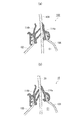
図7は、第3実施形態にかかるドア構造300を示した図である。このドア構造300もまた、ウィンドレギュレータ302のガイドレール304の形状の点において、各実施形態のドア構造と構成が異なっている。本実施形態のガイドレール304および仮想軌跡L1は、図中に示す車幅方向の縦断面において、車内側に中心を有するようにして円弧をそれぞれ描いている。これらガイドレール304および仮想軌跡L1の円弧は曲率が互いに異なり、ガイドレール304の曲率(Rr)が仮想軌跡L1の曲率(Rg)よりも小さくなっている(Rr<Rg)。
(Third embodiment)
FIG. 7 is a view showing a
このように、ガイドレール304およびドアガラス104とその仮想軌跡L1を円弧状に設定しても、ガイドレール304をその下端304aおよび上端304bが車幅方向のどちらかに片寄るよう配置することは可能である。例えば、ガイドレール304は、下端304aおよび上端304bが、仮想軌跡L1から離れるようにして、ドアインナパネル102側へ片寄っている。言い換えると、ガイドレール304は、中央部304cが、下端304aおよび上端304bに比べて仮想軌跡L1側へ片寄った形状をしている。
As described above, even if the
本実施形態によれば、ドアガラス104は、昇降方向の中間部分に位置するとき、仮想軌跡L1上よりも車外側に片寄ることになる。その際、ドアガラス104は、ガラスラン110の車外側のリップ部110a(図4(b)参照)により強く押しつけられ、大きな反力を受ける。これによって、ドアガラス104は揺動を抑えることが可能になる。なお、図中に示す構成とは反対に、ガイドレール304を、その中央が下端および上端に比べて仮想軌跡L1から車内側へ離間した形状(例えば、ガイドレールを曲率Rgよりも大きな曲率に設定する)としても、ドアガラス104がガラスラン110の車内側のリップ部110b(図4(a)参照)に強く押しつけられるため、同様の効果を得ることが可能である。
According to the present embodiment, when the
また、ガイドレール304およびドアガラス104とその軌跡をあえて互いに異なる曲率の円弧状に設定している。これにより、従来はそれらを同一の曲率で車種ごとに製造していたところ、例えばガイドレールは異なる車種間で流用するなどの部材の共通化によるコストダウンを図ることが可能になる。
Further, the
以上、添付図面を参照しながら本発明の好適な実施形態について説明したが、本発明は係る例に限定されないことは言うまでもない。当業者であれば、特許請求の範囲に記載された範疇内において、各種の変更例または修正例に想到し得ることは明らかであり、それらについても当然に本発明の技術的範囲に属するものと了解される。 As mentioned above, although preferred embodiment of this invention was described referring an accompanying drawing, it cannot be overemphasized that this invention is not limited to the example which concerns. It will be apparent to those skilled in the art that various changes and modifications can be made within the scope of the claims, and these are naturally within the technical scope of the present invention. Understood.
本発明は、ドアサッシュと、このドアサッシュに沿って昇降するドアガラスとを含んだ車両のドア構造として利用することができる。 The present invention can be used as a vehicle door structure including a door sash and a door glass that moves up and down along the door sash.
E1 …収納空間、L1 …仮想軌跡、10 …比較例のドア構造、20 …比較例のドアガラス、100 …ドア構造、102 …ドアインナパネル、104 …ドアガラス、106 …ドアアウタパネル、108 …ドアサッシュ、110 …ガラスラン、110a …車外側のリップ部、110b …車内側のリップ部、112a・112b …ガラスランの端部、114a …車外側のウェザストリップ、114b …車内側のウェザストリップ、120 …ウィンドレギュレータ、122 …モータユニット、124 …ガイドレール、124a …ガイドレールの下端、124b …ガイドレールの上端、126 …キャリアプレート、128a・128b …ブラケット、130 …溝部、131 …バネ形状部、200 …第2実施形態のドア構造、201 …ウィンドレギュレータ、202 …ガイドレール、202a …ガイドレールの下端、300 …第3実施形態のドア構造、302 …ウィンドレギュレータ、304 …ガイドレール、304a …ガイドレールの下端、304b …ガイドレールの上端、304c …ガイドレールの中央部、 E1 ... Storage space, L1 ... Virtual trajectory, 10 ... Comparative example door structure, 20 ... Comparative example door glass, 100 ... Door structure, 102 ... Door inner panel, 104 ... Door glass, 106 ... Door outer panel, 108 ... Door Sash, 110 ... glass run, 110a ... lip portion on the outside of the vehicle, 110b ... lip portion on the inside of the vehicle, 112a and 112b ... end portions of the glass run, 114a ... weather strip on the outside of the vehicle, 114b ... weather strip on the inside of the vehicle, 120 ... Window regulator, 122 ... Motor unit, 124 ... Guide rail, 124a ... Lower end of guide rail, 124b ... Upper end of guide rail, 126 ... Carrier plate, 128a and 128b ... Bracket, 130 ... Groove, 131 ... Spring-shaped part, 200 ... of the second embodiment Structure: 201 ... Window regulator, 202 ... Guide rail, 202a ... Lower end of guide rail, 300 ... Door structure of the third embodiment, 302 ... Window regulator, 304 ... Guide rail, 304a ... Lower end of guide rail, 304b ... Guide The upper end of the rail, 304c ... the center of the guide rail,
Claims (5)
ドアの外装となるドアアウタパネルと、
前記ドアアウタパネルの車内側に連結し、該ドアアウタパネルとの間に前記ドアガラスの収納空間を形成するドアインナパネルと、
前記収納空間内にて上下方向へ伸びるよう前記ドアインナパネルに取り付けられるガイドレールを有し、該ガイドレールに沿って前記ドアガラスを昇降させるウィンドレギュレータと、
前記ドアガラスの下部に取り付けられ、前記ガイドレール上をスライド可能なキャリアプレートと、
前記ドアサッシュおよび前記収納空間内にて前記ドアガラスの縁に沿って設置されて該ドアガラスとドアサッシュとの隙間をふさぐガラスランと、を備え、
前記ガイドレールは、その下端が、前記ドアサッシュに沿って昇降した場合の前記ドアガラスの仮想軌跡と比べて、前記ドアアウタパネル側または前記ドアインナパネル側のいずれか一方に片寄るよう形成されていることを特徴とするドア構造。 A vehicle door structure including a door sash and a door glass that can be raised and lowered along the door sash,
A door outer panel as an exterior of the door;
A door inner panel connected to the vehicle outer side of the door outer panel and forming a storage space for the door glass between the door outer panel;
A guide rail attached to the door inner panel so as to extend in the vertical direction in the storage space, and a window regulator for raising and lowering the door glass along the guide rail;
A carrier plate attached to the lower part of the door glass and slidable on the guide rail;
A glass run that is installed along an edge of the door glass in the door sash and the storage space and closes a gap between the door glass and the door sash,
The lower end of the guide rail is formed so as to be biased toward either the door outer panel side or the door inner panel side as compared with a virtual locus of the door glass when the guide rail moves up and down along the door sash. A door structure characterized by that.
ドアの外装となるドアアウタパネルと、
前記ドアアウタパネルの車内側に連結し、該ドアアウタパネルとの間に前記ドアガラスの収納空間を形成するドアインナパネルと、
前記収納空間内にて上下方向へ伸びるよう前記ドアインナパネルに取り付けられるガイドレールを有し、該ガイドレールに沿って前記ドアガラスを昇降させるウィンドレギュレータと、
前記ドアガラスの下部に取り付けられ、前記ガイドレール上をスライド可能なキャリアプレートと、を備え、
前記ガイドレールは、その上端が、前記ドアサッシュに沿って昇降した場合の前記ドアガラスの仮想軌跡と比べて、前記ドアアウタパネル側に片寄るよう形成されていることを特徴とするドア構造。 A vehicle door structure including a door sash and a door glass that can be raised and lowered along the door sash,
A door outer panel as an exterior of the door;
A door inner panel connected to the vehicle outer side of the door outer panel and forming a storage space for the door glass between the door outer panel;
A guide rail attached to the door inner panel so as to extend in the vertical direction in the storage space, and a window regulator for raising and lowering the door glass along the guide rail;
A carrier plate attached to the lower part of the door glass and slidable on the guide rail,
The door structure is characterized in that an upper end of the guide rail is formed so as to be offset toward the door outer panel side as compared with a virtual locus of the door glass when the guide rail moves up and down along the door sash.
前記ガイドレールおよび前記仮想軌跡は、前記円弧の曲率が互いに異なっていることを特徴とする請求項1から3のいずれか1項に記載のドア構造。 The guide rail and the virtual trajectory each draw an arc having a center on the vehicle inner side in a longitudinal section in the vehicle width direction,
The door structure according to any one of claims 1 to 3, wherein the guide rail and the virtual locus have different curvatures of the arc.
ドアの外装となるドアアウタパネルと、
前記ドアアウタパネルの車内側に連結し、該ドアアウタパネルとの間に前記ドアガラスの収納空間を形成するドアインナパネルと、
前記収納空間内にて上下方向へ伸びるよう前記ドアインナパネルに取り付けられるガイドレールを有し、該ガイドレールに沿って前記ドアガラスを昇降させるウィンドレギュレータと、
前記ドアガラスの下部に取り付けられ、前記ガイドレール上をスライド可能なキャリアプレートと、
前記ドアサッシュおよび前記収納空間内にて前記ドアガラスの縁に沿って設置されて該ドアガラスとドアサッシュとの隙間をふさぐガラスランと、を備え、
車幅方向の縦断面における前記ガイドレールおよび前記ドアサッシュに沿って昇降した場合の前記ドアガラスの仮想軌跡は、車内側に中心を有する円弧をそれぞれ描き、該円弧の曲率が互いに異なっていて、
前記ガイドレールは、車幅方向の縦断面において、その上端および下端に比べて中央が前記仮想軌跡側へ片寄った形状、またはその上端および下端に比べて中央が該仮想軌跡から離間した形状を有していることを特徴とするドア構造。 A vehicle door structure including a door sash and a door glass that can be raised and lowered along the door sash,
A door outer panel as an exterior of the door;
A door inner panel connected to the vehicle outer side of the door outer panel and forming a storage space for the door glass between the door outer panel;
A guide rail attached to the door inner panel so as to extend in the vertical direction in the storage space, and a window regulator for raising and lowering the door glass along the guide rail;
A carrier plate attached to the lower part of the door glass and slidable on the guide rail;
A glass run that is installed along an edge of the door glass in the door sash and the storage space and closes a gap between the door glass and the door sash,
The virtual trajectory of the door glass when moving up and down along the guide rail and the door sash in the longitudinal section in the vehicle width direction, each draws an arc having a center inside the vehicle, and the curvatures of the arcs are different from each other,
The guide rail has, in a longitudinal section in the vehicle width direction, a shape in which the center is offset toward the virtual locus side compared to the upper end and the lower end, or a shape in which the center is separated from the virtual locus compared to the upper end and the lower end. A door structure characterized by that.
Priority Applications (1)
| Application Number | Priority Date | Filing Date | Title |
|---|---|---|---|
| JP2012192820A JP2014046871A (en) | 2012-09-03 | 2012-09-03 | Door structure |
Applications Claiming Priority (1)
| Application Number | Priority Date | Filing Date | Title |
|---|---|---|---|
| JP2012192820A JP2014046871A (en) | 2012-09-03 | 2012-09-03 | Door structure |
Publications (1)
| Publication Number | Publication Date |
|---|---|
| JP2014046871A true JP2014046871A (en) | 2014-03-17 |
Family
ID=50606951
Family Applications (1)
| Application Number | Title | Priority Date | Filing Date |
|---|---|---|---|
| JP2012192820A Pending JP2014046871A (en) | 2012-09-03 | 2012-09-03 | Door structure |
Country Status (1)
| Country | Link |
|---|---|
| JP (1) | JP2014046871A (en) |
Cited By (2)
| Publication number | Priority date | Publication date | Assignee | Title |
|---|---|---|---|---|
| WO2019158178A1 (en) * | 2018-02-13 | 2019-08-22 | Psa Automobiles Sa | Vehicle door having a height-adjustable window pane |
| US12594997B2 (en) | 2022-09-15 | 2026-04-07 | Hyundai Motor Company | Side reinforcing structure of vehicle body |
Citations (5)
| Publication number | Priority date | Publication date | Assignee | Title |
|---|---|---|---|---|
| JPS5218629A (en) * | 1975-08-05 | 1977-02-12 | Nissan Motor Co Ltd | Sashless window glass guidance system of vehicle |
| JPS59142371U (en) * | 1983-03-14 | 1984-09-22 | 関東自動車工業株式会社 | Lifting guide device for automobile door glass |
| JPS6325625U (en) * | 1986-08-01 | 1988-02-19 | ||
| JPH05185835A (en) * | 1992-01-10 | 1993-07-27 | Nissan Motor Co Ltd | Lifting device for automobile window panel |
| JP2012140832A (en) * | 2011-01-06 | 2012-07-26 | Shiroki Corp | Window glass lifting device of vehicle |
-
2012
- 2012-09-03 JP JP2012192820A patent/JP2014046871A/en active Pending
Patent Citations (5)
| Publication number | Priority date | Publication date | Assignee | Title |
|---|---|---|---|---|
| JPS5218629A (en) * | 1975-08-05 | 1977-02-12 | Nissan Motor Co Ltd | Sashless window glass guidance system of vehicle |
| JPS59142371U (en) * | 1983-03-14 | 1984-09-22 | 関東自動車工業株式会社 | Lifting guide device for automobile door glass |
| JPS6325625U (en) * | 1986-08-01 | 1988-02-19 | ||
| JPH05185835A (en) * | 1992-01-10 | 1993-07-27 | Nissan Motor Co Ltd | Lifting device for automobile window panel |
| JP2012140832A (en) * | 2011-01-06 | 2012-07-26 | Shiroki Corp | Window glass lifting device of vehicle |
Cited By (2)
| Publication number | Priority date | Publication date | Assignee | Title |
|---|---|---|---|---|
| WO2019158178A1 (en) * | 2018-02-13 | 2019-08-22 | Psa Automobiles Sa | Vehicle door having a height-adjustable window pane |
| US12594997B2 (en) | 2022-09-15 | 2026-04-07 | Hyundai Motor Company | Side reinforcing structure of vehicle body |
Similar Documents
| Publication | Publication Date | Title |
|---|---|---|
| US5544448A (en) | Structural door belt seal | |
| EP1561619B1 (en) | Vehicle door with slidable window glass | |
| JP4735416B2 (en) | Glass run mounting structure | |
| US8807642B2 (en) | Mechanism components integrated into structural sunroof framework | |
| JP2014046871A (en) | Door structure | |
| JP2010052461A (en) | Glass run mounting structure | |
| JP5150450B2 (en) | Support structure for resin window for vehicle | |
| JP5163367B2 (en) | Glass run mounting structure | |
| JP5717784B2 (en) | Weather strip structure | |
| US20220410677A1 (en) | Front connecting rod for sunroof linkage, sunroof linkage and sunroof assembly | |
| KR102552097B1 (en) | Door glass assembly | |
| CN203739589U (en) | Vehicle door and window frame structure of vehicle | |
| JP5232525B2 (en) | Vehicle door | |
| JP2015013576A (en) | Vehicle sash door and vehicle sash door assembly method | |
| EP2644424B1 (en) | Glass guide seal for the upper side of a window opening of a motor vehicle | |
| JP5790613B2 (en) | Glass run | |
| JP6123524B2 (en) | Door structure | |
| CN106006328A (en) | Elevator device | |
| JP6392833B2 (en) | Door structure | |
| JP4962859B2 (en) | Glass run | |
| JP4258444B2 (en) | Automobile door seal structure | |
| KR101163473B1 (en) | Door channel integrated glass-run for vehicle | |
| JP7339892B2 (en) | Automobile door seal structure | |
| US20240051486A1 (en) | Vehicle door structure | |
| US20250376013A1 (en) | Arrangement for a vehicle roof, and vehicle roof |
Legal Events
| Date | Code | Title | Description |
|---|---|---|---|
| A621 | Written request for application examination |
Free format text: JAPANESE INTERMEDIATE CODE: A621 Effective date: 20150721 |
|
| A977 | Report on retrieval |
Free format text: JAPANESE INTERMEDIATE CODE: A971007 Effective date: 20160513 |
|
| A131 | Notification of reasons for refusal |
Free format text: JAPANESE INTERMEDIATE CODE: A131 Effective date: 20160531 |
|
| A02 | Decision of refusal |
Free format text: JAPANESE INTERMEDIATE CODE: A02 Effective date: 20161206 |