JP2014069578A - On-vehicle electronic equipment - Google Patents
On-vehicle electronic equipment Download PDFInfo
- Publication number
- JP2014069578A JP2014069578A JP2012214316A JP2012214316A JP2014069578A JP 2014069578 A JP2014069578 A JP 2014069578A JP 2012214316 A JP2012214316 A JP 2012214316A JP 2012214316 A JP2012214316 A JP 2012214316A JP 2014069578 A JP2014069578 A JP 2014069578A
- Authority
- JP
- Japan
- Prior art keywords
- main body
- arm
- shaft
- device main
- drive
- Prior art date
- Legal status (The legal status is an assumption and is not a legal conclusion. Google has not performed a legal analysis and makes no representation as to the accuracy of the status listed.)
- Granted
Links
Images

Classifications
-
- B—PERFORMING OPERATIONS; TRANSPORTING
- B60—VEHICLES IN GENERAL
- B60R—VEHICLES, VEHICLE FITTINGS, OR VEHICLE PARTS, NOT OTHERWISE PROVIDED FOR
- B60R11/00—Arrangements for holding or mounting articles, not otherwise provided for
- B60R11/02—Arrangements for holding or mounting articles, not otherwise provided for for radio sets, television sets, telephones, or the like; Arrangement of controls thereof
- B60R11/0229—Arrangements for holding or mounting articles, not otherwise provided for for radio sets, television sets, telephones, or the like; Arrangement of controls thereof for displays, e.g. cathodic tubes
- B60R11/0235—Arrangements for holding or mounting articles, not otherwise provided for for radio sets, television sets, telephones, or the like; Arrangement of controls thereof for displays, e.g. cathodic tubes of flat type, e.g. LCD
-
- B—PERFORMING OPERATIONS; TRANSPORTING
- B60—VEHICLES IN GENERAL
- B60K—ARRANGEMENT OR MOUNTING OF PROPULSION UNITS OR OF TRANSMISSIONS IN VEHICLES; ARRANGEMENT OR MOUNTING OF PLURAL DIVERSE PRIME-MOVERS IN VEHICLES; AUXILIARY DRIVES FOR VEHICLES; INSTRUMENTATION OR DASHBOARDS FOR VEHICLES; ARRANGEMENTS IN CONNECTION WITH COOLING, AIR INTAKE, GAS EXHAUST OR FUEL SUPPLY OF PROPULSION UNITS IN VEHICLES
- B60K35/00—Instruments specially adapted for vehicles; Arrangement of instruments in or on vehicles
- B60K35/20—Output arrangements, i.e. from vehicle to user, associated with vehicle functions or specially adapted therefor
- B60K35/21—Output arrangements, i.e. from vehicle to user, associated with vehicle functions or specially adapted therefor using visual output, e.g. blinking lights or matrix displays
- B60K35/22—Display screens
-
- B—PERFORMING OPERATIONS; TRANSPORTING
- B60—VEHICLES IN GENERAL
- B60K—ARRANGEMENT OR MOUNTING OF PROPULSION UNITS OR OF TRANSMISSIONS IN VEHICLES; ARRANGEMENT OR MOUNTING OF PLURAL DIVERSE PRIME-MOVERS IN VEHICLES; AUXILIARY DRIVES FOR VEHICLES; INSTRUMENTATION OR DASHBOARDS FOR VEHICLES; ARRANGEMENTS IN CONNECTION WITH COOLING, AIR INTAKE, GAS EXHAUST OR FUEL SUPPLY OF PROPULSION UNITS IN VEHICLES
- B60K35/00—Instruments specially adapted for vehicles; Arrangement of instruments in or on vehicles
- B60K35/50—Instruments characterised by their means of attachment to or integration in the vehicle
- B60K35/53—Movable instruments, e.g. slidable
-
- F—MECHANICAL ENGINEERING; LIGHTING; HEATING; WEAPONS; BLASTING
- F16—ENGINEERING ELEMENTS AND UNITS; GENERAL MEASURES FOR PRODUCING AND MAINTAINING EFFECTIVE FUNCTIONING OF MACHINES OR INSTALLATIONS; THERMAL INSULATION IN GENERAL
- F16H—GEARING
- F16H21/00—Gearings comprising primarily only links or levers, with or without slides
- F16H21/10—Gearings comprising primarily only links or levers, with or without slides all movement being in, or parallel to, a single plane
- F16H21/16—Gearings comprising primarily only links or levers, with or without slides all movement being in, or parallel to, a single plane for interconverting rotary motion and reciprocating motion
- F16H21/18—Crank gearings; Eccentric gearings
- F16H21/22—Crank gearings; Eccentric gearings with one connecting-rod and one guided slide to each crank or eccentric
-
- H—ELECTRICITY
- H05—ELECTRIC TECHNIQUES NOT OTHERWISE PROVIDED FOR
- H05K—PRINTED CIRCUITS; CASINGS OR CONSTRUCTIONAL DETAILS OF ELECTRIC APPARATUS; MANUFACTURE OF ASSEMBLAGES OF ELECTRICAL COMPONENTS
- H05K5/00—Casings, cabinets or drawers for electric apparatus
- H05K5/02—Details
- H05K5/0217—Mechanical details of casings
-
- B—PERFORMING OPERATIONS; TRANSPORTING
- B60—VEHICLES IN GENERAL
- B60R—VEHICLES, VEHICLE FITTINGS, OR VEHICLE PARTS, NOT OTHERWISE PROVIDED FOR
- B60R11/00—Arrangements for holding or mounting articles, not otherwise provided for
- B60R2011/0042—Arrangements for holding or mounting articles, not otherwise provided for characterised by mounting means
- B60R2011/008—Adjustable or movable supports
- B60R2011/0084—Adjustable or movable supports with adjustment by linear movement in their operational position
-
- B—PERFORMING OPERATIONS; TRANSPORTING
- B60—VEHICLES IN GENERAL
- B60R—VEHICLES, VEHICLE FITTINGS, OR VEHICLE PARTS, NOT OTHERWISE PROVIDED FOR
- B60R11/00—Arrangements for holding or mounting articles, not otherwise provided for
- B60R2011/0042—Arrangements for holding or mounting articles, not otherwise provided for characterised by mounting means
- B60R2011/008—Adjustable or movable supports
- B60R2011/0092—Adjustable or movable supports with motorization
-
- Y—GENERAL TAGGING OF NEW TECHNOLOGICAL DEVELOPMENTS; GENERAL TAGGING OF CROSS-SECTIONAL TECHNOLOGIES SPANNING OVER SEVERAL SECTIONS OF THE IPC; TECHNICAL SUBJECTS COVERED BY FORMER USPC CROSS-REFERENCE ART COLLECTIONS [XRACs] AND DIGESTS
- Y10—TECHNICAL SUBJECTS COVERED BY FORMER USPC
- Y10T—TECHNICAL SUBJECTS COVERED BY FORMER US CLASSIFICATION
- Y10T74/00—Machine element or mechanism
- Y10T74/18—Mechanical movements
- Y10T74/18056—Rotary to or from reciprocating or oscillating
- Y10T74/18216—Crank, lever, and slide
Landscapes
- Engineering & Computer Science (AREA)
- Mechanical Engineering (AREA)
- Chemical & Material Sciences (AREA)
- Combustion & Propulsion (AREA)
- Transportation (AREA)
- General Engineering & Computer Science (AREA)
- Microelectronics & Electronic Packaging (AREA)
- Fittings On The Vehicle Exterior For Carrying Loads, And Devices For Holding Or Mounting Articles (AREA)
- Devices For Indicating Variable Information By Combining Individual Elements (AREA)
Abstract
【課題】表示パネルなどを搭載した機器本体を、がたつきを抑えて滑らかに移動させることができる車載用電子機器を提供する。
【解決手段】第1の駆動アーム31と第2の駆動アーム41が回動できるように設けられており、第1の駆動アーム31の先部31aと機器本体10とが第1の連結リンク36を介して連結されており、第2の駆動アーム41の先部41bと機器本体10とが第2の連結リンク46を介して連結されている。駆動アーム31,41と機器本体10との間が、全て軸回転部を介して連結されているため、機器本体10の移動が滑らかであり、また車体振動によるがたつきも発生しにくい。
【選択図】図3An in-vehicle electronic device capable of smoothly moving a device body on which a display panel or the like is mounted while suppressing backlash.
A first drive arm (31) and a second drive arm (41) are provided so as to be able to rotate. The tip 41b of the second drive arm 41 and the device body 10 are connected via a second connection link 46. Since the drive arms 31 and 41 and the device main body 10 are all connected via a shaft rotating part, the device main body 10 moves smoothly and is less likely to be rattled by vehicle body vibration.
[Selection] Figure 3
Description
本発明は、表示パネルなどを有する機器本体が収納姿勢と突出姿勢との間で移動するものであり、且つ動作時のがたつきを抑制できる構造の車載用電子機器に関する。 The present invention relates to an in-vehicle electronic device having a structure in which a device main body having a display panel or the like moves between a storage posture and a protruding posture, and can suppress rattling during operation.
自動車の車室内に装備される電子機器として、表示パネルなどを有する機器本体が、ダッシュボードやインストルメントパネルの内部に収納される収納姿勢から、外部に露出する突出姿勢へ向かって移動するものがある。 As an electronic device installed in the interior of an automobile, a device body having a display panel or the like moves from a storage posture stored inside a dashboard or an instrument panel toward a protruding posture exposed to the outside. is there.
以下の特許文献1に記載されている格納可能ディスプレイ装置は、液晶モニタユニットが、格納ケースの内部から突出できるように支持されている。液晶モニタユニットを突出移動可能に支持するスライド機構部として、鞘状の部材を複数個重ね合わせたものと、一対のリンクアームを組み合わせたものとが開示されている。 The storable display device described in Patent Literature 1 below is supported so that the liquid crystal monitor unit can protrude from the inside of the storage case. As a slide mechanism unit that supports the liquid crystal monitor unit so as to be able to project and move, a plurality of sheath-shaped members and a combination of a pair of link arms are disclosed.
特許文献1に記載されているように、鞘状の部材を複数個重ね合わせたもので液晶モニタユニットを支持して移動させる構造では、鞘状の部材に厚みが必要になるため、薄型で小型に構成するのが困難である。また、鞘状の部材どうしの組み合わせ部分にがたつきが発生しやすいため、車両の振動により液晶モニタユニットにがたつきが発生し、ノイズが生じやすくなる。 As described in Patent Document 1, in a structure in which a plurality of sheath-shaped members are overlapped to support and move the liquid crystal monitor unit, the sheath-shaped member needs to be thick, so that it is thin and small. It is difficult to configure. Further, since the rattle-like members are likely to rattle, the vibration of the vehicle causes shakiness in the liquid crystal monitor unit, which easily causes noise.
次に、一対のリンクアームを組み合わせたものでは、格納ケースの底板と背面部に長穴が形成され、リンクアームの両端部に設けられたピンが長穴に摺動自在に噛み合っている。この構造では、ピンと長穴との間にがたつきが発生しやすいため、車両の振動により液晶モニタユニットにがたつきが発生し、ノイズが生じやすくなる。また、液晶モニタユニットの移動がぎこちない動きとなり、滑らか動作を実現できない。 Next, in a combination of a pair of link arms, elongated holes are formed in the bottom plate and the back surface of the storage case, and pins provided at both ends of the link arm are slidably engaged with the elongated holes. In this structure, rattling is likely to occur between the pin and the long hole, so that the liquid crystal monitor unit is rattled by the vibration of the vehicle, and noise is likely to occur. In addition, the movement of the liquid crystal monitor unit is awkward and smooth operation cannot be realized.
本発明は上記従来の課題を解決するものであり、機器本体を収納姿勢から突出姿勢に滑らかに移動させることができ、且つがたつき発生部を少なくして動作時の振動ノイズを抑制できるようにした車載用電子機器を提供することを目的としている。 The present invention solves the above-described conventional problems, and can smoothly move the device main body from the stored posture to the protruding posture, and can suppress vibration noise during operation by reducing the amount of rattling. The purpose is to provide an in-vehicle electronic device.
本発明は、ガイド部と、前記ガイド部に沿って往復移動する機器本体と、前記機器本体を往復移動させる駆動機構とを有する車載用電子機器において、
前記駆動機構は、基部が支持軸を支点として回動自在に支持された駆動アームと、前記駆動アームを回動させる回動駆動部と、前記駆動アームの先部と前記機器本体とを連結する連結リンクとを有しており、
前記連結リンクと前記駆動アームとがアーム側連結軸を支点として回動自在に連結され、前記連結リンクと前記機器本体とが本体側連結軸を支点として回動自在に連結されていることを特徴とするものである。
The present invention relates to an in-vehicle electronic device having a guide portion, a device main body that reciprocates along the guide portion, and a drive mechanism that reciprocates the device main body.
The drive mechanism connects a drive arm whose base portion is rotatably supported with a support shaft as a fulcrum, a rotation drive unit that rotates the drive arm, a tip portion of the drive arm, and the device main body. A link and
The connection link and the drive arm are rotatably connected with an arm side connection shaft as a fulcrum, and the connection link and the device main body are rotatably connected with a body side connection shaft as a fulcrum. It is what.
本発明の車載用電子機器は、駆動アームの回動力が機器本体の往復移動力に変換される。駆動アームの先部と機器本体との間が連結リンクを介して連結されており、連結リンクと駆動アームとの間ならびに連結リンクと機器本体との間が、連結軸を介して回動自在に連結されている。そのため、駆動アームの先部と機器本体との間に、長穴と軸とを摺動させる連結部が不要になり、駆動アームと機器本体との連結部のがたつきを抑制できるようになる。 In the on-vehicle electronic device of the present invention, the rotational force of the drive arm is converted into the reciprocating force of the device body. The tip of the drive arm and the device main body are connected via a connection link, and the connection link and the drive arm and the connection link and the device main body are rotatable via a connection shaft. It is connected. For this reason, there is no need for a connecting portion for sliding the long hole and the shaft between the tip of the drive arm and the device main body, and rattling of the connecting portion between the drive arm and the device main body can be suppressed. .
また、駆動アームの回動力が連結リンクを介して機器本体に伝達されるため、駆動アームが回動するときに機器本体が滑らかに往復動作できるようになる。 Further, since the turning force of the drive arm is transmitted to the device main body via the connection link, the device main body can smoothly reciprocate when the drive arm rotates.
なお、連結リンクと機器本体との連結部では、連結リンクと機器本体とが本体側連結軸を介して直接に回動自在に連結されていてもよいし、または、機器本体に固定されたブラケットなどの他の部材と連結リンクとが本体側連結軸を介して回動自在に連結されていてもよい。 In addition, in the connection part of a connection link and an apparatus main body, the connection link and the apparatus main body may be directly connected via the main body side connection shaft so that rotation is possible, or the bracket fixed to the apparatus main body. The other member and the connection link may be rotatably connected via a main body side connection shaft.
本発明は、前記機器本体が、前記ガイド部に沿って直線軌跡で往復移動し、前記支持軸ならびに前記アーム側連結軸と前記本体側連結軸は、互いに平行であり且つこれらの軸芯は前記機器本体の移動方向と直交する方向へ向けられているものである。 In the present invention, the device main body reciprocates along a linear path along the guide portion, the support shaft and the arm side connecting shaft and the main body side connecting shaft are parallel to each other, and the shaft cores are It is directed in a direction orthogonal to the moving direction of the device body.
本発明は、前記機器本体が一方の移動終点と他方の移動終点の少なくとも一方に位置しているときに、前記アーム側連結軸と前記本体側連結軸とが、前記機器本体の移動方向に沿って並んでいることが好ましい。 In the present invention, when the device main body is located at at least one of one movement end point and the other movement end point, the arm side connecting shaft and the main body side connecting shaft are along the moving direction of the device main body. It is preferable that they are lined up.
上記構成では、機器本体が移動終点から移動し始めるとき、ならびに移動している機器本体が移動終点に至るときに、連結リンクを回動させようとする分力が小さくなり、駆動アームの回動力が機器本体に効果的に伝達される。よって機器本体は移動終点から滑らかに始動し、移動終点に向かって滑らかに移動できるようになる。 In the above configuration, when the device main body starts to move from the movement end point and when the moving device main body reaches the movement end point, the component force to rotate the connecting link is reduced, and the rotational force of the drive arm is reduced. Is effectively transmitted to the device body. Therefore, the apparatus main body starts smoothly from the movement end point and can move smoothly toward the movement end point.
本発明は、前記支持軸と前記アーム側連結軸の軸芯間を結ぶアーム中心線が、前記機器本体の移動方向と直交する向きとなったときに、前記アーム側連結軸の軸芯が、前記本体側連結軸の軸芯よりも、前記支持軸から離れた位置へ移動するものとなる。 In the present invention, when the arm center line connecting the support shaft and the axis of the arm side connection shaft is in a direction perpendicular to the moving direction of the device body, the axis of the arm side connection shaft is It moves to a position farther from the support shaft than the axis of the main body side connecting shaft.
本発明は、前記ガイド部が一対設けられ、少なくとも一方の前記ガイド部がガイド軸であり、前記機器本体に固定されたスラスト軸受が前記ガイド軸に摺動自在に挿通されているものが好ましい。 In the present invention, it is preferable that a pair of the guide portions is provided, at least one of the guide portions is a guide shaft, and a thrust bearing fixed to the device main body is slidably inserted into the guide shaft.
上記構造では、機器本体がガイド軸に沿って滑らかに移動でき、車体振動により機器本体にがたつきが生じにくい。 With the above-described structure, the device main body can move smoothly along the guide shaft, and the device main body is less likely to be rattled by vehicle body vibration.
本発明は、前記駆動アームと前記連結リンクが、それぞれ一対設けられており、第1の駆動リンクは、前記支持軸が第1のガイド部側に位置して前記連結リンクが第2のガイド部側に位置し、第2の駆動リンクは、前記支持軸が第2のガイド部側に位置して前記連結リンクが第1のガイド部側に位置するものとして構成できる。 In the present invention, the drive arm and the connection link are each provided in a pair, and the first drive link is configured such that the support shaft is located on the first guide portion side and the connection link is the second guide portion. The second drive link can be configured such that the support shaft is located on the second guide portion side and the connection link is located on the first guide portion side.
本発明は、前記第1の駆動アームと前記第2の駆動アームが、前記機器本体の移動領域を挟んで互いに逆側に位置していることが好ましい。 In the present invention, it is preferable that the first drive arm and the second drive arm are located on opposite sides of the moving region of the device main body.
上記構成では、第1の駆動アームから与えられる移動力と第2の駆動アームから与えられる移動力が、機器本体を挟んだ両側に作用するため、機器本体に移動力がバランスよく与えられ、機器本体を滑らかに移動させることが可能になる。 In the above configuration, since the moving force applied from the first drive arm and the moving force applied from the second drive arm act on both sides of the device main body, the moving force is given to the device main body in a balanced manner. The main body can be moved smoothly.
本発明の車載用電子機器は、表示パネルなどを有する機器本体を滑らかに移動させることができ、車体振動によるがたつきも抑制できる。 The in-vehicle electronic device of the present invention can smoothly move the device body having a display panel and the like, and can also suppress rattling due to vehicle body vibration.
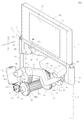
図1ないし図4に示す車載用電子機器1は、自動車のフロントガラスの手前に位置するダッシュボード2の内部に設置される。ダッシュボード2には上方に向けて開口する細長い形状の開口部3が設けられている。
The in-vehicle electronic device 1 shown in FIGS. 1 to 4 is installed inside a
機器本体10は、図2に示すように、ダッシュボード2の内部に格納された収納姿勢から、図4に示すように、ダッシュボード2の上方へ突出する突出姿勢との間で移動する。
As shown in FIG. 2, the device
機器本体10には表示パネル15が搭載されている。表示パネル15はカラー液晶表示パネルや有機エレクトロルミネッセンス表示パネルである。表示パネル15の表示画面15aは車両の内方(X1方向)に向けられている。X1方向は自動車の運転席と助手席の中間に対面する方向である。
A
ダッシュボード2の内部には、第1のガイド部である第1のガイド軸21と第2のガイド部である第2のガイド軸22が設けられている。第1のガイド軸21と第2のガイド軸22は共に金属製であり、断面が円形である。第1のガイド軸21と第2のガイド軸22は互いに平行であり、機器本体10の移動方向であるY1−Y2方向へ延びている。Y1−Y2方向はほぼ重力方向に向けられている。
Inside the
機器本体10の左側の下部に第1の軸受け部11が、右側の下部に第2の軸受け部12が一体に形成されている。第1の軸受け部11と第2の軸受け部12は、機器本体10の本体部と共に合成樹脂材料で形成されている。
A first bearing
図2などに示すように、第2の軸受け部12の内部の上端部にスラスト軸受13aが下端部にスラスト軸受13bが保持され固定されている。スラスト軸受13a,13bはメタル含油軸受であり、第2のガイド軸22の外周にほとんど隙間が無い状態で且つ最小の摩擦抵抗力を受ける状態で摺動自在に挿通されている。
As shown in FIG. 2 and the like, a thrust bearing 13a is held at the upper end portion inside the second bearing
第1の軸受け部11には軸受け穴14が開口している。軸受け穴14の内径は第1のガイド軸21の直径とほぼ同じかわずかに大きく形成されている。軸受け穴14は、第1のガイド軸21の外周部に摺動自在に挿通されている。
A
機器本体10は、第2のガイド軸22と2つのスラスト軸受13a,13bとの摺動部を基準としてY1−Y2方向へ移動自在である。スラスト軸受13a,13bが第2のガイド軸22を摺動し、第1の軸受け部11の軸受け穴14が第1のガイド軸21を最小の隙間で摺動するため、機器本体10はがたつきを発生することなく円滑に移動することができる。
The apparatus
ダッシュボード2の内部に第1の駆動アーム31と第2の駆動アーム41が設けられている。図1に示すように、第1の駆動アーム31は機器本体10の移動領域よりも内側(X1側)に位置し、第2の駆動アーム41は機器本体10の移動領域よりも外側(X2側)に位置している。第1の駆動アーム31と第2の駆動アーム41は、共に合成樹脂材料または軽金属材料で形成されている。
A
ダッシュボード2の内部には図示しない支持板が設けられ、支持板に第1の支持軸33が固定されている。第1の支持軸33は第1のガイド軸21に接近した位置に設けられている。第1の駆動アーム31の基部31aに軸受け部32が一体に形成されており、軸受け部32が第1の支持軸33に回動自在に支持されている。
A support plate (not shown) is provided inside the
図2ないし図4に示すように、第1の駆動アーム31の先部31bは第2のガイド軸22に接近する位置まで延びている。第1の駆動アーム31の先部31bにアーム側連結軸34が固定されている。機器本体10には、第2の軸受け部12の内側に駆動支持部16が一体に形成されており、この駆動支持部16に本体側連結軸35が固定されている。
As shown in FIGS. 2 to 4, the
駆動機構30には、第1の連結リンク36が設けられている。第1の連結リンク36は金属板または合成樹脂板で形成されている。第1の連結リンク36と第1の駆動アーム31の先部31bは、アーム側連結軸34の軸芯を中心として回動自在に連結されている。駆動支持部16と第1の連結リンク36は、本体側連結軸35の軸芯を中心として回動自在に連結されている。
The
第1の支持軸33の軸芯ならびにアーム側連結軸34の軸芯と本体側連結軸35の軸芯は互いに平行であり、それぞれの軸芯は前後方向(X1−X2方向)に延びている。すなわち、それぞれの軸芯は機器本体10の移動方向(Y1−Y2方向)と直交する向きに延びている。
The axis of the
ダッシュボード2の内部では、機器本体10よりも外側(X2側)に第2の支持軸43が固定されている。図2ないし図4に示すように、第2の支持軸43は第2のガイド軸22に接近した位置に設けられている。第2の駆動アーム41の基部41aに軸受け部42が一体に形成されており、軸受け部42が第2の支持軸43に回動自在に支持されている。
Inside the
第2の駆動アーム41の先部41bは第1のガイド軸21に接近する位置まで延びている。第2の駆動アーム41の先部41bにアーム側連結軸44が固定されている。機器本体10には、第1の軸受け部11の内側に駆動支持部17が一体に形成されており、この駆動支持部17に本体側連結軸45が固定されている。
The
第2の連結リンク46は金属板または合成樹脂板で形成されている。第2の連結リンク46と第2の駆動アーム41の先部41bは、アーム側連結軸44の軸芯を中心として回動自在に連結されている。駆動支持部17と第2の連結リンク46は、本体側連結軸45の軸芯を中心として回動自在に連結されている。
The
第2の支持軸43の軸芯ならびにアーム側連結軸44の軸芯と本体側連結軸45の軸芯は互いに平行であり、それぞれの軸芯は前後方向(X1−X2方向)に延びている。すなわち、それぞれの軸芯は機器本体10の移動方向(Y1−Y2方向)と直交する向きに延びている。
The axis of the
ダッシュボード2の内部には、第1の駆動アーム31と第2の駆動アーム41を互いに同期させて回動させる回動駆動部50が設けられている。
Inside the
図1に示すように、回転駆動部50では、機器本体10よりも内側(X1側)に駆動モータ51が設けられている。駆動モータ51は、低速で大トルクを発生するモータであり、供給電力を変化させることで回転数を可変する制御が可能である。駆動モータ51の出力軸にはウオーム歯車52が固定されている。
As shown in FIG. 1, the
図1に示すように、回転駆動部50には、機器本体10の移動領域よりも内側(X1側)に、ギヤ支持軸53が固定されており、このギヤ支持軸53に複合歯車54が回転自在に支持されている。複合歯車54は入力側歯車54aと出力側歯車54bが一体に形成されている。入力側歯車54aのピッチ円半径は、出力側歯車54bのピッチ円半径よりも大きい。前記ウオーム歯車52は入力側歯車54aと噛み合っている。
As shown in FIG. 1, a
機器本体10の移動領域よりも下側(Y1側)に、ギヤ支持軸55が設けられ、このギヤ支持軸55に複合歯車56が回転自在に支持されている。複合歯車56は減速歯車56aと連絡歯車56bとが一体に形成されている。減速歯車56aは、出力側歯車54bに噛み合っている。減速歯車56aのピッチ円半径は、出力側歯車54bのピッチ円半径よりも大きく、複合歯車54の回転数が減速されて複合歯車56に伝達される。
A
連絡歯車56bは、前後方向(X1−X2方向)に長く延びる平歯車である。第1の駆動アーム31の基部31aに扇歯車37が一体に形成されている。扇歯車37の歯部37aは、連絡歯車56bの内側(X1側)の端部と噛み合っている。
The connecting
機器本体10の移動領域よりも外側(X2側)にギヤ支持軸57が固定されて設けられており(図3参照)、このギヤ支持軸57に中間歯車58が回転自在に支持されている。図1に示すように中間歯車58は、それぞれは同じ半径のピッチ円を有する2枚の分離歯車58a,58bで構成されている。分離歯車58a,58bは互いに独立して回転できるように支持されている。図4に示すように、分離歯車58a,58bに形成された開口部58c内に圧縮コイルばね59が収納されており、分離歯車58aと分離歯車58bは、互いに逆回りとなるように付勢されている。この分離歯車58a,58bが連絡歯車56bの外側(X2側)の端部に噛み合っている。前記圧縮コイルばね59の付勢力によって、連絡歯車56bと中間歯車58との噛み合い部にバックラッシュが発生することがない。
A
第2の駆動アーム41の基部41aに扇歯車47が一体に形成されている。この扇歯車47の歯部47aが、前記中間歯車58の外側(X2側)の端部と噛み合っている。
A
次に、車載用電子機器1の動作について説明する。
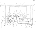
図2に示すように、機器本体10が使用されていないときは、第1の駆動アーム31が時計方向へ回動させられて、第1の連結リンク36によって右側の本体側連結軸35が下方(Y1方向)へ移動させられている。また、第2の駆動アーム41が反時計方向へ回動させられて、第2の連結リンク46によって左側の本体側連結軸45が下方(Y1方向)へ移動させられている。
Next, the operation of the in-vehicle electronic device 1 will be described.
As shown in FIG. 2, when the device
その結果、機器本体10が、第1のガイド軸21と第2のガイド軸22に案内されて、下方へ移動させられ、機器本体10がダッシュボード2の内部に格納された収納姿勢となっている。
As a result, the device
機器本体10が使用されるときは、図示しない操作装置が操作されて、駆動モータ51が始動させられる。駆動モータ51の回転力はウオーム歯車52から複合歯車54,56に伝達される。複合歯車56の連絡歯車56bの回動力が扇歯車37に伝達されて、第1の駆動アーム31が反時計方向へ回動させられる。同時に、連絡歯車56bの回転力が中間歯車58を介して扇歯車47に伝達されて、第2の駆動アーム41が時計方向へ回動させられる。
When the apparatus
図2、図3、図4に順に示すように、第1の駆動アーム31が反時計方向へ回動すると、先部31bのアーム側連結軸34の回動力が第1の連結リンク36を介して本体側連結軸35に与えられて、機器本体10の右側の駆動支持部16が持ち上げられる。同時に、第2の駆動アーム41の時計方向への回動力が、アーム側連結軸44から第2の連結リンク46を介して本体側連結軸45に与えられ、機器本体10の左側の駆動支持部17が持ち上げられる。
As shown in FIGS. 2, 3, and 4 in order, when the
その結果、機器本体10は第1のガイド軸21と第2のガイド軸22に案内されてY2方向へ移動する。図4に示すように機器本体10が開口部3を通過してダッシュボード2の上方へ移動して停止する。図4に示すように機器本体10が突出姿勢で停止すると、表示パネル15の表示画面15aを運転席や助手席から目視可能となる。
As a result, the apparatus
図2に示すように、機器本体10がY1側の移動終端で停止して収納姿勢となっているとき、第1の駆動アーム31の先部31bに設けられたアーム側連結軸34の軸芯が、本体側連結軸35の軸芯のほぼ真上に位置し、アーム側連結軸34の軸芯と本体側連結軸35の軸芯とが、機器本体10の移動方向であるY1−Y2方向に沿って並んでいる。すなわち、第1の連結リンク36のアーム側連結軸34の軸芯と本体側連結軸35の軸芯とを結ぶリンク中心線L3がY1−Y2方向とほぼ平行になる。ここでの平行とは、幾何学的に厳密な平行に対して±10度以下の範囲を意味し、さらに好ましくは±5度以下の範囲を意味している。
As shown in FIG. 2, the axis of the arm-
同様に、第2の駆動アーム41の先部41bに設けられたアーム側連結軸44の軸芯が、左側の本体側連結軸45の軸芯のほぼ真上に位置し、アーム側連結軸44の軸芯と本体側連結軸45の軸芯とが、機器本体10の移動方向であるY1−Y2方向に沿って並んでいる。
Similarly, the axis of the arm
したがって、図2の状態から第1の駆動アーム31と第2の駆動アーム41が回動し始めるときに、本体側連結軸35,45に対して上向き(Y2方向)の力の成分が作用し、左右方向の分力が発生しにくくなり、収納姿勢の機器本体10が滑らかに上昇し始める。また、図2の状態で上下方向(Y1−Y2方向)の振動が与えられたときに、第2の連結リンク36と第2の連結リンク46を回動させようとする分力が抑制されることになり、外部振動が与えられたときに機器本体10や駆動機構30のがたつきが発生しにくくなる。
Therefore, when the
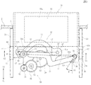
図3では、第1の支持軸33の軸芯と第1の駆動アーム31の先部31aに設けられたアーム側連結軸34の軸芯とを結ぶアーム中心線L1がほぼ水平姿勢であり、第2の支持軸43の軸芯と第2の駆動アーム41の先部41bのアーム側連結軸44の軸芯とを結ぶアーム中心線L2もほぼ水平姿勢である。
In FIG. 3, the arm center line L1 connecting the axis of the
このとき、アーム側連結軸34の軸芯が、本体側連結軸35の軸芯よりも第1の支持軸33から遠ざかる位置関係となる。このような位置関係となるように前記アーム中心線L1の長さと第1の連結リンク36の長さとが設定されることにより、第1の駆動アーム31の反時計方向への回動力によって、機器本体10が、図2に示す収納姿勢から図4に示す突出姿勢まで移動できるようになる。
At this time, the axial center of the arm
図3に示すように、第1の連結リンク36のアーム側連結軸34の軸芯と本体側連結軸35の軸芯とを結ぶリンク中心線L3が、機器本体10の移動方向であるY1−Y2方向に対して最も傾いたときの傾き角度θは45度以下であり、好ましくは40度以下である。
As shown in FIG. 3, a link center line L3 connecting the axis of the arm
第1の駆動アーム31が回動するときの第1の連結リンク36の傾き角度θを前記範囲とすることにより、第1の駆動アーム31の回動力が、本体側連結軸35に対して作用するY1−Y2方向の駆動力の成分の比率が大きくなる。すなわち、第1の駆動アーム31が回動するときの第1の連結リンク36の回動量が小さくなり、第1の駆動アーム31の回動力が、第1の連結リンク36の回動力に消費される比率を小さくでき、機器本体10をY1−Y2方向へ滑らかに移動させることができ、第1の連結リンク36の回動によるがたつきを抑制できるようになる。
By setting the inclination angle θ of the
また、図3に示すように、第2の駆動アーム41が回動するときの、第2の連結リンク46の動作ならびにアーム側連結軸44と本体側連結軸45との位置関係は、第1の連結リンク36の動作ならびにアーム側連結軸34と本体側連結軸35との位置関係と同じである。
Further, as shown in FIG. 3, the operation of the second connecting
図4に示すように、機器本体10がY2側の移動終端に至って突出姿勢になったとき、第1の駆動アーム31に設けられたアーム側連結軸34の軸芯が、本体側連結軸35の軸芯のほぼ真上に位置し、アーム側連結軸34の軸芯と本体側連結軸35の軸芯とが、機器本体10の移動方向であるY1−Y2方向に沿って並んでいる。そして、リンク中心線L3がY1−Y2方向とほぼ平行になる。また、第2の駆動アーム41に設けられたアーム連結軸44の軸芯も本体側連結軸45の軸芯の上方に位置している。
As shown in FIG. 4, when the device
よって、機器本体が図4に示す突出姿勢に向けて移動するとき、また突出姿勢から収納姿勢に向けて下向きに移動するときに、第1の駆動アーム31と第2の駆動アーム41から機器本体40に対してY1−Y2方向に沿う移動力が効果的に伝達され、機器本体40が滑らかに移動できるようになる。また、図4の状態においても、上下方向(Y1−Y2方向)の振動が与えられたときに、第2の連結リンク36と第2の連結リンク46を回動させようとする分力が抑制され、機器本体10や駆動機構30のがたつきが発生しにくくなる。
Therefore, when the device main body moves toward the protruding posture shown in FIG. 4 and when it moves downward from the protruding posture toward the storage posture, the device main body is moved from the
駆動機構30では、第1の連結リンク36と第2の連結リンク46が回動することによって、第1の駆動アーム31と第2の駆動アーム41の回転運動が機器本体10のY1−Y2方向への直線運動に変換される。第1の駆動アーム31ならびに第2の駆動アーム41と機器本体10との連結部の動作が、全て軸を支点とした回転運動となるため、機器本体10が滑らかに移動でき、また動力伝達部のがたつきも発生しにくくなる。
In the
特に、従来のように、長穴と軸との摺動構造を有していないため、機器本体10の動きが非常に滑らかになり、また長穴と軸とのがたつきによる駆動機構30の振動音も発生しにくくなる。
In particular, since there is no sliding structure between the long hole and the shaft as in the prior art, the movement of the device
駆動モータ51は、低回転数で大トルクのモータであり、回転数を制御できるものであるため、駆動モータ51の回転数を制御することによって、機器本体10が図2に示す収納姿勢から図4に示す突出姿勢へ移動するときの移動速度変化を滑らかにして移動状態の品位を高く保つことができる。
The
図1に示すように、第1の駆動アーム31と第1の連結リンク36が、機器本体10の移動領域よりも内側(X1側)に位置し、第2の駆動アーム41と第2の連結リンク46が、機器本体10の移動領域よりも外側(X2側)に位置している。機器本体10の移動領域を挟む両側ならびに第1と第2のガイド軸21,22の案内部を挟んだ両側において、第1の連結リンク36と第2の連結リンク46から機器本体10に移動力が与えられるため、移動中の機器本体10にX1−X2方向へ倒れようとするモーメントが作用しにくくなる。これによって、さらに機器本体10の動きが滑らかになる。
As shown in FIG. 1, the
図2に示すように、この駆動機構30では、第1の支持軸33とアーム側連結軸34の軸芯間の距離、すなわち第1の駆動アーム31のアーム中心線L1の長さと、第2の支持軸43とアーム側連結軸44の軸芯間の距離、すなわち第2の駆動アーム41のアーム中心線L2の長さとが相違している。アーム中心線L1がアーム中心線L2よりも長くなっている。また、第1の駆動アーム31に設けられた扇歯車37のピッチ円の半径R1と、第2の駆動アーム41に設けられた扇歯車47のピッチ円の半径R2とが相違し、半径R1が半径R2よりも長くなっている。
As shown in FIG. 2, in the
アーム中心線L1,L2の長さの比と、ピッチ円の半径R1,R2の長さの比を調整することで、図3に示すように機器本体10が移動しているときの、右側の駆動支持部16に与えられるY1−Y2方向の速度成分V1と、左側の駆動支持部17に与えられるY1−Y2方向の速度成分V2とを同じ速度に設定することができる。
By adjusting the ratio of the lengths of the arm center lines L1 and L2 and the ratio of the lengths of the pitch circle radii R1 and R2, the right side of the device
また、アーム中心線L1,L2の長さの比と、ピッチ円の半径R1,R2の長さの比を調整して、右側の速度成分V1と左側の速度成分V2にわずかな差を持たせることができる。この場合に、機器本体10に対して図3における右方向または左方向への移動付勢力を与えることができ、ガイド軸21,22と軸受け部11,12とのがたつきを完全に解消することが可能になる。
Further, the ratio of the lengths of the arm center lines L1 and L2 and the ratio of the lengths of the radiuses R1 and R2 of the pitch circle are adjusted to give a slight difference between the right speed component V1 and the left speed component V2. be able to. In this case, it is possible to apply a moving urging force in the right direction or the left direction in FIG. 3 to the device
本発明は、上記実施の形態に限られず、以下の変更が可能である。
まず、アーム中心線L1の長さとアーム中心線L2の長さを同じにし、ピッチ円の半径R1とピッチ円の半径R2を同じにすることにより、さらに左右のバランスがとれた機器本体10の移動を実現することも可能である。
The present invention is not limited to the above-described embodiment, and the following modifications are possible.
First, by making the length of the arm center line L1 and the length of the arm center line L2 the same, and making the radius R1 of the pitch circle and the radius R2 of the pitch circle the same, the movement of the
また、駆動アームを一対設けずに、1個の駆動アームのみによって機器本体を移動させることが可能である。 Further, it is possible to move the device main body by only one drive arm without providing a pair of drive arms.
さらに、機器本体10の移動方向は重力方向(上下方向)に限られず、重力方向に対して斜めの向きや、水平の向きに移動させることも可能である。また、機器本体10は表示パネルを備えているものに限られず、各種メディアを搭載したメディア駆動装置や操作装置などであってもよい。
Furthermore, the moving direction of the apparatus
1 車載用電子機器
2 ダッシュボード
3 開口部
10 機器本体
11 第1の軸受け部
12 第2の軸受け部
13a,13b スラスト軸受
15 表示パネル
21 第1のガイド軸
22 第2のガイド軸
30 駆動機構
31 第1の駆動アーム
32 第1の支持軸
34 アーム側連結軸
35 本体側連結軸
36 第1の連結リンク
41 第2の駆動アーム
43 第2の支持軸
44 アーム側連結軸
45 本体側連結軸
46 第2の連結リンク
50 回転駆動部
L1,L2 アーム中心線
DESCRIPTION OF SYMBOLS 1 In-vehicle
Claims (7)
前記駆動機構は、基部が支持軸を支点として回動自在に支持された駆動アームと、前記駆動アームを回動させる回動駆動部と、前記駆動アームの先部と前記機器本体とを連結する連結リンクとを有しており、
前記連結リンクと前記駆動アームとがアーム側連結軸を支点として回動自在に連結され、前記連結リンクと前記機器本体とが本体側連結軸を支点として回動自在に連結されていることを特徴とする車載用電子機器。 In an in-vehicle electronic device having a guide portion, a device main body that reciprocates along the guide portion, and a drive mechanism that reciprocates the device main body,
The drive mechanism connects a drive arm whose base portion is rotatably supported with a support shaft as a fulcrum, a rotation drive unit that rotates the drive arm, a tip portion of the drive arm, and the device main body. A link and
The connection link and the drive arm are rotatably connected with an arm side connection shaft as a fulcrum, and the connection link and the device main body are rotatably connected with a body side connection shaft as a fulcrum. In-vehicle electronic equipment.
Priority Applications (3)
| Application Number | Priority Date | Filing Date | Title |
|---|---|---|---|
| JP2012214316A JP5950779B2 (en) | 2012-09-27 | 2012-09-27 | Automotive electronics |
| US13/950,030 US9320161B2 (en) | 2012-09-27 | 2013-07-24 | On-vehicle electronic device |
| EP13185547.0A EP2712767B1 (en) | 2012-09-27 | 2013-09-23 | On-vehicle electronic device |
Applications Claiming Priority (1)
| Application Number | Priority Date | Filing Date | Title |
|---|---|---|---|
| JP2012214316A JP5950779B2 (en) | 2012-09-27 | 2012-09-27 | Automotive electronics |
Publications (2)
| Publication Number | Publication Date |
|---|---|
| JP2014069578A true JP2014069578A (en) | 2014-04-21 |
| JP5950779B2 JP5950779B2 (en) | 2016-07-13 |
Family
ID=49301275
Family Applications (1)
| Application Number | Title | Priority Date | Filing Date |
|---|---|---|---|
| JP2012214316A Active JP5950779B2 (en) | 2012-09-27 | 2012-09-27 | Automotive electronics |
Country Status (3)
| Country | Link |
|---|---|
| US (1) | US9320161B2 (en) |
| EP (1) | EP2712767B1 (en) |
| JP (1) | JP5950779B2 (en) |
Cited By (1)
| Publication number | Priority date | Publication date | Assignee | Title |
|---|---|---|---|---|
| JP2015225174A (en) * | 2014-05-27 | 2015-12-14 | アルパイン株式会社 | On-vehicle electronic device |
Families Citing this family (7)
| Publication number | Priority date | Publication date | Assignee | Title |
|---|---|---|---|---|
| DE102015012890B4 (en) * | 2015-10-06 | 2017-11-16 | Audi Ag | Adjustment device for a motor vehicle |
| JP6510386B2 (en) * | 2015-11-13 | 2019-05-08 | アルパイン株式会社 | Automotive electronics |
| JP6817148B2 (en) * | 2017-06-02 | 2021-01-20 | アルパイン株式会社 | In-vehicle electronic device |
| US10625688B2 (en) * | 2017-11-06 | 2020-04-21 | Global Ip Holdings, Llc | Assembly capable of deploying an electronic device having a display screen in a vehicle |
| KR102340790B1 (en) * | 2020-01-08 | 2021-12-16 | 엘지전자 주식회사 | Display apparatus for vehicle |
| KR102986740B1 (en) * | 2021-01-06 | 2026-07-03 | 현대자동차주식회사 | Apparatus for Opening of the Display unit |
| KR20240059332A (en) * | 2022-10-27 | 2024-05-07 | 현대모비스 주식회사 | Moving display device and vehicle using the same |
Citations (3)
| Publication number | Priority date | Publication date | Assignee | Title |
|---|---|---|---|---|
| JPH08295180A (en) * | 1995-04-28 | 1996-11-12 | Toyota Autom Loom Works Ltd | Attachment support device for carrier device |
| JPH1038593A (en) * | 1996-07-17 | 1998-02-13 | Mitsubishi Motors Corp | Navigation device |
| US20110141702A1 (en) * | 2008-05-14 | 2011-06-16 | Robert Wolfgang Kissel | Display Device |
Family Cites Families (4)
| Publication number | Priority date | Publication date | Assignee | Title |
|---|---|---|---|---|
| JPH0141972Y2 (en) | 1985-06-12 | 1989-12-11 | ||
| DE69305186T2 (en) * | 1992-01-08 | 1997-05-22 | Pioneer Electronic Corp | System for moving a television set mounted in a motor vehicle |
| JPH10333595A (en) | 1997-05-29 | 1998-12-18 | Nec Kansai Ltd | Storable display device |
| DE102006042693A1 (en) * | 2006-09-12 | 2008-03-27 | Siemens Ag | Board monitor device |
-
2012
- 2012-09-27 JP JP2012214316A patent/JP5950779B2/en active Active
-
2013
- 2013-07-24 US US13/950,030 patent/US9320161B2/en active Active
- 2013-09-23 EP EP13185547.0A patent/EP2712767B1/en active Active
Patent Citations (3)
| Publication number | Priority date | Publication date | Assignee | Title |
|---|---|---|---|---|
| JPH08295180A (en) * | 1995-04-28 | 1996-11-12 | Toyota Autom Loom Works Ltd | Attachment support device for carrier device |
| JPH1038593A (en) * | 1996-07-17 | 1998-02-13 | Mitsubishi Motors Corp | Navigation device |
| US20110141702A1 (en) * | 2008-05-14 | 2011-06-16 | Robert Wolfgang Kissel | Display Device |
Cited By (1)
| Publication number | Priority date | Publication date | Assignee | Title |
|---|---|---|---|---|
| JP2015225174A (en) * | 2014-05-27 | 2015-12-14 | アルパイン株式会社 | On-vehicle electronic device |
Also Published As
| Publication number | Publication date |
|---|---|
| EP2712767A1 (en) | 2014-04-02 |
| US20140085787A1 (en) | 2014-03-27 |
| EP2712767B1 (en) | 2016-01-13 |
| JP5950779B2 (en) | 2016-07-13 |
| US9320161B2 (en) | 2016-04-19 |
Similar Documents
| Publication | Publication Date | Title |
|---|---|---|
| JP5950779B2 (en) | Automotive electronics | |
| JP6153854B2 (en) | Display device | |
| JP6575855B2 (en) | In-vehicle combiner lifting device and in-vehicle head-up display device | |
| CN108327649B (en) | Supporting device and vehicle for in-vehicle display terminal | |
| CN101163613B (en) | Display device | |
| JP2014231238A (en) | Display device | |
| CN112937460B (en) | Display mobile device | |
| US20090038422A1 (en) | Device for adjusting angle of monitor for vehicle | |
| JP2018002050A (en) | Head-up display | |
| JP2013159297A (en) | Head-up display device | |
| JP2009291290A (en) | Movable decoration device of game machine | |
| KR20090124780A (en) | The electronic lower tilt steering apparatus for vehicle | |
| CN112009384B (en) | A kind of adjustment mechanism and vehicle for display terminal | |
| JP7023580B2 (en) | Guidance drive device | |
| JP5930936B2 (en) | Automotive electronics | |
| CN107000645A (en) | Motion, outside lens device and vehicle | |
| JP4532260B2 (en) | Drive mechanism for retractable monitor | |
| JP6840439B2 (en) | In-vehicle display device | |
| JP2022062069A (en) | Display device using guide drive unit | |
| JP2007314057A (en) | In-vehicle display unit holding housing | |
| JP2005153849A (en) | Steering device | |
| JP4251971B2 (en) | Automotive electronics | |
| JP2006070490A (en) | Automatic door opening and closing device | |
| CN222474059U (en) | Adjusting mechanism of central control screen and vehicle | |
| CN217778524U (en) | Gesture adjustment assembly, vehicle-mounted display terminal and vehicle |
Legal Events
| Date | Code | Title | Description |
|---|---|---|---|
| A621 | Written request for application examination |
Free format text: JAPANESE INTERMEDIATE CODE: A621 Effective date: 20150227 |
|
| A131 | Notification of reasons for refusal |
Free format text: JAPANESE INTERMEDIATE CODE: A131 Effective date: 20151117 |
|
| A977 | Report on retrieval |
Free format text: JAPANESE INTERMEDIATE CODE: A971007 Effective date: 20151119 |
|
| A521 | Request for written amendment filed |
Free format text: JAPANESE INTERMEDIATE CODE: A523 Effective date: 20151228 |
|
| TRDD | Decision of grant or rejection written | ||
| A01 | Written decision to grant a patent or to grant a registration (utility model) |
Free format text: JAPANESE INTERMEDIATE CODE: A01 Effective date: 20160607 |
|
| A61 | First payment of annual fees (during grant procedure) |
Free format text: JAPANESE INTERMEDIATE CODE: A61 Effective date: 20160607 |
|
| R150 | Certificate of patent or registration of utility model |
Ref document number: 5950779 Country of ref document: JP Free format text: JAPANESE INTERMEDIATE CODE: R150 |