JP2014101902A - Clutch mechanism - Google Patents
Clutch mechanism Download PDFInfo
- Publication number
- JP2014101902A JP2014101902A JP2012252465A JP2012252465A JP2014101902A JP 2014101902 A JP2014101902 A JP 2014101902A JP 2012252465 A JP2012252465 A JP 2012252465A JP 2012252465 A JP2012252465 A JP 2012252465A JP 2014101902 A JP2014101902 A JP 2014101902A
- Authority
- JP
- Japan
- Prior art keywords
- magnetic
- attraction
- magnetic circuit
- armature
- pulley
- Prior art date
- Legal status (The legal status is an assumption and is not a legal conclusion. Google has not performed a legal analysis and makes no representation as to the accuracy of the status listed.)
- Pending
Links
Images


Classifications
-
- F—MECHANICAL ENGINEERING; LIGHTING; HEATING; WEAPONS; BLASTING
- F16—ENGINEERING ELEMENTS AND UNITS; GENERAL MEASURES FOR PRODUCING AND MAINTAINING EFFECTIVE FUNCTIONING OF MACHINES OR INSTALLATIONS; THERMAL INSULATION IN GENERAL
- F16D—COUPLINGS FOR TRANSMITTING ROTATION; CLUTCHES; BRAKES
- F16D27/00—Magnetically- or electrically- actuated clutches; Control or electric circuits therefor
- F16D27/10—Magnetically- or electrically- actuated clutches; Control or electric circuits therefor with an electromagnet not rotating with a clutching member, i.e. without collecting rings
- F16D27/108—Magnetically- or electrically- actuated clutches; Control or electric circuits therefor with an electromagnet not rotating with a clutching member, i.e. without collecting rings with axially movable clutching members
- F16D27/112—Magnetically- or electrically- actuated clutches; Control or electric circuits therefor with an electromagnet not rotating with a clutching member, i.e. without collecting rings with axially movable clutching members with flat friction surfaces, e.g. discs
-
- F—MECHANICAL ENGINEERING; LIGHTING; HEATING; WEAPONS; BLASTING
- F16—ENGINEERING ELEMENTS AND UNITS; GENERAL MEASURES FOR PRODUCING AND MAINTAINING EFFECTIVE FUNCTIONING OF MACHINES OR INSTALLATIONS; THERMAL INSULATION IN GENERAL
- F16D—COUPLINGS FOR TRANSMITTING ROTATION; CLUTCHES; BRAKES
- F16D13/00—Friction clutches
- F16D13/76—Friction clutches specially adapted to incorporate with other transmission parts, i.e. at least one of the clutch parts also having another function, e.g. being the disc of a pulley
-
- F—MECHANICAL ENGINEERING; LIGHTING; HEATING; WEAPONS; BLASTING
- F16—ENGINEERING ELEMENTS AND UNITS; GENERAL MEASURES FOR PRODUCING AND MAINTAINING EFFECTIVE FUNCTIONING OF MACHINES OR INSTALLATIONS; THERMAL INSULATION IN GENERAL
- F16D—COUPLINGS FOR TRANSMITTING ROTATION; CLUTCHES; BRAKES
- F16D27/00—Magnetically- or electrically- actuated clutches; Control or electric circuits therefor
- F16D27/004—Magnetically- or electrically- actuated clutches; Control or electric circuits therefor with permanent magnets combined with electromagnets
-
- F—MECHANICAL ENGINEERING; LIGHTING; HEATING; WEAPONS; BLASTING
- F16—ENGINEERING ELEMENTS AND UNITS; GENERAL MEASURES FOR PRODUCING AND MAINTAINING EFFECTIVE FUNCTIONING OF MACHINES OR INSTALLATIONS; THERMAL INSULATION IN GENERAL
- F16D—COUPLINGS FOR TRANSMITTING ROTATION; CLUTCHES; BRAKES
- F16D27/00—Magnetically- or electrically- actuated clutches; Control or electric circuits therefor
- F16D27/14—Details
-
- F—MECHANICAL ENGINEERING; LIGHTING; HEATING; WEAPONS; BLASTING
- F16—ENGINEERING ELEMENTS AND UNITS; GENERAL MEASURES FOR PRODUCING AND MAINTAINING EFFECTIVE FUNCTIONING OF MACHINES OR INSTALLATIONS; THERMAL INSULATION IN GENERAL
- F16D—COUPLINGS FOR TRANSMITTING ROTATION; CLUTCHES; BRAKES
- F16D27/00—Magnetically- or electrically- actuated clutches; Control or electric circuits therefor
- F16D2027/008—Details relating to the magnetic circuit, or to the shape of the clutch parts to achieve a certain magnetic path
Landscapes
- Engineering & Computer Science (AREA)
- General Engineering & Computer Science (AREA)
- Mechanical Engineering (AREA)
- Physics & Mathematics (AREA)
- Electromagnetism (AREA)
- Compressors, Vaccum Pumps And Other Relevant Systems (AREA)
- Pulleys (AREA)
Abstract
【課題】クラッチ機構20の体格を小さくして消費電力を小さくする。
【解決手段】クラッチ機構20では、アーマチァ40の非磁性部90、91とプーリ30の非磁性部70、71、72とは、回転軸2aの径方向にオフセットされている。このため、吸引用磁気回路MCaでは、磁束が外側円筒部31および内側円筒部32の間にてアーマチァ40の非磁性部90、91とプーリ30の非磁性部70、71、72とを避けて通過する。これにより、アーマチァ40とプーリ30との間の境界を6回通過することになる。吸引用磁気回路MCaの極数が大きくなる。永久磁石51の体格を小さくすることができる。このため、クラッチ機構20の体格を小さくなる。これに伴い、コイル部53a、53bの断面積を大きくすることにより、電磁コイル53の消費電力を小さくすることができる。
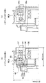
【選択図】図1To reduce power consumption by reducing the size of a clutch mechanism.
In a clutch mechanism 20, nonmagnetic portions 90, 91 of an armature 40 and nonmagnetic portions 70, 71, 72 of a pulley 30 are offset in the radial direction of a rotary shaft 2a. Therefore, in the magnetic circuit for attraction MCa, the magnetic flux avoids the nonmagnetic portions 90 and 91 of the armature 40 and the nonmagnetic portions 70, 71 and 72 of the pulley 30 between the outer cylindrical portion 31 and the inner cylindrical portion 32. pass. As a result, the boundary between the armature 40 and the pulley 30 passes six times. The number of poles of the magnetic circuit for attraction MCa increases. The physique of the permanent magnet 51 can be made small. For this reason, the physique of the clutch mechanism 20 becomes small. In connection with this, the power consumption of the electromagnetic coil 53 can be made small by enlarging the cross-sectional area of coil part 53a, 53b.
[Selection] Figure 1
Description
本発明は、永久磁石を用いたクラッチ機構に関するものである。 The present invention relates to a clutch mechanism using a permanent magnet.
現在、市場に多く流通している電磁石式のクラッチ機構では、エンジンから回転駆動力が伝達されて回転するプーリと、回転駆動力を圧縮機に伝えるアーマチャとを備え、永久磁石を用いない構成で、アーマチャに対してプーリを吸引させる吸引磁力を電磁コイルから発生させる構成になっているものがある。 Currently, the electromagnet clutch mechanism that is widely distributed in the market is equipped with a pulley that rotates when the rotational driving force is transmitted from the engine, and an armature that transmits the rotational driving force to the compressor, and does not use a permanent magnet. There is a configuration in which an attractive magnetic force for attracting a pulley to an armature is generated from an electromagnetic coil.
このものにおいては、プーリとアーマチャと連結されているときには、エンジンから回転駆動力がプーリおよびアーマチャを通して圧縮機に伝達される。プーリとアーマチャとが離れているときには、エンジンから圧縮機への回転駆動力の伝達が遮断される。このように構成されるクラッチ機構では、アーマチャとプーリとが連結状態であるときには、継続的に電磁コイルに通電して電磁コイルから吸引磁力を発生させる必要がある。 In this device, when the pulley and the armature are connected, the rotational driving force is transmitted from the engine to the compressor through the pulley and the armature. When the pulley and the armature are separated from each other, transmission of the rotational driving force from the engine to the compressor is interrupted. In the clutch mechanism configured as described above, when the armature and the pulley are in a connected state, it is necessary to continuously energize the electromagnetic coil to generate an attractive magnetic force from the electromagnetic coil.
これに対して、永久磁石を用いて吸引磁力を発生させるクラッチ機構として、プーリと、アーマチャと、第1、第2のコイル部からなる電磁コイルと、第1、第2のコイル部の間に挟持されている永久磁石と、磁性材から構成されて圧縮機の回転軸の軸線方向に移動可能になっている可動部材とを備えるものがある(特許文献1参照)。 On the other hand, as a clutch mechanism for generating an attractive magnetic force using a permanent magnet, a pulley, an armature, an electromagnetic coil composed of first and second coil parts, and a first and second coil part. Some include a permanent magnet that is sandwiched and a movable member that is made of a magnetic material and is movable in the axial direction of the rotation shaft of the compressor (see Patent Document 1).
このものにおいては、プーリ、アーマチャ、および永久磁石によって吸引用磁気回路MCaを構成している。吸引用磁気回路MCaから発生する磁力は、プーリに対してアーマチャを吸引する吸引力として作用する。永久磁石は、吸引用磁気回路MCaとは異なる非吸引用磁気回路MCbを構成する。アーマチャとプーリとの間を離す方向に弾性力を作用させる弾性部材が配置されている。 In this device, a pulling magnetic circuit MCa is constituted by a pulley, an armature, and a permanent magnet. The magnetic force generated from the magnetic circuit for attraction MCa acts as an attractive force for attracting the armature to the pulley. The permanent magnet constitutes a non-attraction magnetic circuit MCb different from the attraction magnetic circuit MCa. An elastic member that applies an elastic force in a direction separating the armature and the pulley is disposed.
プーリとアーマチャと連結されているときには、プーリおよびアーマチャの間が離れているときよりも、吸引用磁気回路MCaの磁気抵抗が小さくなる位置(以下、第1の位置という)に、可動部材が位置する。 When the pulley and the armature are connected, the movable member is positioned at a position where the magnetic resistance of the attraction magnetic circuit MCa becomes smaller (hereinafter referred to as the first position) than when the pulley and the armature are separated from each other. To do.
プーリとアーマチャとの間が離れているときには、プーリおよびアーマチャが連結しているときよりも、非吸引用磁気回路MCbの磁気抵抗が小さくなる位置(以下、第2の位置という)に、可動部材が位置する。 When the pulley and the armature are separated from each other, the movable member is located at a position where the magnetic resistance of the non-attraction magnetic circuit MCb is smaller (hereinafter referred to as a second position) than when the pulley and the armature are connected. Is located.
そして、プーリおよびアーマチャが連結しているときに、第1、第2のコイル部に対して第1方向に電流を流すと、吸引用磁気回路MCaから生じる磁力を第1のコイル部から生じる電磁力により減少させ、かつ非吸引用磁気回路MCbから生じる磁力を第2のコイル部から生じる電磁力により増加させる。これにより、吸引用磁気回路MCaから生じる磁力よりも非吸引用磁気回路MCbから生じる磁力の方が大きくなる。これに伴い、非吸引用磁気回路MCbから生じる磁力によって、第1の位置側から第2の位置側に可動部材が移動する。 When the pulley and the armature are connected, if a current is passed through the first and second coil portions in the first direction, the magnetic force generated from the attraction magnetic circuit MCa is generated from the first coil portion. The magnetic force generated from the non-attraction magnetic circuit MCb is increased by the electromagnetic force generated from the second coil portion. Thereby, the magnetic force generated from the non-attraction magnetic circuit MCb becomes larger than the magnetic force generated from the attraction magnetic circuit MCa. Along with this, the movable member moves from the first position side to the second position side by the magnetic force generated from the non-attraction magnetic circuit MCb.
このとき、吸引用磁気回路MCaからの吸引磁力の方が弾性部材の弾性力よりも小さくなる。このため、弾性部材の弾性力によってプーリおよびアーマチャの間が連結状態から分離状態に変化することになる。すなわち、クラッチ機構がON状態からOFF状態に移行することになる。 At this time, the attractive magnetic force from the attractive magnetic circuit MCa is smaller than the elastic force of the elastic member. For this reason, between the pulley and the armature is changed from the connected state to the separated state by the elastic force of the elastic member. That is, the clutch mechanism shifts from the ON state to the OFF state.
次に、プーリおよびアーマチャの間が離れているときに第1、第2のコイル部に対して第1方向とは逆方向に電流を流すと、吸引用磁気回路MCaから生じる磁力を第1のコイル部から生じる電磁力により増加させ、かつ非吸引用磁気回路MCbから生じる磁力を第2のコイル部から生じる電磁力により減少させる。これにより、吸引用磁気回路MCaから生じる磁力の方が非吸引用磁気回路MCbから生じる磁力よりも大きくなる。これに伴い、吸引用磁気回路MCaから生じる磁力によって、第2の位置側から第1の位置側に可動部材が移動する。 Next, when a current is applied to the first and second coil portions in a direction opposite to the first direction when the pulley and the armature are separated from each other, the magnetic force generated from the attractive magnetic circuit MCa is The magnetic force generated from the non-attraction magnetic circuit MCb is increased by the electromagnetic force generated from the coil portion, and the magnetic force generated from the second coil portion is decreased. Thereby, the magnetic force generated from the attraction magnetic circuit MCa is larger than the magnetic force generated from the non-attraction magnetic circuit MCb. Along with this, the movable member moves from the second position side to the first position side by the magnetic force generated from the attraction magnetic circuit MCa.
このとき、吸引用磁気回路MCaからの吸引磁力の方が弾性部材の弾性力よりも大きくなる。このため、吸引用磁気回路MCaからの吸引磁力によって、プーリおよびアーマチャの間が分離状態から連結状態に変化することになる。すなわち、クラッチ機構がOFF状態からON状態に移行することになる。 At this time, the attractive magnetic force from the attractive magnetic circuit MCa is larger than the elastic force of the elastic member. For this reason, the pulley and the armature change from the separated state to the connected state by the attractive magnetic force from the attractive magnetic circuit MCa. That is, the clutch mechanism shifts from the OFF state to the ON state.
このように、プーリおよびアーマチャの間を連結状態から分離状態に変化させるとき、或いは、プーリおよびアーマチャの間を分離状態から連結状態に変化させるときにだけ、第1、第2のコイル部に電流を流すことになる。このため、上記従来型の電磁石式のクラッチ機構に比べて、大幅な省電力化を達成することを可能としている。 Thus, only when the pulley and the armature are changed from the connected state to the separated state, or when the pulley and the armature are changed from the separated state to the connected state, a current is supplied to the first and second coil portions. Will flow. For this reason, it is possible to achieve a significant power saving as compared with the conventional electromagnetic clutch mechanism.
本発明者等は、上記特許文献1のクラッチ機構について、小型化に着目し、詳細に磁場解析を進めたところ、次のような問題点が分かった。
The inventors of the present invention focused on downsizing the clutch mechanism of
まず、上記電磁石式のクラッチ機構は、アーマチャおよびプーリの間の連結状態を維持する吸引力を電磁コイルから発生させる構成になっているのに対し、上記特許文献1のクラッチ機構では、永久磁石を用いて上記吸引力を発生させる構成になっている。このため、上記特許文献1のクラッチ機構において、上記電磁石式のクラッチ機構と同一の伝達トルクを達成するためには、体格が大きい永久磁石が必要となるので、クラッチ機構自体の軸方向寸法(軸長)が大きくなることは明らかである。
First, the electromagnet clutch mechanism is configured to generate an attractive force from the electromagnetic coil to maintain the connection between the armature and the pulley, whereas the clutch mechanism disclosed in
これに加えて、体格が大きい永久磁石を用いると、非吸引用磁気回路MCbにおいて流れる磁束量も多くなり、可動部材を移動させるために瞬間的とはいえ大きな電力を第1、第2のコイル部に対して与える必要があるといった実用上の問題が明らかになった。 In addition to this, when a permanent magnet having a large physique is used, the amount of magnetic flux flowing in the non-attraction magnetic circuit MCb increases, and a large amount of electric power is instantaneously generated in order to move the movable member. The practical problem that it was necessary to give to the department became clear.
例えば、図10は、上記電磁石式の電磁クラッチの設計例であり、ステータ56の圧縮機への取付け当接面Haとアーマチャ40の端面との間の距離が36mm、プーリ40の呼び径がφ115の例である。
For example, FIG. 10 shows a design example of the electromagnetic type electromagnetic clutch. The distance between the attachment contact surface Ha of the
本例において磁場解析を行うと、電磁コイル53Aに与える起磁力を700AT(アンペアターン=電流×巻数)とすると、プーリ(ロータ)30に対するアーマチャ40の吸引力は4300Nとなった。また、本図の電磁コイル53Aの体格では700ATの起磁力を発生させるためには、30Wの電力の消費を要する。
When the magnetic field analysis is performed in this example, when the magnetomotive force applied to the
図11は、図10と同じ大きさの摩擦面(プーリ30とアーマチャ40との接触面)を備え、上記特許文献1の発明の考え方を踏襲した自己保持型のクラッチ機構において同じく4300Nの吸引力が発生するように設計した例である。この場合、磁力の大きいネオジム磁石(最大エネルギー積40MGOe)を用いても永久磁石の使用量は92g(内径φ73.4、外径φ82.2、軸方向長さ11.25)となった。
FIG. 11 is a self-holding clutch mechanism having a friction surface (contact surface between the
このような上記自己保持型のクラッチ機構では、クラッチ機構がOFF状態であるときに非吸引用磁気回路MCbから吸引用磁気回路MCa側に磁束が漏れないようにすることが必要である。このため、非吸引用磁気回路MCbを構成するステータ56の円筒部56a、壁部56b、可動部材51の板厚は、磁気飽和が発生しない厚さが必要である。
In such a self-holding clutch mechanism, it is necessary to prevent magnetic flux from leaking from the non-attraction magnetic circuit MCb to the attraction magnetic circuit MCa when the clutch mechanism is in the OFF state. For this reason, the plate | board thickness of the
ここで、図10の電磁石式の電磁クラッチは、そもそも、非吸引用磁気回路MCbを有する構成になっていない。このため、図10の上記電磁石式の電磁クラッチのステータ56の内側円筒部56c、壁部56b、外周円筒部56dの板厚に比べて、図11の自己保持型のクラッチ機構におけるステータ56の円筒部56a、壁部56b、可動部材55の板厚を、大きくする必要がある。
Here, the electromagnetic electromagnetic clutch shown in FIG. 10 does not have a configuration having the non-attraction magnetic circuit MCb in the first place. Therefore, the cylinder of the
以上の理由により、上記自己保持型のクラッチ機構では、上記電磁石式の電磁クラッチに対して、体格、重量を増やすことなしに、同じ吸引力、即ち同じ伝達トルクを得ることは叶わないという問題がある。 For the reasons described above, the self-holding clutch mechanism has a problem that the same attractive force, that is, the same transmission torque cannot be obtained without increasing the physique and weight with respect to the electromagnetic type electromagnetic clutch. is there.
さらに、本発明者の検討によれば、クラッチ機構をOFF状態からON状態とするためには第1、第2のコイル部53a、53bには、それぞれ700ATの起磁力を与える必要があることも磁場解析で明らかになった。
Further, according to the study of the present inventor, it is necessary to apply a magnetomotive force of 700 AT to the first and
しかしながら、図11と図10を比較して明らかなように、図11の電磁コイル53の体格は図10の電磁コイル53Aの体格に比べて小さい。例えば、図11の電磁コイル53a(或いは、53b)の断面積Saと図10の電磁コイル53Aの断面積Sbとの比率(=(Sa/Sb)×100%)は約25%になる。
However, as apparent from comparison between FIG. 11 and FIG. 10, the physique of the
ここで、電磁コイル53から一定の起磁力を発生させる場合において、電磁コイル53の断面積が小さくなるほど、電磁コイル53を構成するコイル線の線径を大きくし、かつ巻数を少なくすることが必要になる。コイル線の線径が大きくなるほど、単位断面積あたりの抵抗値は小さくなるので、コイル線に流れる電流は大きくなる。このため、電磁コイル53の断面積が小さくなるほど、電磁コイル53で消費される消費電力が大きくなる。
Here, in the case of generating a constant magnetomotive force from the
例えば、図10の電磁コイル53Aが消費電力30Wで700ATの起磁力を発生できるのに対して、図11の第1、第2コイル部53a、53bのそれぞれで120Wの消費電力となる。僅かな時間(例えば、0.2秒程度)とはいえ120Wの電力を第1、第2コイル部53a、53bに供給するためには、ハーネス、コネクタなどの各種の電子部品の電流容量を大きくすることが必要となるという問題がある。
For example, the
本発明は上記点に鑑みて、少ない使用量の永久磁石で、クラッチ機構の体格を小さくするとともに、電磁コイルの消費電力も小さくすることを可能にしたクラッチ機構を提供することを目的とする。 An object of the present invention is to provide a clutch mechanism capable of reducing the size of the clutch mechanism and reducing the power consumption of the electromagnetic coil with a small amount of permanent magnets.
上記目的を達成するため、請求項1に記載の発明では、駆動源からの回転駆動力によって回転する駆動側回転体(30)と、
前記駆動側回転体に連結されることによって前記回転駆動力が伝達される従動側回転体(40)と、
前記駆動側回転体と前記従動側回転体とを連結させる吸引磁力を発生させる吸引用磁気回路(MCa)を、前記駆動側回転体および前記従動側回転体とともに、構成し、かつ前記吸引用磁気回路とは異なる非吸引用磁気回路(MCb)を構成する永久磁石(51)と、
前記吸引用磁気回路から生じる磁力と前記非吸引用磁気回路から生じる磁力とを変化させる電磁力を発生させる電磁コイル(53)と、
磁性材で形成されて、かつ変位可能に構成される部材であって、前記駆動側回転体と前記従動側回転体とが連結しているときには、前記駆動側回転体および前記従動側回転体の間が離れているときよりも、前記吸引用磁気回路の磁気抵抗が小さくなる位置(以下、第1の位置という)に位置し、前記駆動側回転体および前記従動側回転体の間が離れているときには、前記駆動側回転体と前記従動側回転体が連結しているときよりも、前記非吸引用磁気回路の磁気抵抗が小さくなる位置(以下、第2の位置という)に位置する可動部材(55)と、
前記吸引用磁気回路から生じる磁力が前記非吸引用磁気回路から生じる磁力よりも大きくなるように前記電磁コイルに通電することにより、前記吸引用磁気回路から生じる磁力によって前記第2の位置側から前記第1の位置側に前記可動部材を変位させる第1の制御手段(6)と、
前記非吸引用磁気回路から生じる磁力が前記吸引用磁気回路から生じる磁力よりも大きくなるように前記電磁コイルに通電することにより、前記非吸引用磁気回路から生じる磁力によって前記第1の位置側から前記第2の位置側に前記可動部材を変位させる第2の制御手段(6)と、を備え、
前記吸引用磁気回路を通過する磁束が前記駆動側回転体および前記従動側回転体の間の境界を通過する回数を極数としたときに、前記吸引用磁気回路の極数が6以上になるように前記駆動側回転体と前記従動側回転体とが構成されていることを特徴とする。
In order to achieve the above object, in the first aspect of the present invention, a driving side rotating body (30) that rotates by a rotational driving force from a driving source;
A driven side rotator (40) to which the rotational driving force is transmitted by being connected to the drive side rotator;
An attraction magnetic circuit (MCa) for generating an attractive magnetic force for connecting the driving side rotating body and the driven side rotating body is configured together with the driving side rotating body and the driven side rotating body, and the attraction magnetic field A permanent magnet (51) constituting a non-attraction magnetic circuit (MCb) different from the circuit;
An electromagnetic coil (53) for generating an electromagnetic force for changing a magnetic force generated from the magnetic circuit for attraction and a magnetic force generated from the magnetic circuit for non-attraction;
A member formed of a magnetic material and configured to be displaceable, and when the driving side rotating body and the driven side rotating body are connected, the driving side rotating body and the driven side rotating body It is located at a position where the magnetic resistance of the magnetic circuit for attraction becomes smaller (hereinafter referred to as the first position) than when the gap is separated, and the drive side rotary body and the driven side rotary body are separated from each other. The movable member is located at a position where the magnetic resistance of the non-attraction magnetic circuit is smaller than that when the driving side rotating body and the driven side rotating body are connected (hereinafter referred to as a second position). (55)
By energizing the electromagnetic coil such that the magnetic force generated from the attraction magnetic circuit is larger than the magnetic force generated from the non-attraction magnetic circuit, the magnetic force generated from the attraction magnetic circuit causes the second position side to First control means (6) for displacing the movable member toward the first position;
By energizing the electromagnetic coil such that the magnetic force generated from the non-attraction magnetic circuit is larger than the magnetic force generated from the attraction magnetic circuit, the magnetic force generated from the non-attraction magnetic circuit causes the magnetic force from the first position side. Second control means (6) for displacing the movable member on the second position side,
The number of poles of the attraction magnetic circuit is 6 or more when the number of times the magnetic flux passing through the attraction magnetic circuit passes through the boundary between the driving side rotating body and the driven side rotating body is the pole number. As described above, the drive-side rotator and the driven-side rotator are configured as described above.
ここで、請求項1に記載の発明と特許文献1のクラッチ機構とで同一の吸引磁力を発生させる場合において、極数が多いと吸引用磁気回路を流れる磁束は少なくなり、永久磁石の使用量を少なくなる。すなわち、永久磁石の体格を小さくすることができる。このため、クラッチ機構の軸方向寸法を小さくしつつ、電磁コイルの断面積を大きくすることができる。
Here, in the case where the same attractive magnetic force is generated by the invention according to
電磁コイルから一定の起磁力を発生させる際に、電磁コイルの断面積が大きくなるほど、電磁コイルを構成するコイル線の線径を小さくし、かつ巻数を大きくすることが可能になる。 When a constant magnetomotive force is generated from the electromagnetic coil, the larger the cross-sectional area of the electromagnetic coil, the smaller the wire diameter of the coil wire constituting the electromagnetic coil and the larger the number of turns.
そして、コイル線の線径を小さくするほど、コイル線の単位断面積あたりの抵抗値が大きくなるので、電磁コイルに流れる電流が小さくなる。このため、電磁コイルの消費電力を小さくすることができる。このことにより、電磁コイルの消費電力は、電磁コイルの断面積が大きくなるほど、小さくなる。 And, as the wire diameter of the coil wire is reduced, the resistance value per unit cross-sectional area of the coil wire is increased, so that the current flowing through the electromagnetic coil is reduced. For this reason, the power consumption of the electromagnetic coil can be reduced. As a result, the power consumption of the electromagnetic coil decreases as the cross-sectional area of the electromagnetic coil increases.
これに加えて、吸引用磁気回路を流れる磁束量が少なくなることにより、クラッチ機構をOFF状態からON状態に変化させるのに必要な電磁コイルにおける起磁力も小さくすることができる。 In addition to this, since the amount of magnetic flux flowing through the attraction magnetic circuit is reduced, the magnetomotive force in the electromagnetic coil required to change the clutch mechanism from the OFF state to the ON state can also be reduced.
ここで、クラッチ機構をOFF状態からON状態に変化させるのに必要な電磁コイルの消費電力は、電磁コイルの起磁力の2乗に比例する。このため、起磁力が小さくなるほど、電磁コイルの消費電力を下げることができる。 Here, the power consumption of the electromagnetic coil required to change the clutch mechanism from the OFF state to the ON state is proportional to the square of the magnetomotive force of the electromagnetic coil. For this reason, the power consumption of an electromagnetic coil can be reduced, so that a magnetomotive force becomes small.
以上により、電磁コイルの断面積を大きくし、かつ起磁力も小さくすることにより、電磁コイルの消費電力を大幅に小さくすることができる。したがって、少ない使用量の永久磁石で、従来同等の伝達トルクを達成しつつ、クラッチ機構の体格を小さくするとともに、電磁コイルの消費電力も小さくすることが可能になる。 As described above, the power consumption of the electromagnetic coil can be significantly reduced by increasing the cross-sectional area of the electromagnetic coil and reducing the magnetomotive force. Therefore, it is possible to reduce the physique of the clutch mechanism and reduce the power consumption of the electromagnetic coil while achieving the same transmission torque as before with a small amount of permanent magnets.
なお、クラッチ機構のOFF状態とは、駆動側回転体および従動側回転体の間が離れている状態のことである。クラッチ機構のON状態とは、駆動側回転体および従動側回転体の間が連結している状態のことである。 In addition, the OFF state of the clutch mechanism is a state where the driving side rotating body and the driven side rotating body are separated from each other. The ON state of the clutch mechanism is a state where the driving side rotating body and the driven side rotating body are connected.
なお、この欄および特許請求の範囲で記載した各手段の括弧内の符号は、後述する実施形態に記載の具体的手段との対応関係を示すものである。 In addition, the code | symbol in the bracket | parenthesis of each means described in this column and the claim shows the correspondence with the specific means as described in embodiment mentioned later.
以下、本発明の実施形態について図に基づいて説明する。なお、以下の各実施形態相互において、互いに同一もしくは均等である部分には、説明の簡略化を図るべく、図中、同一符号を付してある。 Hereinafter, embodiments of the present invention will be described with reference to the drawings. In the following embodiments, parts that are the same or equivalent to each other are given the same reference numerals in the drawings in order to simplify the description.
(第1実施形態)
図1は、本実施形態のクラッチ機構20が適用された車両用空調装置の冷凍サイクル装置1の全体構成図である。
(First embodiment)
FIG. 1 is an overall configuration diagram of a
冷凍サイクル装置1は、圧縮機2、放熱器3、膨張弁4、および、蒸発器5を接続したものである。圧縮機2は、冷媒を吸入して圧縮する。放熱器3は、圧縮機2の吐出冷媒を放熱させる。膨張弁4は、放熱器3から流出される冷媒を減圧膨張させる。蒸発器5は、膨張弁4にて減圧された冷媒を蒸発させて吸熱作用を発揮させる。
The
圧縮機2は、車両のエンジンルームに設置されている。圧縮機2は、走行用駆動源としてのエンジン10からクラッチ機構20を介して与えられる回転駆動力によって圧縮機構を駆動させることにより、蒸発器5から冷媒を吸入して圧縮する。
The
なお、圧縮機構としては、吐出容量が固定された固定容量型圧縮機構、あるいは、外部からの制御信号によって吐出容量を調整可能に構成された可変容量型圧縮機構のいずれを採用してもよい。 As the compression mechanism, either a fixed displacement compression mechanism with a fixed discharge capacity or a variable displacement compression mechanism configured to be able to adjust the discharge capacity by an external control signal may be employed.
本実施形態のクラッチ機構20は、圧縮機2に連結されたプーリ一体型のクラッチ機構である。クラッチ機構20は、エンジン側プーリ11からVベルト12を介して与えられるエンジン10の回転駆動力を圧縮機2に伝達する。エンジン側プーリ11は、エンジン10の回転駆動軸に連結されているものである。
The
クラッチ機構20は、プーリ30およびアーマチァ40を備える。プーリ30はエンジン10からのVベルト12を介して与えられる回転駆動力によって回転する駆動側回転体を構成する。アーマチァ40は、圧縮機2の回転軸2aに連結された従動側回転体を構成する。クラッチ機構20は、プーリ30とアーマチァ40との間を連結あるいは分離することで、エンジン10から圧縮機2への回転駆動力の伝達を断続するものである。
The
つまり、クラッチ機構20がプーリ30とアーマチァ40とを連結すると、エンジン10の回転駆動力が圧縮機2に伝達されて、冷凍サイクル装置1が作動する。一方、クラッチ機構20がプーリ30とアーマチァ40とを離すと、エンジン10の回転駆動力が圧縮機2に伝達されることはなく、冷凍サイクル装置1も作動しない。
That is, when the
次に、本実施形態のクラッチ機構20の詳細構成について図2、図3、図4を用いて説明する。
Next, the detailed structure of the
図2は、クラッチ機構20の軸方向断面図である。この軸方向断面図は、クラッチ機構20において圧縮機2の回転軸2aの軸線を含んで、かつ軸線に沿う断面図である。図3は図2のIII−III断面図である。図2では、プーリ30とアーマチァ40とを連結させた状態を図示している。図3は後述するハブ42の図示を省略している。図4はプーリ30単体を圧縮機2の回転軸2aの軸線方向一端側から視た図、図5はアーマチァ40単体を軸線方向一端側から視た図である。
FIG. 2 is an axial sectional view of the
図2および図3に示すように、クラッチ機構20は、プーリ30、アーマチァ40とともに、ステータ50を備える。
As shown in FIGS. 2 and 3, the
まず、プーリ30は、外側円筒部31、内側円筒部32、および、端面部33を有している。
First, the
外側円筒部31は、圧縮機2の回転軸2aの軸線(図2中一点鎖線)を中心線とする円筒状に形成されている。外側円筒部31は、磁性材(例えば、鉄)にて形成されている。外側円筒部31の外周側には、Vベルト12が掛けられるV溝(具体的には、ポリV溝)が形成されている。
The outer
内側円筒部32は、外側円筒部31の内周側に配置されて圧縮機2の回転軸2aの軸線を軸線とする円筒状に形成されている。内側円筒部32は、磁性材(例えば、鉄)一体にて形成されている。
The inner
内側円筒部32の内周側には、ボールベアリング34の外側レースが固定されている。ボールベアリング34は、圧縮機2の外殻を形成するハウジング2cに対して、回転軸2aの軸線を中心線としてプーリ30を回転自在に固定するものである。そのため、ボールベアリング34の内側レースは、圧縮機2のハウジング2cに対してスナップリング100等の固定部材によって固定されている。ボールベアリング34の内側レースは、圧縮機2のハウジング2cに設けられたハウジングボス部2bに対して径方向外側に配置されている。ハウジングボス部2bは、圧縮機2の回転軸2aの軸線を中心線とする円筒状に形成されている。
An outer race of a
端面部33は、外側円筒部31回転軸方向一端側と内側円筒部32の回転軸方向一端側との間に亘って形成されている。
The
端面部33は、回転軸2aの軸心を中心とするリング状に形成されている。具体的には、端面部33は、図4に示すように、リング部材60、61、62、63を備える。
The
リング部材60、61、62、63は、回転軸2aの軸心を中心するリング状に形成されている。リング部材60、61、62、63は、回転軸2aの径方向にオフセットして配置されている。
The
本実施形態のリング部材60は、リング部材61に対して内周側に配置されている。リング部材61は、リング部材62に対して内周側に配置されている。リング部材62は、リング部材63に対して内周側に配置されている。そして、リング部材60、61、62、63は、それぞれ、磁性材(例えば、鉄)によって形成されている。
The
リング部材60、61の間には、リング部材60、61を接続する6つのブリッジ部材67が設けられている。6つのブリッジ部材67は、非磁性の金属材料からなるもので、回転軸2aの軸心を中心として60度ずつオフセットして配置されている。
Between the
このことにより、リング部材60、61の間には、回転軸2aの軸心を中心とする円弧状の空隙33bが6つ設けられることになる。つまり、6つの空隙33bおよび6つのブリッジ部材67からなる非磁性部70がリング部材60、61の間に設けられることになる。非磁性部70は、回転軸2aの軸心を中心とするリング状に形成されている。
As a result, between the
リング部材61、62の間には、リング部材61、62を接続する6つのブリッジ部材66が設けられている。6つのブリッジ部材66は、非磁性の金属材料からなるもので、回転軸2aの軸心を中心として60度ずつオフセットして配置されている。
Between the
このことにより、リング部材61、62の間には、回転軸2aの軸心を中心とする円弧状の空隙33cが6つ設けられることになる。つまり、6つの空隙33cおよび6つのブリッジ部材66からなる非磁性部71がリング部材61、62の間に設けられることになる。非磁性部71は、回転軸2aの軸心を中心とするリング状に形成されている。
As a result, between the
リング部材62、63の間には、リング部材62、63を接続する6つのブリッジ部材65が設けられている。6つのブリッジ部材65は、非磁性の金属材料からなるもので、回転軸2aの軸心を中心として60度ずつオフセットして配置されている。
Between the
このことにより、リング部材62、63の間には、回転軸2aの軸心を中心とする円弧状の空隙33aが6つ設けられることになる。つまり、6つの空隙33bおよび6つのブリッジ部材65からなる非磁性部72がリング部材62、63の間に設けられることになる。非磁性部72は、回転軸2aの軸心を中心とするリング状に形成されている
本実施形態では、プーリ30は、一体に成形されたものである。このため、外側円筒部31と端面部33のリング部材63とが繋がっている。端面部33のリング部材60と内側円筒部32とが繋がっている。そして、外側円筒部31、端面部33のリング部材60、61、62、63、および内側円筒部32は、後述するように、吸引用磁気回路MCaを構成する。
As a result, between the
また、端面部33の他端側面は、プーリ30とアーマチァ40が連結された際に、アーマチァ40と接触する摩擦面を形成している。そこで、本実施形態では、端面部33の非磁性部72(空隙33a)の表面側には、端面部33の摩擦係数を増加させるための摩擦部材35が配置されている。摩擦部材35は、回転軸2aの軸心を中心とするリング状に形成されている。摩擦部材35は、非磁性材で形成されており、具体的には、アルミナを樹脂で固めたものや、金属粉末(例えば、アルミニウム粉末)の焼結材を採用できる。
Further, the other end side surface of the
アーマチァ40は、プーリ30の端面部33に対して軸線方向他端側に配置されている。アーマチァ40は、後述するように吸引用磁気回路MCaを構成する。具体的には、アーマチァ40は、回転軸2aに直交する方向に広がるとともに、中央部にその表裏を貫通する貫通穴が形成された円板状部材である。アーマチァ40の回転中心は、回転軸2aの軸心に一致している。
The
アーマチァ40は、図5に示すように、リング部材80、81、82から構成されている。リング部材80、81、82は、回転軸2aの軸心を中心するリング状に形成されている。リング部材80、81、82は、回転軸2aの径方向にオフセットして配置されている。
As shown in FIG. 5, the
本実施形態のリング部材80は、リング部材81に対して内周側に配置されている。リング部材81は、リング部材82に対して内周側に配置されている。そして、リング部材80、81、82は、それぞれ、磁性材(例えば、鉄)によって形成されている。
The
リング部材80、81の間には、リング部材80、81の間を接続する4つのブリッジ部材83が設けられている。4つのブリッジ部材83は、非磁性の金属材からなるもので、回転軸2aの軸心を中心として45度ずつオフセットして配置されている。
Between the
このことにより、リング部材80、81の間には、回転軸2aの軸心を中心とする円弧状の空隙40bが4つ設けられることになる。つまり、4つの空隙40bおよび4つのブリッジ部材83からなる非磁性部90がリング部材80、81の間に設けられることになる。非磁性部90は、回転軸2aの軸心を中心とするリング状に形成されている
リング部材81、82の間には、リング部材81、82の間を接続するブリッジ部材84が4つ設けられている。4つのブリッジ部材84は、非磁性の金属材からなるもので、回転軸2aの軸心を中心として45度ずつオフセットして配置されている。
As a result, four
このことにより、リング部材81、82の間には、回転軸2aの軸心を中心とする円弧状の空隙40aが4つ設けられることになる。つまり、4つの空隙40aおよび4つのブリッジ部材84からなる非磁性部91がリング部材81、82の間に設けられることになる。非磁性部91は、回転軸2aの軸心を中心とするリング状に形成されている。
As a result, four arc-shaped
このように構成されるアーマチァ40の非磁性部90、91とプーリ30の非磁性部70、71、72とは、それぞれ回転軸2aの径方向にオフセットされている。具体的には、プーリ30の非磁性部70、71の間にアーマチァ40の非磁性部90が配置されている。プーリ30の非磁性部71、72の間にアーマチァ40の非磁性部91が配置されている。
The
ここで、アーマチァ40の一端側の平面は、プーリ30の端面部33に対向している。プーリ30とアーマチァ40が連結された際に、プーリ30と接触する摩擦面を形成している。アーマチァ40の他端側には、略円盤状のハブ42が配置されている。
Here, the flat surface on one end side of the
ハブ42は、アーマチァ40と圧縮機2の回転軸2aとを連結する連結部材を構成している。具体的には、ハブ42は、回転軸方向に延びる円筒部42aと、この円筒部42aの他端側から回転軸に対する垂直方向に広がるフランジ部42bとを備えている。
The
ハブ42とアーマチァ40との間には、回転軸に対する垂直方向に広がる板バネ45が配置されている。板バネ45は、ハブ42のフランジ部42bに対してリベット41aによって固定されている。
Between the
ここで、板バネ45は、リベット41bによってアーマチァ40に固定されている。板バネ45は、ハブ42に対してアーマチァ40がプーリ30から離れる方向に弾性力を作用させている。この弾性力により、プーリ30とアーマチァ40が離れた状態では、ハブ42に連結されたアーマチァ40とプーリ30の端面部33との間に予め定めた所定間隔の隙間M3(後述する図6参照)が形成される。
Here, the
ハブ42は、その円筒部42aが圧縮機2の回転軸2aに対してボルト44によって締め付けられることによって固定されている。なお、ハブ42と圧縮機2の回転軸2aとの固定には、スプライン(セレーション)あるいはキー溝などの締結手段を用いてもよい。
The
これにより、アーマチァ40、ハブ42、板バネ45、圧縮機2の回転軸2aが連結され、プーリ30とアーマチァ40が連結されると、アーマチァ40、ハブ42、板バネ45、圧縮機2の回転軸2aがプーリ30とともに回転する。
As a result, the
また、ステータ50は、永久磁石51、電磁コイル53、ストッパ部54、可動部材55、ステータハウジング56、およびヨーク57を備えるステータアッセンブリである。
The
永久磁石51は、圧縮機2の回転軸2aの軸線を中心とする円環状に形成されている。永久磁石51はその外周側がN極を構成し、永久磁石51の内周側がS極を構成している。永久磁石51は、後述するように、吸引用磁気回路MCaおよび非吸引用磁気回路MCbを発生させる。
The
本実施形態では、永久磁石51の材料として、ネオジウムやサマリウムコバルトを採用することができる。そして、永久磁石51、電磁コイル53、ストッパ部54、ステータハウジング56、およびヨーク57が接着剤により固定されて、円環状に形成されている構造体52を構成する。
In the present embodiment, neodymium or samarium cobalt can be used as the material of the
電磁コイル53は、第1のコイル部53aおよび第2のコイル部53bを備える。本実施形態の第1、第2のコイル部53a、53bは、直列に接続されている。第1のコイル部53aは、圧縮機2の回転軸2aの軸線を中心とする円環状に形成されている。そして、第2のコイル部53bは、圧縮機2の回転軸2aの軸線を中心とする円環状に形成されている。
The
第1のコイル部53aは、永久磁石51に対して軸線方向他端側に配置されている。第2のコイル部53bは、永久磁石51に対して軸線方向一端側に配置されている。つまり、永久磁石51は、第1、第2のコイル部53a、53bの間に挟まれている。
The
本実施形態の第1、第2のコイル部53a、53bは、銅やアルミ等からなるコイル線が例えば樹脂成形されたスプールに複列・複層に巻き付けることにより構成されている。
The first and
可動部材55は、電磁コイル53およびヨーク57に対して回転軸2aの径方向外側に配置されている。具体的には、可動部材55は、電磁コイル53およびヨーク57に対してクリアランスを介して配置されている。
The
可動部材55は、回転軸2aの軸線を中心とする円筒状に形成されている。可動部材55は、外側円筒部31に対して回転軸2aの径方向内側に配置されている。可動部材55と外側円筒部31との間には、隙間M2が形成されている。可動部材55は、電磁コイル53およびヨーク57に対して回転軸2aの軸方向(スラスト方向)に相対移動可能に構成されている。可動部材55は、磁性材(例えば、鉄)にて形成されている。
The
ここで、可動部材55の回転軸方向の全長は、構造体52の回転軸方向の全長よりも短く形成されている。これにより、可動部材55が、軸線方向他端側の位置(以下、第1の位置という)に位置する場合には、軸線方向一端側に空隙(エアギャップ)が形成される。空隙は、永久磁石51がプーリ30の端面部33の反対側に形成する非吸引用磁気回路MCbの磁気抵抗を増加させる。
Here, the total length of the
逆に、可動部材55が、軸線方向一端側の位置(第2の位置という)に位置する場合には、軸線方向他端側に空隙が形成される。空隙は、永久磁石51がプーリ30の端面部33側に形成する吸引用磁気回路MCaの磁気抵抗を増加させる。
Conversely, when the
このような可動部材55の軸線方向の移動によって、吸引用磁気回路MCaの磁気抵抗、および非吸引用磁気回路MCbの磁気抵抗をそれぞれ変化させることができる。
By such movement of the
ストッパ部54は、可動部材55および電磁コイル53の第1コイル部53aに対して軸線方向他端側に配置されている。ストッパ部54は、可動部材55を衝突させて軸線方向他端側への移動を停止させる。
The
ステータハウジング56は、筒部56a、および壁部56bを備える。筒部56aは、永久磁石51および電磁コイル53に対して回転軸2aの径方向内側に配置されている。筒部56aは、回転軸2aの軸心を中心とする円筒状に形成されている。壁部56bは、筒部56aの一端側から回転軸2aの径方向外側に広がる円環状に形成されている。筒部56aおよび壁部56bは、磁性材(例えば、鉄)により一体に形成され、吸引用磁気回路MCa、および非吸引用磁気回路MCbをそれぞれ構成する。
The
なお、ステータハウジング56の壁部56bには、電磁コイル53と制御装置6との間を接続する電線53cを貫通させる貫通穴56cが設けられている。
In addition, a through
本実施形態のステータハウジング56は、圧縮機2のハウジング2cに対してスナップリング101などの固定手段によって固定されている。ステータハウジング56は、上述の如く、構造体52を構成している。このため、構造体52は、圧縮機2のハウジング2cに固定されていることになる。そして、ステータハウジング56の筒部56aとプーリ30の内側円筒部32との間には隙間M1が設けられている。
The
ヨーク57は、第1、第2のコイル部53a、53bの間に配置されて、回転軸2aの軸心を中心とするリング状に形成されている。ヨーク57は、磁性材(例えば、鉄)により一体に形成され、吸引用磁気回路MCa、および非吸引用磁気回路MCbをそれぞれ構成する。
The
また、図1の制御装置6は、エアコンECU(電子制御装置)から出力される制御信号に基づいて、第1、第2の電磁コイル53a、53bへの通電を制御する。
The
次に、本実施形態のクラッチ機構20の作動について図6を参照して説明する。図6は、図2のB部の断面図を用いた説明図である。
Next, the operation of the
まず、図6(a)に示すように、プーリ30とアーマチァ40が連結された状態では、可動部材55が、軸線方向他端側の第1位置に位置している。
First, as shown in FIG. 6A, in a state where the
この際、永久磁石51によって形成される吸引用磁気回路MCaの磁気抵抗が、可動部材55が軸線方向一端側の第2位置に位置している場合よりも減少して、吸引用磁気回路MCaによって生じる磁力が大きくなっている。
At this time, the magnetic resistance of the attracting magnetic circuit MCa formed by the
吸引用磁気回路MCaは、図6(a)の太実線に示すように、ヨーク57→可動部材55→外側円筒部31→端面部33→アーマチァ40→端面部33→アーマチァ40→端面部33→アーマチァ40→端面部33→内側円筒部32→ステータハウジング56の筒部56a→永久磁石51の順で磁束が通過する磁気回路である。
As shown by a thick solid line in FIG. 6A, the magnetic circuit for attraction MCa includes a
具体的には、吸引用磁気回路MCaでは、磁束が外側円筒部31および内側円筒部32の間にてアーマチァ40の非磁性部90、91とプーリ30の非磁性部70、71、72とを避けて通過する。
Specifically, in the magnetic circuit for attraction MCa, the magnetic flux passes between the
すなわち、吸引用磁気回路MCaでは、磁束が外側円筒部31および内側円筒部32の間にてアーマチァ40のリング部材80、81、82とプーリ30のリング部材60、61、62、63とを通過する。このため、アーマチァ40とプーリ30との間の境界を6回通過することになる。
That is, in the magnetic circuit for attraction MCa, the magnetic flux passes between the
さらに、図6(a)の太実線に示す吸引用磁気回路MCaによって生じる磁力は、プーリ30とアーマチァ40とを連結させる吸引磁力となっている。
Furthermore, the magnetic force generated by the magnetic circuit for attraction MCa shown by the thick solid line in FIG. 6A is an attraction magnetic force that connects the
また、可動部材55が、軸線方向他端側の第1の位置に位置している場合には、可動部材55とステータプレート56の壁部56bとの間に空隙が形成される。
Further, when the
この空隙は、非吸引用磁気回路MCbの磁気抵抗を増加させ、非吸引用磁気回路MCbによって生じる磁力を減少させる。非吸引用磁気回路MCbは、永久磁石51によって形成されて、かつ吸引用磁気回路MCaとは異なる磁気回路である。非吸引用磁気回路MCbは、図6(a)の細破線に示すように、ヨーク57、可動部材55、ステータプレート56、および永久磁石51の順に磁束が通過する磁気回路である。非吸引用磁気回路MCbによって生じる磁力は、プーリ30とアーマチァ40とを連結させる吸引力として機能しない。
This air gap increases the magnetic resistance of the non-attraction magnetic circuit MCb and decreases the magnetic force generated by the non-attraction magnetic circuit MCb. The non-attraction magnetic circuit MCb is a magnetic circuit formed by the
さらに、可動部材55が、軸線方向他端側の第1の位置に位置している場合には、可動部材55が、軸線方向一端側の第2の位置に位置している場合に比べて、吸引用磁気回路MCaの磁束量が増加しているので、可動部材55は、軸線方向他端側の第1の位置側に維持される。
Further, when the
また、本実施形態では、板バネ45の弾性力が、可動部材55が軸線方向他端側の第1の位置に位置する場合の吸引用磁気回路MCaに生じる吸引磁力よりも小さくなるように設定されている。したがって、電磁コイル53に電力を供給しなくても、プーリ30とアーマチァ40が連結された状態が維持される。すなわち、エンジン10からの回転駆動力が圧縮機2へ伝達される。
In the present embodiment, the elastic force of the
次に、制御装置6が電磁コイル53に対して第1方向への通電を開始する。このとき、図6(b)に示すように、第1のコイル53aには紙面裏から紙面表に電流が流れ、かつ第2のコイル53bには紙面裏から紙面表に電流が流れる。このため、第1のコイル53aが、吸引用磁気回路MCaを通過する磁束量を減少させるとともに、第2のコイル53bが、非吸引用磁気回路MCbを通過する磁束量を増加させる。これにより、図6(b)の細実線で示す吸引用磁気回路MCaによって生じる吸引磁力よりも、図6(b)の太破線で示す非吸引用磁気回路MCbによって生じる磁力が強くなる。
Next, the
これに伴い、可動部材55が、非吸引用磁気回路MCbによって生じる磁力によって、軸線方向他端側の第1位置側から軸線方向一端側の第2位置側へ移動する。すなわち、永久磁石51から生じる磁力と第2のコイル53bから生じる電磁力とによって可動部材55が、第1位置側から第2位置側へ移動することになる。その後、制御装置6が電磁コイル53に対する通電を終了する。
Accordingly, the
このような可動部材55の移動に伴って、非吸引用磁気回路MCbの磁気抵抗が減少して、非吸引用磁気回路MCbを通過する磁束量が増加する。このため、図6(c)に示すように、可動部材55が軸線方向一端側の第2位置に維持されることになる。
As the
ここで、可動部材55が第2位置に位置するときには、可動部材55とプーリ30の端面部33との間に空隙が形成される。この空隙によって、プーリ30とアーマチァ40が連結されているときよりも、吸引用磁気回路MCaの磁気抵抗が増加する。このため、吸引用磁気回路MCaから生じる吸引磁力が減少する。その結果、板バネ45による弾性力が上記吸引磁力よりも大きくなる。このため、電磁コイル53に電力を供給しなくても、板バネ45による弾性力によって、プーリ30とアーマチァ40が離れた状態が維持される。これにより、エンジン10からの回転駆動力は圧縮機2へ伝達されない。
Here, when the
次に、制御装置6が電磁コイル53に対して第2方向への通電を開始する。第2方向とは、上記第1方向とは逆の方向のことである。このため、図6(d)に示すように、第1のコイル部53aには紙面表から紙面裏に電流が流れ、かつ第2のコイル部53bには紙面表から紙面裏に電流が流れる。このため、第1のコイル部53aが、吸引用磁気回路MCaを通過する磁束量を増加させるとともに、第2のコイル部53bが、非吸引用磁気回路MCbを通過する磁束量を減少させる電磁力を発生させる。これにより、非吸引用磁気回路MCbによって生じる磁力よりも、吸引用磁気回路MCaによって生じる吸引磁力が強くなる。
Next, the
これに伴い、吸引用磁気回路MCaによって生じる吸引磁力によって可動部材55が軸線方向一端側の第2位置側から軸線方向他端側の第1位置側へ移動する。すなわち、永久磁石51から生じる磁力と第1のコイル53aから生じる電磁力とによって可動部材55が第2位置側から第1位置側へ移動することになる。つまり、可動部材55が図6(a)に示す状態に戻ることになる。その後、制御装置6が電磁コイル53に対する通電を終了する。
Accordingly, the
このような可動部材55の移動に伴って、吸引用磁気回路MCaの磁気抵抗が減少して、吸引用磁気回路MCaの磁束量が増加する。その結果、上記吸引磁力が板バネ45による弾性力よりも大きくなり、プーリ30とアーマチァ40が連結される。すなわち、エンジン10からの回転駆動力が圧縮機2へ伝達される。
As the
以上説明した本実施形態によれば、プーリ30とアーマチァ40とが連結しているときには、プーリ30およびアーマチァ40の間が離れているときよりも、吸引用磁気回路MCaの磁気抵抗が小さくなる第1の位置に可動部材55が位置する。プーリ30およびアーマチァ40の間が離れているときには、プーリ30とアーマチァ40とが連結しているときよりも、非吸引用磁気回路MCbの磁気抵抗が小さくなる第2の位置に可動部材55が位置する。制御装置6は、吸引用磁気回路MCaから生じる磁力が非吸引用磁気回路MCbから生じる磁力よりも大きくなるように電磁コイル53に通電することにより、吸引用磁気回路MCaから生じる磁力によって第2の位置側から第1の位置側に可動部材55を変位させる。制御装置6は、非吸引用磁気回路MCbから生じる磁力が吸引用磁気回路MCaから生じる磁力よりも大きくなるように電磁コイル53に通電することにより、非吸引用磁気回路MCbから生じる磁力によって第1の位置側から第2の位置側に可動部材55を変位させる。
According to the present embodiment described above, when the
ここで、アーマチァ40の非磁性部90、91とプーリ30の非磁性部70、71、72とは、それぞれ回転軸2aの径方向にオフセットされている。このため、吸引用磁気回路MCaでは、磁束が外側円筒部31および内側円筒部32の間にてアーマチァ40の非磁性部90、91とプーリ30の非磁性部70、71、72とを避けて通過する。これにより、アーマチァ40とプーリ30との間の境界を6回通過することになる。
Here, the
ここで、吸引用磁気回路MCaを通過する磁束がプーリ30およびアーマチァ40の間の境界を通過する回数を極数とし、また吸引用磁気回路MCaを通過する磁束がプーリ30およびアーマチァ40の間の境界を通過する面を極と定義する。この定義に従うと、本実施形態の吸引用磁気回路MCaの極数が6になる。
Here, the number of times that the magnetic flux passing through the magnetic circuit for attraction MCa passes through the boundary between the
また、後述する第2実施形態のようにアーマチァ40の非磁性部とプーリ30の非磁性部とを構成すれば、アーマチァ40とプーリ30との間の境界を8回通過して、吸引用磁気回路MCaの極数が8になる。
Further, if the nonmagnetic portion of the
一方、特許文献1のクラッチ機構の吸引用磁気回路MCaの極数は4である。このため、第1、第2の実施形態の吸引用磁気回路MCaの極数は、特許文献1のクラッチ機構の吸引用磁気回路MCaの極数に比べて大きい。
On the other hand, the number of poles of the attraction magnetic circuit MCa of the clutch mechanism of
図7の表に、吸引用磁気回路MCaの極数を4極から6極、8極とする場合に、同じ吸引力、即ち同じトルクを得るための条件を示す。ただし、極数が4極、6極、8極のいずれであっても、アーマチァ40とプーリ30との間の摩擦面の内外径(すなわち、内径、外径)はいずれも同じ寸法であるとする。
The table in FIG. 7 shows conditions for obtaining the same attractive force, that is, the same torque when the number of poles of the magnetic circuit for attraction MCa is changed from 4 poles to 6 poles and 8 poles. However, the inner and outer diameters (that is, the inner diameter and the outer diameter) of the friction surface between the
図7の表は下の数1、数2の式に基づくものである。
The table in FIG. 7 is based on the following

ここで、摩擦面有効平均半径Rは、アーマチァ40とプーリ30との間の摩擦面における半径である。伝達トルクTは、アーマチァ40とプーリ30との間で伝達される伝達トルクである。μはアーマチァ40とプーリ30との間の摩擦面の摩擦係数である。Fはアーマチァ40とプーリ30との間の吸引力である。Rは摩擦面有効平均半径である。nは極数、Φは吸引用磁気回路MCaを流れる磁束量、μ0は真空の透磁率である。Sは極面積である。本実施形態では当該極面積を複数存在する極の1つ当たりの面積と定義する。
Here, the friction surface effective average radius R is a radius on the friction surface between the
ここで、極数が4の場合における極面積をS4とし、極数がn(≧6)の場合における極面積をSnとすると、先述のようにアーマチァ40とプーリ30との間の摩擦面の内外径は、極数が4の場合、およびn(≧6)の場合のいずれの場合も同じである。このため、S4とS6の比率は1対2/3となり、S4とS8の比率は1対1/2となる。そして、極数が4である場合と極数がnとである場合とで各極を通過する磁束密度が同一であるものとすると、各極を通過する磁束量Φの比率も極面積Sの比率と同じであり、Φ4とΦ6の比率は1対2/3となり、Φ4とΦ8の比率は1対1/2となる。極数がn(≧4)の場合における磁束量をΦnとする。
Here, assuming that the pole area when the number of poles is 4 is S4 and the pole area when the number of poles is n (≧ 6) is Sn, the friction surface between the
本実施形態の吸引用磁気回路MCaと特許文献1の吸引用磁気回路MCaの吸引磁力とが互いに同一の吸引磁力を発生させる場合において、極数が多いと吸引用磁気回路MCaを流れる磁束は少なくなり、永久磁石51の使用量を少なくなる。すなわち、永久磁石51の体格を小さくすることができる。このため、クラッチ機構20の体格を小さくすることができる。
In the case where the attraction magnetic circuit MCa of this embodiment and the attraction magnetic circuit MCa of
図8に本実施形態のクラッチ機構20の寸法の一例を示す。図8の永久磁石51の外周面の面積(=外周長×軸長)は、図11の永久磁石51の外周面の面積の2/3にすることができる。これに加えて、吸引用磁気回路MCaを流れる磁束量が2/3となることから、吸引用磁気回路MCaのうち磁束が通過する通路の断面積を2/3にしても磁束密度(単位面積当たりの磁束量)は、図11の吸引用磁気回路の磁束密度と同じとなり、磁気飽和を起こすことがない。したがって、プーリ30、ステータ50、および可動部材32のそれぞれ板厚(磁束の流れる方向と直角方向の寸法)を2/3とすることができる。
FIG. 8 shows an example of dimensions of the
以上の効果により、第1、第2のコイル部53a、53bの断面積を大きくすることができるとともに、クラッチ機構20軸長(軸線方向の寸法)を小さくすることが可能となる。
With the above effects, the cross-sectional areas of the first and
これに加えて、上述の如く、吸引用磁気回路MCaを流れる磁束が少なくなることにより、クラッチ機構20のOFF状態からON状態に変化させるのに必要な電磁コイル53における起磁力も小さくすることができる。図11では700ATであった起磁力は、図7では700ATの2/3である466AT(=700AT×2/3)となる。
In addition, as described above, the magnetomotive force in the
さらに、第1、第2のコイル部53a、53bの断面積を、上述の如く、大きくすることができるので、断面積の小さなコイル線を数多く巻き付けることができる。すなわち、所望の466ATの起磁力を発生させる際に、第1、第2のコイル部53a、53bの断面積が大きい場合には、第1、第2のコイル部53a、53bを構成するコイル線の線径を小さくし、かつ巻数を大きくすることが可能になる。
Furthermore, since the cross-sectional areas of the first and
ここで、コイル線の線径を小さくするほど、コイル線の単位断面積あたりの抵抗値が大きくなるので、第1、第2のコイル部53a、53bに流れる電流が小さくなる。このため、電磁コイル53の消費電力は、第1、第2のコイル部53a、53bの断面積が大きくなるほど、小さくなる。
Here, as the wire diameter of the coil wire is reduced, the resistance value per unit cross-sectional area of the coil wire is increased, so that the current flowing through the first and
以上により、電磁コイル53の起磁力を小さくし、かつ第1、第2のコイル部53a、53bの断面積を大きくすることにより、電磁コイル53の消費電力を大幅に小さくすることができる。
As described above, the power consumption of the
具体的には、クラッチ機構20をOFF状態からON状態に変化させるのに必要な電磁コイル53の消費電力は、起磁力の2乗に比例し、かつ第1、第2のコイル部53a、53bの断面積に反比例する。例えば、図11で120Wであった電磁コイル53の消費電力は図7では(2/3)2×(1/1.5)倍である35.6Wとなり、消費電力を大幅に低減することも可能となる。
Specifically, the power consumption of the
ここで、クラッチ機構20のOFF状態とは、プーリ30およびアーマチァ40の間が離れている状態のことである。クラッチ機構のON状態とは、プーリ30およびアーマチァ40の間が連結している状態のことである。
Here, the OFF state of the
以上により、少ない使用量の永久磁石51で、従来同等の伝達トルクを達成することで、クラッチ機構20の体格を小さくするとともに、電磁コイル53の消費電力も小さくすることが可能になる。
As described above, it is possible to reduce the physique of the
(第2実施形態)
上記第1実施形態では、アーマチァ40の非磁性部90、91とプーリ30の非磁性部70、71、72とによって吸引用磁気回路MCaの極数を6とした例について説明したが、これに代えて、本実施形態では、吸引用磁気回路MCaの極数が8となるようにアーマチァ40とプーリ30とを構成した例について説明する。
(Second Embodiment)
In the first embodiment, an example in which the number of poles of the magnetic circuit for attraction MCa is set to 6 by the
図9に本実施形態のクラッチ機構20の部分断面図を示す。図9は図2中のB部分に相当する図である。
FIG. 9 shows a partial cross-sectional view of the
本実施形態のアーマチァ40は、上記第1実施形態のアーマチァ40にリング部材83および非磁性部92を追加したものである。このため、本実施形態のアーマチァ40は、リング部材80、81、82、83、および非磁性部90、91、92を備えることになる。リング部材83は、磁性材からなるもので、回転軸2aの軸心を中心するリング状に形成されている。リング部材83は、リング部材80、81の間に配置されている。このため、本実施形態の非磁性部90は、リング部材80、81の間に配置されていることになる。非磁性部92は、回転軸2aの軸心を中心するリング状に形成されている。非磁性部92は、4つの空隙部40c、および4つのブリッジ部材から構成されている。図9において、1つの空隙部40cだけを示し、4つのブリッジ部材の図示を省略している。
The
本実施形態のプーリ30は、上記第1実施形態のプーリ30にリング部材64および非磁性部73が追加されたものである。リング部材64は、磁性材からなるもので、回転軸2aの軸心を中心するリング状に形成されている。このため、本実施形態の非磁性部71は、リング部材62、64の間に配置されている。非磁性部73は、回転軸2aの軸心を中心するリング状に形成されている。非磁性部73は、リング部材61、64の間に配置されている。非磁性部73は、6つの空隙部33d、および6つのブリッジ部材(図示省略)から構成されている。図9において、1つの空隙部33dだけを示し、6つのブリッジ部材の図示を省略している。
The
このように構成されている本実施形態のクラッチ機構20では、吸引用磁気回路MCaでは、磁束が外側円筒部31および内側円筒部32の間にてアーマチァ40の非磁性部90、91、92とプーリ30の非磁性部70、71、72、73とを避けて通過する。
In the
すなわち、吸引用磁気回路MCaでは、磁束が外側円筒部31および内側円筒部32の間にてアーマチァ40のリング部材80、81、82、83とプーリ30のリング部材60、61、62、63、64とを通過する。このため、アーマチァ40とプーリ30との間の境界を8回通過することになる。したがって、本実施形態の吸引用磁気回路MCaの極数が8になる。
That is, in the magnetic circuit for attraction MCa, the magnetic flux is between the outer
以上説明した本実施形態によれば、本実施形態の吸引用磁気回路MCaの極数が上記第1実施形態の吸引用磁気回路MCaの極数に比べて大きくなる。したがって、本実施形態の吸引用磁気回路MCaと上記第1実施形態の吸引用磁気回路MCaとが互いに同一の吸引磁力を発生させる場合において、本実施形態では、上記第1実施形態に比べて吸引用磁気回路MCaを流れる磁束は少なくなる。このため、上記第1実施形態に比べて永久磁石51の使用量を少なくなる。すなわち、上記第1実施形態に比べて永久磁石51の体格を小さくすることができる。このため、クラッチ機構20の体格を小さくすることができる。
According to the present embodiment described above, the number of poles of the attraction magnetic circuit MCa of the present embodiment is larger than the number of poles of the attraction magnetic circuit MCa of the first embodiment. Therefore, in the case where the magnetic circuit for attraction MCa of the present embodiment and the magnetic circuit for attraction MCa of the first embodiment generate the same magnetic attraction, the present embodiment is more attractive than the first embodiment. The magnetic flux flowing through the magnetic circuit MCa is reduced. For this reason, the usage-amount of the
これに加えて、永久磁石51の体格を小さくすることにより、電磁コイル53の起磁力を小さくし、かつ第1、第2のコイル部53a、53bの断面積を大きくすることができる。これにより、上記第1実施形態に比べて電磁コイル53の消費電力を小さくすることができる。
In addition to this, by reducing the size of the
(他の実施形態)
上記第1の実施形態では、吸引用磁気回路MCaの極数が6になるようにアーマチァ40およびプーリ30を構成した例について説明し、かつ上記第2の実施形態では、吸引用磁気回路MCaの極数が8になるようにアーマチァ40およびプーリ30を構成した例について説明したが、これに限らず、吸引用磁気回路MCaの極数が10以上になるようにアーマチァ40およびプーリ30を構成してもよい。
(Other embodiments)
In the first embodiment, an example in which the
つまり、上記第1、第2の実施形態では、吸引用磁気回路MCaの極数が6、8になるクラッチ機構20を構成した例について説明したが、これに限らず、吸引用磁気回路MCaの極数が6以上になるクラッチ機構20であるならば、吸引用磁気回路MCaの極数が10以上になるクラッチ機構20も本発明の特許請求の範囲に含まれるものとする。
That is, in the first and second embodiments, the example in which the
なお、極数が10以上になるクラッチ機構20を実施するには、極数が8である場合に比べて、アーマチァ40の非磁性部の個数とプーリ30の非磁性部の個数とを増やせばよい。
In order to implement the
上記第1、第2の実施形態では、プーリ30の端面部33において、6つのブリッジ部材を非磁性部毎に設けた例について説明したが、これに限らず、7つ以上のブリッジ部材を非磁性部毎に設けてもよい。或いは、非磁性部毎に設けられるブリッジ部材の個数を1以上で5つ以下にしてもよい。
In the said 1st, 2nd embodiment, although the example which provided six bridge members for every non-magnetic part in the
上記第1、第2の実施形態では、アーマチァ40において、4つのブリッジ部材を非磁性部毎に設けた例について説明したが、これに限らず、5つ以上のブリッジ部材を非磁性部毎に設けてもよい。或いは、非磁性部毎に設けられるブリッジ部材の個数を1以上で3つ以下にしてもよい。
In the first and second embodiments, the example in which the four bridge members are provided for each nonmagnetic portion in the
上記第1、第2の実施形態では、プーリ30の端面部33において各非磁性部をそれぞれ非磁性金属(すなわち、ブリッジ部材)と空隙とによって構成した例について説明したが、これに限らず、非磁性部を非磁性金属だけで各非磁性部のそれぞれを構成してもよい。また、空隙に代えて樹脂等の非磁性材を用いてもよい。
In the said 1st, 2nd embodiment, although the example which comprised each nonmagnetic part in the
上記第1、第2の実施形態では、アーマチァ40において各非磁性部を非磁性金属と空隙とによって構成した例について説明したが、これに限らず、非磁性部を非磁性金属だけで各非磁性部のそれぞれを構成してもよい。また、空隙に代えて樹脂等の非磁性材を用いてもよい。
In the first and second embodiments, the example in which each nonmagnetic portion is configured by a nonmagnetic metal and a gap in the
上記第1、第2の実施形態では、電磁コイル53への通電により可動部材55を回転軸2cの軸線方向に移動させるようにクラッチ機構20を構成した例について説明したが、これに限らず、クラッチ機構20において、電磁コイル53への通電により可動部材55を移動させる方向を回転軸2cの軸線方向以外の方向に設定してもよい。
In the first and second embodiments, the example in which the
上記第1、第2の実施形態では、クラッチ機構20として、エンジン10から圧縮機2への回転駆動力の伝達を断続するクラッチ機構について説明したが、これに限らず、第1の機器から第2の機器への回転駆動力の伝達を断続するクラッチ機構ならば、どのようなクラッチ機構に本発明を適用してもよい。
In the first and second embodiments described above, the
上記第1、第2の実施形態では、永久磁石51の外周側をN極とし、永久磁石51の内周側をS極とした例について説明したが、これに代えて、永久磁石51の外周側をS極とし、永久磁石51の内周側をN極としてもよい。
In the first and second embodiments, the example in which the outer peripheral side of the
なお、本発明は上記した実施形態に限定されるものではなく、特許請求の範囲に記載した範囲内において適宜変更が可能である。また、上記各実施形態は、互いに無関係なものではなく、組み合わせが明らかに不可な場合を除き、適宜組み合わせが可能である。また、上記各実施形態において、実施形態を構成する要素は、特に必須であると明示した場合および原理的に明らかに必須であると考えられる場合等を除き、必ずしも必須のものではないことは言うまでもない。また、上記各実施形態において、実施形態の構成要素の個数、数値、量、範囲等の数値が言及されている場合、特に必須であると明示した場合および原理的に明らかに特定の数に限定される場合等を除き、その特定の数に限定されるものではない。 In addition, this invention is not limited to above-described embodiment, In the range described in the claim, it can change suitably. Further, the above embodiments are not irrelevant to each other, and can be combined as appropriate unless the combination is clearly impossible. In each of the above-described embodiments, it is needless to say that elements constituting the embodiment are not necessarily indispensable except for the case where it is clearly indicated that the element is essential and the case where the element is clearly considered essential in principle. Yes. Further, in each of the above embodiments, when numerical values such as the number, numerical value, quantity, range, etc. of the constituent elements of the embodiment are mentioned, it is clearly limited to a specific number when clearly indicated as essential and in principle. The number is not limited to the specific number except for the case.
1 冷凍サイクル装置
2 圧縮機
2a 回転軸
3 放熱器
4 膨張弁
5 蒸発器
6 制御装置(第1、第2の制御手段)
10 エンジン
20 クラッチ機構
30 プーリ(駆動側回転体)
31 外側円筒部
32 内側円筒部
33 端面部
40 アーマチァ(従動側回転体)
42 ハブ
45 板バネ
50 ステータ
51 永久磁石
53 電磁コイル
53a 第1のコイル部
53b 第2のコイル部
54 ストッパ部
55 可動部材
56 ステータハウジング
57 ヨーク
60 リング部材
61 リング部材
62 リング部材
63 リング部材
70 非磁性部(駆動側非磁性部)
71 非磁性部(駆動側非磁性部)
72 非磁性部(駆動側非磁性部)
73 非磁性部(駆動側非磁性部)
80 リング部材
81 リング部材
82 リング部材
83 リング部材
90 非磁性部(従動側非磁性部)
91 非磁性部(従動側非磁性部)
92 非磁性部(従動側非磁性部)
DESCRIPTION OF
10
31 Outer
42
71 Nonmagnetic part (driving side nonmagnetic part)
72 Non-magnetic part (drive-side non-magnetic part)
73 Non-magnetic part (drive-side non-magnetic part)
80
91 Non-magnetic part (driven non-magnetic part)
92 Non-magnetic part (driven non-magnetic part)
Claims (5)
前記駆動側回転体に連結されることによって前記回転駆動力が伝達される従動側回転体(40)と、
前記駆動側回転体と前記従動側回転体とを連結させる吸引磁力を発生させる吸引用磁気回路(MCa)を、前記駆動側回転体および前記従動側回転体とともに、構成し、かつ前記吸引用磁気回路とは異なる非吸引用磁気回路(MCb)を構成する永久磁石(51)と、
前記吸引用磁気回路から生じる磁力と前記非吸引用磁気回路から生じる磁力とを変化させる電磁力を発生させる電磁コイル(53)と、
磁性材で形成されて、かつ変位可能に構成される部材であって、前記駆動側回転体と前記従動側回転体とが連結しているときには、前記駆動側回転体および前記従動側回転体の間が離れているときよりも、前記吸引用磁気回路の磁気抵抗が小さくなる位置(以下、第1の位置という)に位置し、前記駆動側回転体および前記従動側回転体の間が離れているときには、前記駆動側回転体と前記従動側回転体が連結しているときよりも、前記非吸引用磁気回路の磁気抵抗が小さくなる位置(以下、第2の位置という)に位置する可動部材(55)と、
前記吸引用磁気回路から生じる磁力が前記非吸引用磁気回路から生じる磁力よりも大きくなるように前記電磁コイルに通電することにより、前記吸引用磁気回路から生じる磁力によって前記第2の位置側から前記第1の位置側に前記可動部材を変位させる第1の制御手段(6)と、
前記非吸引用磁気回路から生じる磁力が前記吸引用磁気回路から生じる磁力よりも大きくなるように前記電磁コイルに通電することにより、前記非吸引用磁気回路から生じる磁力によって前記第1の位置側から前記第2の位置側に前記可動部材を変位させる第2の制御手段(6)と、を備え、
前記吸引用磁気回路を通過する磁束が前記駆動側回転体および前記従動側回転体の間の境界を通過する回数を極数としたときに、前記吸引用磁気回路の極数が6以上になるように前記駆動側回転体と前記従動側回転体とが構成されていることを特徴とするクラッチ機構。 A driving side rotating body (30) that rotates by a rotational driving force from a driving source;
A driven side rotator (40) to which the rotational driving force is transmitted by being connected to the drive side rotator;
An attraction magnetic circuit (MCa) for generating an attractive magnetic force for connecting the driving side rotating body and the driven side rotating body is configured together with the driving side rotating body and the driven side rotating body, and the attraction magnetic field A permanent magnet (51) constituting a non-attraction magnetic circuit (MCb) different from the circuit;
An electromagnetic coil (53) for generating an electromagnetic force for changing a magnetic force generated from the magnetic circuit for attraction and a magnetic force generated from the magnetic circuit for non-attraction;
A member formed of a magnetic material and configured to be displaceable, and when the driving side rotating body and the driven side rotating body are connected, the driving side rotating body and the driven side rotating body It is located at a position where the magnetic resistance of the magnetic circuit for attraction becomes smaller (hereinafter referred to as the first position) than when the gap is separated, and the drive side rotary body and the driven side rotary body are separated from each other. The movable member is located at a position where the magnetic resistance of the non-attraction magnetic circuit is smaller than that when the driving side rotating body and the driven side rotating body are connected (hereinafter referred to as a second position). (55)
By energizing the electromagnetic coil such that the magnetic force generated from the attraction magnetic circuit is larger than the magnetic force generated from the non-attraction magnetic circuit, the magnetic force generated from the attraction magnetic circuit causes the second position side to First control means (6) for displacing the movable member toward the first position;
By energizing the electromagnetic coil such that the magnetic force generated from the non-attraction magnetic circuit is larger than the magnetic force generated from the attraction magnetic circuit, the magnetic force generated from the non-attraction magnetic circuit causes the magnetic force from the first position side. Second control means (6) for displacing the movable member on the second position side,
The number of poles of the attraction magnetic circuit is 6 or more when the number of times the magnetic flux passing through the attraction magnetic circuit passes through the boundary between the driving side rotating body and the driven side rotating body is the pole number. In this way, the drive-side rotator and the driven-side rotator are configured as described above.
前記従動側回転体は、非磁性材によって構成されて前記駆動側回転体の軸線を中心とする円環状に形成されて、かつそれぞれ径方向にオフセットして配置されている複数の従動側非磁性部(90、91、92)を備え、
前記駆動側回転体のうち前記複数の駆動側非磁性部以外の領域と前記従動側回転体のうち前記複数の従動側非磁性部以外の領域とを前記磁束が通過することにより、前記吸引用磁気回路の前記極数が6以上になるように前記複数の駆動側非磁性部と前記複数の従動側非磁性部とが構成されていることを特徴とする請求項1に記載のクラッチ機構。 The drive-side rotator (30) is made of a non-magnetic material, is formed in an annular shape centering on the axis of the drive-side rotator itself, and is arranged with a plurality of offsets in the radial direction. Drive side non-magnetic part (70, 71, 72, 73),
The driven-side rotator is formed of a non-magnetic material, is formed in an annular shape around the axis of the drive-side rotator, and is arranged in a plurality of driven-side non-magnetic elements that are offset in the radial direction. Part (90, 91, 92),
The magnetic flux passes through a region other than the plurality of drive-side non-magnetic portions in the drive-side rotator and a region other than the plurality of driven-side non-magnetic portions in the driven-side rotator, so that the attraction is performed. 2. The clutch mechanism according to claim 1, wherein the plurality of driving-side nonmagnetic portions and the plurality of driven-side nonmagnetic portions are configured so that the number of poles of the magnetic circuit is 6 or more.
前記端面部は、前記複数の従動側穴部(90、91、92)に対して前記軸方向一端側に配置されていることを特徴とする請求項3に記載のクラッチ機構。 The plurality of drive-side nonmagnetic parts (70, 71, 72, 73) are provided on the end face part,
4. The clutch mechanism according to claim 3, wherein the end surface portion is disposed on one end side in the axial direction with respect to the plurality of driven side hole portions (90, 91, 92).
Priority Applications (4)
| Application Number | Priority Date | Filing Date | Title |
|---|---|---|---|
| JP2012252465A JP2014101902A (en) | 2012-11-16 | 2012-11-16 | Clutch mechanism |
| PCT/JP2013/005864 WO2014076867A1 (en) | 2012-11-16 | 2013-10-02 | Clutch mechanism |
| US14/443,028 US20150300424A1 (en) | 2012-11-16 | 2013-10-02 | Clutch mechanism |
| DE112013005469.8T DE112013005469T5 (en) | 2012-11-16 | 2013-10-02 | clutch mechanism |
Applications Claiming Priority (1)
| Application Number | Priority Date | Filing Date | Title |
|---|---|---|---|
| JP2012252465A JP2014101902A (en) | 2012-11-16 | 2012-11-16 | Clutch mechanism |
Publications (1)
| Publication Number | Publication Date |
|---|---|
| JP2014101902A true JP2014101902A (en) | 2014-06-05 |
Family
ID=50730805
Family Applications (1)
| Application Number | Title | Priority Date | Filing Date |
|---|---|---|---|
| JP2012252465A Pending JP2014101902A (en) | 2012-11-16 | 2012-11-16 | Clutch mechanism |
Country Status (4)
| Country | Link |
|---|---|
| US (1) | US20150300424A1 (en) |
| JP (1) | JP2014101902A (en) |
| DE (1) | DE112013005469T5 (en) |
| WO (1) | WO2014076867A1 (en) |
Cited By (1)
| Publication number | Priority date | Publication date | Assignee | Title |
|---|---|---|---|---|
| KR20180113359A (en) * | 2017-04-06 | 2018-10-16 | 자동차부품연구원 | Power transmission device |
Families Citing this family (6)
| Publication number | Priority date | Publication date | Assignee | Title |
|---|---|---|---|---|
| JP6020304B2 (en) * | 2013-03-29 | 2016-11-02 | 株式会社デンソー | Clutch mechanism |
| WO2015031851A2 (en) | 2013-08-30 | 2015-03-05 | Hollister Incorporated | Device for trans anal irrigation |
| CA3217507C (en) | 2014-05-30 | 2025-08-05 | Hollister Incorporated | Flip open catheter package |
| LT3554580T (en) | 2016-12-14 | 2020-11-25 | Hollister Incorporated | Transanal irrigation device and system |
| US11441621B2 (en) | 2019-01-31 | 2022-09-13 | Horton, Inc. | Pump and wiper assembly, associated viscous clutch and associated method |
| EP4121666A4 (en) | 2020-05-14 | 2024-04-17 | Horton, Inc. | VALVE CONTROL SYSTEM FOR A VISCOUS FRICTION CLUTCH |
Citations (3)
| Publication number | Priority date | Publication date | Assignee | Title |
|---|---|---|---|---|
| JPH0650357A (en) * | 1992-08-03 | 1994-02-22 | Nippondenso Co Ltd | Electromagentic clutch |
| JP2000283031A (en) * | 1999-03-30 | 2000-10-10 | Denso Corp | Rotating machine with electromagnetic clutch |
| JP2011080579A (en) * | 2009-10-12 | 2011-04-21 | Denso Corp | Clutch mechanism |
Family Cites Families (5)
| Publication number | Priority date | Publication date | Assignee | Title |
|---|---|---|---|---|
| JPS62271404A (en) * | 1986-05-20 | 1987-11-25 | Mitsubishi Mining & Cement Co Ltd | Electromagnetic actuator |
| US5242040A (en) * | 1992-03-10 | 1993-09-07 | Sanden Corporation | Structure of rotor of electromagnetic clutch |
| US5642797A (en) * | 1996-02-08 | 1997-07-01 | Dana Corporation | Molded plastic rotor assembly for electromagnetic friction clutch |
| JP2006336745A (en) * | 2005-06-01 | 2006-12-14 | Shinko Electric Co Ltd | Electromagnetic clutch / brake |
| WO2006128415A1 (en) * | 2005-06-02 | 2006-12-07 | Luk Lamellen Und Kupplungsbau Beteiligungs Kg | Magnetic friction clutch |
-
2012
- 2012-11-16 JP JP2012252465A patent/JP2014101902A/en active Pending
-
2013
- 2013-10-02 DE DE112013005469.8T patent/DE112013005469T5/en not_active Withdrawn
- 2013-10-02 WO PCT/JP2013/005864 patent/WO2014076867A1/en not_active Ceased
- 2013-10-02 US US14/443,028 patent/US20150300424A1/en not_active Abandoned
Patent Citations (3)
| Publication number | Priority date | Publication date | Assignee | Title |
|---|---|---|---|---|
| JPH0650357A (en) * | 1992-08-03 | 1994-02-22 | Nippondenso Co Ltd | Electromagentic clutch |
| JP2000283031A (en) * | 1999-03-30 | 2000-10-10 | Denso Corp | Rotating machine with electromagnetic clutch |
| JP2011080579A (en) * | 2009-10-12 | 2011-04-21 | Denso Corp | Clutch mechanism |
Cited By (2)
| Publication number | Priority date | Publication date | Assignee | Title |
|---|---|---|---|---|
| KR20180113359A (en) * | 2017-04-06 | 2018-10-16 | 자동차부품연구원 | Power transmission device |
| KR102309645B1 (en) * | 2017-04-06 | 2021-10-08 | 한국자동차연구원 | Power transmission device |
Also Published As
| Publication number | Publication date |
|---|---|
| WO2014076867A1 (en) | 2014-05-22 |
| US20150300424A1 (en) | 2015-10-22 |
| DE112013005469T5 (en) | 2015-08-20 |
Similar Documents
| Publication | Publication Date | Title |
|---|---|---|
| JP2014101902A (en) | Clutch mechanism | |
| US8776976B2 (en) | Electromagnetic friction clutch | |
| JP2011080579A (en) | Clutch mechanism | |
| US10720800B2 (en) | Brushless motor | |
| CN111600428B (en) | Motor brake | |
| WO2016103600A1 (en) | Electromagnetic clutch | |
| US5059842A (en) | Electromagnetic clutch with grooved friction surface | |
| JPH07293594A (en) | Clutch device | |
| JP5043834B2 (en) | Rotary coupling device | |
| JP5983385B2 (en) | clutch | |
| JP2004190853A (en) | Magnetic clutch system | |
| JP2008544168A (en) | Rotary electromagnetic coupling device | |
| JP2004052985A (en) | Electromagnetic clutch | |
| JP2014105796A (en) | Clutch mechanism and manufacturing method of permanent magnet for clutch mechanism | |
| JP6256119B2 (en) | Friction clutch | |
| JP2014137081A (en) | Electromagnetic clutch | |
| JP5904111B2 (en) | clutch | |
| JP5958322B2 (en) | Clutch mechanism | |
| JP5949500B2 (en) | Clutch mechanism | |
| JP2014109375A (en) | Electromagnetic clutch | |
| JP2014027705A (en) | Rotary machine | |
| JP2009047274A (en) | Electromagnetic clutch | |
| JP2018115749A (en) | Electromagnetic clutch | |
| JP2018096524A (en) | Power transmission device | |
| JP2017198304A (en) | clutch |
Legal Events
| Date | Code | Title | Description |
|---|---|---|---|
| A621 | Written request for application examination |
Free format text: JAPANESE INTERMEDIATE CODE: A621 Effective date: 20150313 |
|
| A131 | Notification of reasons for refusal |
Free format text: JAPANESE INTERMEDIATE CODE: A131 Effective date: 20151201 |
|
| A02 | Decision of refusal |
Free format text: JAPANESE INTERMEDIATE CODE: A02 Effective date: 20160329 |