JP2014123902A - Imaging apparatus and imaging apparatus control method - Google Patents
Imaging apparatus and imaging apparatus control method Download PDFInfo
- Publication number
- JP2014123902A JP2014123902A JP2012279824A JP2012279824A JP2014123902A JP 2014123902 A JP2014123902 A JP 2014123902A JP 2012279824 A JP2012279824 A JP 2012279824A JP 2012279824 A JP2012279824 A JP 2012279824A JP 2014123902 A JP2014123902 A JP 2014123902A
- Authority
- JP
- Japan
- Prior art keywords
- light
- white
- unit
- image
- white detection
- Prior art date
- Legal status (The legal status is an assumption and is not a legal conclusion. Google has not performed a legal analysis and makes no representation as to the accuracy of the status listed.)
- Granted
Links
Images

Landscapes
- Color Television Image Signal Generators (AREA)
- Processing Of Color Television Signals (AREA)
Abstract
【課題】 通常光源に加えて演色性の悪い光源下においてもホワイトバランスを適切に調整できる。
【解決手段】 撮像手段と、前記撮像手段が被写体を撮像する際に、当該被写体を照射可能な発光手段による発光を測光する測光手段と、撮像手段で取得した画像データの色味を評価する色評価手段と、前記色評価手段により、前記発光手段に対応する白候補画素を抽出する白検出領域を、前記測光手段による測光結果に基づいて可変させて白検出を行う白検出手段と、 前記白検出領域による白検出の結果に応じて、ホワイトバランス補正を行うホワイトバランス補正手段と、を有することを特徴とする撮像装置。
【選択図】 図4PROBLEM TO BE SOLVED: To properly adjust white balance even under a light source having poor color rendering properties in addition to a normal light source.
An imaging unit, a photometric unit that measures light emitted by a light emitting unit that can irradiate the subject when the imaging unit images the subject, and a color that evaluates the color of image data acquired by the imaging unit A white detection unit that detects white by varying a white detection region for extracting a white candidate pixel corresponding to the light emitting unit based on a photometric result obtained by the photometric unit; An imaging apparatus comprising: white balance correction means for performing white balance correction according to a result of white detection by a detection region.
[Selection] Figure 4
Description
本発明はストロボ撮影時におけるホワイトバランス制御技術に関する。 The present invention relates to a white balance control technique at the time of flash photography.
ストロボなどの発光手段を用いた撮影におけるホワイトバランス係数を算出するために、特許文献1のような手法が提案されている。特許文献1では、ストロボ光と外光との光量比率を算出し、それぞれの光源に適したWB係数を前記光量比率に応じて混合させている。 In order to calculate a white balance coefficient in photographing using a light emitting means such as a strobe, a method as disclosed in Patent Document 1 has been proposed. In Patent Document 1, a light quantity ratio between strobe light and external light is calculated, and a WB coefficient suitable for each light source is mixed according to the light quantity ratio.
しかしながらLED光源のような演色性の悪い光源は、黒体放射軸から色度が遠い場所にあるため、通常の黒体放射軸に合わせた白検出範囲に入らない場合が少なくない。通常光の環境下に演色性の悪いLED光源がある場合、黒体放射軸上の色度とLED光源の色度のその両方を満たすような白検出範囲を設定することが難しい。またLEDストロボ光の色度近辺に白検出範囲を設定しても、LEDストロボはキセノン管と比較してその光量が少なく、外光と混合されてしまう。そのために、LEDストロボ光の色味のエリアに被写体の白が抽出されにくく、白検出できずに適切なホワイトバランス制御ができず、良好な画像を得ることが難しいという問題がある。 However, a light source with poor color rendering properties, such as an LED light source, is located far from the blackbody radiation axis, and thus often does not fall within the white detection range that matches the normal blackbody radiation axis. When there is an LED light source with poor color rendering in an ordinary light environment, it is difficult to set a white detection range that satisfies both the chromaticity on the black body radiation axis and the chromaticity of the LED light source. Even if the white detection range is set in the vicinity of the chromaticity of the LED strobe light, the LED strobe has a light amount smaller than that of the xenon tube and is mixed with external light. Therefore, there is a problem that white of the subject is difficult to be extracted in the color area of the LED strobe light, white detection cannot be performed and appropriate white balance control cannot be performed, and it is difficult to obtain a good image.
本発明は上述した課題に鑑みてなされたものであり、その目的は、通常光源に加えて演色性の悪い光源下においてもホワイトバランスを適切に調整できるようにすることである。 The present invention has been made in view of the above-described problems, and an object thereof is to make it possible to appropriately adjust the white balance even under a light source having a poor color rendering property in addition to a normal light source.
上記目的を達成するために、本発明に係わる撮像装置は、撮像手段と、前記撮像手段が被写体を撮像する際に、当該被写体を照射可能な発光手段による発光を測光する測光手段と、色度図上で、前記発光手段に対応する白候補画素を抽出する白検出領域を、前記測光手段による測光結果に基づいて可変させて白検出を行う白検出手段と、前記白検出領域による白検出の結果に応じて、ホワイトバランス補正を行うホワイトバランス補正手段と、を有することを特徴とする。 In order to achieve the above object, an imaging apparatus according to the present invention includes an imaging unit, a photometric unit that measures light emitted from the light emitting unit that can irradiate the subject when the imaging unit images the subject, and chromaticity. In the figure, a white detection area for extracting white candidate pixels corresponding to the light emitting means is varied based on a photometric result obtained by the photometric means, and white detection means for performing white detection, and white detection by the white detection area. And white balance correction means for performing white balance correction according to the result.
また、本発明に係わる撮像装置の制御方法は、撮像手段と、前記撮像手段が被写体を撮像する際に、当該被写体を照射可能な発光手段による発光を測光する測光手段と、を有する撮像装置の制御方法であって、色度図上で、前記発光手段に対応する白候補画素を抽出する白検出領域を、前記測光手段による測光結果に基づいて可変させて白検出を行う白検出ステップと、前記白検出領域による白検出の結果に応じて、ホワイトバランス補正を行うホワイトバランス補正ステップと、を有することを特徴とする。 According to another aspect of the present invention, there is provided a control method for an imaging apparatus, comprising: an imaging unit; and a photometric unit that measures light emitted from the light emitting unit that can irradiate the subject when the imaging unit captures an image of the subject. A white detection step of performing white detection by varying a white detection region for extracting a white candidate pixel corresponding to the light emitting unit on the chromaticity diagram based on a photometric result by the photometric unit; A white balance correction step of performing white balance correction in accordance with a result of white detection by the white detection region.
本発明によれば、通常光源に加えて演色性の悪い光源下においてもホワイトバランスを適切に調整できる。 According to the present invention, it is possible to appropriately adjust the white balance even under a light source having poor color rendering properties in addition to a normal light source.
以下、本発明の実施形態について、図面を参照して詳細に説明する。 Hereinafter, embodiments of the present invention will be described in detail with reference to the drawings.
(第1の実施形態)
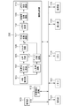
図1に本実施形態に係る撮像装置の構成を示す。
(First embodiment)
FIG. 1 shows a configuration of an imaging apparatus according to the present embodiment.
撮像部100は光学系に入射される光束を受光し、A/D(アナログ/デジタル)変換によってデジタル化された画像信号を出力する。撮像部100は光学系を構成するものとしてフォーカスレンズを含むレンズ群、シャッター、絞り、そして撮像センサを有し、シャッター、絞りおよびフォーカスレンズは撮像制御回路113によってそれぞれ制御することが可能である。撮像センサとしては、本実施形態ではX−Yアドレス型、RGB画素のBayer配列のCMOSセンサであるものとするが、これに限らない。例えばCCD(Charge Coupled Device)であってもよいし、補色の画素を配列したセンサなどであってもよい。
The
発光部101は、撮像部100による撮影の際に補助光として被写体を照射可能なストロボである。本実施形態では、黒体放射軸から比較的離れた色度にあるLEDストロボとする。
The
撮像部100から出力された画像データは画像処理部200へ入力すると同時に、メモリ102に記憶することができる。メモリ102に記憶した画像データは再度読み出すことができ、CPU(Central Processing Unit)114が画像データを参照したり、読み出した画像データを画像処理部200に入力することが可能である。本実施形態では、CPU114が、撮像部100によって発光部101が発光している状態で撮影された発光画像と発光部101が発光していない状態で撮影された非発光画像の明るさを測定することで測光を行う測光手段を担う。この測光結果に基づいて、後段の画像処理部200内でホワイトバランス補正処理が行われる。
The image data output from the
画像処理部200で画像処理された画像データは、メモリ102に書き戻したり、CPU114から任意のデータを書き込んだりすることも可能である。
Image data subjected to image processing by the
表示部116は画像処理部200で画像処理されメモリ102に記憶されたデジタル画像データをD/A変換して、液晶ディスプレイのような表示媒体に画像を表示することができる。また、画像データだけでなく任意の情報を単独、もしくは画像と共に表示することが可能であり、撮影時の露出情報を表示したり、検出された顔領域に枠を表示したりすることも可能である。
The
記録部115は撮影した画像データをROM、SDカード等の記録媒体に記憶することができる。
The
画像処理部200内の処理について、本実施形態に関連する箇所を説明する。103はWB(ホワイトバランス)制御部であり、メモリ102に記憶された画像信号からの情報に基づいてホワイトバランス補正値(WB補正値)を算出し、メモリ102に記憶された画像信号に対してWB補正を行う。なお、このWB制御部103の詳細構成およびWB補正値の算出方法については後述する。
With respect to the processing in the
104は、WB制御部103によりWB補正された画像信号が最適な色で再現されるように色ゲインをかけて色差信号R−Y、B−Yに変換する色変換MTX(色変換マトリックス)回路である。105は色差信号R−Y、B−Yの帯域を制限するLPF(ローパスフィルタ)回路、106はLPF回路105で帯域制限された画像信号の内、飽和部分の偽色信号を抑圧するCSUP(Chroma Supress)回路である。一方、WB制御部103によりWB補正された画像信号はY(輝度信号)生成回路111にも出力されて輝度信号Yが生成され、生成された輝度信号Yに対してエッジ強調回路112にてエッジ強調処理が施される。
CSUP回路106から出力される色差信号R−Y、B−Yと、エッジ強調回路112から出力される輝度信号Yは、RGB変換回路107にてRGB信号に変換され、ガンマ補正回路108にて階調補正が施される。その後、色輝度変換回路109にてYUV信号に変換され、さらにJPEG圧縮回路110にて圧縮されてメモリ102に書き込まれ、外部記録媒体または内部記録媒体に画像信号として記録される。あるいは表示部116にて表示媒体に表示される。あるいは不図示の外部出力に出力されるなどしても良い。
The color difference signals RY and BY output from the
ここで、上述した各構成はその一部あるいは全てをソフトウェアモジュールとして構成していても良いものとする。 Here, a part or all of each of the above-described configurations may be configured as a software module.
次に、図1のWB制御部103におけるWB補正値の算出方法について詳細に説明する。図2はWB補正値算出処理のフローチャートである。この処理は主にCPU114およびWB制御部103によって行われる。
Next, a method for calculating the WB correction value in the
まず、メモリ102に記憶された画像信号を読み出し、その画面を任意のm個のブロックに分割する(ステップS101)。そして、各ブロック(1〜m)毎に、画素値を各色ごとに加算平均して色平均値(R[i]、G[i]、B[i])を算出し、以下の式(1)を用いて色評価値(Cx[i]、Cy[i])を算出する(ステップS102)ことで画像データの色味を評価する。
Cx[i]=(R[i]−B[i])/Y[i]×1024
Cy[i]=(R[i]+B[i]−2G[i])/Y[i]×1024 ・・・(1)
ただし、Y[i]=R[i]+2G[i]+B[i]
First, the image signal stored in the
Cx [i] = (R [i] −B [i]) / Y [i] × 1024
Cy [i] = (R [i] + B [i] -2G [i]) / Y [i] × 1024 (1)
However, Y [i] = R [i] + 2G [i] + B [i]
次に、ステップS102で算出したi番目のブロックの色評価値(Cx[i]、Cy[i])が、図3に示す予め設定した白検出範囲301に含まれるかどうかを判断する(ステップS103)。
Next, it is determined whether or not the color evaluation value (Cx [i], Cy [i]) of the i-th block calculated in step S102 is included in the preset
白検出範囲301は、予め異なる光源下で白を撮影し、算出した色評価値を色度図上にプロットしたものであり、すなわち各光源下で白候補となる画素が存在する領域に対応する。この白検出範囲は撮影モードによって別設定できるものとする。図3におけるx座標(Cx)の負方向が高色温度被写体の白を撮影したときの色評価値、正方向が低色温度被写体の白を撮影したときの色評価値である。またy座標(Cy)は光源の緑成分の度合いを意味しており、負方向になるにつれGreen(緑)成分が大きくなり、つまり蛍光灯であることを示している。図3(a)に示すように、キセノン管のストロボの場合、黒体放射に近い高色温度の部分に色度が位置していた。しかし、LEDストロボの光源は、色度がLEDの種類によってさまざまであり、図3のaに示したように強く緑味が強い場所に位置するものも少なくない。
The
そのようなLEDストロボであって、外光を含まない環境下においては、LEDストロボのみにおける白色分布はGreen方向に偏って分布するので、白検出範囲はGreen方向を検出するような範囲に設定することになる(図3(b)の302)。外光をほとんど含まずLEDストロボのみで被写体が撮影されたと判断された場合においては、このように白検出エリアを移動させてホワイトバランス制御を行ってもよい。 In such an LED strobe, in an environment that does not include external light, the white distribution only in the LED strobe is distributed in the Green direction, so the white detection range is set to a range that detects the Green direction. (302 in FIG. 3B). In the case where it is determined that the subject is photographed with only the LED strobe with little external light, the white balance control may be performed by moving the white detection area in this way.
算出した色評価値(Cx[i]、Cy[i])がこの白検出範囲302に含まれる場合には(ステップS103でYES)そのブロックが白色であると判断する。そして、そのブロックの色平均値(R[i]、G[i]、B[i])を積算していく(ステップS104)。算出した色評価値(Cx[i]、Cy[i])がこの白検出範囲302に含まれない場合には加算せずにステップS105に進む。このステップS103及びステップS104の処理は、式(2)により表すことができる。 When the calculated color evaluation values (Cx [i], Cy [i]) are included in the white detection range 302 (YES in step S103), it is determined that the block is white. Then, the color average values (R [i], G [i], B [i]) of the block are integrated (step S104). If the calculated color evaluation values (Cx [i], Cy [i]) are not included in the white detection range 302, the process proceeds to step S105 without adding them. The processing of step S103 and step S104 can be expressed by equation (2).

ここで、式(2)において、色評価値(Cx[i]、Cy[i])が白検出範囲(図3(b)の302)に含まれる場合はSw[i]を1に、含まれない場合にはSw[i]を0とする。これにより、ステップS103の判断により色評価値(R[i]、G[i]、B[i])の加算を行うか、行わないかの処理を実質的に行っている。 Here, in the expression (2), if the color evaluation value (Cx [i], Cy [i]) is included in the white detection range (302 in FIG. 3B), Sw [i] is included in 1. If not, Sw [i] is set to 0. Thereby, the process of whether or not to add the color evaluation values (R [i], G [i], B [i]) is substantially performed according to the determination in step S103.
ステップS105では、すべてのブロックについて上記処理を行ったかどうかを判断し、未処理のブロックがあればステップS102に戻って上記処理を繰り返し、すべてのブロックの処理が終了していればステップS106に進む。 In step S105, it is determined whether or not the above process has been performed for all blocks. If there is an unprocessed block, the process returns to step S102 to repeat the above process, and if all the blocks have been processed, the process proceeds to step S106. .
ステップ106では、得られた色評価値の積分値(sumR、sumG、sumB)から、以下の式(3)を用いて、第1のWB補正値(WBCo1_R、WBCo1_G、WBCo1_B)を算出する。
WBCo1_R=sumY×1024/sumR
WBCo1_G=sumY×1024/sumG ・・・(3)
WBCo1_B=sumY×1024/sumB
ただし、sumY=(sumR+2×sumG+sumB)/4
In
WBCo1_R = sumY × 1024 / sumR
WBCo1_G = sumY × 1024 / sumG (3)
WBCo1_B = sumY × 1024 / sumB
However, sumY = (sumR + 2 × sumG + sumB) / 4
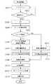
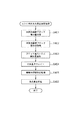
図4は本実施例における静止画撮影するフローを示したフローチャートである。 FIG. 4 is a flowchart showing a flow of still image shooting in this embodiment.
ステップS201では表示部116が、撮像部100から周期的に出力される画像をライブ画像として表示するライブビューモードであり、ライブ画像が表示されている。ステップS202で撮影指示がなされるとステップS203で静止画撮影用の露出計算を行う。(AutoExposure,AE)。ステップS204では、ステップS203でAEを行った結果、被写体が暗い場合にストロボの発光判定がなされる。ステップS205でストロボ発光がされると判定された場合、ステップS206ではストロボ非発光画像を取得する。
In step S201, the
ステップS207では本露光静止画撮影がなされ、ステップS208にてストロボ用白検出枠の設定がなされる。ステップS208での処理の詳細は後述する。一方ステップS205にてストロボ発光されない場合には、ステップS210にて本露光静止画撮影がなされ、S211にて通常の外光用の白検出枠が設定させる。ステップS209では実際の検出回路に白検出枠が設定がなされ、ステップS212にて白検出動作が行われる。ステップS213にて前述したホワイトバランス係数算出処理がなされ、ステップS214にて現像処理がなされる。 In step S207, actual exposure still image shooting is performed. In step S208, a strobe white detection frame is set. Details of the processing in step S208 will be described later. On the other hand, if the flash is not emitted in step S205, the main exposure still image is taken in step S210, and a normal white detection frame for external light is set in step S211. In step S209, a white detection frame is set in the actual detection circuit, and a white detection operation is performed in step S212. The white balance coefficient calculation process described above is performed in step S213, and the development process is performed in step S214.
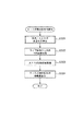
図5は図4のステップS208のストロボ白検出枠設定方法を説明したフローチャートである。 FIG. 5 is a flowchart for explaining the strobe white detection frame setting method in step S208 of FIG.
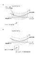
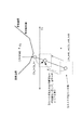
図5において、ステップS301では外光とストロボの光量比率の算出を行う。詳細は後述する。ステップS302ではライブ画像表示時のストロボ非発光状態でのWB係数に対応するCxCy値を取得する。ステップS303ではあらかじめ測定してあるLEDストロボのWB係数に対応するCxCy値を取得する。S304ではストロボ用の白検出枠の移動量を算出する。図7はステップS304でのストロボ用の白検出枠の移動する様子を示した概念図である。 In FIG. 5, in step S301, the light quantity ratio between the external light and the strobe is calculated. Details will be described later. In step S302, the CxCy value corresponding to the WB coefficient in the strobe non-light emission state at the time of live image display is acquired. In step S303, a CxCy value corresponding to the WB coefficient of the LED strobe measured in advance is acquired. In S304, the movement amount of the white detection frame for the strobe is calculated. FIG. 7 is a conceptual diagram showing how the strobe white detection frame moves in step S304.
その移動方法は、ステップS301で算出されたストロボと外光の光量比率に基づいて行われ、それにより適切なホワイトバランスの検出が可能となる。
本実施例ではその1例としてストロボ光量比率に応じて線形的に変化させる例を記載する。
図7は本実施例における、ストロボと外光の光量比率に応じて白検出範囲を可変させる様子を示した概念図である。
The moving method is performed based on the strobe / external light quantity ratio calculated in step S301, thereby making it possible to detect an appropriate white balance.
In the present embodiment, as an example, an example is described in which it is linearly changed according to the strobe light amount ratio.
FIG. 7 is a conceptual diagram showing how the white detection range is varied in accordance with the light quantity ratio between the strobe and the outside light in this embodiment.
LEDストロボ用のWB係数および制御値(第1のホワイトバランス制御値)をCx_swb_led、Cy_swb_ledとし、ストロボ用の白検出範囲幅をSerchAreaCx、SerchAreaCyとする。このとき、ストロボ用白サーチエリア(白検出領域)、Cx_ledserchArea、Cy_ledserchAreaは下記の式(4)のように記載できる。
Cx_ledserchArea=[Cx_swb_led−SerchAreaCx:Cx_swb_led+SerchAreaCx]
Cy_ledserchArea=[Cy_swb_led−SerchAreaCy:Cy_swb_led+SerchAreaCy]
(4)
The WB coefficient and control value (first white balance control value) for the LED strobe are Cx_swb_led and Cy_swb_led, and the white detection range width for the strobe is SearchAreaCx and SearchAreaCy. At this time, the strobe white search area (white detection area), Cx_ledsearchArea, and Cy_ledsearchArea can be described as the following equation (4).
Cx_ledsearchArea = [Cx_swb_led-SearchAreaCx: Cx_swb_led + SearchAreaCx]
Cy_ledsearchArea = [Cy_swb_led-SearchAreaCy: Cy_swb_led + SearchAreaCy]
(4)
また、外光としてライブビュー時のWB制御係数を(第2のホワイトバランス制御値)Cx_lv、Cy_lv、白検出枠の移動量をOffset_Cx、Offset_Cy、ストロボ・外光の光量比率をFlash_Ratioとすると、下記の式(5)のように記載できる。
offsetCx=(Cx_lv−Cx_swb_led)*(1−Flash_Ratio)
offsetCy=(Cy_lv−Cy_swb_led)*(1−Flash_Ratio)
(5)
Assuming that the WB control coefficient during live view is (second white balance control value) Cx_lv, Cy_lv, the amount of movement of the white detection frame is Offset_Cx, Offset_Cy, and the strobe / outside light amount ratio is Flash_Ratio as external light. (5).
offsetCx = (Cx_lv-Cx_swb_led) * (1-Flash_Ratio)
offsetCy = (Cy_lv-Cy_swb_led) * (1-Flash_Ratio)
(5)
その場合、ストロボ用の白検出範囲(白検出領域)は下記の式(6)のように記載できる。
Cx_ledserchArea=[Cx_swb_led−SerchAreaCx+offsetCx:Cx_swb_led+SerchAreaCx+offsetCx]
Cy_ledserchArea=[Cy_swb_led−SerchAreaCy+offsetCy:Cy_swb_led+SerchAreaCy+offsetCy]
(6)
In this case, the white detection range (white detection region) for the strobe can be described as the following formula (6).
Cx_ledsearchArea = [Cx_swb_led-SearchAreaCx + offsetCx: Cx_swb_led + SearchAreaCx + offsetCx]
Cy_ledsearchArea = [Cy_swb_led-SearchAreaCy + offsetCy: Cy_swb_led + SearchAreaCy + offsetCy]
(6)
このようにすることで、ストロボ光と外光の光量比率に応じてストロボの白検出枠を動的に可変させることができ、適切なホワイトバランス制御が可能となる。 By doing so, the white detection frame of the strobe can be dynamically varied according to the light quantity ratio between the strobe light and the outside light, and appropriate white balance control can be performed.
一般的に光および色は光の加法性を有するので、ホワイトバランス係数や白検出範囲を外光とストロボ光の光量比に応じて線形補間することは、有効な白検出範囲の移動方法といえる。 In general, light and color have light additivity. Therefore, linear interpolation of the white balance coefficient and white detection range according to the light quantity ratio between outside light and strobe light is an effective method for moving the white detection range. .
本実施例では、光量比率に対して線形的に移動量を制御したが、閾値を持ち所定閾値以上のストロボ光量比率の場合にはストロボ用の白検出範囲に設定し、閾値以下の場合には外光用の白検出範囲に設定してもよい。ストロボ光量比率に応じて白検出範囲の移動量をルックアップテーブル形式などの非線形性を持たせてもよいことは言うまでもない。 In this embodiment, the movement amount is controlled linearly with respect to the light amount ratio. However, when the strobe light amount ratio has a threshold value and is equal to or greater than the predetermined threshold value, the white detection range for the strobe is set. You may set to the white detection range for external light. It goes without saying that the amount of movement of the white detection range may have nonlinearity such as a look-up table format in accordance with the strobe light amount ratio.
もちろんストロボ発光量の制御情報を用いて、一定以上に発光量が小さい時に外光の白検出範囲としてもよい。また、それに追加して自動焦点制御装置(AutoFoucus、AF)の結果からえられる被写体距離とストロボの発光量からストロボ照射量およびストロボ外光比率を推定してもよいことは言うまでもない。 Of course, the control information of the strobe light emission amount may be used as a white detection range of outside light when the light emission amount is smaller than a certain level. In addition, it goes without saying that the strobe irradiation amount and the strobe external light ratio may be estimated from the subject distance obtained from the result of the automatic focus control device (AutoFocus, AF) and the light emission amount of the strobe.
図6は、図5のS301の外光・ストロボ光量比率算出処理を詳細に説明したフローチャートである。図6において、S401ではS206で取得された非発光画像より複数のブロックに領域分割したときのブロック積分値の取得を行う。ステップS402はS207で取得された本露光画像から複数のブロックに領域分割したときのブロック積分値の取得を行う。 FIG. 6 is a flowchart illustrating in detail the external light / strobe light amount ratio calculation process of S301 in FIG. In FIG. 6, in S401, the block integration value when the area is divided into a plurality of blocks from the non-light emitting image acquired in S206 is acquired. In step S402, a block integration value is obtained when the region is divided into a plurality of blocks from the main exposure image acquired in S207.
ステップS403では本露光画像におけるブロック毎のストロボ照射量(FlashY[i])と外光照射量(PreY[i])の算出を行う。
非発光画像の感度(Sv_pre)・F値(Av_ pre)、露出時間(Tv_ pre)とブロック積分値(Pre _Y),本露光画像の感度(Sv_cap)・F値(Av_cap)、露出時間(Tv_cap)とブロック積分値CapY(x,y)の関係から、式(7)によって非発光画像の輝度値を本露光撮影条件に換算処理を行った輝度値(PreY´[i])の算出を行う。ただしSv_preなどの値は下記のApexで表現されたものである。
In step S403, the strobe irradiation amount (FlashY [i]) and the external light irradiation amount (PreY [i]) for each block in the main exposure image are calculated.
Non-luminous image sensitivity (Sv_pre) / F value (Av_pre), exposure time (Tv_pre) and block integration value (Pre_Y), main exposure image sensitivity (Sv_cap) / F value (Av_cap), exposure time (Tv_cap) ) And the block integral value CapY (x, y), the luminance value (PreY ′ [i]) obtained by converting the luminance value of the non-luminous image into the main exposure photographing condition is calculated by the equation (7). . However, values such as Sv_pre are expressed by the following Apex.
ここで、PreY´[i]がブロック毎の本露光時の外光光量に相当し、FlashY[i]はブロック毎の本露光時のストロボ照射量に相当している。S404では、ブロック毎に算出されたFlashYに中央重点の重みテーブル(CenterWwight[i])の乗算を行う(FlashY_wgt[i])。 Here, PreY ′ [i] corresponds to the amount of external light at the time of main exposure for each block, and FlashY [i] corresponds to the amount of strobe irradiation at the time of main exposure for each block. In S404, FlashY calculated for each block is multiplied by the weighting table (CenterWight [i]) of the center weight (FlashY_wgt [i]).
同様に非発光画像の発光量も同様にして中央重点の重みの乗算を行う(あわせて式(8))。 Similarly, the light emission amount of the non-light-emitting image is similarly multiplied by the weight of the center weight (also, equation (8)).
これで発光画像、非発光画像それぞれにおいて、明るさが算出された。 Thus, the brightness was calculated for each of the light emitting image and the non-light emitting image.
ステップS405では被写体領域特定処理を行う。より具体的には、FlashY_wgt[i]値から、輝度の高い順にソートして上位50%の領域を有効領域として値を残し、下位50%のブロック値を無効領域として、FlashY_wgt[i]値を0にする。さらにメディアンフィルタを適用し、ノイズや微小なストロボ反射領域といったごみ領域の判定を行う。ごみ領域と判定された部分は同様にしてFlashY_wgt[i]値を0にする。こうして算出されたブロックデータは、中央領域かつストロボの照射が強い、一定以上の面積を持つ領域の抽出ができ、この領域を主被写体領域と判定できる。(Main_TgtTbl[i]) In step S405, subject area specifying processing is performed. More specifically, from the FlashY_wgt [i] value, the values are sorted in descending order of brightness, leaving the upper 50% area as the effective area, leaving the lower 50% block value as the invalid area, and the FlashY_wgt [i] value as the invalid area. Set to zero. In addition, a median filter is applied to determine dust areas such as noise and minute strobe reflection areas. Similarly, the FlashY_wgt [i] value is set to 0 for the part determined to be a garbage area. The block data calculated in this way can extract a central region and a region having a certain area or more with strong strobe irradiation, and this region can be determined as a main subject region. (Main_TgtTbl [i])
ステップS406では、ステップS405で算出された主被写体領域に対して、FlashY[i]値の積分値(FlashLightVal)とPreY‘[i]の積分値(DayLightVal)を算出する。そして、下記の式(9)にて外光とストロボの光量比(Flash_Ratio)を算出できる。 In step S406, an integrated value (FlashLightVal) of the FlashY [i] value and an integrated value (DayLightVal) of PreY ′ [i] are calculated for the main subject area calculated in step S405. Then, the light quantity ratio (Flash_Ratio) between the external light and the strobe can be calculated by the following formula (9).
本実施例ではメイン被写体領域を、なるべく中央に近くてかつストロボの照射された領域と判断した。しかし、もちろんこれだけではなく、顔判別する手法や、色や明るさなどの情報から画像領域を分割して、さらにその中からメイン被写体領域を特定するなどの方法でもよい。また、画像のパターンマッチング方法などを応用した被写体認識などの手法を用いて、被写体領域を特定してもよい。これらの方法においても被写体領域の特定ができれば、前述したMain_TgtTbl[i]の算出方法が変わるだけであり、そのメイン領域におけるストロボと外光の光量比の算出は同様にして可能である。 In this embodiment, the main subject area is determined to be as close to the center as possible and the area irradiated with the strobe. However, of course, not only this, but also a method for identifying a face, a method of dividing an image region from information such as color and brightness, and further specifying a main subject region from the image region. Alternatively, the subject region may be specified using a method such as subject recognition that applies an image pattern matching method or the like. In these methods, if the subject region can be specified, only the calculation method of Main_TgtTbl [i] described above is changed, and the light amount ratio between the strobe and the external light in the main region can be calculated in the same manner.
以上のように、本実施形態では、演色性の劣るストロボ光と蛍光灯などの外光との光量比率を算出し、この光量比率に基づいて白検出枠を移動させる。これにより、通常光源に加えて演色性の悪い光源下においてもホワイトバランスを適切に調整できる。 As described above, in this embodiment, the light quantity ratio between strobe light with poor color rendering properties and external light such as a fluorescent lamp is calculated, and the white detection frame is moved based on this light quantity ratio. This makes it possible to appropriately adjust the white balance even under a light source with poor color rendering properties in addition to the normal light source.
(他の実施形態)
本発明の目的は以下のようにしても達成できる。すなわち、前述した各実施形態の機能を実現するための手順が記述されたソフトウェアのプログラムコードを記録した記憶媒体を、システムまたは装置に供給する。そしてそのシステムまたは装置のコンピュータ(またはCPU、MPU等)が記憶媒体に格納されたプログラムコードを読み出して実行するのである。
(Other embodiments)
The object of the present invention can also be achieved as follows. That is, a storage medium in which a program code of software in which a procedure for realizing the functions of the above-described embodiments is described is recorded is supplied to the system or apparatus. The computer (or CPU, MPU, etc.) of the system or apparatus reads out and executes the program code stored in the storage medium.
この場合、記憶媒体から読み出されたプログラムコード自体が本発明の新規な機能を実現することになり、そのプログラムコードを記憶した記憶媒体およびプログラムは本発明を構成することになる。 In this case, the program code itself read from the storage medium realizes the novel function of the present invention, and the storage medium and program storing the program code constitute the present invention.
また、プログラムコードを供給するための記憶媒体としては、例えば、フレキシブルディスク、ハードディスク、光ディスク、光磁気ディスクなどが挙げられる。また、CD−ROM、CD−R、CD−RW、DVD−ROM、DVD−RAM、DVD−RW、DVD−R、磁気テープ、不揮発性のメモリカード、ROM等も用いることができる。 Examples of the storage medium for supplying the program code include a flexible disk, a hard disk, an optical disk, and a magneto-optical disk. Further, a CD-ROM, CD-R, CD-RW, DVD-ROM, DVD-RAM, DVD-RW, DVD-R, magnetic tape, nonvolatile memory card, ROM, or the like can also be used.
また、コンピュータが読み出したプログラムコードを実行可能とすることにより、前述した各実施形態の機能が実現される。さらに、そのプログラムコードの指示に基づき、コンピュータ上で稼動しているOS(オペレーティングシステム)等が実際の処理の一部または全部を行い、その処理によって前述した各実施形態の機能が実現される場合も含まれる。 Further, by making the program code read by the computer executable, the functions of the above-described embodiments are realized. Furthermore, when the OS (operating system) running on the computer performs part or all of the actual processing based on the instruction of the program code, the functions of the above-described embodiments are realized by the processing. Is also included.
更に、以下の場合も含まれる。まず記憶媒体から読み出されたプログラムコードが、コンピュータに挿入された機能拡張ボードやコンピュータに接続された機能拡張ユニットに備わるメモリに書き込まれる。その後、そのプログラムコードの指示に基づき、その機能拡張ボードや機能拡張ユニットに備わるCPU等が実際の処理の一部または全部を行う。 Furthermore, the following cases are also included. First, the program code read from the storage medium is written in a memory provided in a function expansion board inserted into the computer or a function expansion unit connected to the computer. Thereafter, based on the instruction of the program code, the CPU or the like provided in the function expansion board or function expansion unit performs part or all of the actual processing.
また、本発明はデジタルカメラのような撮影を主目的とした機器にかぎらず、携帯電話、パーソナルコンピュータ(ラップトップ型、デスクトップ型、タブレット型など)、ゲーム機など、撮像装置を内蔵もしくは外部接続する任意の機器に適用可能である。従って、本明細書における「撮像装置」は、撮像機能を備えた任意の電子機器を包含することが意図されている。 In addition, the present invention is not limited to devices such as digital cameras, but includes built-in or external connection of imaging devices such as mobile phones, personal computers (laptop type, desktop type, tablet type, etc.), game machines, etc. It can be applied to any device. Therefore, the “imaging device” in this specification is intended to include any electronic device having an imaging function.
Claims (8)
前記撮像手段が被写体を撮像する際に、当該被写体を照射可能な発光手段による発光を測光する測光手段と、
撮像手段で取得した画像データの色味を評価する色評価手段と、
前記色評価手段による色評価結果から、前記発光手段に対応する白候補画素を抽出する白検出領域を、前記測光手段による測光結果に基づいて可変させて白検出を行う白検出手段と、
前記白検出領域による白検出の結果に応じて、ホワイトバランス補正を行うホワイトバランス補正手段と、
を有することを特徴とする撮像装置。 Imaging means;
A photometric means for measuring light emitted by a light emitting means capable of irradiating the subject when the imaging means images the subject;
Color evaluation means for evaluating the color of the image data acquired by the imaging means;
A white detection unit for performing white detection by varying a white detection region for extracting a white candidate pixel corresponding to the light emitting unit based on a photometric result by the photometric unit, from a color evaluation result by the color evaluating unit;
White balance correction means for performing white balance correction according to the result of white detection by the white detection area;
An imaging device comprising:
前記白検出手段は、当該発光画像及び非発光画像の明るさの比率から前記白検出領域を設定することを特徴とする請求項1に記載の撮像装置。 The light metering means calculates the brightness of each of a light emitting image that is shot while the light emitting means is emitting light and a non-light emitting image that is shot when the light emitting means is not emitting light,
The imaging apparatus according to claim 1, wherein the white detection unit sets the white detection region based on a brightness ratio between the light-emitting image and the non-light-emitting image.
撮像手段で取得した画像データの色味を評価する色評価ステップと、
前記色評価ステップによる色評価結果から、前記発光手段に対応する白候補画素を抽出する白検出領域を、前記測光手段による測光結果に基づいて可変させて白検出を行う白検出ステップと、
前記白検出領域による白検出の結果に応じて、ホワイトバランス補正を行うホワイトバランス補正ステップと、
を有することを特徴とする撮像装置の制御方法。 A method for controlling an imaging apparatus, comprising: an imaging unit; and a photometric unit that measures light emitted by a light emitting unit capable of irradiating the subject when the imaging unit images the subject,
A color evaluation step for evaluating the color of the image data acquired by the imaging means;
A white detection step for performing white detection by varying a white detection region for extracting a white candidate pixel corresponding to the light emitting means from a color evaluation result by the color evaluation step based on a photometry result by the photometry means;
A white balance correction step for performing white balance correction according to a result of white detection by the white detection region;
A method for controlling an imaging apparatus, comprising:
Priority Applications (1)
| Application Number | Priority Date | Filing Date | Title |
|---|---|---|---|
| JP2012279824A JP6053501B2 (en) | 2012-12-21 | 2012-12-21 | IMAGING DEVICE AND IMAGING DEVICE CONTROL METHOD |
Applications Claiming Priority (1)
| Application Number | Priority Date | Filing Date | Title |
|---|---|---|---|
| JP2012279824A JP6053501B2 (en) | 2012-12-21 | 2012-12-21 | IMAGING DEVICE AND IMAGING DEVICE CONTROL METHOD |
Publications (2)
| Publication Number | Publication Date |
|---|---|
| JP2014123902A true JP2014123902A (en) | 2014-07-03 |
| JP6053501B2 JP6053501B2 (en) | 2016-12-27 |
Family
ID=51404062
Family Applications (1)
| Application Number | Title | Priority Date | Filing Date |
|---|---|---|---|
| JP2012279824A Active JP6053501B2 (en) | 2012-12-21 | 2012-12-21 | IMAGING DEVICE AND IMAGING DEVICE CONTROL METHOD |
Country Status (1)
| Country | Link |
|---|---|
| JP (1) | JP6053501B2 (en) |
Cited By (1)
| Publication number | Priority date | Publication date | Assignee | Title |
|---|---|---|---|---|
| JP2016019081A (en) * | 2014-07-07 | 2016-02-01 | キヤノン株式会社 | Image processing system, control method thereof, and control program |
Citations (4)
| Publication number | Priority date | Publication date | Assignee | Title |
|---|---|---|---|---|
| JPH09214984A (en) * | 1996-02-01 | 1997-08-15 | Canon Inc | Imaging device and means provided in the imaging device |
| JPH11262029A (en) * | 1997-12-25 | 1999-09-24 | Canon Inc | Imaging device and signal processing device |
| JP2005080011A (en) * | 2003-09-01 | 2005-03-24 | Canon Inc | Imaging method, imaging apparatus, program, and storage medium |
| JP2007173933A (en) * | 2005-12-19 | 2007-07-05 | Eastman Kodak Co | Digital camera, gain calculation apparatus, and gain calculation method |
-
2012
- 2012-12-21 JP JP2012279824A patent/JP6053501B2/en active Active
Patent Citations (4)
| Publication number | Priority date | Publication date | Assignee | Title |
|---|---|---|---|---|
| JPH09214984A (en) * | 1996-02-01 | 1997-08-15 | Canon Inc | Imaging device and means provided in the imaging device |
| JPH11262029A (en) * | 1997-12-25 | 1999-09-24 | Canon Inc | Imaging device and signal processing device |
| JP2005080011A (en) * | 2003-09-01 | 2005-03-24 | Canon Inc | Imaging method, imaging apparatus, program, and storage medium |
| JP2007173933A (en) * | 2005-12-19 | 2007-07-05 | Eastman Kodak Co | Digital camera, gain calculation apparatus, and gain calculation method |
Cited By (1)
| Publication number | Priority date | Publication date | Assignee | Title |
|---|---|---|---|---|
| JP2016019081A (en) * | 2014-07-07 | 2016-02-01 | キヤノン株式会社 | Image processing system, control method thereof, and control program |
Also Published As
| Publication number | Publication date |
|---|---|
| JP6053501B2 (en) | 2016-12-27 |
Similar Documents
| Publication | Publication Date | Title |
|---|---|---|
| US10397486B2 (en) | Image capture apparatus and method executed by image capture apparatus | |
| JP5761946B2 (en) | Image processing apparatus, image processing method, and storage medium | |
| JP6049343B2 (en) | Image processing apparatus, image processing method, and program | |
| JP5665436B2 (en) | Image processing apparatus, image processing method, and program | |
| JP5743696B2 (en) | Image processing apparatus, image processing method, and program | |
| JP5808142B2 (en) | Image processing apparatus, image processing method, and program | |
| JP5728498B2 (en) | Imaging apparatus and light emission amount control method thereof | |
| JP5804857B2 (en) | Image processing apparatus, image processing method, and program | |
| JP5804856B2 (en) | Image processing apparatus, image processing method, and program | |
| JP5225137B2 (en) | Imaging apparatus, image processing method, and program | |
| JP2018107741A (en) | Image processing apparatus, image processing method, and program | |
| JP2013143593A (en) | Imaging device, control method thereof, and program | |
| JP5854716B2 (en) | Image processing apparatus, image processing method, and program | |
| JP6053501B2 (en) | IMAGING DEVICE AND IMAGING DEVICE CONTROL METHOD | |
| JP2018092350A (en) | Image processing apparatus, image processing method, and program | |
| US10021314B2 (en) | Image processing apparatus, image capturing apparatus, method of controlling the same, and storage medium for changing shading using a virtual light source | |
| JP2009063674A (en) | Imaging apparatus and flash control method | |
| JP6570311B2 (en) | Image processing apparatus and image processing method | |
| JP2016005105A (en) | Imaging apparatus | |
| JP2013132065A (en) | Imaging apparatus and flash control method | |
| JP6616674B2 (en) | Image processing apparatus and method, and imaging apparatus | |
| JP2021087125A (en) | Image processing device, control method thereof, and program | |
| JP2014127964A (en) | Image processing device, image processing method, and program | |
| JP5943682B2 (en) | Imaging apparatus, control method thereof, and program | |
| JP6021885B2 (en) | Image processing apparatus, image processing method, and program |
Legal Events
| Date | Code | Title | Description |
|---|---|---|---|
| A621 | Written request for application examination |
Free format text: JAPANESE INTERMEDIATE CODE: A621 Effective date: 20151221 |
|
| A977 | Report on retrieval |
Free format text: JAPANESE INTERMEDIATE CODE: A971007 Effective date: 20160707 |
|
| A131 | Notification of reasons for refusal |
Free format text: JAPANESE INTERMEDIATE CODE: A131 Effective date: 20160719 |
|
| A521 | Request for written amendment filed |
Free format text: JAPANESE INTERMEDIATE CODE: A523 Effective date: 20160905 |
|
| A131 | Notification of reasons for refusal |
Free format text: JAPANESE INTERMEDIATE CODE: A131 Effective date: 20160927 |
|
| A521 | Request for written amendment filed |
Free format text: JAPANESE INTERMEDIATE CODE: A523 Effective date: 20161007 |
|
| TRDD | Decision of grant or rejection written | ||
| A01 | Written decision to grant a patent or to grant a registration (utility model) |
Free format text: JAPANESE INTERMEDIATE CODE: A01 Effective date: 20161101 |
|
| A61 | First payment of annual fees (during grant procedure) |
Free format text: JAPANESE INTERMEDIATE CODE: A61 Effective date: 20161129 |
|
| R151 | Written notification of patent or utility model registration |
Ref document number: 6053501 Country of ref document: JP Free format text: JAPANESE INTERMEDIATE CODE: R151 |