JP2014129961A - Air conditioner - Google Patents

Air conditioner Download PDF

Info

Publication number
JP2014129961A
JP2014129961A JP2012288502A JP2012288502A JP2014129961A JP 2014129961 A JP2014129961 A JP 2014129961A JP 2012288502 A JP2012288502 A JP 2012288502A JP 2012288502 A JP2012288502 A JP 2012288502A JP 2014129961 A JP2014129961 A JP 2014129961A
Authority
JP
Japan
Prior art keywords
refrigerant
heat exchanger
receiver
compressor
indoor
Prior art date
Legal status (The legal status is an assumption and is not a legal conclusion. Google has not performed a legal analysis and makes no representation as to the accuracy of the status listed.)
Pending
Application number
JP2012288502A
Other languages
Japanese (ja)
Inventor
Keisuke Tanimoto
啓介 谷本
Komei Yumoto
孔明 湯本
Yukako Kanazawa
友佳子 金澤
Current Assignee (The listed assignees may be inaccurate. Google has not performed a legal analysis and makes no representation or warranty as to the accuracy of the list.)
Daikin Industries Ltd
Original Assignee
Daikin Industries Ltd
Priority date (The priority date is an assumption and is not a legal conclusion. Google has not performed a legal analysis and makes no representation as to the accuracy of the date listed.)
Filing date
Publication date
Application filed by Daikin Industries Ltd filed Critical Daikin Industries Ltd
Priority to JP2012288502A priority Critical patent/JP2014129961A/en
Publication of JP2014129961A publication Critical patent/JP2014129961A/en
Pending legal-status Critical Current

Links

Images

Landscapes

  • Other Air-Conditioning Systems (AREA)
  • Air Conditioning Control Device (AREA)

Abstract

【課題】四路切換弁によって冷房運転と暖房運転とを切り換えて行う空気調和装置において、伝熱管として扁平多穴管を使用する熱交換器を室外熱交換器として採用しても、暖房運転の再開時に、圧縮機が液冷媒を吸入しにくくして、圧縮機の信頼性が損なわれないようにする。
【解決手段】空気調和装置(1)では、室外熱交換器(23)と膨張弁(26)との間にレシーバ(25)を設けて、暖房運転を停止する際に、四路切換弁(22)を暖房サイクル状態から冷房サイクル状態に切り換えて、レシーバ(25)に冷媒を強制的に溜めるレシーバ液溜め制御を行い、その後に、圧縮機(21)を停止させる。
【選択図】図7
In an air conditioner that switches between a cooling operation and a heating operation by a four-way switching valve, even if a heat exchanger that uses a flat multi-hole tube as a heat transfer tube is adopted as an outdoor heat exchanger, When restarting, the compressor makes it difficult to suck the liquid refrigerant so that the reliability of the compressor is not impaired.
In an air conditioner (1), a receiver (25) is provided between an outdoor heat exchanger (23) and an expansion valve (26), and a four-way switching valve ( 22) is switched from the heating cycle state to the cooling cycle state, the receiver liquid reservoir control for forcibly storing the refrigerant in the receiver (25) is performed, and then the compressor (21) is stopped.
[Selection] Figure 7

Description

本発明は、空気調和装置、特に、四路切換弁によって冷房運転と暖房運転とを切り換えて行う空気調和装置に関する。   The present invention relates to an air conditioner, and more particularly to an air conditioner that switches between a cooling operation and a heating operation by a four-way switching valve.

従来より、特許文献1(特開2011−80649号公報)に示すように、四路切換弁によって冷房運転と暖房運転とを切り換えて行う空気調和装置がある。具体的には、空気調和装置は、圧縮機、四路切換弁、室外熱交換器、膨張弁、室内熱交換器が接続されることによって構成された冷媒回路を有している。そして、空気調和装置では、四路切換弁を冷房サイクル状態に切り換えることによって、圧縮機、室外熱交換器、膨張弁、室内熱交換器の順に冷媒を循環させる冷房運転が行われる。また、空気調和装置では、四路切換弁を暖房サイクル状態に切り換えることによって、圧縮機、室内熱交換器、膨張弁、室外熱交換器の順に冷媒を循環させる暖房運転が行われる。   Conventionally, as shown in Patent Document 1 (Japanese Patent Application Laid-Open No. 2011-80649), there is an air conditioner that performs switching between a cooling operation and a heating operation by a four-way switching valve. Specifically, the air conditioner has a refrigerant circuit configured by connecting a compressor, a four-way switching valve, an outdoor heat exchanger, an expansion valve, and an indoor heat exchanger. And in an air conditioning apparatus, the cooling operation which circulates a refrigerant | coolant in order of a compressor, an outdoor heat exchanger, an expansion valve, and an indoor heat exchanger is performed by switching a four-way switching valve to a cooling cycle state. Moreover, in an air conditioning apparatus, the heating operation which circulates a refrigerant | coolant in order of a compressor, an indoor heat exchanger, an expansion valve, and an outdoor heat exchanger is performed by switching a four-way switching valve to a heating cycle state.

上記従来の空気調和装置では、サーモオフやリモコンからの指令等によって、冷房運転を停止する際には、四路切換弁を冷房サイクル状態のままで、また、暖房運転を停止する際には、四路切換弁を暖房サイクル状態のままで、圧縮機を停止している。ここで、冷媒回路内の冷媒は、暖房運転時に冷凍サイクルの高圧であった部分(圧縮機の吐出側から膨張弁までの部分)から暖房運転時に冷凍サイクルの低圧であった部分(膨張弁から圧縮機の吸入側までの部分)に向かって流れる。すなわち、暖房運転を停止する際には、膨張弁側から室外熱交換器を通じて圧縮機の吸入側に向かって冷媒が流れることになる。   In the above conventional air conditioner, when the cooling operation is stopped by a thermo-off or a command from the remote controller, the four-way switching valve remains in the cooling cycle state, and when the heating operation is stopped, The compressor is stopped while the path switching valve remains in the heating cycle state. Here, the refrigerant in the refrigerant circuit is from the portion (the portion from the discharge side of the compressor to the expansion valve) of the refrigeration cycle during the heating operation to the portion (from the expansion valve) of the refrigeration cycle during the heating operation. It flows toward the suction side of the compressor. That is, when the heating operation is stopped, the refrigerant flows from the expansion valve side to the suction side of the compressor through the outdoor heat exchanger.

ここで、上記従来の空気調和装置において、伝熱管として扁平多穴管を使用する熱交換器を室外熱交換器として採用すると、上記のような暖房運転を停止する際の冷媒回路内の冷媒の流れによって、室外熱交換器の扁平多穴管内に溜まった液冷媒が圧縮機の吸入側に押し流されることになる。   Here, in the conventional air conditioner, when a heat exchanger that uses a flat multi-hole tube as a heat transfer tube is adopted as an outdoor heat exchanger, the refrigerant in the refrigerant circuit when the heating operation as described above is stopped. The flow causes the liquid refrigerant accumulated in the flat multi-hole tube of the outdoor heat exchanger to be pushed away to the suction side of the compressor.

このため、暖房運転を停止する際に、室外熱交換器から圧縮機の吸入側に大量の液冷媒が流入して溜まり込むおそれがある。そして、その後に、暖房運転を再開すると、圧縮機が液冷媒を吸入して、これにより、液圧縮が発生して圧縮機の信頼性が損なわれるおそれがある。   For this reason, when heating operation is stopped, a large amount of liquid refrigerant may flow from the outdoor heat exchanger to the suction side of the compressor and accumulate. Then, when the heating operation is resumed after that, the compressor sucks the liquid refrigerant, which may cause liquid compression and impair the reliability of the compressor.

これに対して、圧縮機の吸入側にアキュムレータ(圧縮機に付属する小容積のアキュムレータよりも大容積のもの)を設けて液冷媒を溜めることで、暖房運転の再開時に、圧縮機が液冷媒を吸入しにくくすることも考えられる。しかし、冷媒回路に封入される冷媒として、R32のような低温条件における冷凍機油の溶解度が非常に小さい冷媒を使用する場合には、圧縮機の吸入側にアキュムレータを設けることが好ましくない。すなわち、低温条件における冷凍機油の溶解度が小さい冷媒を使用する場合には、アキュムレータ内に溜まった冷媒と冷凍機油とが二層分離してしまい、圧縮機に冷凍機油が戻らなくなるおそれがあり、これにより、潤滑不足が発生して圧縮機の信頼性が損なわれるおそれがある。すなわち、低温条件における冷凍機油の溶解度が小さい冷媒を使用する場合のように圧縮機の吸入側にアキュムレータを設けることが好ましくない場合には、圧縮機の吸入側にアキュムレータを設けることができず、暖房運転の再開時に、圧縮機が液冷媒を吸入して、これにより、液圧縮が発生して圧縮機の信頼性が損なわれるおそれがある。   On the other hand, an accumulator (having a larger capacity than the small-capacity accumulator attached to the compressor) is provided on the suction side of the compressor to store the liquid refrigerant so that the compressor can be used when the heating operation is resumed. It may be possible to make inhalation difficult. However, when a refrigerant having a very low solubility of refrigerating machine oil under a low temperature condition such as R32 is used as the refrigerant enclosed in the refrigerant circuit, it is not preferable to provide an accumulator on the suction side of the compressor. That is, when using a refrigerant having low solubility of refrigerating machine oil under low temperature conditions, the refrigerant accumulated in the accumulator and the refrigerating machine oil may be separated into two layers, and the refrigerating machine oil may not return to the compressor. As a result, insufficient lubrication may occur and the reliability of the compressor may be impaired. That is, when it is not preferable to provide an accumulator on the suction side of the compressor as in the case of using a refrigerant having low solubility of refrigerating machine oil under low temperature conditions, an accumulator cannot be provided on the suction side of the compressor. When the heating operation is resumed, the compressor sucks the liquid refrigerant, which may cause liquid compression and impair the reliability of the compressor.

本発明の課題は、四路切換弁によって冷房運転と暖房運転とを切り換えて行う空気調和装置において、伝熱管として扁平多穴管を使用する熱交換器を室外熱交換器として採用しても、暖房運転の再開時に、圧縮機が液冷媒を吸入しにくくして、圧縮機の信頼性が損なわれないようにすることにある。   The subject of the present invention is an air conditioner that performs switching between cooling operation and heating operation by a four-way switching valve, even if a heat exchanger that uses a flat multi-hole tube as a heat transfer tube is adopted as an outdoor heat exchanger, This is to make it difficult for the compressor to suck the liquid refrigerant when resuming the heating operation so that the reliability of the compressor is not impaired.

第1の観点にかかる空気調和装置は、圧縮機、四路切換弁、室外熱交換器、膨張弁、室内熱交換器が接続されることによって構成された冷媒回路を有しており、四路切換弁を冷房サイクル状態に切り換えることによって、圧縮機、室外熱交換器、膨張弁、室内熱交換器の順に冷媒を循環させる冷房運転を行い、四路切換弁を暖房サイクル状態に切り換えることによって、圧縮機、室内熱交換器、膨張弁、室外熱交換器の順に冷媒を循環させる暖房運転を行う空気調和装置において、室外熱交換器は、伝熱管として扁平多穴管を使用する熱交換器であり、室外熱交換器と膨張弁との間にレシーバを設けて、暖房運転を停止する際に、四路切換弁を暖房サイクル状態から冷房サイクル状態に切り換えて、レシーバに冷媒を強制的に溜めるレシーバ液溜め制御を行い、その後に、圧縮機を停止させる。   An air conditioner according to a first aspect has a refrigerant circuit configured by connecting a compressor, a four-way switching valve, an outdoor heat exchanger, an expansion valve, and an indoor heat exchanger. By switching the switching valve to the cooling cycle state, performing a cooling operation in which the refrigerant is circulated in the order of the compressor, the outdoor heat exchanger, the expansion valve, and the indoor heat exchanger, and by switching the four-way switching valve to the heating cycle state, In an air conditioner that performs a heating operation in which refrigerant is circulated in the order of a compressor, an indoor heat exchanger, an expansion valve, and an outdoor heat exchanger, the outdoor heat exchanger is a heat exchanger that uses a flat multi-hole tube as a heat transfer tube. Yes, a receiver is provided between the outdoor heat exchanger and the expansion valve, and when the heating operation is stopped, the four-way switching valve is switched from the heating cycle state to the cooling cycle state to forcibly accumulate the refrigerant in the receiver. Receiver Performs a reservoir control, then, to stop the compressor.

四路切換弁によって冷房運転と暖房運転とを切り換えて行う空気調和装置では、暖房運転時に室外熱交換器が冷媒の蒸発器として機能する。このため、暖房運転を停止する際には、室外熱交換器の伝熱管として円管を使用しても、又は、扁平多穴管を使用しても、室外熱交換器の伝熱管内に液冷媒が溜まることになる。   In an air conditioner that switches between a cooling operation and a heating operation by a four-way switching valve, the outdoor heat exchanger functions as a refrigerant evaporator during the heating operation. For this reason, when stopping the heating operation, even if a circular tube is used as the heat transfer tube of the outdoor heat exchanger or a flat multi-hole tube is used, the liquid is put in the heat transfer tube of the outdoor heat exchanger. The refrigerant will accumulate.

しかし、伝熱管として円管を使用する室外熱交換器を採用する場合には、四路切換弁を暖房サイクル状態のままで圧縮機を停止しても、暖房運転の停止後の冷媒回路内の冷媒の流れによって、円管内に溜まった液冷媒は、圧縮機の吸入側にほとんど押し流されることはない。なぜなら、伝熱管として円管を使用する場合には、円管の下部空間に液冷媒が流れ、円管の上部空間にガス冷媒が流れるため、暖房運転の停止後に膨張弁側から室外熱交換器に冷媒が流入しても、主として、円管の上部空間に存在するガス冷媒が押し出されるからである。   However, when an outdoor heat exchanger that uses a circular pipe as the heat transfer pipe is adopted, even if the compressor is stopped with the four-way switching valve in the heating cycle state, the refrigerant circuit in the refrigerant circuit after the heating operation is stopped is used. Due to the flow of the refrigerant, the liquid refrigerant accumulated in the circular pipe is hardly pushed away to the suction side of the compressor. This is because when a circular pipe is used as the heat transfer pipe, liquid refrigerant flows in the lower space of the circular pipe and gas refrigerant flows in the upper space of the circular pipe. Therefore, the outdoor heat exchanger from the expansion valve side after the heating operation is stopped. This is because even if the refrigerant flows into the gas, the gas refrigerant present in the upper space of the circular pipe is mainly pushed out.

これに対して、伝熱管として扁平多穴管を使用する室外熱交換器を採用する場合には、扁平多穴管に形成された多数の小さな冷媒流路内が液冷媒によってほとんど満たされてしまい、ガス冷媒が流れる空間がほとんど形成されない。このため、伝熱管として扁平多穴管を使用する室外熱交換器を採用する場合には、四路切換弁を暖房サイクル状態のままで圧縮機を停止すると、暖房運転の停止後の膨張弁側から室外熱交換器への冷媒の流れによって、扁平多穴管内に溜まった液冷媒は、圧縮機の吸入側に押し流されてしまう。   On the other hand, when an outdoor heat exchanger using a flat multi-hole tube is adopted as the heat transfer tube, many small refrigerant flow paths formed in the flat multi-hole tube are almost filled with liquid refrigerant. The space through which the gas refrigerant flows is hardly formed. For this reason, when adopting an outdoor heat exchanger that uses a flat multi-hole tube as the heat transfer tube, if the compressor is stopped while the four-way switching valve remains in the heating cycle state, the expansion valve side after the heating operation is stopped Due to the flow of refrigerant from the outdoor heat exchanger to the outdoor heat exchanger, the liquid refrigerant accumulated in the flat multi-hole tube is pushed away to the suction side of the compressor.

そこで、ここでは、伝熱管の型式による暖房運転の停止後の冷媒挙動の相違を考慮して、室外熱交換器と膨張弁との間にレシーバを設けて、暖房運転を停止する際に、四路切換弁を暖房サイクル状態から冷房サイクル状態に切り換えて、レシーバに冷媒を強制的に溜めるレシーバ液溜め制御を行い、その後に、圧縮機を停止させるようにしている。   Therefore, here, considering the difference in refrigerant behavior after stopping the heating operation due to the type of heat transfer tube, a receiver is provided between the outdoor heat exchanger and the expansion valve to stop the heating operation. The path switching valve is switched from the heating cycle state to the cooling cycle state, receiver liquid storage control for forcibly storing the refrigerant in the receiver is performed, and then the compressor is stopped.

これにより、ここでは、冷房サイクル状態に切り換えられた四路切換弁によって、暖房運転の停止後の膨張弁側から室外熱交換器への冷媒の流れを発生しないようにするとともに、レシーバ液溜め制御によって、暖房運転時に室外熱交換器内に溜まった液冷媒がレシーバに排出されることになる。このため、暖房運転時に室外熱交換器の扁平多穴管からなる伝熱管内に溜まった液冷媒が、暖房運転の停止後に圧縮機の吸入側に押し流されにくくなるとともに、暖房運転の停止後に室外熱交換器の扁平多穴管からなる伝熱管内にほとんど溜まり込んでいない状態になる。   Accordingly, here, the four-way switching valve switched to the cooling cycle state prevents the refrigerant from flowing from the expansion valve side to the outdoor heat exchanger after the heating operation is stopped, and the receiver liquid reservoir control. Thus, the liquid refrigerant accumulated in the outdoor heat exchanger during the heating operation is discharged to the receiver. For this reason, the liquid refrigerant accumulated in the heat transfer tube consisting of the flat multi-hole tube of the outdoor heat exchanger during the heating operation is less likely to be pushed to the suction side of the compressor after the heating operation is stopped, and the outdoor after the heating operation is stopped. It is in a state where it hardly accumulates in the heat transfer tube composed of the flat multi-hole tube of the heat exchanger.

このように、ここでは、暖房運転を停止する際に、四路切換弁を冷房サイクル状態に切り換えてレシーバ液溜め制御を行うことによって、伝熱管として扁平多穴管を使用する熱交換器を室外熱交換器として採用しても、暖房運転の再開時に、圧縮機が液冷媒を吸入しにくくすることができる。   Thus, here, when the heating operation is stopped, the four-way switching valve is switched to the cooling cycle state and the receiver liquid reservoir control is performed, whereby a heat exchanger that uses a flat multi-hole tube as a heat transfer tube is installed outdoors. Even if it is adopted as a heat exchanger, it is possible to make it difficult for the compressor to suck the liquid refrigerant when the heating operation is resumed.

第2の観点にかかる空気調和装置は、第1の観点にかかる空気調和装置において、四路切換弁を暖房サイクル状態から冷房サイクル状態に切り換える際に、圧縮機の回転数を一時的に増加させる。   An air conditioner according to a second aspect of the air conditioner according to the first aspect temporarily increases the rotational speed of the compressor when the four-way switching valve is switched from the heating cycle state to the cooling cycle state. .

ここでは、四路切換弁を暖房サイクル状態から冷房サイクル状態に切り換える際に、四路切換弁の4つのポート間における高低差圧を大きくすることができるようになり、確実に四路切換弁の切り換えを行うことができる。   Here, when the four-way switching valve is switched from the heating cycle state to the cooling cycle state, the high-low differential pressure between the four ports of the four-way switching valve can be increased. Switching can be performed.

第3の観点にかかる空気調和装置は、第1又は第2の観点にかかる空気調和装置において、室外熱交換器の冷媒を保有可能な容積は、室内熱交換器の冷媒を保有可能な容積よりも小さい。   The air conditioner according to the third aspect is the air conditioner according to the first or second aspect, wherein the volume that can hold the refrigerant of the outdoor heat exchanger is larger than the volume that can hold the refrigerant of the indoor heat exchanger. Is also small.

ここでは、室外熱交換器の容積が小さいため、四路切換弁を暖房サイクル状態のままで圧縮機を停止すると、暖房運転の停止後の膨張弁側から室外熱交換器への冷媒の流れの影響を大きく受けることになり、扁平多穴管内に溜まった液冷媒は、圧縮機の吸入側にさらに押し流されやすくなる。   Here, since the volume of the outdoor heat exchanger is small, if the compressor is stopped while the four-way switching valve remains in the heating cycle state, the flow of refrigerant from the expansion valve side to the outdoor heat exchanger after stopping the heating operation is reduced. The liquid refrigerant collected in the flat multi-hole tube is more easily influenced by the suction side of the compressor.

しかし、ここでは、上記のように、暖房運転を停止する際に、四路切換弁を冷房サイクル状態に切り換えてレシーバ液溜め制御を行うようにしているため、伝熱管として扁平多穴管を使用する熱交換器を室外熱交換器として採用するとともに、室外熱交換器の容積が小さい場合であっても、暖房運転の再開時に、圧縮機が液冷媒を吸入しにくくすることができる。   However, as described above, when stopping the heating operation, the four-way switching valve is switched to the cooling cycle state to perform receiver liquid reservoir control, so a flat multi-hole tube is used as the heat transfer tube. The heat exchanger to be used is employed as an outdoor heat exchanger, and even when the volume of the outdoor heat exchanger is small, it is possible to make it difficult for the compressor to suck the liquid refrigerant when the heating operation is resumed.

以上の説明に述べたように、本発明によれば、以下の効果が得られる。   As described above, according to the present invention, the following effects can be obtained.

第1の観点にかかる空気調和装置では、暖房運転を停止する際に、四路切換弁を冷房サイクル状態に切り換えてレシーバ液溜め制御を行うことによって、伝熱管として扁平多穴管を使用する熱交換器を室外熱交換器として採用しても、暖房運転の再開時に、圧縮機が液冷媒を吸入しにくくすることができる。   In the air conditioner according to the first aspect, when the heating operation is stopped, the four-way switching valve is switched to the cooling cycle state and the receiver liquid reservoir control is performed, so that heat that uses a flat multi-hole tube as the heat transfer tube is used. Even if the exchanger is adopted as an outdoor heat exchanger, it is possible to make it difficult for the compressor to suck the liquid refrigerant when the heating operation is resumed.

第2の観点にかかる空気調和装置では、確実に四路切換弁の切り換えを行うことができる。   In the air conditioner according to the second aspect, the four-way switching valve can be switched reliably.

第3の観点にかかる空気調和装置では、伝熱管として扁平多穴管を使用する熱交換器を室外熱交換器として採用するとともに、室外熱交換器の容積が小さい場合であっても、暖房運転の再開時に、圧縮機が液冷媒を吸入しにくくすることができる。   In the air conditioner according to the third aspect, a heat exchanger that uses a flat multi-hole tube as a heat transfer tube is adopted as an outdoor heat exchanger, and heating operation is performed even when the volume of the outdoor heat exchanger is small. When resuming, the compressor can make it difficult to suck the liquid refrigerant.

本発明の一実施形態にかかる空気調和装置の概略構成図である。It is a schematic block diagram of the air conditioning apparatus concerning one Embodiment of this invention. 室外熱交換器の概略斜視図である。It is a schematic perspective view of an outdoor heat exchanger. 室外熱交換器の概略縦断面図である。It is a schematic longitudinal cross-sectional view of an outdoor heat exchanger. 室外熱交換器の冷媒パスを示す図である。It is a figure which shows the refrigerant | coolant path | pass of an outdoor heat exchanger. 他の室外熱交換器の概略斜視図である。It is a schematic perspective view of another outdoor heat exchanger. 空気調和装置の制御ブロック図である。It is a control block diagram of an air conditioning apparatus. 暖房停止制御のフローチャートである。It is a flowchart of heating stop control. 暖房停止制御時の圧縮機、室外ファン、室内ファン、四路切換弁、室内熱交側膨張弁、及び、レシーバガス抜き弁の動作を示すタイムチャートである。It is a time chart which shows operation | movement of the compressor at the time of heating stop control, an outdoor fan, an indoor fan, a four-way switching valve, an indoor heat exchanger side expansion valve, and a receiver degassing valve. 変形例1にかかる空気調和装置の概略構成図である。It is a schematic block diagram of the air conditioning apparatus concerning the modification 1. 変形例1にかかる空気調和装置の制御ブロック図である。It is a control block diagram of the air conditioning apparatus concerning the modification 1. 変形例1にかかる暖房停止制御時の圧縮機、室外ファン、室内ファン、四路切換弁、室外熱交側膨張弁、室内熱交側膨張弁、及び、レシーバガス抜き弁の動作を示すタイムチャートである。Time chart showing operations of compressor, outdoor fan, indoor fan, four-way switching valve, outdoor heat exchange side expansion valve, indoor heat exchange side expansion valve, and receiver degassing valve during heating stop control according to Modification 1 It is. 変形例2にかかる暖房停止制御のフローチャートである。It is a flowchart of the heating stop control concerning the modification 2. 変形例2にかかる暖房停止制御時の圧縮機、室外ファン、室内ファン、四路切換弁、室内熱交側膨張弁、及び、レシーバガス抜き弁の動作を示すタイムチャートである。It is a time chart which shows operation | movement of the compressor at the time of the heating stop control concerning the modification 2, an outdoor fan, an indoor fan, a four-way switching valve, an indoor heat exchanger side expansion valve, and a receiver degassing valve. 変形例2にかかる暖房停止制御時の圧縮機、室外ファン、室内ファン、四路切換弁、室外熱交側膨張弁、室内熱交側膨張弁、及び、レシーバガス抜き弁の動作を示すタイムチャートである。Time chart showing operations of compressor, outdoor fan, indoor fan, four-way switching valve, outdoor heat exchange side expansion valve, indoor heat exchange side expansion valve, and receiver degassing valve during heating stop control according to Modification 2 It is.

以下、本発明にかかる空気調和装置の実施形態及びその変形例について、図面に基づいて説明する。尚、本発明にかかる空気調和装置の具体的な構成は、下記の実施形態及びその変形例に限られるものではなく、発明の要旨を逸脱しない範囲で変更可能である。   Hereinafter, an embodiment of an air harmony device concerning the present invention and its modification are described based on a drawing. In addition, the specific structure of the air conditioning apparatus concerning this invention is not restricted to the following embodiment and its modification, It can change in the range which does not deviate from the summary of invention.

(1)空気調和装置の構成
図1は、本発明の一実施形態にかかる空気調和装置1の概略構成図である。
(1) Configuration of Air Conditioner FIG. 1 is a schematic configuration diagram of an air conditioner 1 according to an embodiment of the present invention.

空気調和装置1は、蒸気圧縮式の冷凍サイクルを行うことによって、建物等の室内の冷房及び暖房を行うことが可能な装置である。空気調和装置1は、主として、室外ユニット2と、室内ユニット4とが接続されることによって構成されている。ここで、室外ユニット2と室内ユニット4とは、液冷媒連絡管5及びガス冷媒連絡管6を介して接続されている。すなわち、空気調和装置1の蒸気圧縮式の冷媒回路10は、室外ユニット2と、室内ユニット4とが冷媒連絡管5、6を介して接続されることによって構成されている。また、この冷媒回路10には、冷媒として、HFC系冷媒の一種であるR32が封入されている。また、冷媒回路10には、冷媒とともに、圧縮機21(後述)の潤滑のための冷凍機油が封入されている。ここでは、冷凍機油として、低温条件においてR32への溶解度が非常に小さくなるエーテル系合成油や、R32に対して非相溶性を有する鉱油又はアルキルベンゼン系合成油等が使用される。   The air conditioner 1 is a device capable of cooling and heating a room such as a building by performing a vapor compression refrigeration cycle. The air conditioner 1 is mainly configured by connecting an outdoor unit 2 and an indoor unit 4. Here, the outdoor unit 2 and the indoor unit 4 are connected via a liquid refrigerant communication tube 5 and a gas refrigerant communication tube 6. That is, the vapor compression refrigerant circuit 10 of the air conditioner 1 is configured by connecting the outdoor unit 2 and the indoor unit 4 via the refrigerant communication pipes 5 and 6. The refrigerant circuit 10 contains R32, which is a kind of HFC refrigerant, as a refrigerant. The refrigerant circuit 10 is filled with refrigeration oil for lubricating the compressor 21 (described later) together with the refrigerant. Here, as the refrigerating machine oil, an ether-based synthetic oil whose solubility in R32 is extremely low under low temperature conditions, a mineral oil or an alkylbenzene-based synthetic oil that is incompatible with R32, and the like are used.

<室内ユニット>
室内ユニット4は、室内に設置されており、冷媒回路10の一部を構成している。室内ユニット4は、主として、室内熱交換器41を有している。
<Indoor unit>
The indoor unit 4 is installed indoors and constitutes a part of the refrigerant circuit 10. The indoor unit 4 mainly has an indoor heat exchanger 41.

室内熱交換器41は、冷房運転時には冷媒の蒸発器として機能して室内空気を冷却し、暖房運転時には冷媒の放熱器として機能して室内空気を加熱する熱交換器である。室内熱交換器41の液側は液冷媒連絡管5に接続されており、室内熱交換器41のガス側はガス冷媒連絡管6に接続されている。室内熱交換器41は、ここでは、伝熱管として円管を使用する熱交換器である。より具体的には、室内熱交換器41は、円管からなる伝熱管と多数のフィンとにより構成されたクロスフィン式のフィン・アンド・チューブ型熱交換器である。伝熱管としての円管は、3〜20mm程度の内径の流路穴を有するものが使用される。   The indoor heat exchanger 41 is a heat exchanger that functions as a refrigerant evaporator during cooling operation to cool indoor air, and functions as a refrigerant radiator during heating operation to heat indoor air. The liquid side of the indoor heat exchanger 41 is connected to the liquid refrigerant communication tube 5, and the gas side of the indoor heat exchanger 41 is connected to the gas refrigerant communication tube 6. Here, the indoor heat exchanger 41 is a heat exchanger that uses a circular tube as a heat transfer tube. More specifically, the indoor heat exchanger 41 is a cross fin type fin-and-tube heat exchanger composed of a heat transfer tube formed of a circular tube and a large number of fins. As the heat transfer tube, a circular tube having a flow hole having an inner diameter of about 3 to 20 mm is used.

室内ユニット4は、室内ユニット4内に室内空気を吸入して、室内熱交換器41において冷媒と熱交換させた後に、供給空気として室内に供給するための室内ファン42を有している。すなわち、室内ユニット4は、室内熱交換器41を流れる冷媒の加熱源又は冷却源としての室内空気を室内熱交換器41に供給するファンとして、室内ファン42を有している。ここでは、室内ファン42として、室内ファン用モータ43によって駆動される遠心ファンや多翼ファン等が使用されている。また、室内ファン用モータ43は、インバータ等によって回転数を変更することができるようになっている。   The indoor unit 4 has an indoor fan 42 for supplying indoor air as supply air after sucking indoor air into the indoor unit 4 and exchanging heat with the refrigerant in the indoor heat exchanger 41. That is, the indoor unit 4 has an indoor fan 42 as a fan that supplies indoor air as a heating source or cooling source of the refrigerant flowing through the indoor heat exchanger 41 to the indoor heat exchanger 41. Here, as the indoor fan 42, a centrifugal fan or a multiblade fan driven by an indoor fan motor 43 is used. The indoor fan motor 43 can change the rotation speed by an inverter or the like.

室内ユニット4には、各種のセンサが設けられている。具体的には、室内熱交換器41には、室内熱交換器41の液側における冷媒の温度Trrlを検出する室内熱交液側温度センサ57と、室内熱交換器41の中間部分における冷媒の温度Trrmを検出する室内熱交中間温度センサ58とが設けられている。室内ユニット4には、室内ユニット4内に吸入される室内空気の温度Traを検出する室内温度センサ59が設けられている。   Various sensors are provided in the indoor unit 4. Specifically, the indoor heat exchanger 41 includes an indoor heat exchange liquid side temperature sensor 57 that detects the temperature Trrl of the refrigerant on the liquid side of the indoor heat exchanger 41, and the refrigerant in the intermediate portion of the indoor heat exchanger 41. An indoor heat exchanger intermediate temperature sensor 58 for detecting the temperature Trrm is provided. The indoor unit 4 is provided with an indoor temperature sensor 59 that detects the temperature Tra of the indoor air sucked into the indoor unit 4.

室内ユニット4は、室内ユニット4を構成する各部の動作を制御する室内側制御部44を有している。そして、室内側制御部44は、室内ユニット4の制御を行うために設けられたマイクロコンピュータやメモリ等を有しており、室内ユニット4を個別に操作するためのリモコン(図示せず)との間で制御信号等のやりとりを行ったり、室外ユニット2との間で伝送線8aを介して制御信号等のやりとりを行うことができるようになっている。   The indoor unit 4 includes an indoor side control unit 44 that controls the operation of each unit constituting the indoor unit 4. And the indoor side control part 44 has the microcomputer, memory, etc. which were provided in order to control the indoor unit 4, and is with the remote control (not shown) for operating the indoor unit 4 separately. Control signals and the like can be exchanged between them, and control signals and the like can be exchanged with the outdoor unit 2 via the transmission line 8a.

<室外ユニット>
室外ユニット2は、室外に設置されており、冷媒回路10の一部を構成している。室外ユニット2は、主として、圧縮機21と、四路切換弁22と、室外熱交換器23と、レシーバ25と、室内熱交側膨張弁26と、液側閉鎖弁27と、ガス側閉鎖弁28と、レシーバガス抜き管30とを有している。
<Outdoor unit>
The outdoor unit 2 is installed outside and constitutes a part of the refrigerant circuit 10. The outdoor unit 2 mainly includes a compressor 21, a four-way switching valve 22, an outdoor heat exchanger 23, a receiver 25, an indoor heat exchange side expansion valve 26, a liquid side closing valve 27, and a gas side closing valve. 28 and a receiver degassing pipe 30.

圧縮機21は、冷凍サイクルにおける低圧の冷媒を高圧になるまで圧縮する機器である。圧縮機21は、ロータリ式やスクロール式等の容積式の圧縮要素(図示せず)をインバータにより制御される圧縮機用モータ21aによって回転駆動する密閉式構造となっている。圧縮機21は、吸入側に吸入管31が接続されており、吐出側に吐出管32が接続されている。吸入管31は、圧縮機21の吸入側と四路切換弁22の第1ポート22aとを接続する冷媒管である。吸入管31には、圧縮機21に付属する小容積のアキュムレータ29が設けられている。吐出管32は、圧縮機21の吐出側と四路切換弁22の第2ポート22bとを接続する冷媒管である。吐出管32には、圧縮機21の吐出側から四路切換弁22の第2ポート22b側への冷媒の流れのみを許容する逆止弁32aが設けられている。   The compressor 21 is a device that compresses the low-pressure refrigerant in the refrigeration cycle until the pressure becomes high. The compressor 21 has a hermetic structure in which a rotary type or scroll type positive displacement compression element (not shown) is rotationally driven by a compressor motor 21a controlled by an inverter. The compressor 21 has a suction pipe 31 connected to the suction side and a discharge pipe 32 connected to the discharge side. The suction pipe 31 is a refrigerant pipe that connects the suction side of the compressor 21 and the first port 22 a of the four-way switching valve 22. The suction pipe 31 is provided with a small volume accumulator 29 attached to the compressor 21. The discharge pipe 32 is a refrigerant pipe that connects the discharge side of the compressor 21 and the second port 22 b of the four-way switching valve 22. The discharge pipe 32 is provided with a check valve 32 a that allows only a refrigerant flow from the discharge side of the compressor 21 to the second port 22 b side of the four-way switching valve 22.

四路切換弁22は、冷媒回路10における冷媒の流れの方向を切り換えるための切換弁である。四路切換弁22は、冷房運転時には、室外熱交換器23を圧縮機21において圧縮された冷媒の放熱器として機能させ、かつ、室内熱交換器41を室外熱交換器23において放熱した冷媒の蒸発器として機能させる冷房サイクル状態への切り換えを行う。すなわち、四路切換弁22は、冷房運転時には、第2ポート22bと第3ポート22cとを連通させ、かつ、第1ポート22aと第4ポート22dとを連通させる切り換えを行う。これにより、圧縮機21の吐出側(ここでは、吐出管32)と室外熱交換器23のガス側(ここでは、第1ガス冷媒管33)とが接続される(図1の四路切換弁22の実線を参照)。しかも、圧縮機21の吸入側(ここでは、吸入管31)とガス冷媒連絡管6側(ここでは、第2ガス冷媒管34)とが接続される(図1の四路切換弁22の実線を参照)。また、四路切換弁22は、暖房運転時には、室外熱交換器23を室内熱交換器41において放熱した冷媒の蒸発器として機能させ、かつ、室内熱交換器41を圧縮機21において圧縮された冷媒の放熱器として機能させる暖房サイクル状態への切り換えを行う。すなわち、四路切換弁22は、暖房運転時には、第2ポート22bと第4ポート22dとを連通させ、かつ、第1ポート22aと第3ポート22cとを連通させる切り換えを行う。これにより、圧縮機21の吐出側(ここでは、吐出管32)とガス冷媒連絡管6側(ここでは、第2ガス冷媒管34)とが接続される(図1の四路切換弁22の破線を参照)。しかも、圧縮機21の吸入側(ここでは、吸入管31)と室外熱交換器23のガス側(ここでは、第1ガス冷媒管33)とが接続される(図1の四路切換弁22の破線を参照)。第1ガス冷媒管33は、四路切換弁22の第3ポート22cと室外熱交換器23のガス側とを接続する冷媒管である。第2ガス冷媒管34は、四路切換弁22の第4ポート22dとガス冷媒連絡管6側とを接続する冷媒管である。   The four-way switching valve 22 is a switching valve for switching the direction of refrigerant flow in the refrigerant circuit 10. During the cooling operation, the four-way switching valve 22 causes the outdoor heat exchanger 23 to function as a radiator for the refrigerant compressed in the compressor 21 and the indoor heat exchanger 41 for the refrigerant that has radiated heat in the outdoor heat exchanger 23. Switch to the cooling cycle state to function as an evaporator. That is, during the cooling operation, the four-way switching valve 22 switches between the second port 22b and the third port 22c and the first port 22a and the fourth port 22d. Thereby, the discharge side of the compressor 21 (here, the discharge pipe 32) and the gas side of the outdoor heat exchanger 23 (here, the first gas refrigerant pipe 33) are connected (four-way switching valve in FIG. 1). (See 22 solid line). Moreover, the suction side (here, the suction pipe 31) of the compressor 21 and the gas refrigerant communication pipe 6 side (here, the second gas refrigerant pipe 34) are connected (solid line of the four-way switching valve 22 in FIG. 1). See). Further, the four-way switching valve 22 causes the outdoor heat exchanger 23 to function as an evaporator of the refrigerant that has radiated heat in the indoor heat exchanger 41 during the heating operation, and the indoor heat exchanger 41 is compressed in the compressor 21. Switching to a heating cycle state that functions as a refrigerant radiator. In other words, the four-way switching valve 22 switches between the second port 22b and the fourth port 22d and the first port 22a and the third port 22c during the heating operation. Thereby, the discharge side (here, the discharge pipe 32) of the compressor 21 and the gas refrigerant communication pipe 6 side (here, the second gas refrigerant pipe 34) are connected (of the four-way switching valve 22 in FIG. 1). (See dashed line). In addition, the suction side of the compressor 21 (here, the suction pipe 31) and the gas side of the outdoor heat exchanger 23 (here, the first gas refrigerant pipe 33) are connected (four-way switching valve 22 in FIG. 1). See the dashed line). The first gas refrigerant pipe 33 is a refrigerant pipe that connects the third port 22 c of the four-way switching valve 22 and the gas side of the outdoor heat exchanger 23. The second gas refrigerant pipe 34 is a refrigerant pipe that connects the fourth port 22d of the four-way switching valve 22 and the gas refrigerant communication pipe 6 side.

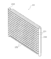
室外熱交換器23は、冷房運転時には室外空気を冷却源とする冷媒の放熱器として機能し、暖房運転時には室外空気を加熱源とする冷媒の蒸発器として機能する熱交換器である。室外熱交換器23は、液側が液冷媒管35に接続されており、ガス側が第1ガス冷媒管33に接続されている。液冷媒管35は、室外熱交換器23の液側と液冷媒連絡管5側とを接続する冷媒管である。室外熱交換器23は、伝熱管として扁平多穴管を使用する熱交換器である。より具体的には、室外熱交換器23は、図2〜図4に示すように、主として、扁平多穴管からなる伝熱管231と、多数の差込フィン232とにより構成された差込フィン式の積層型熱交換器である。扁平多穴管からなる伝熱管231は、アルミニウムまたはアルミニウム合金で成形されており、伝熱面となる上下の平面部と、冷媒が流れる多数の小さな冷媒流路231aを有している。冷媒流路231aとしては、内径が1mm以下の円形又はこれに同等の断面積を有する多角形の流路穴を有するものが使用される。伝熱管231は、平面部を上下に向けた状態で、間隔をあけて複数段配列されており、その両端がヘッダ233、234に接続されている。差込フィン232は、アルミニウム製またはアルミニウム合金製のフィンであり、伝熱管231に接している。両ヘッダ233、234の間に配列された複数段の伝熱管231に対して差込フィン232を差し込めるように、差込フィン232には、水平に細長く延びる複数の切り欠き232aが形成されている。これらの差込フィン232の切り欠き232aの形状は、伝熱管231の断面の外形にほぼ一致している。ヘッダ233、234は、伝熱管231を支持する機能と、冷媒を伝熱管231の冷媒流路231aに導く機能と、冷媒流路231aから出てきた冷媒を集合させる機能とを有している。ヘッダ233は、仕切り板233aによって、内部空間が2つに仕切られている。ヘッダ234は、仕切り板234a、234b、234c、234dによって、内部空間が5つに仕切られている。これらのヘッダ233、234内の各内部空間には、伝熱管231のほかに、冷媒パス間接続管235、236、第2ガス冷媒管33及び液冷媒管35(図2には図示せず)が接続されている。そして、冷房運転において、圧縮機21から吐出された冷凍サイクルにおける高圧のガス冷媒は、第1ガス冷媒管33を介してヘッダ233の上部空間に流入する。そして、ヘッダ233の上部空間に流入したガス冷媒は、伝熱管231を通じて、ヘッダ234の5つの内部空間のうち上の3つの内部空間に送られた後に、それぞれ折り返され、下方に配置されている伝熱管231を通じてヘッダ233の下部空間に送られる。伝熱管231を通過する際に凝縮した冷媒は、ヘッダ233の下部空間から液冷媒管35に流出する。暖房運転においては、冷媒の流れる向きが冷房運転とは逆になる。尚、室外熱交換器23は、上記のような差込フィン式の積層型熱交換器に限定されるものではなく、例えば、図5に示すように、扁平多穴管からなる複数の伝熱管231と多数の波形フィン237とにより構成された波形フィン式の積層型熱交換器であってもよい。ここで、波形フィン237は、波形に折り曲げられたアルミニウム製又はアルミニウム合金製のフィンである。波形フィン237は、上下に隣接する伝熱管231に挟まれた通風空間に配置されており、その谷部及び山部が伝熱管231の平面部と接触している。そして、このような伝熱管231として扁平多穴管を使用している室外熱交換器23は、冷媒を保有可能な容積が小さく、ここでは、室内熱交換器41の冷媒を保有可能な容積よりも小さくなっている。   The outdoor heat exchanger 23 is a heat exchanger that functions as a refrigerant radiator that uses outdoor air as a cooling source during cooling operation, and functions as a refrigerant evaporator that uses outdoor air as a heating source during heating operation. The outdoor heat exchanger 23 has a liquid side connected to the liquid refrigerant pipe 35 and a gas side connected to the first gas refrigerant pipe 33. The liquid refrigerant pipe 35 is a refrigerant pipe that connects the liquid side of the outdoor heat exchanger 23 and the liquid refrigerant communication pipe 5 side. The outdoor heat exchanger 23 is a heat exchanger that uses a flat multi-hole tube as a heat transfer tube. More specifically, as shown in FIGS. 2 to 4, the outdoor heat exchanger 23 is mainly composed of a heat transfer tube 231 composed of a flat multi-hole tube and a large number of insertion fins 232. This is a stacked heat exchanger of the type. The heat transfer tube 231 formed of a flat multi-hole tube is formed of aluminum or an aluminum alloy, and has upper and lower flat portions serving as heat transfer surfaces and a large number of small refrigerant channels 231a through which a refrigerant flows. As the refrigerant channel 231a, a circular channel having an inner diameter of 1 mm or less or a polygonal channel hole having an equivalent cross-sectional area is used. The heat transfer tubes 231 are arranged in a plurality of stages at intervals with the plane portion facing up and down, and both ends thereof are connected to the headers 233 and 234. The insertion fins 232 are aluminum or aluminum alloy fins and are in contact with the heat transfer tubes 231. The insertion fins 232 are formed with a plurality of notches 232a extending horizontally so that the insertion fins 232 can be inserted into the plurality of stages of heat transfer tubes 231 arranged between the headers 233 and 234. Yes. The shape of the notch 232 a of these insertion fins 232 substantially matches the outer shape of the cross section of the heat transfer tube 231. The headers 233 and 234 have a function of supporting the heat transfer tube 231, a function of guiding the refrigerant to the refrigerant flow path 231 a of the heat transfer pipe 231, and a function of collecting the refrigerant that has come out of the refrigerant flow path 231 a. The header 233 is divided into two internal spaces by a partition plate 233a. The header 234 is divided into five internal spaces by partition plates 234a, 234b, 234c, and 234d. In each internal space in these headers 233 and 234, in addition to the heat transfer pipe 231, the refrigerant path connecting pipes 235 and 236, the second gas refrigerant pipe 33 and the liquid refrigerant pipe 35 (not shown in FIG. 2). Is connected. In the cooling operation, the high-pressure gas refrigerant in the refrigeration cycle discharged from the compressor 21 flows into the upper space of the header 233 via the first gas refrigerant pipe 33. Then, the gas refrigerant that has flowed into the upper space of the header 233 is sent to the upper three internal spaces of the five internal spaces of the header 234 through the heat transfer tubes 231 and then folded and disposed below. It is sent to the lower space of the header 233 through the heat transfer tube 231. The refrigerant condensed when passing through the heat transfer tube 231 flows out from the lower space of the header 233 to the liquid refrigerant tube 35. In the heating operation, the direction in which the refrigerant flows is opposite to that in the cooling operation. The outdoor heat exchanger 23 is not limited to the insertion fin type stacked heat exchanger as described above. For example, as shown in FIG. 5, a plurality of heat transfer tubes each formed of a flat multi-hole tube. It may be a corrugated fin type stacked heat exchanger composed of 231 and a large number of corrugated fins 237. Here, the corrugated fins 237 are fins made of aluminum or aluminum alloy bent into a corrugated shape. The corrugated fins 237 are disposed in the ventilation space sandwiched between the heat transfer tubes 231 adjacent in the vertical direction, and the valley portion and the mountain portion thereof are in contact with the flat portion of the heat transfer tube 231. And the outdoor heat exchanger 23 which uses the flat multi-hole pipe | tube as such a heat exchanger tube 231 has a small capacity | capacitance which can hold | maintain a refrigerant | coolant here, The volume which can hold | maintain the refrigerant | coolant of the indoor heat exchanger 41 is here. Is also getting smaller.

レシーバ25は、室外熱交換器23と室内熱交側膨張弁26との間に設けられている。レシーバ25は、冷房運転時に冷凍サイクルにおける高圧になり、室外熱交換器23において放熱した後の冷凍サイクルにおける高圧の冷媒を溜めることが可能な容器である。また、レシーバ25は、暖房運転時に冷凍サイクルにおける低圧になり、室内熱交側膨張弁26において減圧された後の冷凍サイクルにおける低圧の冷媒を溜めることが可能な容器である。   The receiver 25 is provided between the outdoor heat exchanger 23 and the indoor heat exchange side expansion valve 26. The receiver 25 is a container that is capable of storing high-pressure refrigerant in the refrigeration cycle that has become high pressure in the refrigeration cycle during cooling operation and radiates heat in the outdoor heat exchanger 23. The receiver 25 is a container capable of storing a low-pressure refrigerant in the refrigeration cycle that is low in the refrigeration cycle during the heating operation and is decompressed in the indoor heat exchanger side expansion valve 26.

室内熱交側膨張弁26は、冷房運転時には、室外熱交換器23において放熱した冷凍サイクルにおける高圧の冷媒を冷凍サイクルにおける低圧まで減圧する弁である。また、室内熱交側膨張弁26は、暖房運転時には、レシーバ25に溜められた冷凍サイクルにおける高圧の冷媒を冷凍サイクルにおける低圧まで減圧する弁である。室内熱交側膨張弁26は、液冷媒管35の液側閉鎖弁27寄りの部分に設けられている。ここでは、室内熱交側膨張弁26として、電動膨張弁が使用されている。   The indoor heat exchange side expansion valve 26 is a valve that decompresses the high-pressure refrigerant in the refrigeration cycle radiated in the outdoor heat exchanger 23 to the low pressure in the refrigeration cycle during the cooling operation. The indoor heat exchange side expansion valve 26 is a valve that decompresses the high-pressure refrigerant in the refrigeration cycle stored in the receiver 25 to a low pressure in the refrigeration cycle during heating operation. The indoor heat exchange side expansion valve 26 is provided in a portion of the liquid refrigerant pipe 35 near the liquid side closing valve 27. Here, an electric expansion valve is used as the indoor heat exchange side expansion valve 26.

液側閉鎖弁27及びガス側閉鎖弁28は、外部の機器・配管(具体的には、液冷媒連絡管5及びガス冷媒連絡管6)との接続口に設けられた弁である。液側閉鎖弁27は、液冷媒管35の端部に設けられている。ガス側閉鎖弁28は、第2ガス冷媒管34の端部に設けられている。   The liquid side shut-off valve 27 and the gas side shut-off valve 28 are valves provided at connection ports with external devices and pipes (specifically, the liquid refrigerant communication pipe 5 and the gas refrigerant communication pipe 6). The liquid side closing valve 27 is provided at the end of the liquid refrigerant pipe 35. The gas side closing valve 28 is provided at the end of the second gas refrigerant pipe 34.

レシーバガス抜き管30は、レシーバ25内に溜まった冷凍サイクルにおける高圧又は低圧のガス冷媒を圧縮機21の吸入管31に導く冷媒管である。レシーバガス抜き管30は、レシーバ25の上部と吸入管31の途中部分との間を接続するように設けられている。レシーバガス抜き管30には、レシーバガス抜き弁30a、キャピラリーチューブ30b、及び、逆止弁30cが設けられている。レシーバガス抜き弁30aは、レシーバガス抜き管30の冷媒の流れをON/OFFする開閉制御可能な弁であり、ここでは、電磁弁が使用されている。キャピラリーチューブ30bは、レシーバ25内に溜まったガス冷媒を冷凍サイクルにおける低圧まで減圧する機構であり、ここでは、レシーバガス抜き管よりも細径のキャピラリーチューブが使用されている。逆止弁30cは、レシーバ25側から吸入管31側への冷媒の流れのみを許容する弁機構であり、ここでは、逆止弁が使用されている。   The receiver degassing pipe 30 is a refrigerant pipe that guides high-pressure or low-pressure gas refrigerant in the refrigeration cycle accumulated in the receiver 25 to the suction pipe 31 of the compressor 21. The receiver degassing pipe 30 is provided so as to connect between the upper part of the receiver 25 and the middle part of the suction pipe 31. The receiver gas vent pipe 30 is provided with a receiver gas vent valve 30a, a capillary tube 30b, and a check valve 30c. The receiver degassing valve 30a is a valve that can be opened and closed to turn on / off the refrigerant flow in the receiver degassing pipe 30, and here, an electromagnetic valve is used. The capillary tube 30b is a mechanism that depressurizes the gas refrigerant accumulated in the receiver 25 to a low pressure in the refrigeration cycle, and here, a capillary tube having a diameter smaller than that of the receiver degassing tube is used. The check valve 30c is a valve mechanism that allows only the flow of refrigerant from the receiver 25 side to the suction pipe 31 side, and a check valve is used here.

室外ユニット2は、室外ユニット2内に室外空気を吸入して、室外熱交換器23において冷媒と熱交換させた後に、外部に排出するための室外ファン36を有している。すなわち、室外ユニット2は、室外熱交換器23を流れる冷媒の冷却源又は加熱源としての室外空気を室外熱交換器23に供給するファンとして、室外ファン36を有している。ここでは、室外ファン36として、室外ファン用モータ37によって駆動されるプロペラファン等が使用されている。また、室外ファン用モータ37は、インバータ等によって回転数を変更することができるようになっている。   The outdoor unit 2 has an outdoor fan 36 for sucking outdoor air into the outdoor unit 2 and exchanging heat with the refrigerant in the outdoor heat exchanger 23 and then discharging the air to the outside. That is, the outdoor unit 2 includes an outdoor fan 36 as a fan that supplies outdoor air as a cooling source or a heating source of the refrigerant flowing through the outdoor heat exchanger 23 to the outdoor heat exchanger 23. Here, a propeller fan or the like driven by an outdoor fan motor 37 is used as the outdoor fan 36. Moreover, the motor 37 for outdoor fans can change the rotation speed by an inverter or the like.

室外ユニット2には、各種のセンサが設けられている。具体的には、吸入管31には、圧縮機21に吸入される冷凍サイクルにおける低圧の冷媒の温度Tsを検出する吸入温度センサ51が設けられている。ここでは、吸入温度センサ51は、吸入管31のレシーバガス抜き管30との合流部分よりも下流側の位置に設けられている。吐出管32には、圧縮機21から吐出される冷凍サイクルにおける高圧の冷媒の温度Tdを検出する吐出温度センサ52が設けられている。室外熱交換器23には、室外熱交換器23の中間部分における冷媒の温度Tormを検出する室外熱交中間温度センサ53と、室外熱交換器23の液側における冷媒の温度Torlを検出する室外熱交液側温度センサ54とが設けられている。室外ユニット2には、室外ユニット2内に吸入される室外空気の温度Toaを検出する室外温度センサ55が設けられている。液冷媒管35には、室内熱交側膨張弁26の室内寄りの部分における冷媒の液管温度Tlpを検出する液管温度センサ56が設けられている。   Various types of sensors are provided in the outdoor unit 2. Specifically, the suction pipe 31 is provided with a suction temperature sensor 51 that detects the temperature Ts of the low-pressure refrigerant in the refrigeration cycle sucked into the compressor 21. Here, the suction temperature sensor 51 is provided at a position downstream of the joining portion of the suction pipe 31 and the receiver degassing pipe 30. The discharge pipe 32 is provided with a discharge temperature sensor 52 that detects the temperature Td of the high-pressure refrigerant in the refrigeration cycle discharged from the compressor 21. The outdoor heat exchanger 23 includes an outdoor heat exchange intermediate temperature sensor 53 that detects a refrigerant temperature Torm in an intermediate portion of the outdoor heat exchanger 23, and an outdoor that detects a refrigerant temperature Torl on the liquid side of the outdoor heat exchanger 23. A heat exchanger side temperature sensor 54 is provided. The outdoor unit 2 is provided with an outdoor temperature sensor 55 that detects the temperature Toa of the outdoor air sucked into the outdoor unit 2. The liquid refrigerant pipe 35 is provided with a liquid pipe temperature sensor 56 that detects a liquid pipe temperature Tlp of the refrigerant in a portion of the indoor heat exchange side expansion valve 26 closer to the room.

室外ユニット2は、室外ユニット2を構成する各部の動作を制御する室外側制御部38を有している。そして、室外側制御部38は、室外ユニット2の制御を行うために設けられたマイクロコンピュータやメモリ等を有しており、室内ユニット4(すなわち、室内側制御部44)との間で伝送線8aを介して制御信号等のやりとりを行うことができるようになっている。   The outdoor unit 2 includes an outdoor side control unit 38 that controls the operation of each unit constituting the outdoor unit 2. The outdoor control unit 38 includes a microcomputer, a memory, and the like provided for controlling the outdoor unit 2, and a transmission line between the indoor unit 4 (that is, the indoor control unit 44). Control signals and the like can be exchanged via 8a.

<冷媒連絡管>
冷媒連絡管5、6は、空気調和装置1を建物等の設置場所に設置する際に、現地にて施工される冷媒管であり、設置場所や室外ユニットと室内ユニットとの組み合わせ等の設置条件に応じて種々の長さや管径を有するものが使用される。
<Refrigerant communication pipe>
Refrigerant communication pipes 5 and 6 are refrigerant pipes constructed on site when the air conditioner 1 is installed at an installation location such as a building, and installation conditions such as the installation location and a combination of an outdoor unit and an indoor unit. Those having various lengths and tube diameters are used.

以上のように、室外ユニット2と、室内ユニット4と、冷媒連絡管5、6とが接続されることによって、空気調和装置1の冷媒回路10が構成されている。空気調和装置1は、四路切換弁22を冷房サイクル状態に切り換えることによって、圧縮機21、室外熱交換器23、室内熱交側膨張弁26、室内熱交換器41の順に冷媒を循環させるとともに室外ファン36を駆動させて冷房運転を行うようになっている。また、空気調和装置1は、四路切換弁22を暖房サイクル状態に切り換えることによって、圧縮機21、室内熱交換器41、室内熱交側膨張弁26、室外熱交換器23の順に冷媒を循環させるとともに室外ファン36を駆動させて暖房運転を行うようになっている。また、室外熱交換器23は、伝熱管231として扁平多穴管を使用する熱交換器であり、室外熱交換器23と室内熱交側膨張弁26との間には、レシーバ25が設けられている。   As described above, the refrigerant circuit 10 of the air conditioner 1 is configured by connecting the outdoor unit 2, the indoor unit 4, and the refrigerant communication pipes 5 and 6. The air conditioner 1 circulates the refrigerant in the order of the compressor 21, the outdoor heat exchanger 23, the indoor heat exchange side expansion valve 26, and the indoor heat exchanger 41 by switching the four-way switching valve 22 to the cooling cycle state. The outdoor fan 36 is driven to perform a cooling operation. The air conditioner 1 circulates the refrigerant in the order of the compressor 21, the indoor heat exchanger 41, the indoor heat exchanger side expansion valve 26, and the outdoor heat exchanger 23 by switching the four-way switching valve 22 to the heating cycle state. The outdoor fan 36 is driven and the heating operation is performed. The outdoor heat exchanger 23 is a heat exchanger that uses a flat multi-hole tube as the heat transfer tube 231, and a receiver 25 is provided between the outdoor heat exchanger 23 and the indoor heat exchanger side expansion valve 26. ing.

<制御部>
空気調和装置1は、室内側制御部44と室外側制御部38とから構成される制御部8によって、室外ユニット2及び室内ユニット4の各機器の制御を行うことができるようになっている。すなわち、室内側制御部44と室外側制御部38との間を接続する伝送線8aとによって、上記の冷房運転や暖房運転等を含む空気調和装置1全体の運転制御を行う制御部8が構成されている。
<Control unit>
The air conditioner 1 can control each device of the outdoor unit 2 and the indoor unit 4 by the control unit 8 including the indoor side control unit 44 and the outdoor side control unit 38. That is, the control unit 8 that performs operation control of the entire air conditioner 1 including the cooling operation and the heating operation described above is configured by the transmission line 8a that connects between the indoor side control unit 44 and the outdoor side control unit 38. Has been.

制御部8は、図6に示すように、各種センサ51〜59等の検出信号を受けることができるように接続されるとともに、これらの検出信号等に基づいて各種機器及び弁21a、22、26、30a、37、43等を制御することができるように接続されている。   As shown in FIG. 6, the control unit 8 is connected so as to receive detection signals from various sensors 51 to 59 and the like, and based on these detection signals and the like, various devices and valves 21 a, 22, and 26. , 30a, 37, 43, etc. are connected so that they can be controlled.

(2)空気調和装置の基本動作
次に、空気調和装置1の基本動作(後述の暖房停止制御を除く動作)について、図1を用いて説明する。空気調和装置1は、基本動作として、冷房運転及び暖房運転を行うことが可能である。
(2) Basic operation | movement of an air conditioning apparatus Next, the basic operation | movement (operation | movement except the heating stop control mentioned later) of the air conditioning apparatus 1 is demonstrated using FIG. The air conditioner 1 can perform a cooling operation and a heating operation as basic operations.

<暖房運転>
暖房運転時には、四路切換弁22が暖房サイクル状態(図1の破線で示される状態)に切り換えられる。
<Heating operation>
During the heating operation, the four-way switching valve 22 is switched to the heating cycle state (the state indicated by the broken line in FIG. 1).

冷媒回路10において、冷凍サイクルにおける低圧のガス冷媒は、圧縮機21に吸入され、冷凍サイクルにおける高圧になるまで圧縮された後に吐出される。   In the refrigerant circuit 10, the low-pressure gas refrigerant in the refrigeration cycle is sucked into the compressor 21 and is discharged after being compressed to a high pressure in the refrigeration cycle.

圧縮機21から吐出された高圧のガス冷媒は、四路切換弁22、ガス側閉鎖弁28及びガス冷媒連絡管6を通じて、室内熱交換器41に送られる。   The high-pressure gas refrigerant discharged from the compressor 21 is sent to the indoor heat exchanger 41 through the four-way switching valve 22, the gas side closing valve 28 and the gas refrigerant communication pipe 6.

室内熱交換器41に送られた高圧のガス冷媒は、室内熱交換器41において、室内ファン42によって冷却源として供給される室内空気と熱交換を行って放熱して、高圧の液冷媒になる。これにより、室内空気は加熱され、その後に、室内に供給されることで室内の暖房が行われる。   The high-pressure gas refrigerant sent to the indoor heat exchanger 41 radiates heat by exchanging heat with indoor air supplied as a cooling source by the indoor fan 42 in the indoor heat exchanger 41 to become a high-pressure liquid refrigerant. . Thereby, indoor air is heated, and indoor heating is performed by being supplied indoors after that.

室内熱交換器41で放熱した高圧の液冷媒は、液冷媒連絡管5及び液側閉鎖弁27を通じて、室内熱交側膨張弁26に送られる。   The high-pressure liquid refrigerant radiated by the indoor heat exchanger 41 is sent to the indoor heat exchange side expansion valve 26 through the liquid refrigerant communication pipe 5 and the liquid side closing valve 27.

室内熱交側膨張弁26に送られた高圧の液冷媒は、室内熱交側膨張弁26によって冷凍サイクルにおける低圧まで減圧される。室内熱交側膨張弁26で減圧された低圧の冷媒は、レシーバ25に送られて気液分離される。そして、レシーバ25内において気液分離されたガス冷媒は、レシーバガス抜き弁30aを開けることによってレシーバガス抜き管30を通じて吸入管31に送られる。また、レシーバ25内において気液分離された液冷媒は、室外熱交換器23に送られる。   The high-pressure liquid refrigerant sent to the indoor heat exchange side expansion valve 26 is decompressed to a low pressure in the refrigeration cycle by the indoor heat exchange side expansion valve 26. The low-pressure refrigerant decompressed by the indoor heat exchange side expansion valve 26 is sent to the receiver 25 for gas-liquid separation. The gas refrigerant separated in the receiver 25 is sent to the suction pipe 31 through the receiver gas vent pipe 30 by opening the receiver gas vent valve 30a. Further, the liquid refrigerant separated from the gas and liquid in the receiver 25 is sent to the outdoor heat exchanger 23.

室外熱交換器23に送られた低圧の液冷媒は、室外熱交換器23において、室外ファン36によって加熱源として供給される室外空気と熱交換を行って蒸発して、低圧のガス冷媒になる。   The low-pressure liquid refrigerant sent to the outdoor heat exchanger 23 evaporates by exchanging heat with outdoor air supplied as a heating source by the outdoor fan 36 in the outdoor heat exchanger 23 to become a low-pressure gas refrigerant. .

室外熱交換器23で蒸発した低圧の冷媒は、四路切換弁22を通じて、吸入管31に送られて、レシーバガス抜き管30から流入するガス冷媒と合流して、再び、圧縮機21に吸入される。   The low-pressure refrigerant evaporated in the outdoor heat exchanger 23 is sent to the suction pipe 31 through the four-way switching valve 22, merges with the gas refrigerant flowing in from the receiver degassing pipe 30, and sucked into the compressor 21 again. Is done.

<冷房運転>
冷房運転時には、四路切換弁22が冷房サイクル状態(図1の実線で示される状態)に切り換えられる。
<Cooling operation>
During the cooling operation, the four-way switching valve 22 is switched to the cooling cycle state (state indicated by the solid line in FIG. 1).

冷媒回路10において、冷凍サイクルにおける低圧のガス冷媒は、圧縮機21に吸入され、冷凍サイクルにおける高圧になるまで圧縮された後に吐出される。   In the refrigerant circuit 10, the low-pressure gas refrigerant in the refrigeration cycle is sucked into the compressor 21 and is discharged after being compressed to a high pressure in the refrigeration cycle.

圧縮機21から吐出された高圧のガス冷媒は、四路切換弁22を通じて、室外熱交換器23に送られる。   The high-pressure gas refrigerant discharged from the compressor 21 is sent to the outdoor heat exchanger 23 through the four-way switching valve 22.

室外熱交換器23に送られた高圧のガス冷媒は、室外熱交換器23において、室外ファン36によって冷却源として供給される室外空気と熱交換を行って放熱して、高圧の液冷媒になる。   The high-pressure gas refrigerant sent to the outdoor heat exchanger 23 performs heat exchange with the outdoor air supplied as a cooling source by the outdoor fan 36 in the outdoor heat exchanger 23 to dissipate heat to become a high-pressure liquid refrigerant. .

室外熱交換器23において放熱した高圧の液冷媒は、レシーバ25に送られて気液分離される。そして、レシーバ25内において気液分離されたガス冷媒は、レシーバガス抜き弁30aを開けることによってレシーバガス抜き管30を通じて吸入管31に送られる。また、レシーバ25内において気液分離された液冷媒は、室内熱交側膨張弁26に送られる。   The high-pressure liquid refrigerant that has radiated heat in the outdoor heat exchanger 23 is sent to the receiver 25 for gas-liquid separation. The gas refrigerant separated in the receiver 25 is sent to the suction pipe 31 through the receiver gas vent pipe 30 by opening the receiver gas vent valve 30a. Further, the liquid refrigerant separated in the receiver 25 is sent to the indoor heat exchange side expansion valve 26.

室内熱交側膨張弁26に送られた高圧の液冷媒は、室内熱交側膨張弁26によって冷凍サイクルにおける低圧まで減圧される。室内熱交側膨張弁26で減圧された冷媒は、液側閉鎖弁27及び液冷媒連絡管5を通じて、室内熱交換器41に送られる。   The high-pressure liquid refrigerant sent to the indoor heat exchange side expansion valve 26 is decompressed to a low pressure in the refrigeration cycle by the indoor heat exchange side expansion valve 26. The refrigerant decompressed by the indoor heat exchange side expansion valve 26 is sent to the indoor heat exchanger 41 through the liquid side closing valve 27 and the liquid refrigerant communication pipe 5.

室内熱交換器41に送られた低圧の冷媒は、室内熱交換器41において、室内ファン42によって加熱源として供給される室内空気と熱交換を行って蒸発する。これにより、室内空気は冷却され、その後に、室内に供給されることで室内の冷房が行われる。   The low-pressure refrigerant sent to the indoor heat exchanger 41 evaporates by exchanging heat with indoor air supplied as a heating source by the indoor fan 42 in the indoor heat exchanger 41. As a result, the room air is cooled and then supplied to the room to cool the room.

室内熱交換器41において蒸発した低圧のガス冷媒は、ガス冷媒連絡管6、ガス側閉鎖弁28及び四路切換弁22を通じて、吸入管31に送られて、レシーバガス抜き管30から流入するガス冷媒と合流して、再び、圧縮機21に吸入される。   The low-pressure gas refrigerant evaporated in the indoor heat exchanger 41 is sent to the suction pipe 31 through the gas refrigerant communication pipe 6, the gas side closing valve 28 and the four-way switching valve 22, and flows into the receiver gas vent pipe 30. The refrigerant merges with the refrigerant and is sucked into the compressor 21 again.

(3)暖房停止制御
上記暖房運転をサーモオフやリモコンからの指令等によって停止する際において、四路切換弁22を暖房サイクル状態のままで、圧縮機21を停止させると、暖房運転を停止する際の冷媒回路10内の冷媒の流れによって、室外熱交換器23の伝熱管231としての扁平多穴管内に溜まった液冷媒が、圧縮機21の吸入側に押し流されることになる。そして、その後に、暖房運転を再開すると、圧縮機21が液冷媒を吸入するおそれがある。
(3) Heating stop control When the heating operation is stopped by a thermo-off, a command from a remote controller, or the like, when the compressor 21 is stopped while the four-way switching valve 22 remains in the heating cycle state, the heating operation is stopped. Due to the refrigerant flow in the refrigerant circuit 10, the liquid refrigerant accumulated in the flat multi-hole tube as the heat transfer tube 231 of the outdoor heat exchanger 23 is pushed away to the suction side of the compressor 21. Then, when the heating operation is resumed thereafter, the compressor 21 may suck liquid refrigerant.

ここで、四路切換弁によって冷房運転と暖房運転とを切り換えて行う空気調和装置では、暖房運転時に室外熱交換器が冷媒の蒸発器として機能する。このため、暖房運転を停止する際には、室外熱交換器の伝熱管として円管を使用しても、又は、扁平多穴管を使用しても、室外熱交換器の伝熱管内に液冷媒が溜まることになる。   Here, in an air conditioner that switches between a cooling operation and a heating operation by a four-way switching valve, the outdoor heat exchanger functions as a refrigerant evaporator during the heating operation. For this reason, when stopping the heating operation, even if a circular tube is used as the heat transfer tube of the outdoor heat exchanger or a flat multi-hole tube is used, the liquid is put in the heat transfer tube of the outdoor heat exchanger. The refrigerant will accumulate.

しかし、伝熱管として円管を使用する室外熱交換器を採用する場合には、四路切換弁を暖房サイクル状態のままで圧縮機を停止しても、暖房運転の停止後の冷媒回路内の冷媒の流れによって、円管内に溜まった液冷媒は、圧縮機の吸入側にほとんど押し流されることはない。なぜなら、伝熱管として円管を使用する場合には、円管の下部空間に液冷媒が流れ、円管の上部空間にガス冷媒が流れるため、暖房運転の停止後に膨張弁側から室外熱交換器に冷媒が流入しても、主として、円管の上部空間に存在するガス冷媒が押し出されるからである。   However, when an outdoor heat exchanger that uses a circular pipe as the heat transfer pipe is adopted, even if the compressor is stopped with the four-way switching valve in the heating cycle state, the refrigerant circuit in the refrigerant circuit after the heating operation is stopped is used. Due to the flow of the refrigerant, the liquid refrigerant accumulated in the circular pipe is hardly pushed away to the suction side of the compressor. This is because when a circular pipe is used as the heat transfer pipe, liquid refrigerant flows in the lower space of the circular pipe and gas refrigerant flows in the upper space of the circular pipe. Therefore, the outdoor heat exchanger from the expansion valve side after the heating operation is stopped. This is because even if the refrigerant flows into the gas, the gas refrigerant present in the upper space of the circular pipe is mainly pushed out.

これに対して、本実施形態のように、伝熱管231として扁平多穴管を使用する室外熱交換器23を採用する場合には、扁平多穴管に形成された多数の小さな冷媒流路231a内が液冷媒によってほとんど満たされてしまい、ガス冷媒が流れる空間がほとんど形成されない。このため、伝熱管231として扁平多穴管を使用する室外熱交換器23を採用する場合には、四路切換弁22を暖房サイクル状態のままで圧縮機21を停止すると、暖房運転の停止後の室内熱交側膨張弁26側から室外熱交換器23への冷媒の流れによって、扁平多穴管内に溜まった液冷媒は、圧縮機21の吸入側に押し流されてしまう。特に、ここでは、室外熱交換器23の容積が小さいため、四路切換弁22を暖房サイクル状態のままで圧縮機21を停止すると、暖房運転の停止後の室内側膨張弁26側から室外熱交換器23への冷媒の流れの影響を大きく受けることになり、室外熱交換器23を構成する扁平多穴管からなる伝熱管231内に溜まった液冷媒は、圧縮機21の吸入側にさらに押し流されやすくなっている。   On the other hand, when the outdoor heat exchanger 23 that uses a flat multi-hole tube as the heat transfer tube 231 is employed as in the present embodiment, a large number of small refrigerant channels 231a formed in the flat multi-hole tube. The inside is almost filled with the liquid refrigerant, and a space through which the gas refrigerant flows is hardly formed. For this reason, when the outdoor heat exchanger 23 using a flat multi-hole tube as the heat transfer tube 231 is employed, if the compressor 21 is stopped while the four-way switching valve 22 remains in the heating cycle state, the heating operation is stopped. Due to the flow of the refrigerant from the indoor heat exchange side expansion valve 26 side to the outdoor heat exchanger 23, the liquid refrigerant accumulated in the flat multi-hole tube is pushed away to the suction side of the compressor 21. In particular, since the volume of the outdoor heat exchanger 23 is small here, if the compressor 21 is stopped while the four-way switching valve 22 remains in the heating cycle state, the outdoor heat from the indoor expansion valve 26 side after the heating operation is stopped. The liquid refrigerant that is greatly influenced by the flow of the refrigerant to the exchanger 23 and is accumulated in the heat transfer pipe 231 formed of a flat multi-hole pipe constituting the outdoor heat exchanger 23 further flows to the suction side of the compressor 21. It is easy to be washed away.

そこで、本実施形態の空気調和装置1では、以下のように、暖房運転の停止時に行われる暖房停止制御において、伝熱管231の型式による暖房運転の停止後の冷媒挙動の相違を考慮して、暖房運転を停止する際に、室外熱交換器23と室内熱交側膨張弁26との間にレシーバ25を設けて、暖房運転を停止する際に、四路切換弁22を暖房サイクル状態から冷房サイクル状態に切り換えて、レシーバ25に冷媒を強制的に溜めるレシーバ液溜め制御を行い、その後に、圧縮機21を停止させるようにしている。   Therefore, in the air conditioning apparatus 1 of the present embodiment, in the heating stop control performed when the heating operation is stopped, the difference in refrigerant behavior after the stop of the heating operation due to the type of the heat transfer tube 231 is considered as follows. When stopping the heating operation, the receiver 25 is provided between the outdoor heat exchanger 23 and the indoor heat exchange side expansion valve 26, and when stopping the heating operation, the four-way switching valve 22 is cooled from the heating cycle state. By switching to the cycle state, the receiver liquid reservoir control for forcibly storing the refrigerant in the receiver 25 is performed, and then the compressor 21 is stopped.

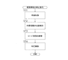
次に、本実施形態における暖房停止制御について、図7及び図8を用いて説明する。ここで、図7は、暖房停止制御のフローチャートである。図8は、暖房停止制御時の圧縮機21、室外ファン36、室内ファン42、四路切換弁22、室内熱交側膨張弁26、及び、レシーバガス抜き弁30aの動作を示すタイムチャートである。尚、以下に説明する暖房停止制御は、上記の基本動作と同様、制御部8が行う。   Next, the heating stop control in this embodiment is demonstrated using FIG.7 and FIG.8. Here, FIG. 7 is a flowchart of the heating stop control. FIG. 8 is a time chart showing operations of the compressor 21, the outdoor fan 36, the indoor fan 42, the four-way switching valve 22, the indoor heat exchange side expansion valve 26, and the receiver degassing valve 30a during the heating stop control. . Note that the heating stop control described below is performed by the control unit 8 as in the above basic operation.

<ステップST1>
サーモオフやリモコン(図示せず)等によって暖房運転の停止指令がなされると、制御部8は、まず、ステップST1の準備制御を行う(図8の時間t1の間の処理を参照)。ステップST1では、圧縮機21の回転数を徐々に減少させる。ここでは、圧縮機21の回転数を最低回転数Nminまで減少させるようにしている。また、このとき、室外ファン36及び室内ファン42の運転を継続する。但し、室内ファン42は、室内へのコールドドラフトを避けるために、ステップST1〜ST4の暖房停止制御の間、最小風量に設定される。
<Step ST1>
When a heating operation stop command is issued by a thermo-off, a remote controller (not shown), or the like, the control unit 8 first performs a preparation control in step ST1 (see the process during time t1 in FIG. 8). In step ST1, the rotation speed of the compressor 21 is gradually decreased. Here, the rotational speed of the compressor 21 is reduced to the minimum rotational speed Nmin. At this time, the operation of the outdoor fan 36 and the indoor fan 42 is continued. However, the indoor fan 42 is set to the minimum air volume during the heating stop control in steps ST1 to ST4 in order to avoid a cold draft into the room.

そして、ステップST1の準備制御を行った後に、ステップST2の処理に移行する。   And after performing preparation control of step ST1, it transfers to the process of step ST2.

<ステップST2>
次に、制御部8は、ステップST2の四路切換弁切換制御、すなわち、四路切換弁22を暖房サイクル状態から冷房サイクル状態に切り換える制御を行う(図8の時間t2の間の処理を参照)。ステップST2では、まず、圧縮機21の回転数を最低回転数Nminに維持したままで、室内熱交側膨張弁26を全閉にする。ここで、例えば、室内熱交側膨張弁26を開けたままで四路切換弁22を暖房サイクル状態から冷房サイクル状態に切り換えると、室内熱交側膨張弁26を通じて室外熱交換器23側から室内熱交換器41側に向かう冷媒の流れが急激に発生することになる。これによって、暖房運転時に冷媒の放熱器として機能していた室内熱交換器41に溜まった液冷媒が、圧縮機21の吸入側に送られるおそれがある。しかし、ここでは、上記のように、四路切換弁22を暖房サイクル状態から冷房サイクル状態に切り換える前に室内熱交側膨張弁26を全閉にしているため、四路切換弁22を暖房サイクル状態から冷房サイクル状態に切り換えても、室内熱交側膨張弁26を通じて室外熱交換器23側から室内熱交換器41側に向かう冷媒の流れが発生せず、暖房運転時に冷媒の放熱器として機能していた室内熱交換器41に溜まった液冷媒が、圧縮機21の吸入側に送られることはない。
<Step ST2>
Next, the control unit 8 performs the four-way switching valve switching control in step ST2, that is, the control for switching the four-way switching valve 22 from the heating cycle state to the cooling cycle state (see the process during the time t2 in FIG. 8). ). In step ST2, first, the indoor heat exchange side expansion valve 26 is fully closed while the rotation speed of the compressor 21 is maintained at the minimum rotation speed Nmin. Here, for example, if the four-way switching valve 22 is switched from the heating cycle state to the cooling cycle state while the indoor heat exchange side expansion valve 26 is kept open, the indoor heat is transferred from the outdoor heat exchanger 23 side through the indoor heat exchange side expansion valve 26. A refrigerant flow toward the exchanger 41 side is abruptly generated. Thereby, the liquid refrigerant accumulated in the indoor heat exchanger 41 functioning as a refrigerant radiator during the heating operation may be sent to the suction side of the compressor 21. However, since the indoor heat exchange side expansion valve 26 is fully closed before switching the four-way switching valve 22 from the heating cycle state to the cooling cycle state as described above, the four-way switching valve 22 is set to the heating cycle. Even when switching from the state to the cooling cycle state, the refrigerant flow from the outdoor heat exchanger 23 side to the indoor heat exchanger 41 side does not occur through the indoor heat exchange side expansion valve 26 and functions as a refrigerant radiator during heating operation. The liquid refrigerant accumulated in the indoor heat exchanger 41 is not sent to the suction side of the compressor 21.

そして、室内熱交側膨張弁26を全閉にした後に、四路切換弁22を暖房サイクル状態から冷房サイクル状態に切り換える。これにより、室内熱交側膨張弁26が全閉された状態において、冷房運転と同様の冷媒の流れが発生し、レシーバ25に液冷媒を溜めることができる状態になる。ここで、四路切換弁22を暖房サイクル状態から冷房サイクル状態に切り換える際には、圧縮機21の回転数を一時的に増加させるようにしている。ここでは、圧縮機21の回転数を最低回転数Nminから最大回転数Nmaxよりも少し小さい四路切換弁切換回転数Nchまで一時的に増加させるようにしている。これにより、四路切換弁22の4つのポート間における高低差圧を大きくすることができるようになり、確実に四路切換弁22の切り換えを行うことができる。また、ここでは、レシーバガス抜き弁30aも全開される。   Then, after the indoor heat exchange side expansion valve 26 is fully closed, the four-way switching valve 22 is switched from the heating cycle state to the cooling cycle state. Thereby, in the state in which the indoor heat exchange side expansion valve 26 is fully closed, the same refrigerant flow as in the cooling operation is generated, and the liquid refrigerant can be stored in the receiver 25. Here, when the four-way switching valve 22 is switched from the heating cycle state to the cooling cycle state, the rotational speed of the compressor 21 is temporarily increased. Here, the rotational speed of the compressor 21 is temporarily increased from the minimum rotational speed Nmin to the four-way switching valve switching rotational speed Nch that is slightly smaller than the maximum rotational speed Nmax. As a result, the pressure difference between the four ports of the four-way switching valve 22 can be increased, and the four-way switching valve 22 can be switched reliably. Here, the receiver degassing valve 30a is also fully opened.

そして、ステップST2の四路切換弁切換制御を行った後、すなわち、四路切換弁22が暖房サイクル状態から冷房サイクル状態に切り換わった後に、ステップST3の処理に移行する。   Then, after performing the four-way switching valve switching control in step ST2, that is, after the four-way switching valve 22 is switched from the heating cycle state to the cooling cycle state, the process proceeds to step ST3.

<ステップST3>
次に、制御部8は、ステップST3のレシーバ液溜め制御を行う(図8の時間t3の間の処理を参照)。レシーバ液溜め制御は、ステップST2において、室内熱交側膨張弁26が全閉された状態において、四路切換弁22の暖房サイクル状態から冷房サイクル状態への切り換えが完了することによって実質的に開始されるが、ステップST3では、さらに、圧縮機21の四路切換弁切換回転数Nchよりも小さい液溜め制御回転数Nlsに設定する。これにより、圧縮機21の過熱焼けを防ぎつつレシーバ25への液溜めを進行させることができる。また、レシーバ液溜め制御時において、レシーバガス抜き弁30aは、レシーバ25への液溜めを促進するために全開される。さらに、レシーバ液溜め制御時において、室外ファン36は、レシーバ25への液溜めを促進するために、最大風量に設定される。このようにして、暖房運転時に室外熱交換器23内に溜まった液冷媒がレシーバ25に排出されて、レシーバ25に溜められることになる。このレシーバ25への液溜めが終了すると、圧縮機21を停止する。また、レシーバガス抜き弁30aを全閉して、レシーバ25内に冷媒が溜まった状態が保持されるようにする。
<Step ST3>
Next, the control part 8 performs receiver liquid reservoir control of step ST3 (refer the process between time t3 of FIG. 8). In step ST2, the receiver liquid reservoir control is substantially started when the switching of the four-way switching valve 22 from the heating cycle state to the cooling cycle state is completed in a state where the indoor heat exchange side expansion valve 26 is fully closed. However, in step ST3, the reservoir control rotation speed Nls is set smaller than the four-way switching valve switching rotation speed Nch of the compressor 21. Thereby, the liquid reservoir to the receiver 25 can be advanced while preventing overheating of the compressor 21. Further, at the time of receiver liquid reservoir control, the receiver gas vent valve 30 a is fully opened to promote the liquid reservoir to the receiver 25. Further, during the receiver liquid reservoir control, the outdoor fan 36 is set to the maximum air volume in order to promote the liquid reservoir to the receiver 25. Thus, the liquid refrigerant accumulated in the outdoor heat exchanger 23 during the heating operation is discharged to the receiver 25 and accumulated in the receiver 25. When the liquid storage in the receiver 25 is completed, the compressor 21 is stopped. Further, the receiver gas vent valve 30a is fully closed so that the state in which the refrigerant is accumulated in the receiver 25 is maintained.

そして、ステップST3のレシーバ液溜め制御を行った後、ステップST4の処理に移行する。   And after performing receiver liquid reservoir control of step ST3, it transfers to the process of step ST4.

<ステップST4>
次に、制御部8は、ステップST4の均圧制御、すなわち、冷媒回路10の高圧部分における圧力を低下させる制御を行う(図8の時間t4の間の処理を参照)。ステップST4では、レシーバ25への液溜めが終了して圧縮機21を停止した後においても、室外ファン36の運転を継続する。これにより、室外熱交換器23における冷媒の圧力が低下し、冷媒回路10の高圧部分(ここでは、圧縮機21の吐出側から室内熱交側膨張弁26までの部分)における圧力が低下する。この均圧制御が終了すると、室外ファン36及び室内ファン42を停止する。
<Step ST4>
Next, the control unit 8 performs pressure equalization control in step ST4, that is, control for reducing the pressure in the high pressure portion of the refrigerant circuit 10 (see the process during the time t4 in FIG. 8). In step ST4, the operation of the outdoor fan 36 is continued even after the liquid storage in the receiver 25 is completed and the compressor 21 is stopped. Thereby, the pressure of the refrigerant | coolant in the outdoor heat exchanger 23 falls, and the pressure in the high voltage | pressure part (here the part from the discharge side of the compressor 21 to the indoor heat exchanger side expansion valve 26) falls. When this pressure equalization control ends, the outdoor fan 36 and the indoor fan 42 are stopped.

以上に説明した暖房停止制御においては、暖房運転を停止する際に、四路切換弁22を暖房サイクル状態から冷房サイクル状態に切り換えて、レシーバ25に冷媒を強制的に溜めるレシーバ液溜め制御を行い、その後に、圧縮機21を停止させるようにしている。   In the heating stop control described above, when the heating operation is stopped, the four-way switching valve 22 is switched from the heating cycle state to the cooling cycle state, and the receiver liquid reservoir control for forcibly storing the refrigerant in the receiver 25 is performed. Then, the compressor 21 is stopped.

これにより、冷房サイクル状態に切り換えられた四路切換弁22によって、暖房運転の停止後の室内熱交側膨張弁26側から室外熱交換器23への冷媒の流れを発生しないようにするとともに、レシーバ液溜め制御によって、暖房運転時に室外熱交換器23内に溜まった液冷媒がレシーバ25に排出されることになる。このため、暖房運転時に室外熱交換器23の扁平多穴管からなる伝熱管231内に溜まった液冷媒が、暖房運転の停止後に圧縮機21の吸入側に押し流されにくくなるとともに、暖房運転の停止後に室外熱交換器23の扁平多穴管からなる伝熱管231内にほとんど溜まり込んでいない状態になる。   Thus, the four-way switching valve 22 switched to the cooling cycle state prevents the refrigerant from flowing from the indoor heat exchange side expansion valve 26 side after the heating operation is stopped to the outdoor heat exchanger 23, and The liquid refrigerant accumulated in the outdoor heat exchanger 23 during the heating operation is discharged to the receiver 25 by the receiver liquid reservoir control. For this reason, the liquid refrigerant accumulated in the heat transfer tube 231 formed of a flat multi-hole tube of the outdoor heat exchanger 23 during the heating operation is less likely to be pushed to the suction side of the compressor 21 after the heating operation is stopped, After stopping, the outdoor heat exchanger 23 is hardly accumulated in the heat transfer tube 231 formed of a flat multi-hole tube.

このように、暖房運転を停止する際に、四路切換弁22を冷房サイクル状態に切り換えてレシーバ液溜め制御を行うことによって、伝熱管231として扁平多穴管を使用する熱交換器を室外熱交換器23として採用しても(さらには、室外熱交換器23の容積が小さい場合であっても)、暖房運転の再開時に、圧縮機21が液冷媒を吸入しにくくすることができる。   As described above, when the heating operation is stopped, the four-way switching valve 22 is switched to the cooling cycle state and the receiver liquid reservoir control is performed, so that the heat exchanger using the flat multi-hole tube as the heat transfer tube 231 is heated to the outdoor heat. Even if it is adopted as the exchanger 23 (and even when the volume of the outdoor heat exchanger 23 is small), the compressor 21 can be made difficult to suck the liquid refrigerant when the heating operation is resumed.

(4)変形例1
上記の実施形態(図1参照)では、冷媒回路10において、レシーバ25と液側閉鎖弁27との間(すなわち、室内熱交換器41側)のみに、室内熱交側膨張弁26が設けられている。これにより、レシーバ25は、冷房運転時に冷凍サイクルにおける高圧になり、室外熱交換器23において放熱した後の冷凍サイクルにおける高圧の冷媒を溜める機能を有している。また、レシーバ25は、暖房運転時に冷凍サイクルにおける低圧になり、室内熱交側膨張弁26において減圧された後の冷凍サイクルにおける低圧の冷媒を溜める機能を有している。
(4) Modification 1
In the above embodiment (see FIG. 1), in the refrigerant circuit 10, the indoor heat exchange side expansion valve 26 is provided only between the receiver 25 and the liquid side closing valve 27 (that is, the indoor heat exchanger 41 side). ing. Thus, the receiver 25 has a function of storing high-pressure refrigerant in the refrigeration cycle after it becomes high pressure in the refrigeration cycle during cooling operation and radiates heat in the outdoor heat exchanger 23. In addition, the receiver 25 has a function of storing a low-pressure refrigerant in the refrigeration cycle after being reduced in pressure in the indoor heat exchange side expansion valve 26 during the heating operation.

これに対して、ここでは、図9に示すように、冷媒回路10において、室内熱交側膨張弁26だけでなく、室外熱交換器23とレシーバ25との間(すなわち、室外熱交換器23側)に、室外熱交側膨張弁24をさらに設けている。これにより、レシーバ25は、冷房運転時及び暖房運転時のいずれにおいても、冷凍サイクルにおける高圧と低圧との中間の圧力(冷凍サイクルにおける中間圧)の冷媒を溜める機能を有することになる。   In contrast, here, as shown in FIG. 9, not only the indoor heat exchange side expansion valve 26 but also the outdoor heat exchanger 23 and the receiver 25 (that is, the outdoor heat exchanger 23) in the refrigerant circuit 10. The outdoor heat exchange side expansion valve 24 is further provided on the side). As a result, the receiver 25 has a function of accumulating refrigerant having an intermediate pressure between the high pressure and the low pressure in the refrigeration cycle (intermediate pressure in the refrigeration cycle) during both the cooling operation and the heating operation.

以下、レシーバ25の両側に室外熱交側膨張弁24及び室内熱交側膨張弁26が設けられた冷媒回路10を有する空気調和装置1の構成、基本動作及び暖房停止制御について説明する。   Hereinafter, the configuration, basic operation, and heating stop control of the air conditioner 1 having the refrigerant circuit 10 in which the outdoor heat exchange side expansion valve 24 and the indoor heat exchange side expansion valve 26 are provided on both sides of the receiver 25 will be described.

<空気調和装置の構成>
空気調和装置1は、上記の実施形態と同様に、蒸気圧縮式の冷凍サイクルを行うことによって、建物等の室内の冷房及び暖房を行うことが可能な装置である。空気調和装置1は、主として、室外ユニット2と、室内ユニット4とが接続されることによって構成されている。ここで、室外ユニット2と室内ユニット4とは、液冷媒連絡管5及びガス冷媒連絡管6を介して接続されている。すなわち、空気調和装置1の蒸気圧縮式の冷媒回路10は、室外ユニット2と、室内ユニット4とが冷媒連絡管5、6を介して接続されることによって構成されている。尚、この冷媒回路10においても、上記の実施形態と同様に、冷媒としてHFC系冷媒の一種であるR32が封入され、冷凍機油として、低温条件においてR32への溶解度が非常に小さくなるエーテル系合成油や、R32に対して非相溶性を有する鉱油又はアルキルベンゼン系合成油等が封入されている。
<Configuration of air conditioner>
The air conditioning apparatus 1 is an apparatus that can cool and heat a room such as a building by performing a vapor compression refrigeration cycle, as in the above embodiment. The air conditioner 1 is mainly configured by connecting an outdoor unit 2 and an indoor unit 4. Here, the outdoor unit 2 and the indoor unit 4 are connected via a liquid refrigerant communication tube 5 and a gas refrigerant communication tube 6. That is, the vapor compression refrigerant circuit 10 of the air conditioner 1 is configured by connecting the outdoor unit 2 and the indoor unit 4 via the refrigerant communication pipes 5 and 6. In this refrigerant circuit 10 as well, in the same manner as in the above-described embodiment, R32, which is a kind of HFC refrigerant, is enclosed as a refrigerant, and as a refrigerating machine oil, an ether-based synthesis with extremely low solubility in R32 at low temperature conditions. Oil, mineral oil that is incompatible with R32, alkylbenzene-based synthetic oil, or the like is enclosed.

−室内ユニット−
室内ユニット4は、室内に設置されており、冷媒回路10の一部を構成している。室内ユニット4は、主として、室内熱交換器41を有している。尚、室内ユニット4を構成する機器やセンサ類の構成は、上記の実施形態と同様であるため、ここでは説明を省略する。
-Indoor unit-
The indoor unit 4 is installed indoors and constitutes a part of the refrigerant circuit 10. The indoor unit 4 mainly has an indoor heat exchanger 41. In addition, since the structure of the apparatus and sensors which comprise the indoor unit 4 is the same as that of said embodiment, description is abbreviate | omitted here.

−室外ユニット−
室外ユニット2は、室外に設置されており、冷媒回路10の一部を構成している。室外ユニット2は、主として、圧縮機21と、四路切換弁22と、室外熱交換器23と、室外熱交側膨張弁24と、レシーバ25と、室内熱交側膨張弁26と、液側閉鎖弁27と、ガス側閉鎖弁28と、レシーバガス抜き管30とを有している。尚、圧縮機21、四路切換弁22、室外熱交換器23、液側閉鎖弁27、ガス側閉鎖弁28、センサ類及び室外側制御部38の構成は、上記の実施形態と同様であるため、ここでは説明を省略する。
-Outdoor unit-
The outdoor unit 2 is installed outside and constitutes a part of the refrigerant circuit 10. The outdoor unit 2 mainly includes a compressor 21, a four-way switching valve 22, an outdoor heat exchanger 23, an outdoor heat exchange side expansion valve 24, a receiver 25, an indoor heat exchange side expansion valve 26, and a liquid side. It has a closing valve 27, a gas side closing valve 28, and a receiver gas vent pipe 30. In addition, the structure of the compressor 21, the four-way switching valve 22, the outdoor heat exchanger 23, the liquid side closing valve 27, the gas side closing valve 28, sensors, and the outdoor side control part 38 is the same as that of said embodiment. Therefore, the description is omitted here.

そして、ここでは、上記の実施形態では設けられていない室外熱交側膨張弁24が設けられている。室外熱交側膨張弁24は、冷房運転時には、室外熱交換器23において放熱した冷凍サイクルにおける高圧の冷媒を冷凍サイクルにおける中間圧まで減圧する弁である。また、室外熱交側膨張弁24は、暖房運転時には、レシーバ25に溜められた冷凍サイクルにおける中間圧の冷媒を冷凍サイクルにおける低圧まで減圧する弁である。室外熱交側膨張弁24は、液冷媒管35の室外熱交換器23寄りの部分に設けられている。ここでは、室外熱交側膨張弁24として、電動膨張弁が使用されている。   And here, the outdoor heat exchange side expansion valve 24 which is not provided in said embodiment is provided. The outdoor heat exchange side expansion valve 24 is a valve that reduces the high-pressure refrigerant in the refrigeration cycle radiated in the outdoor heat exchanger 23 to the intermediate pressure in the refrigeration cycle during the cooling operation. The outdoor heat exchange side expansion valve 24 is a valve that decompresses the intermediate-pressure refrigerant in the refrigeration cycle stored in the receiver 25 to a low pressure in the refrigeration cycle during heating operation. The outdoor heat exchange side expansion valve 24 is provided in a portion of the liquid refrigerant pipe 35 near the outdoor heat exchanger 23. Here, an electric expansion valve is used as the outdoor heat exchange side expansion valve 24.

このような室外熱交側膨張弁24が設けられることによって、レシーバ25は、冷凍サイクルにおける中間圧の冷媒を溜めることが可能な容器として機能する。また、室内熱交側膨張弁26は、冷房運転時には、レシーバ25に溜められた冷凍サイクルにおける中間圧の冷媒を冷凍サイクルにおける低圧まで減圧する弁として機能し、暖房運転時には、室内熱交換器41において放熱した冷凍サイクルにおける高圧の冷媒を冷凍サイクルにおける中間圧まで減圧する弁として機能する。さらに、レシーバガス抜き管30は、レシーバ25内に溜まった冷凍サイクルにおける中間圧のガス冷媒を圧縮機21の吸入管31に導く冷媒管として機能する。   By providing such an outdoor heat exchange side expansion valve 24, the receiver 25 functions as a container capable of storing an intermediate-pressure refrigerant in the refrigeration cycle. The indoor heat exchange side expansion valve 26 functions as a valve for reducing the intermediate-pressure refrigerant in the refrigeration cycle stored in the receiver 25 to a low pressure in the refrigeration cycle during the cooling operation, and the indoor heat exchanger 41 during the heating operation. It functions as a valve that reduces the high-pressure refrigerant in the refrigeration cycle that has radiated heat to the intermediate pressure in the refrigeration cycle. Further, the receiver degassing pipe 30 functions as a refrigerant pipe that guides the intermediate-pressure gas refrigerant in the refrigeration cycle accumulated in the receiver 25 to the suction pipe 31 of the compressor 21.

−冷媒連絡管−
冷媒連絡管5、6は、上記の実施形態と同様であるため、ここでは説明を省略する。
-Refrigerant communication pipe-
Since the refrigerant communication tubes 5 and 6 are the same as those in the above embodiment, the description thereof is omitted here.

以上のように、室外ユニット2と、室内ユニット4と、冷媒連絡管5、6とが接続されることによって、空気調和装置1の冷媒回路10が構成されている。空気調和装置1は、四路切換弁22を冷房サイクル状態に切り換えることによって、圧縮機21、室外熱交換器23、室外熱交側膨張弁24、室内熱交側膨張弁26、室内熱交換器41の順に冷媒を循環させるとともに室外ファン36を駆動させて冷房運転を行うようになっている。また、空気調和装置1は、四路切換弁22を暖房サイクル状態に切り換えることによって、圧縮機21、室内熱交換器41、室内熱交側膨張弁26、室外熱交側膨張弁24、室外熱交換器23の順に冷媒を循環させるとともに室外ファン36を駆動させて暖房運転を行うようになっている。また、室外熱交換器23は、伝熱管231として扁平多穴管を使用する熱交換器であり、室外熱交側膨張弁24と室内熱交側膨張弁26との間には、レシーバ25が設けられている。   As described above, the refrigerant circuit 10 of the air conditioner 1 is configured by connecting the outdoor unit 2, the indoor unit 4, and the refrigerant communication pipes 5 and 6. The air conditioner 1 switches the four-way switching valve 22 to the cooling cycle state, thereby allowing the compressor 21, the outdoor heat exchanger 23, the outdoor heat exchange side expansion valve 24, the indoor heat exchange side expansion valve 26, and the indoor heat exchanger. The refrigerant is circulated in the order of 41 and the outdoor fan 36 is driven to perform the cooling operation. In addition, the air conditioner 1 switches the four-way switching valve 22 to the heating cycle state, whereby the compressor 21, the indoor heat exchanger 41, the indoor heat exchange side expansion valve 26, the outdoor heat exchange side expansion valve 24, and the outdoor heat. The refrigerant is circulated in the order of the exchanger 23 and the outdoor fan 36 is driven to perform the heating operation. The outdoor heat exchanger 23 is a heat exchanger that uses a flat multi-hole tube as the heat transfer tube 231, and a receiver 25 is provided between the outdoor heat exchange side expansion valve 24 and the indoor heat exchange side expansion valve 26. Is provided.

−制御部−
空気調和装置1は、上記の実施形態と同様に、室内側制御部44と室外側制御部38とから構成される制御部8によって、室外ユニット2及び室内ユニット4の各機器の制御を行うことができるようになっている。そして、制御部8は、図10に示すように、各種センサ51〜59等の検出信号を受けることができるように接続されるとともに、これらの検出信号等に基づいて各種機器及び弁21a、22、24、26、30a、37、43等を制御することができるように接続されている。
-Control unit-
The air conditioner 1 controls each device of the outdoor unit 2 and the indoor unit 4 by the control unit 8 including the indoor side control unit 44 and the outdoor side control unit 38 as in the above embodiment. Can be done. As shown in FIG. 10, the control unit 8 is connected so as to receive detection signals from the various sensors 51 to 59 and the like, and based on these detection signals and the like, various devices and valves 21a and 22a. , 24, 26, 30a, 37, 43, etc. are connected so that they can be controlled.

<空気調和装置の基本動作>
次に、空気調和装置1の基本動作(後述の暖房停止制御を除く動作)について、図9を用いて説明する。空気調和装置1は、上記の実施形態と同様に、基本動作として、冷房運転及び暖房運転を行うことが可能である。
<Basic operation of air conditioner>
Next, the basic operation (operation excluding the heating stop control described later) of the air conditioner 1 will be described with reference to FIG. The air conditioner 1 can perform a cooling operation and a heating operation as a basic operation, as in the above embodiment.

−暖房運転−
暖房運転時には、四路切換弁22が暖房サイクル状態(図9の破線で示される状態)に切り換えられる。
-Heating operation-
During the heating operation, the four-way switching valve 22 is switched to the heating cycle state (state indicated by the broken line in FIG. 9).

冷媒回路10において、冷凍サイクルにおける低圧のガス冷媒は、圧縮機21に吸入され、冷凍サイクルにおける高圧になるまで圧縮された後に吐出される。   In the refrigerant circuit 10, the low-pressure gas refrigerant in the refrigeration cycle is sucked into the compressor 21 and is discharged after being compressed to a high pressure in the refrigeration cycle.

圧縮機21から吐出された高圧のガス冷媒は、四路切換弁22、ガス側閉鎖弁28及びガス冷媒連絡管6を通じて、室内熱交換器41に送られる。   The high-pressure gas refrigerant discharged from the compressor 21 is sent to the indoor heat exchanger 41 through the four-way switching valve 22, the gas side closing valve 28 and the gas refrigerant communication pipe 6.

室内熱交換器41に送られた高圧のガス冷媒は、室内熱交換器41において、室内ファン42によって冷却源として供給される室内空気と熱交換を行って放熱して、高圧の液冷媒になる。これにより、室内空気は加熱され、その後に、室内に供給されることで室内の暖房が行われる。   The high-pressure gas refrigerant sent to the indoor heat exchanger 41 radiates heat by exchanging heat with indoor air supplied as a cooling source by the indoor fan 42 in the indoor heat exchanger 41 to become a high-pressure liquid refrigerant. . Thereby, indoor air is heated, and indoor heating is performed by being supplied indoors after that.

室内熱交換器41で放熱した高圧の液冷媒は、液冷媒連絡管5及び液側閉鎖弁27を通じて、室内熱交側膨張弁26に送られる。   The high-pressure liquid refrigerant radiated by the indoor heat exchanger 41 is sent to the indoor heat exchange side expansion valve 26 through the liquid refrigerant communication pipe 5 and the liquid side closing valve 27.

室内熱交側膨張弁26に送られた高圧の液冷媒は、室内熱交側膨張弁26によって冷凍サイクルにおける中間圧まで減圧される。室内熱交側膨張弁26で減圧された中間圧の冷媒は、レシーバ25に送られて気液分離される。そして、レシーバ25内において気液分離されたガス冷媒は、レシーバガス抜き弁30aを開けることによってレシーバガス抜き管30を通じて吸入管31に送られる。また、レシーバ25内において気液分離された液冷媒は、室外熱交側膨張弁24に送られる。室外熱交側膨張弁24に送られた中間圧の液冷媒は、室外熱交側膨張弁24によって冷凍サイクルにおける低圧まで減圧される。室外熱交側膨張弁24で減圧された低圧の冷媒は、室外熱交換器23に送られる。   The high-pressure liquid refrigerant sent to the indoor heat exchange side expansion valve 26 is reduced to an intermediate pressure in the refrigeration cycle by the indoor heat exchange side expansion valve 26. The intermediate-pressure refrigerant decompressed by the indoor heat exchange side expansion valve 26 is sent to the receiver 25 for gas-liquid separation. The gas refrigerant separated in the receiver 25 is sent to the suction pipe 31 through the receiver gas vent pipe 30 by opening the receiver gas vent valve 30a. Further, the liquid refrigerant separated from the gas and liquid in the receiver 25 is sent to the outdoor heat exchange side expansion valve 24. The intermediate-pressure liquid refrigerant sent to the outdoor heat exchange side expansion valve 24 is decompressed by the outdoor heat exchange side expansion valve 24 to a low pressure in the refrigeration cycle. The low-pressure refrigerant decompressed by the outdoor heat exchange side expansion valve 24 is sent to the outdoor heat exchanger 23.

室外熱交換器23に送られた低圧の液冷媒は、室外熱交換器23において、室外ファン36によって加熱源として供給される室外空気と熱交換を行って蒸発して、低圧のガス冷媒になる。   The low-pressure liquid refrigerant sent to the outdoor heat exchanger 23 evaporates by exchanging heat with outdoor air supplied as a heating source by the outdoor fan 36 in the outdoor heat exchanger 23 to become a low-pressure gas refrigerant. .

室外熱交換器23で蒸発した低圧の冷媒は、四路切換弁22を通じて、吸入管31に送られて、レシーバガス抜き管30から流入するガス冷媒と合流して、再び、圧縮機21に吸入される。   The low-pressure refrigerant evaporated in the outdoor heat exchanger 23 is sent to the suction pipe 31 through the four-way switching valve 22, merges with the gas refrigerant flowing in from the receiver degassing pipe 30, and sucked into the compressor 21 again. Is done.

−冷房運転−
冷房運転時には、四路切換弁22が冷房サイクル状態(図9の実線で示される状態)に切り換えられる。
-Cooling operation-
During the cooling operation, the four-way switching valve 22 is switched to a cooling cycle state (state indicated by a solid line in FIG. 9).

冷媒回路10において、冷凍サイクルにおける低圧のガス冷媒は、圧縮機21に吸入され、冷凍サイクルにおける高圧になるまで圧縮された後に吐出される。   In the refrigerant circuit 10, the low-pressure gas refrigerant in the refrigeration cycle is sucked into the compressor 21 and is discharged after being compressed to a high pressure in the refrigeration cycle.

圧縮機21から吐出された高圧のガス冷媒は、四路切換弁22を通じて、室外熱交換器23に送られる。   The high-pressure gas refrigerant discharged from the compressor 21 is sent to the outdoor heat exchanger 23 through the four-way switching valve 22.

室外熱交換器23に送られた高圧のガス冷媒は、室外熱交換器23において、室外ファン36によって冷却源として供給される室外空気と熱交換を行って放熱して、高圧の液冷媒になる。   The high-pressure gas refrigerant sent to the outdoor heat exchanger 23 performs heat exchange with the outdoor air supplied as a cooling source by the outdoor fan 36 in the outdoor heat exchanger 23 to dissipate heat to become a high-pressure liquid refrigerant. .

室外熱交換器23において放熱した高圧の液冷媒は、室外熱交側膨張弁24に送られる。室外熱交側膨張弁24に送られた高圧の液冷媒は、室外熱交側膨張弁24によって冷凍サイクルにおける中間圧まで減圧される。室外熱交側膨張弁24で減圧された中間圧の冷媒は、レシーバ25に送られて気液分離される。そして、レシーバ25内において気液分離されたガス冷媒は、レシーバガス抜き弁30aを開けることによってレシーバガス抜き管30を通じて吸入管31に送られる。また、レシーバ25内において気液分離された液冷媒は、室内熱交側膨張弁26に送られる。   The high-pressure liquid refrigerant radiated in the outdoor heat exchanger 23 is sent to the outdoor heat exchange side expansion valve 24. The high-pressure liquid refrigerant sent to the outdoor heat exchange side expansion valve 24 is decompressed by the outdoor heat exchange side expansion valve 24 to an intermediate pressure in the refrigeration cycle. The intermediate-pressure refrigerant decompressed by the outdoor heat exchange side expansion valve 24 is sent to the receiver 25 for gas-liquid separation. The gas refrigerant separated in the receiver 25 is sent to the suction pipe 31 through the receiver gas vent pipe 30 by opening the receiver gas vent valve 30a. Further, the liquid refrigerant separated in the receiver 25 is sent to the indoor heat exchange side expansion valve 26.

室内熱交側膨張弁26に送られた中間圧の液冷媒は、室内熱交側膨張弁26によって冷凍サイクルにおける低圧まで減圧される。室内熱交側膨張弁26で減圧された冷媒は、液側閉鎖弁27及び液冷媒連絡管5を通じて、室内熱交換器41に送られる。   The intermediate-pressure liquid refrigerant sent to the indoor heat exchange side expansion valve 26 is decompressed to a low pressure in the refrigeration cycle by the indoor heat exchange side expansion valve 26. The refrigerant decompressed by the indoor heat exchange side expansion valve 26 is sent to the indoor heat exchanger 41 through the liquid side closing valve 27 and the liquid refrigerant communication pipe 5.

室内熱交換器41に送られた低圧の冷媒は、室内熱交換器41において、室内ファン42によって加熱源として供給される室内空気と熱交換を行って蒸発する。これにより、室内空気は冷却され、その後に、室内に供給されることで室内の冷房が行われる。   The low-pressure refrigerant sent to the indoor heat exchanger 41 evaporates by exchanging heat with indoor air supplied as a heating source by the indoor fan 42 in the indoor heat exchanger 41. As a result, the room air is cooled and then supplied to the room to cool the room.

室内熱交換器41において蒸発した低圧のガス冷媒は、ガス冷媒連絡管6、ガス側閉鎖弁28及び四路切換弁22を通じて、吸入管31に送られて、レシーバガス抜き管30から流入するガス冷媒と合流して、再び、圧縮機21に吸入される。   The low-pressure gas refrigerant evaporated in the indoor heat exchanger 41 is sent to the suction pipe 31 through the gas refrigerant communication pipe 6, the gas side closing valve 28 and the four-way switching valve 22, and flows into the receiver gas vent pipe 30. The refrigerant merges with the refrigerant and is sucked into the compressor 21 again.

<暖房停止制御>
このような室外熱交側膨張弁24及び室内熱交側膨張弁26を有する空気調和装置1においても、上記の実施形態と同様、上記暖房運転をサーモオフやリモコンからの指令等によって停止する際において、四路切換弁22を暖房サイクル状態のままで、圧縮機21を停止させると、暖房運転を停止する際の冷媒回路10内の冷媒の流れによって、室外熱交換器23の伝熱管231としての扁平多穴管内に溜まった液冷媒が、圧縮機21の吸入側に押し流されることになり、その後に、暖房運転を再開すると、圧縮機21が液冷媒を吸入するおそれがある。
<Heating stop control>
Also in the air conditioner 1 having the outdoor heat exchange side expansion valve 24 and the indoor heat exchange side expansion valve 26, when the heating operation is stopped by a thermo-off, a command from a remote controller, or the like, as in the above embodiment. When the compressor 21 is stopped while the four-way switching valve 22 remains in the heating cycle state, the flow of the refrigerant in the refrigerant circuit 10 when the heating operation is stopped causes the heat transfer tube 231 of the outdoor heat exchanger 23 to be used. The liquid refrigerant that has accumulated in the flat multi-hole pipe will be pushed away to the suction side of the compressor 21, and if the heating operation is resumed thereafter, the compressor 21 may suck the liquid refrigerant.

そこで、上記の実施形態と同様に、以下のような暖房停止制御を行うようにしている。   Therefore, as in the above-described embodiment, the following heating stop control is performed.

−ステップST1(図7参照)−
サーモオフやリモコン(図示せず)等によって暖房運転の停止指令がなされると、制御部8は、まず、ステップST1の準備制御を行う(図11の時間t1の間の処理を参照)。尚、ステップST1の処理内容は、上記の実施形態と同様であるため、ここでは説明を省略する。
-Step ST1 (see Fig. 7)-
When a heating operation stop command is issued by a thermo-off, a remote controller (not shown), or the like, the control unit 8 first performs preparation control in step ST1 (see the process during time t1 in FIG. 11). In addition, since the processing content of step ST1 is the same as that of said embodiment, description is abbreviate | omitted here.

そして、ステップST1の準備制御を行った後に、ステップST2の処理に移行する。   And after performing preparation control of step ST1, it transfers to the process of step ST2.

−ステップST2(図7参照)−
次に、制御部8は、ステップST2の四路切換弁切換制御、すなわち、四路切換弁22を暖房サイクル状態から冷房サイクル状態に切り換える制御を行う(図11の時間t2の間の処理を参照)。ステップST2では、まず、上記の実施形態と同様に、圧縮機21の回転数を最低回転数Nminに維持したままで、室内熱交側膨張弁26を全閉にする。さらに、ここでは、室外熱交側膨張弁24を全開にする。これにより、室外熱交側膨張弁24を通じて室外熱交換器23側からレシーバ25に冷媒が導入されやすい状況を作り出している。
-Step ST2 (see Fig. 7)-
Next, the control unit 8 performs the four-way switching valve switching control in step ST2, that is, the control for switching the four-way switching valve 22 from the heating cycle state to the cooling cycle state (see the process during the time t2 in FIG. 11). ). In step ST2, first, similarly to the above-described embodiment, the indoor heat exchange side expansion valve 26 is fully closed while the rotation speed of the compressor 21 is maintained at the minimum rotation speed Nmin. Further, here, the outdoor heat exchange side expansion valve 24 is fully opened. This creates a situation where the refrigerant is easily introduced into the receiver 25 from the outdoor heat exchanger 23 side through the outdoor heat exchange side expansion valve 24.

そして、室内熱交側膨張弁26を全閉にし、かつ、室外熱交側膨張弁24を全開にした後に、四路切換弁22を暖房サイクル状態から冷房サイクル状態に切り換える。これにより、室内熱交側膨張弁26が全閉された状態において、冷房運転と同様の冷媒の流れが発生し、レシーバ25に液冷媒を溜めることができる状態になる。ここで、四路切換弁22を暖房サイクル状態から冷房サイクル状態に切り換える際には、圧縮機21の回転数を一時的に増加させるようにしている。ここでは、圧縮機21の回転数を最低回転数Nminから最大回転数Nmaxよりも少し小さい四路切換弁切換回転数Nchまで一時的に増加させるようにしている。これにより、四路切換弁22の4つのポート間における高低差圧を大きくすることができるようになり、確実に四路切換弁22の切り換えを行うことができる。また、ここでは、レシーバガス抜き弁30aも全開される。   Then, after the indoor heat exchange side expansion valve 26 is fully closed and the outdoor heat exchange side expansion valve 24 is fully opened, the four-way switching valve 22 is switched from the heating cycle state to the cooling cycle state. Thereby, in the state in which the indoor heat exchange side expansion valve 26 is fully closed, the same refrigerant flow as in the cooling operation is generated, and the liquid refrigerant can be stored in the receiver 25. Here, when the four-way switching valve 22 is switched from the heating cycle state to the cooling cycle state, the rotational speed of the compressor 21 is temporarily increased. Here, the rotational speed of the compressor 21 is temporarily increased from the minimum rotational speed Nmin to the four-way switching valve switching rotational speed Nch that is slightly smaller than the maximum rotational speed Nmax. As a result, the pressure difference between the four ports of the four-way switching valve 22 can be increased, and the four-way switching valve 22 can be switched reliably. Here, the receiver degassing valve 30a is also fully opened.

そして、ステップST2の四路切換弁切換制御を行った後、すなわち、四路切換弁22が暖房サイクル状態から冷房サイクル状態に切り換わった後に、ステップST3の処理に移行する。   Then, after performing the four-way switching valve switching control in step ST2, that is, after the four-way switching valve 22 is switched from the heating cycle state to the cooling cycle state, the process proceeds to step ST3.

−ステップST3(図7参照)−
次に、制御部8は、ステップST3のレシーバ液溜め制御を行う(図11の時間t3の間の処理を参照)。レシーバ液溜め制御は、ステップST2において、室内熱交側膨張弁26が全閉され、かつ、室外熱交側膨張弁24を全開された状態において、四路切換弁22の暖房サイクル状態から冷房サイクル状態への切り換えが完了することによって実質的に開始されるが、ステップST3では、上記の実施形態と同様に、さらに、圧縮機21の回転数を四路切換弁切換回転数Nchよりも小さい液溜め制御回転数Nlsに設定する。そして、レシーバ25への液溜めが終了すると、上記の実施形態と同様に、圧縮機21を停止し、レシーバガス抜き弁30aを全閉にする。しかも、ここでは、室外熱交側膨張弁24を全閉にする。
-Step ST3 (see Fig. 7)-
Next, the control part 8 performs receiver liquid reservoir control of step ST3 (refer the process between time t3 of FIG. 11). In the receiver liquid reservoir control, in step ST2, the indoor heat exchange side expansion valve 26 is fully closed and the outdoor heat exchange side expansion valve 24 is fully opened. In step ST3, the rotation speed of the compressor 21 is further reduced to a value lower than the four-way switching valve switching rotation speed Nch in the same manner as in the above embodiment. The reservoir control rotation speed Nls is set. When the liquid storage in the receiver 25 is completed, the compressor 21 is stopped and the receiver degassing valve 30a is fully closed as in the above embodiment. In addition, the outdoor heat exchange side expansion valve 24 is fully closed here.

そして、ステップST3のレシーバ液溜め制御を行った後、ステップST4の処理に移行する。   And after performing receiver liquid reservoir control of step ST3, it transfers to the process of step ST4.

−ステップST4(図7参照)−
次に、制御部8は、ステップST4の均圧制御、すなわち、冷媒回路10の高圧部分における圧力を低下させる制御を行う(図11の時間t4の間の処理を参照)。尚、ステップST4の処理内容は、上記の実施形態と同様であるため、ここでは説明を省略する。
-Step ST4 (see Fig. 7)-
Next, the control unit 8 performs pressure equalization control in step ST4, that is, control for reducing the pressure in the high pressure portion of the refrigerant circuit 10 (see the process during time t4 in FIG. 11). In addition, since the processing content of step ST4 is the same as that of said embodiment, description is abbreviate | omitted here.

以上に説明した暖房停止制御においても、上記の実施形態と同様に、暖房運転を停止する際に、四路切換弁22を暖房サイクル状態から冷房サイクル状態に切り換えて、レシーバ25に冷媒を強制的に溜めるレシーバ液溜め制御を行い、その後に、圧縮機21を停止させるようにしている。   Also in the heating stop control described above, similarly to the above-described embodiment, when the heating operation is stopped, the four-way switching valve 22 is switched from the heating cycle state to the cooling cycle state, and the refrigerant is forced to the receiver 25. The receiver liquid reservoir control is performed, and then the compressor 21 is stopped.

これにより、上記の実施形態と同様に、暖房運転を停止する際に、四路切換弁22を冷房サイクル状態に切り換えてレシーバ液溜め制御を行うことによって、伝熱管231として扁平多穴管を使用する熱交換器を室外熱交換器23として採用しても(さらには、室外熱交換器23の容積が小さい場合であっても)、暖房運転の再開時に、圧縮機21が液冷媒を吸入しにくくすることができる。   Thus, as in the above-described embodiment, when the heating operation is stopped, the flat multi-hole tube is used as the heat transfer tube 231 by switching the four-way switching valve 22 to the cooling cycle state and performing the receiver liquid reservoir control. Even if the heat exchanger that performs this is adopted as the outdoor heat exchanger 23 (and even when the volume of the outdoor heat exchanger 23 is small), the compressor 21 sucks the liquid refrigerant when the heating operation is resumed. Can be difficult.

(5)変形例2
上記の実施形態及び変形例1(図1〜図11参照)では、暖房停止制御において、ステップST2の四路切換弁切換制御を行った直後からステップST3のレシーバ液溜め制御(すなわち、室内熱交側膨張弁26を全閉した状態におけるレシーバ25への液溜め)を行うようにしている。
(5) Modification 2
In the above embodiment and Modification 1 (see FIGS. 1 to 11), in the heating stop control, the receiver liquid reservoir control (that is, the indoor heat exchange) in step ST3 immediately after the four-way switching valve switching control in step ST2 is performed. (Liquid storage in the receiver 25 in a state where the side expansion valve 26 is fully closed).

ここで、圧縮機21の保護や速やかな暖房運転の再開を行うことができるようにするためには、冷媒回路10のレシーバ25以外の部分にも強制的に液冷媒を溜めることが好ましい。特に、ここでは、伝熱管231として扁平多穴管を使用する熱交換器を室外熱交換器23に採用することで室外熱交換器23の容積が小さくなっているため、レシーバ25以外の部分にも強制的に液冷媒を溜める必要性が高い。   Here, in order to enable the compressor 21 to be protected and to quickly resume the heating operation, it is preferable to forcibly store the liquid refrigerant in the portion other than the receiver 25 of the refrigerant circuit 10. In particular, since the volume of the outdoor heat exchanger 23 is reduced by adopting a heat exchanger that uses a flat multi-hole tube as the heat transfer tube 231 for the outdoor heat exchanger 23, However, there is a high need to forcibly store liquid refrigerant.

そこで、ここでは、以下のように、暖房停止制御において、四路切換弁22を暖房サイクル状態から冷房サイクル状態に切り換えた後に、レシーバ液溜め制御に先だって、冷媒回路10の室内熱交側膨張弁26よりも室内側の部分に液冷媒を強制的に移動させて溜める室内側液溜め制御を行うようにしている。   Therefore, here, in the heating stop control, after switching the four-way switching valve 22 from the heating cycle state to the cooling cycle state, the indoor heat exchange side expansion valve of the refrigerant circuit 10 is preceded by the receiver liquid reservoir control as follows. The indoor liquid storage control is performed so that the liquid refrigerant is forcibly moved and stored in a portion on the indoor side of the room.

次に、この室内側液溜め制御を含む暖房停止制御について、図12〜図14を用いて説明する。ここで、図12は、本変形例にかかる暖房停止制御のフローチャートである。図13は、上記の実施形態の室内熱交側膨張弁26だけを有する構成(図1参照)において、室内側液溜め制御を含む暖房停止制御を採用した例であり、暖房停止制御時の圧縮機21、室外ファン36、室内ファン42、四路切換弁22、室内熱交側膨張弁26、及び、レシーバガス抜き弁30aの動作を示すタイムチャートである。図14は、上記の変形例1の室外熱交側膨張弁24及び室内熱交側膨張弁26を有する構成(図9参照)において、室内側液溜め制御を含む暖房停止制御を採用した例であり、暖房停止制御時の圧縮機21、室外ファン36、室内ファン42、四路切換弁22、室外熱交側膨張弁24、室内熱交側膨張弁26、及び、レシーバガス抜き弁30aの動作を示すタイムチャートである。   Next, heating stop control including this indoor side liquid reservoir control will be described with reference to FIGS. Here, FIG. 12 is a flowchart of the heating stop control according to the present modification. FIG. 13 is an example in which the heating stop control including the indoor side liquid reservoir control is employed in the configuration having only the indoor heat exchange side expansion valve 26 of the above-described embodiment (see FIG. 1), and compression during the heating stop control It is a time chart which shows operation | movement of the machine 21, the outdoor fan 36, the indoor fan 42, the four-way switching valve 22, the indoor heat exchanger side expansion valve 26, and the receiver degassing valve 30a. FIG. 14 is an example in which the heating stop control including the indoor side liquid reservoir control is adopted in the configuration (see FIG. 9) having the outdoor heat exchange side expansion valve 24 and the indoor heat exchange side expansion valve 26 of the first modification. Yes, operation of compressor 21, outdoor fan 36, indoor fan 42, four-way switching valve 22, outdoor heat exchange side expansion valve 24, indoor heat exchange side expansion valve 26, and receiver degassing valve 30a during heating stop control It is a time chart which shows.

−ステップST1−
サーモオフやリモコン(図示せず)等によって暖房運転の停止指令がなされると、制御部8は、まず、ステップST1の準備制御を行う(図13及び図14の時間t1の間の処理を参照)。尚、ステップST1の処理内容は、上記の実施形態及び変形例1と同様であるため、ここでは説明を省略する。
-Step ST1-
When a heating operation stop command is issued by a thermo-off, a remote controller (not shown), or the like, the control unit 8 first performs a preparation control in step ST1 (see the process during time t1 in FIGS. 13 and 14). . In addition, since the processing content of step ST1 is the same as that of said embodiment and the modification 1, description is abbreviate | omitted here.

そして、ステップST1の準備制御を行った後に、ステップST2の処理に移行する。   And after performing preparation control of step ST1, it transfers to the process of step ST2.

−ステップST2−
次に、制御部8は、ステップST2の四路切換弁切換制御、すなわち、四路切換弁22を暖房サイクル状態から冷房サイクル状態に切り換える制御を行う(図13及び図14の時間t2の間の処理を参照)。尚、ステップST2の処理内容は、上記の実施形態及び変形例1と同様であるため、ここでは説明を省略する。
-Step ST2-
Next, the control unit 8 performs the four-way switching valve switching control in step ST2, that is, the control for switching the four-way switching valve 22 from the heating cycle state to the cooling cycle state (between time t2 in FIGS. 13 and 14). Processing). In addition, since the processing content of step ST2 is the same as that of said embodiment and the modification 1, description is abbreviate | omitted here.

そして、ステップST2の四路切換弁切換制御を行った後、すなわち、四路切換弁22が暖房サイクル状態から冷房サイクル状態に切り換わった後に、ステップST5の処理に移行する。   Then, after performing the four-way switching valve switching control in step ST2, that is, after the four-way switching valve 22 is switched from the heating cycle state to the cooling cycle state, the process proceeds to step ST5.

−ステップST5−
次に、制御部8は、ステップST5の室内側液溜め制御を行う(図13及び図14の時間t5の間の処理を参照)。室内側液溜め制御は、ステップST2において全閉された室内熱交側膨張弁26を開けることによって開始される。すなわち、室内熱交側膨張弁26が全閉された状態では、室内熱交側膨張弁26を通じて室内側の液冷媒連絡管5や室内熱交換器41側に向かう冷媒の流れがなくなり、ステップST3のレシーバ液溜め制御が開始されることになる。しかし、ここでは、室内熱交側膨張弁26を通じて室内側の液冷媒連絡管5や室内熱交換器41側に向かう冷媒の流れを発生させることで、レシーバ25等の室内熱交側膨張弁26よりも室外熱交換器23側に存在する液冷媒を強制的に室内側に移動させるようにしている。これにより、レシーバ25等の室内熱交側膨張弁26よりも室外熱交換器23側に存在する液冷媒が室内側に溜まることになり、その分だけ、冷媒回路10のレシーバ25等の室内熱交側膨張弁26よりも室外熱交換器23側の部分に液冷媒をさらに溜めることができるようになる。尚、ステップST5において、室内熱交側膨張弁26の開度は、全開よりも小さい室内側液溜め開度Xlsに設定される。また、ステップST5では、ステップST3のレシーバ液溜め制御と同様に、さらに、圧縮機21の回転数を四路切換弁切換回転数Nchよりも小さい液溜め制御回転数Nlsに設定する。また、室内側液溜め制御時においては、ステップST3のレシーバ液溜め制御と同様に、室外ファン36は、室内側への液溜めを促進するために、最大風量に設定され、室内ファン42は、最小風量又は停止に設定される。但し、室内側液溜め制御時においては、ステップST3のレシーバ液溜め制御とは異なり、レシーバガス抜き弁30aは、レシーバ25への液溜めが促進されないようにするために、全閉にされる。そして、室内側への液溜めが終了すると、室内熱交側膨張弁26を全閉にする。
-Step ST5-
Next, the control part 8 performs indoor side liquid reservoir control of step ST5 (refer the process between time t5 of FIG.13 and FIG.14). The indoor side liquid reservoir control is started by opening the indoor heat exchange side expansion valve 26 that is fully closed in step ST2. That is, in the state where the indoor heat exchange side expansion valve 26 is fully closed, there is no flow of refrigerant toward the indoor liquid refrigerant communication tube 5 or the indoor heat exchanger 41 side through the indoor heat exchange side expansion valve 26, and step ST3. The receiver liquid reservoir control is started. However, here, by generating a refrigerant flow toward the indoor liquid refrigerant communication tube 5 and the indoor heat exchanger 41 through the indoor heat exchange side expansion valve 26, the indoor heat exchange side expansion valve 26 of the receiver 25 and the like. The liquid refrigerant present on the outdoor heat exchanger 23 side is forcibly moved to the indoor side. As a result, the liquid refrigerant existing on the outdoor heat exchanger 23 side of the indoor heat exchange side expansion valve 26 of the receiver 25 and the like is accumulated on the indoor side, and the indoor heat of the receiver 25 and the like of the refrigerant circuit 10 is correspondingly increased. The liquid refrigerant can be further accumulated in a portion closer to the outdoor heat exchanger 23 than the cross-side expansion valve 26. In step ST5, the opening degree of the indoor heat exchange side expansion valve 26 is set to the indoor side liquid reservoir opening degree Xls which is smaller than the fully open state. In step ST5, similarly to the receiver liquid reservoir control in step ST3, the rotational speed of the compressor 21 is further set to a liquid reservoir control rotational speed Nls smaller than the four-way switching valve switching rotational speed Nch. Further, at the time of indoor side liquid reservoir control, the outdoor fan 36 is set to the maximum air volume in order to promote the liquid reservoir to the indoor side, as in the case of the receiver liquid reservoir control in step ST3. Set to minimum airflow or stop. However, at the time of indoor side liquid reservoir control, unlike the receiver liquid reservoir control in step ST3, the receiver degassing valve 30a is fully closed in order to prevent the liquid reservoir to the receiver 25 from being promoted. When the liquid storage inside the room is completed, the indoor heat exchange side expansion valve 26 is fully closed.

そして、ステップST5の室内側液溜め制御を行った後、ステップST3の処理に移行する。   And after performing indoor side liquid reservoir control of step ST5, it transfers to the process of step ST3.

−ステップST3−
次に、制御部8は、ステップST3のレシーバ液溜め制御を行う(図13及び図14の時間t3の間の処理を参照)。レシーバ液溜め制御は、ステップST5において、室内熱交側膨張弁26が全閉されることによって実質的に開始されるが、ステップST3では、上記の実施形態及び変形例1と同様に、ステップST5の室内側液溜め制御に引き続き、圧縮機21の回転数を四路切換弁切換回転数Nchよりも小さい液溜め制御回転数Nlsに設定し、かつ、室外ファン36の風量を最大風量に設定する。そして、レシーバ側液溜め制御時においては、ステップST5の室内側液溜め制御時に全閉にされたレシーバガス抜き弁30aを、レシーバ25への液溜めを促進するために全開にする。そして、レシーバ25への液溜めが終了すると、上記の実施形態及び変形例1と同様に、圧縮機21を停止し、レシーバガス抜き弁30a及び室外熱交側膨張弁24を全閉にする。
-Step ST3-
Next, the control part 8 performs receiver liquid reservoir control of step ST3 (refer the process between time t3 of FIG.13 and FIG.14). In step ST5, the receiver liquid reservoir control is substantially started by fully closing the indoor heat exchange side expansion valve 26. In step ST3, as in the above-described embodiment and modification 1, step ST5 is performed. Following the indoor side liquid reservoir control, the rotational speed of the compressor 21 is set to a liquid reservoir control rotational speed Nls smaller than the four-way switching valve switching rotational speed Nch, and the air volume of the outdoor fan 36 is set to the maximum air volume. . Then, at the time of receiver side liquid reservoir control, the receiver degassing valve 30a that is fully closed at the time of indoor side liquid reservoir control in step ST5 is fully opened in order to promote the liquid reservoir to the receiver 25. Then, when the liquid storage in the receiver 25 is completed, the compressor 21 is stopped and the receiver degassing valve 30a and the outdoor heat exchange side expansion valve 24 are fully closed as in the above embodiment and the first modification.

そして、ステップST3のレシーバ液溜め制御を行った後、ステップST4の処理に移行する。   And after performing receiver liquid reservoir control of step ST3, it transfers to the process of step ST4.

−ステップST4−
次に、制御部8は、ステップST4の均圧制御、すなわち、冷媒回路10の高圧部分における圧力を低下させる制御を行う(図13及び図14の時間t4の間の処理を参照)。尚、ステップST4の処理内容は、上記の実施形態及び変形例1と同様であるため、ここでは説明を省略する。
-Step ST4-
Next, the control unit 8 performs pressure equalization control in step ST4, that is, control for reducing the pressure in the high pressure portion of the refrigerant circuit 10 (see the process during the time t4 in FIGS. 13 and 14). In addition, since the processing content of step ST4 is the same as that of said embodiment and the modification 1, description is abbreviate | omitted here.

以上に説明した暖房停止制御においては、暖房停止制御において、四路切換弁22を暖房サイクル状態から冷房サイクル状態に切り換えた後に、レシーバ液溜め制御に先だって、冷媒回路10の室内熱交側膨張弁26よりも室内側の部分に液冷媒を強制的に移動させて溜める室内側液溜め制御を行うようにしている。   In the heating stop control described above, in the heating stop control, after switching the four-way switching valve 22 from the heating cycle state to the cooling cycle state, the indoor heat exchange side expansion valve of the refrigerant circuit 10 prior to the receiver liquid reservoir control. The indoor liquid storage control is performed so that the liquid refrigerant is forcibly moved and stored in a portion on the indoor side of the room.

これにより、上記の実施形態及び変形例1と同様の作用効果が得られるとともに、運転の停止時に、レシーバ25を含めた冷媒の強制的な液溜め制御を十分に行うことができるようになり、圧縮機21の保護や速やかな暖房運転の再開に寄与することができる。   As a result, the same effects as those of the above-described embodiment and Modification 1 can be obtained, and when the operation is stopped, the forced liquid reservoir control including the receiver 25 can be sufficiently performed. This can contribute to the protection of the compressor 21 and the quick resumption of the heating operation.

本発明は、四路切換弁によって冷房運転と暖房運転とを切り換えて行う空気調和装置に対して、広く適用可能である。   The present invention is widely applicable to an air conditioner that switches between a cooling operation and a heating operation by a four-way switching valve.

1 空気調和装置
10 冷媒回路
21 圧縮機
22 四路切換弁
23 室外熱交換器
26 室内熱交側膨張弁
25 レシーバ
41 室内熱交換器
231 伝熱管
1 Air Conditioner 10 Refrigerant Circuit 21 Compressor 22 Four-way Switching Valve 23 Outdoor Heat Exchanger 26 Indoor Heat Exchange Side Expansion Valve 25 Receiver 41 Indoor Heat Exchanger 231 Heat Transfer Tube

特開2011−80649号公報JP 2011-80649 A

Claims (3)

圧縮機(21)、四路切換弁(22)、室外熱交換器(23)、レシーバ(25)、膨張弁(26)、室内熱交換器(41)が接続されることによって構成された冷媒回路(10)を有しており、前記四路切換弁を冷房サイクル状態に切り換えることによって、前記圧縮機、前記室外熱交換器、前記レシーバ、前記膨張弁、前記室内熱交換器の順に冷媒を循環させる冷房運転を行い、前記四路切換弁を暖房サイクル状態に切り換えることによって、前記圧縮機、前記室内熱交換器、前記膨張弁、前記レシーバ、前記室外熱交換器の順に冷媒を循環させる暖房運転を行う空気調和装置において、
前記室外熱交換器は、伝熱管(231)として扁平多穴管を使用する熱交換器であり、
前記暖房運転を停止する際に、前記四路切換弁を前記暖房サイクル状態から前記冷房サイクル状態に切り換えて、前記レシーバに冷媒を強制的に溜めるレシーバ液溜め制御を行い、その後に、前記圧縮機を停止させる、
空気調和装置(1)。
Refrigerant configured by connecting a compressor (21), a four-way switching valve (22), an outdoor heat exchanger (23), a receiver (25), an expansion valve (26), and an indoor heat exchanger (41) A circuit (10), and by switching the four-way switching valve to a cooling cycle state, the refrigerant is supplied in the order of the compressor, the outdoor heat exchanger, the receiver, the expansion valve, and the indoor heat exchanger. Heating that circulates refrigerant in the order of the compressor, the indoor heat exchanger, the expansion valve, the receiver, and the outdoor heat exchanger by performing a cooling operation to circulate and switching the four-way switching valve to a heating cycle state In the air conditioner that operates,
The outdoor heat exchanger is a heat exchanger that uses a flat multi-hole tube as the heat transfer tube (231),
When stopping the heating operation, the four-way switching valve is switched from the heating cycle state to the cooling cycle state to perform receiver liquid reservoir control for forcibly storing the refrigerant in the receiver, and then the compressor To stop,
Air conditioner (1).
前記四路切換弁(22)を前記暖房サイクル状態から前記冷房サイクル状態に切り換える際に、前記圧縮機(21)の回転数を一時的に増加させる、
請求項1に記載の空気調和装置(1)。
When the four-way switching valve (22) is switched from the heating cycle state to the cooling cycle state, the rotational speed of the compressor (21) is temporarily increased.
The air conditioner (1) according to claim 1.
前記室外熱交換器(23)の冷媒を保有可能な容積は、前記室内熱交換器(41)の冷媒を保有可能な容積よりも小さい、
請求項1又は2に記載の空気調和装置(1)。
The volume of the outdoor heat exchanger (23) that can hold the refrigerant is smaller than the volume of the indoor heat exchanger (41) that can hold the refrigerant.
The air conditioner (1) according to claim 1 or 2.
JP2012288502A 2012-12-28 2012-12-28 Air conditioner Pending JP2014129961A (en)

Priority Applications (1)

Application Number Priority Date Filing Date Title
JP2012288502A JP2014129961A (en) 2012-12-28 2012-12-28 Air conditioner

Applications Claiming Priority (1)

Application Number Priority Date Filing Date Title
JP2012288502A JP2014129961A (en) 2012-12-28 2012-12-28 Air conditioner

Publications (1)

Publication Number Publication Date
JP2014129961A true JP2014129961A (en) 2014-07-10

Family

ID=51408480

Family Applications (1)

Application Number Title Priority Date Filing Date
JP2012288502A Pending JP2014129961A (en) 2012-12-28 2012-12-28 Air conditioner

Country Status (1)

Country Link
JP (1) JP2014129961A (en)

Cited By (1)

* Cited by examiner, † Cited by third party
Publication number Priority date Publication date Assignee Title
WO2019073517A1 (en) 2017-10-10 2019-04-18 三菱電機株式会社 Air conditioning device

Citations (6)

* Cited by examiner, † Cited by third party
Publication number Priority date Publication date Assignee Title
JPH08334272A (en) * 1995-06-09 1996-12-17 Daikin Ind Ltd Air conditioner
JP2002048382A (en) * 2000-08-01 2002-02-15 Toshiba Kyaria Kk Air conditioner
JP2005331203A (en) * 2004-05-21 2005-12-02 Hitachi Ltd Air conditioner
JP2006300369A (en) * 2005-04-18 2006-11-02 Daikin Ind Ltd Air conditioner
JP2010144976A (en) * 2008-12-17 2010-07-01 Mitsubishi Electric Corp Air-conditioning combined hot water supplying device
JP2011089737A (en) * 2009-10-26 2011-05-06 Mitsubishi Electric Corp Refrigerating cycle device and air conditioner with the same

Patent Citations (6)

* Cited by examiner, † Cited by third party
Publication number Priority date Publication date Assignee Title
JPH08334272A (en) * 1995-06-09 1996-12-17 Daikin Ind Ltd Air conditioner
JP2002048382A (en) * 2000-08-01 2002-02-15 Toshiba Kyaria Kk Air conditioner
JP2005331203A (en) * 2004-05-21 2005-12-02 Hitachi Ltd Air conditioner
JP2006300369A (en) * 2005-04-18 2006-11-02 Daikin Ind Ltd Air conditioner
JP2010144976A (en) * 2008-12-17 2010-07-01 Mitsubishi Electric Corp Air-conditioning combined hot water supplying device
JP2011089737A (en) * 2009-10-26 2011-05-06 Mitsubishi Electric Corp Refrigerating cycle device and air conditioner with the same

Cited By (3)

* Cited by examiner, † Cited by third party
Publication number Priority date Publication date Assignee Title
WO2019073517A1 (en) 2017-10-10 2019-04-18 三菱電機株式会社 Air conditioning device
JPWO2019073517A1 (en) * 2017-10-10 2020-04-02 三菱電機株式会社 Air conditioner
US11435117B2 (en) 2017-10-10 2022-09-06 Mitsubishi Electric Corporation Air-conditioning apparatus

Similar Documents

Publication Publication Date Title
KR101617574B1 (en) Refrigeration device
CN104204690B (en) Air-conditioning device
JP5842970B2 (en) Air conditioner
JP6036356B2 (en) Refrigeration equipment
KR101452690B1 (en) Refrigeration device
JP6036357B2 (en) Air conditioner
JP5783192B2 (en) Air conditioner
JP2014129961A (en) Air conditioner
JP5765278B2 (en) Outdoor multi-type air conditioner
JP6115124B2 (en) Air conditioning system

Legal Events

Date Code Title Description
A977 Report on retrieval

Free format text: JAPANESE INTERMEDIATE CODE: A971007

Effective date: 20141120

A131 Notification of reasons for refusal

Free format text: JAPANESE INTERMEDIATE CODE: A131

Effective date: 20141209

A02 Decision of refusal

Free format text: JAPANESE INTERMEDIATE CODE: A02

Effective date: 20150407