JP2014143045A - Terminal block device and electrical appliance with terminal block device - Google Patents
Terminal block device and electrical appliance with terminal block device Download PDFInfo
- Publication number
- JP2014143045A JP2014143045A JP2013009995A JP2013009995A JP2014143045A JP 2014143045 A JP2014143045 A JP 2014143045A JP 2013009995 A JP2013009995 A JP 2013009995A JP 2013009995 A JP2013009995 A JP 2013009995A JP 2014143045 A JP2014143045 A JP 2014143045A
- Authority
- JP
- Japan
- Prior art keywords
- terminal
- positive
- negative
- negative electrode
- block device
- Prior art date
- Legal status (The legal status is an assumption and is not a legal conclusion. Google has not performed a legal analysis and makes no representation as to the accuracy of the status listed.)
- Pending
Links
Images






Landscapes
- Connections By Means Of Piercing Elements, Nuts, Or Screws (AREA)
- Connections Arranged To Contact A Plurality Of Conductors (AREA)
Abstract
【課題】端子台装置の正極線接続部と負極線接続部とに繋ぐ正極線と負極線とのターミナル端子の形状が互いに異なり、異なった極性側の接続部にターミナル端子を合わせようとした場合にはターミナル端子の平板部が適正な状態で置けず、そのネジ止めが行なえないようにして、正極線と負極線とを極性が適合した状態で各接続部に確実に繋ぐことができるようにする。
【解決手段】正極線接続部9と負極線接続部10とを並べて一体に構成し、正極用ターミナル端子21及び負極用ターミナル端子22の少なくともいずれか一方のターミナル端子が他方のターミナル端子に対応する正極線接続部9もしくは負極線接続部10のいずれかにネジ止めをする際に不具合を生じさせる障害部23a、23bを設けた。
【選択図】図4Kind Code: A1 When terminal terminals of a positive electrode wire and a negative electrode wire connected to a positive electrode wire connection portion and a negative electrode wire connection portion of a terminal block device are different from each other and an attempt is made to match the terminal terminal to a connection portion on a different polarity side In order to ensure that the flat part of the terminal terminal cannot be placed in the proper state and that it cannot be screwed, the positive and negative wires can be securely connected to each connecting part with the polarity being matched. To do.
A positive electrode line connecting portion and a negative electrode wire connecting portion are arranged side by side, and at least one of a positive terminal terminal and a negative terminal terminal corresponds to the other terminal terminal. Obstacle portions 23a and 23b that cause problems when screws are attached to either the positive electrode connection portion 9 or the negative electrode connection portion 10 are provided.
[Selection] Figure 4
Description
本発明は、直流電力の正極及び負極を端子台装置に接続する際の誤接続を防止する端子台装置と、この端子台装置を備える電気機器に関するものである。 The present invention relates to a terminal block device that prevents erroneous connection when a positive electrode and a negative electrode of DC power are connected to a terminal block device, and an electric device including the terminal block device.
再生可能エネルギーから得られる直流電力を交流電力に変換して系統へ供給する電気機器としては、例えば、太陽発電システム(図10に示す)があり、家屋の屋根に太陽光発電をする太陽電池モジュールaを配設し、その太陽電池モジュールaからの直流電力の入力を開閉制御できる接続箱b、この接続箱bを経て電力供給される直流電力を交流電力に変換する構成を備えた電気機器c(例えば電力変換装置)がある。 As an electric device that converts DC power obtained from renewable energy into AC power and supplies it to the system, for example, there is a solar power generation system (shown in FIG. 10), and a solar cell module that generates solar power on the roof of a house a, a connection box b in which the input of DC power from the solar cell module a can be controlled to be opened and closed, and an electric device c having a configuration for converting DC power supplied through the connection box b into AC power (For example, a power converter).
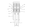
そして、図11〜図13に示すように電気機器(電力変換装置)cには端子台装置dが組み入れられていて、その端子台装置dは、絶縁体で一体成型された台座部eに、左から順に負極線接続部、正極線接続部、及び複数の交流線接続部(系統接続用の3つの端子台と自立運転時の交流出力用の3つの端子台)が構成されている。図12は前記端子台装置dにおける負極線接続部g、正極線接続部fを示しており、直流入力の正極入力部hが繋がる正極線接続部fには導電板jを配して、これに直流供給側からの正極線lに取り付けたリング状のターミナル端子nがネジ止めされ、直流入力の負極入力部iが繋がる負極線接続部gには導電板kを配して、これに直流供給側からの負極線mに取り付けたリング状のターミナル端子oがネジ止めされていた。また、前記複数の交流線接続部に接続されるターミナル端子にも全て同じ形状のものが使用され、ターミナル端子の形状が同じであることから、特に正極線接続部と負極線接続部とを逆接続した場合に不具合が生じるものであった。 As shown in FIGS. 11 to 13, a terminal block device d is incorporated in the electric device (power conversion device) c, and the terminal block device d is attached to a pedestal portion e integrally formed of an insulator, In order from the left, a negative electrode line connection part, a positive electrode line connection part, and a plurality of AC line connection parts (three terminal blocks for system connection and three terminal blocks for AC output during independent operation) are configured. FIG. 12 shows a negative electrode line connection part g and a positive electrode line connection part f in the terminal block device d. A conductive plate j is arranged on the positive electrode line connection part f connected to the positive electrode input part h of the DC input. A ring-shaped terminal terminal n attached to a positive electrode wire l from the DC supply side is screwed, and a conductive plate k is arranged at a negative electrode wire connection portion g to which a negative input portion i of DC input is connected. The ring-shaped terminal terminal o attached to the negative electrode wire m from the supply side was screwed. In addition, terminal terminals connected to the plurality of AC line connecting parts are all of the same shape, and the terminal terminals have the same shape. Therefore, the positive line connecting part and the negative line connecting part are particularly reversed. When connected, there was a problem.
このような逆接続を防ぐ工夫としては、特許文献1に示されているように蓄電池においてその一方の蓄電池端子自体を凹部を有する形状にするとともに、他方蓄電池端子自体を凸部を有する形状にし、さらに一方の引出線に取り付けた引出線端子自体に前記凹部と嵌合する凸片を設け、他方の引出線に取り付けた引出線端子自体に前記凸部と嵌合する凹切欠部を設けた工夫が提案されており、一方の蓄電池端子に他方の引出線を対応させかけたり、他方の蓄電池端子に一方の引出線を対応させかけた場合に、蓄電池端子と引出線端子とが嵌まり合わないようにしたものがあった。
As a device for preventing such reverse connection, as shown in
例えば、太陽電池で発電される直流電力を交流電力に変換する電力変換装置では、電力ケーブルを介して供給される直流電力を夫々端子台装置の正極線接続部と負極線接続部に接続する作業を行なっている。そして一般的にこの電力ケーブルの接続作業には家屋それぞれの形状によって異なる作業が必要になる。 For example, in a power conversion device that converts DC power generated by a solar cell into AC power, work for connecting DC power supplied via a power cable to the positive line connecting portion and the negative line connecting portion of the terminal block device, respectively. Is doing. In general, this power cable connection work requires different work depending on the shape of each house.
しかしながら、この電力ケーブルは正極用と負極用との二本の電線を対として用いる必要があり、両者に被覆の色に違いがあり、二本の電線のどちらの色にも接続先の極性を参照する対応があるものの、配線工事において限定的に定めているものではない。勿論、配線工事の際に二本の電線の内の一方の色の側を正極線用とし他方の色の側を負極線用と定めて取り扱うようになるが、端子台に接続する際に、この電線には正極・負極かかわらずに同じ形状のターミナル端子がかしめ固定されるため、電線の色を見落とした際には正極線と負極線とを端子台の正極線接続部と負極線接続部とに逆接続することがあった。 However, this power cable requires the use of two wires for the positive and negative electrodes as a pair, and there is a difference in the color of the coating on both of them. Although there is a correspondence to refer to, it is not limited in the wiring work. Of course, during wiring work, one color side of the two wires will be handled for the positive line and the other color side will be handled for the negative line, but when connecting to the terminal block, Because the terminal terminal of the same shape is caulked and fixed to this electric wire regardless of the positive and negative electrodes, if you overlook the color of the electric wire, connect the positive and negative wires to the positive and negative wire connections on the terminal block. And there was a reverse connection.
また、電力変換装置では直流電力が供給される端子台と交流電力が出力される端子台とが並置または単一の端子台として一体に構成されている場合が多く、さらにすべて同じ形状のターミナル端子が用いられている場合が多い。交流電力の出力には直流電力のような極性がなく電線の色分けは意味を有しておらず、直流電力、交流電力の配線が近接していることにより一層直流電力の逆接続を招き易くなっている。 Also, in power converters, a terminal block to which DC power is supplied and a terminal block to which AC power is output are often juxtaposed or integrally formed as a single terminal block. Is often used. The output of AC power is not as polar as DC power and the color coding of the wires has no meaning, and the close connection of the DC power and AC power wiring makes it easier to reverse connect DC power. ing.
この対策として上記特許文献1に示されている如く、例えば図12の例を基にして説明すれば、正極線接続部fの導電板jのターミナル端子nを受ける部分自体の形状を凹部を有する形状とし、他方の負極線接続部gの導電板kのターミナル端子oを受ける部分自体の形状を凸部を有する形状とし、さらに正極線接続部fに対応のターミナル端子nにあっては、前記凹部に嵌まる凸片のある形状とし、負極線接続部gに対応のターミナル端子oにあっては、前記凸部が嵌まる凹欠部のある形状とすることが考えられる。
As a countermeasure against this, as described in
しかし、正極線接続部と負極線接続部とのそれぞれに配される導電板は、ターミナル端子のネジ止めに際しても変形することのないように厚みのある導電金属板からなるものであるため、上述したように板厚み方向で凹んでなる凹部や板厚み方向に盛り上がってなる凸部を形成するとコスト高になるという問題があり、導電板の小型化を図る場合での前記凹部、凸部の形成自体が困難なものとなる。このため、現状において導電板それぞれのターミナル端子を受ける上面部分は平坦であり、ターミナル端子も同一形状としており、誤接続の可能性を無くすことが難しかった。 However, since the conductive plate disposed in each of the positive electrode line connecting portion and the negative electrode line connecting portion is made of a thick conductive metal plate so as not to be deformed even when the terminal terminal is screwed, As described above, there is a problem that forming a concave portion that is recessed in the thickness direction of the plate or a convex portion that is raised in the thickness direction of the plate increases the cost, and the formation of the concave portion and the convex portion in the case of reducing the size of the conductive plate. It becomes difficult. For this reason, the upper surface part which receives the terminal terminal of each electrically-conductive board is flat now, and the terminal terminal is also made into the same shape, It was difficult to eliminate the possibility of an incorrect connection.
そこで本発明は上記事情に鑑み、端子台装置の正極線接続部と負極線接続部とに繋ぐ正極線と負極線とのターミナル端子の形状が互いに異なるようにし、異なった極性側の接続部にターミナル端子が合わないようにする端子台を提供することを目的とする。 Therefore, in view of the above circumstances, the present invention is such that the terminal terminals of the positive electrode line and the negative electrode line connected to the positive electrode line connection part and the negative electrode line connection part of the terminal block device are different from each other, and the different polarity side connection parts are used. An object of the present invention is to provide a terminal block that prevents terminal terminals from being fitted.
(請求項1の発明)
本発明は上記課題を考慮してなされたもので、直流電力の正極側が接続されるリング状の正極用ターミナル端子がネジ止めされる正極線接続部と前記直流電力の負極側が接続されるリング状の負極用ターミナル端子がネジ止めされる負極線接続部とを有してなる端子台装置において、
前記正極線接続部と前記負極線接続部とを並べて一体に構成し、前記正極用ターミナル端子及び前記負極用ターミナル端子の少なくともいずれか一方のターミナル端子が他方のターミナル端子に対応する前記正極線接続部もしくは前記負極線接続部のいずれかにネジ止めをする際に不具合を生じさせる障害部を有することを特徴とする端子台装置を提供して、上記課題を解消するものである。
(Invention of Claim 1)
The present invention has been made in consideration of the above problems, and is a ring-shaped connection in which a positive electrode line connection portion to which a ring-shaped positive terminal terminal connected to a positive electrode side of DC power is screwed and a negative electrode side of the DC power is connected. In the terminal block device having a negative electrode wire connection portion to which the negative electrode terminal is screwed,
The positive electrode line connection part and the negative electrode line connection part are arranged side by side, and the positive electrode terminal connection is such that at least one of the positive terminal terminal and the negative terminal terminal corresponds to the other terminal terminal. In order to solve the above-mentioned problems, there is provided a terminal block device having an obstacle portion that causes a problem when screwing either of the electrode portion or the negative electrode line connecting portion.
(請求項2の発明)
また、本発明の端子台装置にあっては、前記障害部は、前記正極用ターミナル端子及び前記負極用ターミナル端子の他方のターミナル端子の外形異形部分に嵌るものとすることが良好である。
(Invention of Claim 2)
In the terminal block device of the present invention, it is preferable that the obstruction part fits into a deformed portion of the other terminal terminal of the positive terminal terminal and the negative terminal terminal.
(請求項3の発明)
また、本発明の端子台装置にあっては、前記正極線接続部及び前記負極線接続部はそれぞれ絶縁体である台座部の上に導電板を重ねてなると共に、前記障害部は台座部の一部分を突出させた凸部であることが良好である。
(Invention of Claim 3)
In the terminal block device of the present invention, the positive electrode line connecting portion and the negative electrode line connecting portion are each formed by overlapping a conductive plate on a pedestal portion that is an insulator, and the obstacle portion is a pedestal portion. It is good that it is the convex part which made one part protrude.
(請求項4の発明)
また、本発明の端子台装置にあっては、前記導電板は、障害部を補強する立片を有することが良好である。
(Invention of Claim 4)
In the terminal block device of the present invention, it is preferable that the conductive plate has a standing piece that reinforces the obstacle.
(請求項5の発明)
また、本発明の端子台装置にあっては、前記正極線接続部に接続される前記正極用のターミナル端子は前記正極線接続部を示す表示を有し、前記負極線接続部に接続される前記負極用のターミナル端子は前記負極線接続部を示す表示を有することが良好である。
(Invention of Claim 5)
In the terminal block device of the present invention, the positive terminal connected to the positive line connecting portion has a display indicating the positive line connecting portion and is connected to the negative line connecting portion. It is favorable that the terminal terminal for the negative electrode has a display indicating the negative electrode line connecting portion.
(請求項6の発明)
また、請求項6の電気機器は、再生可能エネルギーから得られる直流電力を正極の直流電力が供給されるリング状の正極用ターミナル端子がネジ止めされる正極線接続部と負極の直流電力が供給されるリング状の負極用ターミナル端子がネジ止めされる負極線接続部とを有してなる端子台装置を介して入力する当該端子台装置を備える電気機器において、
前記端子台装置から入力した前記直流電力を交流電力に変換して系統へ出力する複数の交流線接続部を有し、前記負極線接続部、前記正極線接続部、及び前記複数の交流線接続部を順に並べて一体に構成し、前記正極用ターミナル端子及び前記負極用ターミナル端子の少なくともいずれか一方のターミナル端子が他方のターミナル端子に対応する前記正極線接続部もしくは前記負極線接続部のいずれかにネジ止めをする際に不具合を生じさせる障害部を有する端子台装置を備えることを特徴とする電気機器であり、この電気機器を提供して上記課題を解消するものである。
(Invention of Claim 6)
According to another aspect of the electrical device of the present invention, the DC power obtained from the renewable energy is supplied with the positive line connecting portion to which the ring-shaped positive terminal terminal to which the positive DC power is supplied is screwed and the negative DC power. In an electrical apparatus comprising the terminal block device that is input via a terminal block device having a negative electrode wire connection portion to which a ring-shaped negative electrode terminal terminal is screwed,
It has a plurality of AC line connection parts that convert the DC power input from the terminal block device into AC power and output it to the system, the negative line connection part, the positive line connection part, and the plurality of AC line connections Are arranged in order and integrated, and at least one of the positive terminal terminal and the negative terminal terminal corresponds to the other terminal terminal, either the positive line connecting part or the negative line connecting part. It is an electrical device comprising a terminal block device having an obstruction that causes a problem when screwing to the device, and this electrical device is provided to solve the above problems.
(請求項7の発明)
また、本発明の電気機器にあっては、前記障害部は、前記正極用ターミナル端子及び前記負極用ターミナル端子の他方のターミナル端子の外形異形部分に嵌る請求項6に記載の端子台装置を備えることが良好である。
(Invention of Claim 7)
Moreover, in the electric equipment of this invention, the said obstruction part is equipped with the terminal block apparatus of
(請求項8の発明)
また、本発明の電気機器にあっては、前記障害部は、前記複数の交流線接続部に夫々接続され前記系統へつながるリング状のターミナル端子の前記正極接続部もしくは前記負極接続部への接続に際して不具合を生じさせる請求項6又は請求項7に記載の端子台装置を備えることが良好である。
(Invention of Claim 8)
Further, in the electrical device of the present invention, the obstacle is connected to the positive electrode connecting portion or the negative electrode connecting portion of each of the ring-shaped terminal terminals connected to the plurality of AC line connecting portions and connected to the system. In this case, it is preferable to provide the terminal block device according to
(請求項1の発明の効果)
請求項1の発明によれば、正極線接続部と負極線接続部に正極用ターミナル端子と前記負極用ターミナル端子とをその極性を不一致にして対応させようとした際、ネジ止めをすることへの不具合を生じさせる障害部の機能が働いた部分では接続部とターミナル端子とのネジ止めそのものができなくなり、作業者は誤接続であることを簡単に知ることができて、その誤接続を未然に防止することができるという優れた効果を奏するものである。
(Effect of the invention of claim 1)
According to the first aspect of the present invention, when the positive electrode terminal and the negative electrode terminal are made to correspond to the positive electrode terminal and the negative electrode connector with the polarities mismatched, the screws are fixed. In the part where the function of the faulty part that causes the malfunction occurs, it becomes impossible to screw the connection part and the terminal terminal itself, and the operator can easily know that it is a wrong connection, and the erroneous connection has not occurred. It has an excellent effect that it can be prevented.
(請求項2の発明の効果)
請求項2の発明によれば、障害部がターミナル端子の外形異形部分に嵌まるようにしているので、ターミナル端子を各接続部に対応させる際に、前記障害部の有無、位置、数などの確認とターミナル端子側の形状の確認とを行なうことで、極性が一致する対応付けであるか否かが簡単に判るようになる。また、障害部がターミナル端子の外形異形部分に嵌まるようにしているため、ターミナル端子自体の位置決めが頗る良好になるという優れた効果を奏する。
(Effect of the invention of claim 2)
According to the invention of claim 2, since the obstacle part fits into the outer shape deformed part of the terminal terminal, when the terminal terminal is made to correspond to each connection part, the presence / absence, position, number, etc. of the obstacle part are By confirming and confirming the shape of the terminal terminal side, it is possible to easily determine whether or not the correspondence matches the polarity. In addition, since the obstacle part is fitted in the externally shaped part of the terminal terminal, the terminal terminal itself is excellently positioned.
(請求項3の発明の効果)
請求項3の発明によれば、障害部は台座部の一部分を上方に向けて突出させた凸部であるので、その障害部の構造が極めて簡単で端子台装置の製造コストを引き上げないという優れた効果を奏する。
(Effect of the invention of claim 3)
According to the invention of claim 3, since the obstacle part is a convex part protruding a part of the pedestal part upward, the structure of the obstacle part is extremely simple and does not raise the manufacturing cost of the terminal block device. Has an effect.
(請求項4の発明の効果)
請求項4の発明によれば、障害部が立片にて支えられているのでその障害部自体の強度が向上し、極性不適合の状態でターミナル端子が接続部に配置されかけても障害部がそのターミナル端子に当接し続けて、誤接続をより確実に防止できるという優れた効果を奏する。
(Effect of the invention of claim 4)
According to the invention of
(請求項5の発明の効果)
請求項5の発明によれば、正極用、及び負極用のターミナル端子それぞれに設けられた表示を作業者が目視にて確認することで、そのターミナル端子を対応付ける接続部を簡単に把握でき、誤接続をより確実に防止できるという優れた効果を奏する。
(Effect of the invention of claim 5)
According to the invention of claim 5, the operator can visually grasp the display provided on each of the positive electrode terminal and the negative electrode terminal terminal so that the connecting portion to which the terminal terminal is associated can be easily grasped. There is an excellent effect that the connection can be more reliably prevented.
(請求項6の発明の効果)
請求項6の発明によれば、端子台装置に直流電力供給側のケーブルにおける正極線と負極線とを接続するに際し、極性を誤って接続しかけた場合には、端子台装置の一方の接続部では、誤った極性側の端子となっているターミナル端子を接続することができないようになり、作業者は誤接続であることを簡単に知ることができて、誤接続を未然に防止することができるという優れた効果を奏するものである。
(Effect of the invention of claim 6)
According to the sixth aspect of the present invention, when connecting the positive and negative electrodes in the cable on the DC power supply side to the terminal block device, if the polarity is wrongly connected, one connection portion of the terminal block device is connected. Then, it becomes impossible to connect the terminal terminal which is the terminal of the wrong polarity side, the operator can easily know that it is a wrong connection, and can prevent the wrong connection in advance. It has an excellent effect of being able to.
(請求項7の発明の効果)
請求項7の発明によれば、障害部がターミナル端子の外形異形部分に嵌まるようにしているので、ターミナル端子を各接続部に対応させる際に、前記障害部の有無、位置、数などの確認とターミナル端子側の形状の確認とを行なうことで、極性が一致する対応付けであるか否かが簡単に判るようになる。また、障害部がターミナル端子の外形異形部分に嵌まるようにしているため、ターミナル端子自体の位置決めが頗る良好になるという優れた効果を奏する。
(Effect of the invention of claim 7)
According to the invention of
(請求項8の発明の効果)
請求項8の発明によれば、複数の交流線接続部に夫々接続されて系統へつながるリング状のターミナル端子を、誤って正極線接続部や負極線接続部へ対応付けして誤接続することを確実に防止できるという優れた効果を奏するものである。
(Effect of the invention of claim 8)
According to the invention of
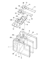
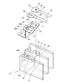
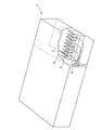
つぎに本発明を図1から図9に示す実施の形態に基づいて詳細に説明する。なお、上述した従来の例と構成が重複する部分は同符号を付してその説明を省略する。図1に示すように電力変換装置(電気機器)1は、主に直流電力を交流電力に変換する構成の部分Aと、直流側につながる正極線接続部9及び負極線接続部10、系統側へつながる交流接続部(交流用端子2つと中間端子との3つの端子)、及び自立運転時の交流接続部(交流用端子2つと接地用端子との3つの端子)が1列の直線状に配置されるように絶縁性の樹脂で一体に成形された端子台装置4のある部分Bとをケース内に組み入れられているものである。本発明は前記部分Bの端子台装置4に工夫が施されている。
Next, the present invention will be described in detail based on the embodiment shown in FIGS. In addition, the part which a structure overlaps with the conventional example mentioned above attaches | subjects the same code | symbol, and abbreviate | omits the description. As shown in FIG. 1, a power conversion device (electrical device) 1 is mainly composed of a part A configured to convert DC power into AC power, a positive
(第一の例)
接続箱b(図10参照)と電力変換装置1とをケーブル接続する際の電力変換装置1に組み入れられた上記端子台装置4にあっては、正極線接続部9と負極線接続部10とに対しケーブル8の正極線13と負極線14とが誤接続されないようにするための工夫が設けられていて、図2から図5はその第一の例を示している。この端子台装置4においては、直流電力入力側(直流接続側)の正極入力部6と正極線接続部9との内、正極線接続部9の方が高い位置になる階段状に成形されている。負極入力部7と負極線接続部10とにおいても同様の高さ関係がある。
(First example)
In the
図3に示すように、正極入力部6から正極線接続部9にかけては略Z字状に屈曲した導電板11を取り付けられ、負極入力部7から負極線接続部10にかけても同じように略Z字状に屈曲した導電板12を取り付けられており、台座部5の前記正極線接続部9(取付面19)には導電板11の上平板11aが位置し、前記負極線接続部10(取付面20)には導電板12の上平板12aが位置している。
As shown in FIG. 3, a
正極線接続部9と負極線接続部10とのそれぞれには、正極線13にかしめ固定したターミナル端子21と、負極線14にかしめ固定したターミナル端子22とのそれぞれをネジ止めできるように上平板11a、12aからその下位の取付面19、20にかけて、その取付面19、20の中央線上となるようにしてネジ孔16a、bが設けられている。また、前記上平板11aと上平板12aとが配置されている部分においては、正極線接続部9と負極線接続部10とには互いに異なる位置にして障害部23a、23b(突起、または凸部など)を台座部5の樹脂による成形の際に一体に成形されていて、図3に示されているように正極線接続部9に障害部23aがあり、負極線接続部10に障害部23bがある。
Each of the positive electrode
正極線接続部9の障害部23aに関して、取付面19では、正極入力部6側(段落ちされた側)の端部の両側に設けられており、取付面19の端部両側の部分を上方に向けて突設させた凸部によってその障害部23aが台座部5に対して一体に成されている。さらにこの対の障害部23aは両脇の壁にも一体となって成形されており、これによって障害部23aそれぞれは、ターミナル端子をネジ止めした際の押え付け力で段落ち側に倒れ込みしないように補強した構造としている。この対の障害部23aは取付面19の中央線位置に対して線対称となる位置にあり、形状も線対称としている。
With respect to the
負極線接続部10の障害部23bに関して、取付面20では、負極入力部7側(段落ちされた側)の端部の中央に設けられており、その中央の部分を上方に向けて突出させた凸部によって台座部5に一体にして形成されている。取付面20でのこの障害部23bは一つであって単独で突出しているものであるが、ターミナル端子をネジ止めした際の押え付け力を受けても段落ち側に折曲しないように後述の導電板で支持されて補強されているものである。この単独で起立する障害部23bは取付面20の中央線位置に対してその中央線上に位置し、単独の形状も線対称の形状としている。
With respect to the
また、上記障害部23a、23bの上端は、両接続部9、10に対して適正な極性側となっているターミナル端子が上方から乗せ置かれるときに上平板11a、12a側にスムーズに下りるようにするために面取りされた形状としている。
Further, the upper ends of the
図3に示すように、正極線接続部9に配置される導電板11の上平板11aには、正極線接続部9での対の障害部23aの位置を避けてその障害部23aを上方に通すことができるように切り欠きからなる回避部24aが設けられているとともに、負極線接続部10に配置される導電板12の上平板12aには、負極線接続部10の単独の障害部23bの位置を避けてその障害部23bを上方に通すことができるように開口からなる回避部24bが設けられている。なお、図3に示す分解した構成では台座部5の下部(接続器として複数の端子台構成部分の基部が繋がる箇所)は端子台装置4の説明を容易にするためにその図示を略した。
As shown in FIG. 3, the
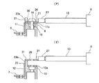
さらに上平板12bの開口からなる回避部24bにあっては、ターミナル端子を重ね合わせた際にそのターミナル端子と干渉しない位置、実施の例にあっては開口の回避部24bにおける屈曲部分側の辺に立片25が一体にして立ち上げられており、図5(イ)に示すように負極線接続部10において上平板12aを配置することで前記立片25が障害部23bの側面に対応位置して、この障害部23bがターミナル端子から押さえ付けられても倒れ込みしないように補強する。
Further, in the avoiding
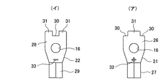
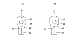
図4に示すように、一方、正極線13にかしめ固定されたターミナル端子21(図4(ア))と、負極線14にかしめ固定されたターミナル端子22(図4(イ))とにおいては、従来のターミナル端子と同じように上記両接続部9、10のネジ孔位置と応じた位置にネジ孔16を有した平板部26、28とかしめ部27、29とからなり、平板部26、28の外形形状が互いに異なっている。
On the other hand, as shown in FIG. 4, in the terminal terminal 21 (FIG. 4A) fixed to the
即ち、このターミナル端子21、22の平板部26、28の互いの外形形状の相違と上記障害部23a、23bとを利用して、作業者が誤接続を直ぐに判るようにすることを目的としているもので、正極線接続部9や負極線接続部10にその極性が相違する状態でターミナル端子21や22が配されかけた場合に、障害部23bにターミナル端子21が乗って、平板部26が上平板12aに重ねられないように(図5(イ)参照)、また、障害部23aにターミナル端子22が乗って、平板部28が上平板11aに重ねられないようにしている。一対の正極線接続部9と負極線接続部10に対して一対の正極線13と負極線14を繋ぐ場合の誤接続を防止するものであることから、一方でのネジ止め作業で誤接続が行なわれかけたことが作業員側に判断できればよいものであるが、この第一の例にあっては、ターミナル端子21、22のいずれでも誤接続が判断できるようにしている。
That is, an object is to make it possible for an operator to immediately recognize an erroneous connection by utilizing the difference in the external shape of the
図4に示すように正極線13に取り付けられるターミナル端子21の平板部26でのかしめ部27とは反対の端部両側(外端両側)には、切り欠きからなる外形異形部分30が設けられている。この切り欠きからなる対の外形異形部分30は、ターミナル端子21のネジ孔の位置を通る中心線を中心にして線対称となる位置であり、線対称となる切り欠き形状にしている。そして、正極線接続部9に、この正極線接続部9の極性と同じ極性となっている前記ターミナル端子21を配置する際には、正極線接続部9での上記対の障害部23aが切り欠きの外形異形部分30それぞれの位置に嵌まり込み、上平板11aにターミナル端子21の平板部26を重ね合わせることで、上平板11aのネジ孔16の位置と平板部26のネジ孔16の位置とを合わせることができて、ネジ止めできるようにしている(図5(ア)参照)。
As shown in FIG. 4, a deformed
同様に負極線14に取り付けられるターミナル端子22の平板部28でのかしめ部29とは反対の端部中央に切り欠きからなる一つの外形異形部分30が設けられ、ターミナル端子22のネジ孔の位置を通る中心線上に位置しており、前記一つの外形異形部分30自体の形状はネジ孔の位置を通る中心線に対して線対称としている。そして、負極線接続部10に、この負極線接続部10の極性と同じ極性となっている前記ターミナル端子22を配置する際には、負極線接続部10での上記一つの障害部23bが前記一つの外形異形部分30の位置に嵌まり込み、上平板12aにターミナル端子22の平板部28を重ね合わせることで、上平板12aのネジ孔16の位置と平板部28のネジ孔16の位置とを合わせることができ、ネジ止めできるようにしている。
Similarly, one outer shape-deformed
ターミナル端子21とターミナル端子22との両者の外形形状を比較して明らかなように、互いに対応する部分での外形異形部分30の有無によってターミナル端子21とターミナル端子22との両者の外形形状が異なっている。そして、一方のターミナル端子である正極線13に取り付けたターミナル端子21の平板部26のかしめ部27とは反対の中央部分、即ち、前記ターミナル端子21の対の外形異形部分30の間であって、他方のターミナル端子である負極線14に取り付けたターミナル端子22の切り欠きからなる外形異形部分30に対応する部分は、図示から明らかなように切り欠き非存在の平板31として形成されてなるものである。
As apparent from the comparison of the external shapes of the
このように正極線13に取り付けられているターミナル端子21の平板部26の外端中央は、切り欠きとはせずに平板31とした部分がある。そして、図5(イ)に示されているように、正極のターミナル端子21を負極線接続部10に対応させようとする際には、その負極線接続部10での上記障害部23bに正極のターミナル端子21の平板31が乗るようにして当接することとなる。よって、負極線接続部10の導電板12の上平板12aに正極のターミナル端子21の平板部26が重ならず、誤った接続でのネジ止め作業を防止する。また、前記障害部23bも導電板12での立片25で支えられているので倒れ込みせず、これによっても正極のターミナル端子21の平板部26の誤った重ね合わせをより一層確実に防止する。
In this way, the center of the outer end of the
同様に、他方のターミナル端子である負極線14に取り付けたターミナル端子22での平板31の位置についても説明する。負極のターミナル端子22の平板部28のかしめ部29とは反対の外端両側、即ち、平板部28の外端中央の切り欠きからなる外形異形部分30の両側であって、上記一方のターミナル端子である正極線13に取り付けたターミナル端子21の上記対の外形異形部分30に対応する部分それぞれを、切り欠きとはしていない平板31として設けている。前記対の平板31は、正極のターミナル端子21の対の切り欠きからなる外形異形部分30に対応する位置であり、平板部28の中心線を中心として線対称となる位置に設けられている。
Similarly, the position of the
そして、負極線14に取り付けられているターミナル端子22では、平板部28の外端両側に平板31があるので、負極のターミナル端子22を、例えば正極線接続部9に対応させて接続しようとする際には、正極線接続部9での対の障害部23aにこの負極のターミナル端子22の平板31が乗るようにして当接することとなり、正極線接続部9の導電板11の上平板11aに負極のターミナル端子22の平板部28が重ならず、誤った接続でのネジ止め作業を防止する。
In the
正極線接続部9の対の障害部23aに対応して平板部26に二つの外形異形部分30(切り欠き)を設けたターミナル端子21と、負極線接続部10の一つの障害部23bに対応して平板部28に一つの外形異形部分30(切り欠き)を設けたターミナル端子22とでは、互いに外形異形部分30の位置、個数を異ならせて上記平板31を形成している。このように正極のターミナル端子21と負極のターミナル端子22とは対応する同一箇所での切り欠き(外形異形部分30)の有無によって外形形状を相違させているだけであるため、製造コストを上昇させず、そして誤接続も簡単に判るものとなっている。
Corresponding to the
(第二の例)
図6から図8は第二の例を示している。上記第一の例では正極のターミナル端子21と負極のターミナル端子22とのいずれにも切り欠きからなる外形異形部分30を設けているが、この第二の例は一方のターミナル端子にのみ切り欠きからなる外形異形部分を設けた構成である。図示しているように、本端子台装置4の正極線接続部9と負極線接続部10ではそれぞれ導電板11、12の上平板11a、12aの屈曲側中央に開口の回避部24a、24bが設けられている。前記上平板11aと12bとは同一形状であり、導電板11と12とを同一形状としている。そして、正極線接続部9では前記上平板11aを通る障害部は設けられておらず、負極線接続部10でのみ前記上平板12aの回避部24bを通して上方に向けて突出する障害部23bが設けられている。
(Second example)
6 to 8 show a second example. In the first example, the positive terminal terminal 21 and the negative terminal terminal 22 are each provided with an externally
図8(ア)に示すように上記正極線接続部9に対応する正極線13に取り付けたターミナル端子21は、平板部26のかしめ部27とは反対の外端を円弧形状にして外端の中央を平板31としており、前記平板部26は切り欠き(外形異形部分)を有しない外形形状としている。この正極のターミナル端子21を正極線接続部9に配した状態では、上平板11の回避部24aの一部分に平板部26の外端部分がかかるように位置し、この状態でネジ止めできるようにしている(図6参照)。また、正極のターミナル端子21を負極線接続部10に配しようとした際には、負極線接続部10の一つの障害部23bにターミナル端子21の平板31が当接することとなり、誤接続の状態では正極のターミナル端子21をネジ止めできないようになる。
As shown in FIG. 8A, the
また、図8(イ)に示すように負極線接続部10に対応する負極線14に取り付けたターミナル端子22は、平板部28のかしめ部29とは反対の外端中央(中心線上の位置)にして切り欠きからなる外形異形部分30が設けられており、負極線接続部10にターミナル端子22を配した状態では障害部23bが前記外形異形部分30に嵌まって、適正にネジ止めできるようにしている(図6参照)。また、この負極のターミナル端子22を極性の異なる正極線接続部9に対応させた場合、上述したように正極線接続部9に障害部が設けられていないので、誤接続の状態で接続することとなる。しかしながら、残りの正極のターミナル端子21を負極線接続部10側に配しなければならないこととなり、上述したように正極のターミナル端子21が負極線接続部10に、構造上、接続できないので、やはり誤接続であることが容易に判断できるものとなっている。
Further, as shown in FIG. 8 (a), the
上述した第一の例においては、正極のターミナル端子21と負極のターミナル端子22との平板部26、28それぞれの外端に切り欠きからなる外形異形部分30を設けているが、外形異形部分30、即ち切り欠きを設ける領域は外端に限定されるものではない。例えば図9に示すようにターミナル端子21、22の平板部26、28における両側端に外形異形部分30を設けるようにしてもよく、正極のターミナル端子21の平板部26の両側の外形異形部分30と負極のターミナル端子22の平板部28の両側の外形異形部分30との位置を異ならせて、それぞれ対応する箇所に平板31を形成するようにしてもよい。勿論、この場合のターミナル端子21、22をネジ止めする正極線接続部9、負極線接続部10の障害部23a、23bの位置も、接続部と極性が同じターミナル端子の前記外形異形部分の位置に対応するようにする。このように正極のターミナル端子21と負極のターミナル端子22との平板部26、28それぞれの平板部26、28に設ける外形異形部分30の個数を同じとしても、その位置を互いに異ならせることで誤接続を簡単に防止できる。
In the first example described above, the outer shape deformed
第一の例及び第二の例において、図4と図8に示されているように正極のターミナル端子21の平板部26のかしめ部27の近傍には、正極線接続部9を示す+の表示32が設けられているとともに、負極のターミナル端子22の平板部28のかしめ部29の近傍には、負極線接続部10を示す−の表示33が設けられており、接続をする作業者が前記表示32、33を目視確認することでも、ターミナル端子21、22をその極性が不適合とならないように接続すべき箇所が正極線接続部9と負極線接続部10のいずれであるかを判断し易くしている。これによって誤接続を防止する効果がより高められている。
In the first example and the second example, as shown in FIGS. 4 and 8, a positive
上述したように本端子台装置4にあっては、直流側につながる並設された正極線接続部9と負極線接続部10との他にこれに一列にして直線状に並ぶように、系統側へつながる交流接続部、及び自立運転時の交流接続部が配置されているものである。
As described above, in the
1…電気機器
4…端子台装置
5…台座部
6…正極入力部
7…負極入力部
8…ケーブル
9…正極線接続部
10…負極線接続部
11…正極側の導電板
11a…上平板
12…負極側の導電板
12a…上平板
13…正極線
14…負極線
16…ネジ孔
21…正極線のターミナル端子
22…負極線のターミナル端子
23a、23b…障害部
24a、24b…回避部
25…立片
26…ターミナル端子の平板部
27…ターミナル端子のかしめ部
28…ターミナル端子の平板部
29…ターミナル端子のかしめ部
30…外形異形部分
31…平板
A…変換機器として構成されている部分
B…接続部として構成されている部分
DESCRIPTION OF
Claims (8)
前記正極線接続部と前記負極線接続部とを並べて一体に構成し、前記正極用ターミナル端子及び前記負極用ターミナル端子の少なくともいずれか一方のターミナル端子が他方のターミナル端子に対応する前記正極線接続部もしくは前記負極線接続部のいずれかにネジ止めをする際に不具合を生じさせる障害部を有することを特徴とする端子台装置。 A positive electrode wire connection portion to which a ring-shaped positive electrode terminal terminal to which a positive electrode side of DC power is connected is screwed, and a negative electrode wire connection portion to which a ring-shaped negative electrode terminal terminal to which the negative electrode side of DC power is connected is screwed In a terminal block device comprising:
The positive electrode line connection part and the negative electrode line connection part are arranged side by side, and the positive electrode terminal connection is such that at least one of the positive terminal terminal and the negative terminal terminal corresponds to the other terminal terminal. A terminal block device comprising an obstacle portion that causes a problem when screwing to either the negative electrode portion or the negative electrode wire connecting portion.
前記端子台装置から入力した前記直流電力を交流電力に変換して系統へ出力する複数の交流線接続部を有し、前記負極線接続部、前記正極線接続部、及び前記複数の交流線接続部を順に並べて一体に構成し、前記正極用ターミナル端子及び前記負極用ターミナル端子の少なくともいずれか一方のターミナル端子が他方のターミナル端子に対応する前記正極線接続部もしくは前記負極線接続部のいずれかにネジ止めをする際に不具合を生じさせる障害部を有する端子台装置を備えることを特徴とする電気機器。 DC power obtained from renewable energy is connected to a positive electrode wire connection part to which a ring-shaped positive electrode terminal terminal supplied with positive DC power is screwed and a ring-shaped negative electrode terminal terminal supplied with negative DC power In an electrical device comprising the terminal block device that inputs via a terminal block device having a negative electrode line connection portion to be screwed,
It has a plurality of AC line connection parts that convert the DC power input from the terminal block device into AC power and output it to the system, the negative line connection part, the positive line connection part, and the plurality of AC line connections Are arranged in order and integrated, and at least one of the positive terminal terminal and the negative terminal terminal corresponds to the other terminal terminal, either the positive line connecting part or the negative line connecting part. An electric device comprising a terminal block device having an obstructing part that causes a problem when screwing to a cable.
Priority Applications (1)
| Application Number | Priority Date | Filing Date | Title |
|---|---|---|---|
| JP2013009995A JP2014143045A (en) | 2013-01-23 | 2013-01-23 | Terminal block device and electrical appliance with terminal block device |
Applications Claiming Priority (1)
| Application Number | Priority Date | Filing Date | Title |
|---|---|---|---|
| JP2013009995A JP2014143045A (en) | 2013-01-23 | 2013-01-23 | Terminal block device and electrical appliance with terminal block device |
Publications (1)
| Publication Number | Publication Date |
|---|---|
| JP2014143045A true JP2014143045A (en) | 2014-08-07 |
Family
ID=51424186
Family Applications (1)
| Application Number | Title | Priority Date | Filing Date |
|---|---|---|---|
| JP2013009995A Pending JP2014143045A (en) | 2013-01-23 | 2013-01-23 | Terminal block device and electrical appliance with terminal block device |
Country Status (1)
| Country | Link |
|---|---|
| JP (1) | JP2014143045A (en) |
Cited By (1)
| Publication number | Priority date | Publication date | Assignee | Title |
|---|---|---|---|---|
| JP2024139343A (en) * | 2023-03-27 | 2024-10-09 | 本田技研工業株式会社 | Terminal Blocks |
Citations (5)
| Publication number | Priority date | Publication date | Assignee | Title |
|---|---|---|---|---|
| JPS5838974U (en) * | 1981-09-09 | 1983-03-14 | 株式会社ユアサコーポレーション | Storage battery terminal device |
| JPH08222297A (en) * | 1995-02-13 | 1996-08-30 | Sumitomo Wiring Syst Ltd | Installing structure of terminal metal fitting |
| JP2000058156A (en) * | 1998-08-03 | 2000-02-25 | Fuji Electric Co Ltd | Semiconductor device package |
| JP2004152683A (en) * | 2002-10-31 | 2004-05-27 | Sumitomo Wiring Syst Ltd | Combined terminal |
| JP2011234440A (en) * | 2010-04-23 | 2011-11-17 | Panasonic Electric Works Denro Co Ltd | Distribution board |
-
2013
- 2013-01-23 JP JP2013009995A patent/JP2014143045A/en active Pending
Patent Citations (5)
| Publication number | Priority date | Publication date | Assignee | Title |
|---|---|---|---|---|
| JPS5838974U (en) * | 1981-09-09 | 1983-03-14 | 株式会社ユアサコーポレーション | Storage battery terminal device |
| JPH08222297A (en) * | 1995-02-13 | 1996-08-30 | Sumitomo Wiring Syst Ltd | Installing structure of terminal metal fitting |
| JP2000058156A (en) * | 1998-08-03 | 2000-02-25 | Fuji Electric Co Ltd | Semiconductor device package |
| JP2004152683A (en) * | 2002-10-31 | 2004-05-27 | Sumitomo Wiring Syst Ltd | Combined terminal |
| JP2011234440A (en) * | 2010-04-23 | 2011-11-17 | Panasonic Electric Works Denro Co Ltd | Distribution board |
Cited By (2)
| Publication number | Priority date | Publication date | Assignee | Title |
|---|---|---|---|---|
| JP2024139343A (en) * | 2023-03-27 | 2024-10-09 | 本田技研工業株式会社 | Terminal Blocks |
| JP7618719B2 (en) | 2023-03-27 | 2025-01-21 | 本田技研工業株式会社 | Terminal Blocks |
Similar Documents
| Publication | Publication Date | Title |
|---|---|---|
| JP5817535B2 (en) | Wiring module | |
| EP2725663B1 (en) | Connector | |
| EP2953181B1 (en) | Wiring module | |
| JP5590079B2 (en) | Battery wiring module | |
| JP5757252B2 (en) | Wiring module | |
| US8678842B2 (en) | Terminal connection structure | |
| JP2017208303A (en) | Plug connector and power circuit breaker | |
| WO2015170642A1 (en) | Power storage module | |
| WO2016047477A1 (en) | Wiring module | |
| CN108321740A (en) | High-tension distribution box and electric vehicle | |
| JP2015153554A (en) | wiring module | |
| JP2014143045A (en) | Terminal block device and electrical appliance with terminal block device | |
| JP2016162609A (en) | Electricity storage pack | |
| JP6264217B2 (en) | Wiring module | |
| JP5974918B2 (en) | Wiring module | |
| JP6033100B2 (en) | Terminal block device and electrical equipment including the terminal block device | |
| US20120094552A1 (en) | Electric terminal for leading a conductor through a wall | |
| JP6100537B2 (en) | Terminal block device and electric device including terminal block device | |
| CN102856690B (en) | A loop connection device and automobile wiring harness | |
| CN221507983U (en) | Switchgear | |
| JP6160543B2 (en) | Wiring module | |
| CN102299433A (en) | medical assembled connector | |
| JP2017050165A (en) | socket | |
| KR200375777Y1 (en) | A battery socket | |
| JP5780181B2 (en) | Connector device |
Legal Events
| Date | Code | Title | Description |
|---|---|---|---|
| A621 | Written request for application examination |
Free format text: JAPANESE INTERMEDIATE CODE: A621 Effective date: 20160112 |
|
| A977 | Report on retrieval |
Free format text: JAPANESE INTERMEDIATE CODE: A971007 Effective date: 20160909 |
|
| A131 | Notification of reasons for refusal |
Free format text: JAPANESE INTERMEDIATE CODE: A131 Effective date: 20160920 |
|
| A521 | Written amendment |
Free format text: JAPANESE INTERMEDIATE CODE: A523 Effective date: 20161117 |
|
| A131 | Notification of reasons for refusal |
Free format text: JAPANESE INTERMEDIATE CODE: A131 Effective date: 20170314 |
|
| A02 | Decision of refusal |
Free format text: JAPANESE INTERMEDIATE CODE: A02 Effective date: 20171003 |