JP2014146579A - 端子用取付けベース、端子、およびオーディオ機器 - Google Patents
端子用取付けベース、端子、およびオーディオ機器 Download PDFInfo
- Publication number
- JP2014146579A JP2014146579A JP2013016085A JP2013016085A JP2014146579A JP 2014146579 A JP2014146579 A JP 2014146579A JP 2013016085 A JP2013016085 A JP 2013016085A JP 2013016085 A JP2013016085 A JP 2013016085A JP 2014146579 A JP2014146579 A JP 2014146579A
- Authority
- JP
- Japan
- Prior art keywords
- terminal
- hole
- connector
- screw
- mounting base
- Prior art date
- Legal status (The legal status is an assumption and is not a legal conclusion. Google has not performed a legal analysis and makes no representation as to the accuracy of the status listed.)
- Granted
Links
Images



Classifications
-
- H—ELECTRICITY
- H01—ELECTRIC ELEMENTS
- H01R—ELECTRICALLY-CONDUCTIVE CONNECTIONS; STRUCTURAL ASSOCIATIONS OF A PLURALITY OF MUTUALLY-INSULATED ELECTRICAL CONNECTING ELEMENTS; COUPLING DEVICES; CURRENT COLLECTORS
- H01R4/00—Electrically-conductive connections between two or more conductive members in direct contact, i.e. touching one another; Means for effecting or maintaining such contact; Electrically-conductive connections having two or more spaced connecting locations for conductors and using contact members penetrating insulation
- H01R4/28—Clamped connections, spring connections
- H01R4/38—Clamped connections, spring connections utilising a clamping member acted on by screw or nut
-
- H—ELECTRICITY
- H01—ELECTRIC ELEMENTS
- H01R—ELECTRICALLY-CONDUCTIVE CONNECTIONS; STRUCTURAL ASSOCIATIONS OF A PLURALITY OF MUTUALLY-INSULATED ELECTRICAL CONNECTING ELEMENTS; COUPLING DEVICES; CURRENT COLLECTORS
- H01R24/00—Two-part coupling devices, or either of their cooperating parts, characterised by their overall structure
- H01R24/38—Two-part coupling devices, or either of their cooperating parts, characterised by their overall structure having concentrically or coaxially arranged contacts
- H01R24/40—Two-part coupling devices, or either of their cooperating parts, characterised by their overall structure having concentrically or coaxially arranged contacts specially adapted for high frequency
- H01R24/52—Two-part coupling devices, or either of their cooperating parts, characterised by their overall structure having concentrically or coaxially arranged contacts specially adapted for high frequency mounted in or to a panel or structure
- H01R24/525—Outlets
-
- H—ELECTRICITY
- H01—ELECTRIC ELEMENTS
- H01R—ELECTRICALLY-CONDUCTIVE CONNECTIONS; STRUCTURAL ASSOCIATIONS OF A PLURALITY OF MUTUALLY-INSULATED ELECTRICAL CONNECTING ELEMENTS; COUPLING DEVICES; CURRENT COLLECTORS
- H01R27/00—Coupling parts adapted for co-operation with two or more dissimilar counterparts
-
- H—ELECTRICITY
- H01—ELECTRIC ELEMENTS
- H01R—ELECTRICALLY-CONDUCTIVE CONNECTIONS; STRUCTURAL ASSOCIATIONS OF A PLURALITY OF MUTUALLY-INSULATED ELECTRICAL CONNECTING ELEMENTS; COUPLING DEVICES; CURRENT COLLECTORS
- H01R4/00—Electrically-conductive connections between two or more conductive members in direct contact, i.e. touching one another; Means for effecting or maintaining such contact; Electrically-conductive connections having two or more spaced connecting locations for conductors and using contact members penetrating insulation
- H01R4/28—Clamped connections, spring connections
- H01R4/48—Clamped connections, spring connections utilising a spring, clip, or other resilient member
-
- H—ELECTRICITY
- H01—ELECTRIC ELEMENTS
- H01R—ELECTRICALLY-CONDUCTIVE CONNECTIONS; STRUCTURAL ASSOCIATIONS OF A PLURALITY OF MUTUALLY-INSULATED ELECTRICAL CONNECTING ELEMENTS; COUPLING DEVICES; CURRENT COLLECTORS
- H01R2103/00—Two poles
-
- H—ELECTRICITY
- H01—ELECTRIC ELEMENTS
- H01R—ELECTRICALLY-CONDUCTIVE CONNECTIONS; STRUCTURAL ASSOCIATIONS OF A PLURALITY OF MUTUALLY-INSULATED ELECTRICAL CONNECTING ELEMENTS; COUPLING DEVICES; CURRENT COLLECTORS
- H01R9/00—Structural associations of a plurality of mutually-insulated electrical connecting elements, e.g. terminal strips or terminal blocks; Terminals or binding posts mounted upon a base or in a case; Bases therefor
- H01R9/03—Connectors arranged to contact a plurality of the conductors of a multiconductor cable, e.g. tapping connections
- H01R9/05—Connectors arranged to contact a plurality of the conductors of a multiconductor cable, e.g. tapping connections for coaxial cables
- H01R9/0521—Connection to outer conductor by action of a nut
-
- H—ELECTRICITY
- H01—ELECTRIC ELEMENTS
- H01R—ELECTRICALLY-CONDUCTIVE CONNECTIONS; STRUCTURAL ASSOCIATIONS OF A PLURALITY OF MUTUALLY-INSULATED ELECTRICAL CONNECTING ELEMENTS; COUPLING DEVICES; CURRENT COLLECTORS
- H01R9/00—Structural associations of a plurality of mutually-insulated electrical connecting elements, e.g. terminal strips or terminal blocks; Terminals or binding posts mounted upon a base or in a case; Bases therefor
- H01R9/03—Connectors arranged to contact a plurality of the conductors of a multiconductor cable, e.g. tapping connections
- H01R9/05—Connectors arranged to contact a plurality of the conductors of a multiconductor cable, e.g. tapping connections for coaxial cables
- H01R9/0524—Connection to outer conductor by action of a clamping member, e.g. screw fastening means
Landscapes
- Coupling Device And Connection With Printed Circuit (AREA)
- Connections By Means Of Piercing Elements, Nuts, Or Screws (AREA)
- Connections Arranged To Contact A Plurality Of Conductors (AREA)
Abstract
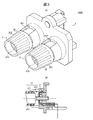
【解決手段】スピーカ端子の取付けベース1は、プッシュ及びスクリューの両タイプのコネクタを取付け可能である。取付けベース1には、貫通穴1211付き端子部121が固定されるコネクタ固定用ボス部111が形成され、コネクタ固定用ボス部111には、端子部121の貫通穴1211につながる貫通穴1112が形成されている。貫通穴1112は大径部11121と小径部11122とを有する。スクリュータイプのコネクタを取り付ける場合、コネクタの雄ネジ部を軸方向に送るナットが端子板12の取付け前に大径部11121に回転不能に収容される。プッシュタイプのコネクタを取り付けると、小径部11122の内周に形成された平坦面11123がコネクタの平坦面と面接触して、コネクタの回転を阻止する。
【選択図】図1
Description
外部から挿入されたケーブルと端子部材とを電気的に接続するための2つのコネクタが取り付けられる端子用取付けベースであって、
前記2つのコネクタ各々に対応付けられて設けられた2つの前記端子部材と、
前記端子部材が固定される端子固定部を前記端子部材ごとに有し、前記コネクタとして、スクリュータイプおよびプッシュタイプのコネクタを取付け可能なハウジングと、を備え、
前記端子部材各々には貫通穴が形成され、
前記ハウジングの各端子固定部には、前記端子部材の貫通穴につながる段付き貫通穴が形成され、
前記段付き貫通穴は、
前記スクリュータイプのコネクタの金属部材が前記端子部材の貫通穴を介して前記端子固定部の前記段付き貫通穴に挿入された場合に、当該金属部材に形成されたネジ部と螺合して、前記ケーブルを前記端子部材に押し当てる方向あるいは前記端子部材から引き離す方向に前記コネクタを送るナットが収容される第一の穴部と、
前記プッシュタイプのコネクタの金属部材が前記端子部材の貫通穴を介して前記端子固定部の前記段付き貫通穴に挿入された場合に、当該金属部材に形成された被回り止め部に接触して、当該コネクタの回転を阻止する回り止め部が内壁に形成された、前記第一の穴部よりも小径な第二の穴部と、を有する。
上述の端子用取付けベースと、
前記端子用取付けベースに取り付けられた、プッシュタイプまたはスクリュータイプのコネクタと、を備える。
上述の端子を複数備え、
前記複数の端子は、前記コネクタのカバーのケーブル挿入口が上方を向くように一列に配置されている。
図2(A)は、本実施の形態に係るプッシュタイプのスピーカ端子100Aの外観図であり、図2(B)は、スピーカ端子100Aにおけるプッシュタイプのコネクタ2の取付け部の断面図である。
図3(A)は、本実施の形態に係るスクリュータイプのスピーカ端子100Bの外観図であり、図3(B)は、スピーカ端子100Bにおけるスクリュータイプのコネクタ3の取付け部を示した断面図である。
Claims (5)
- 外部から挿入されたケーブルと端子部材とを電気的に接続するための2つのコネクタが取り付けられる端子用取付けベースであって、
前記2つのコネクタ各々に対応付けられて設けられた2つの前記端子部材と、
前記端子部材が固定される端子固定部を前記端子部材ごとに有し、前記コネクタとして、スクリュータイプおよびプッシュタイプのコネクタを取付け可能なハウジングと、を備え、
前記端子部材各々には、貫通穴が形成され、
前記ハウジングの各端子固定部には、前記端子部材の貫通穴につながる段付き貫通穴が形成され、
前記段付き貫通穴は、
前記スクリュータイプのコネクタの金属部材が前記端子部材の貫通穴を介して前記端子固定部の前記段付き貫通穴に挿入された場合に、当該金属部材に形成されたネジ部と螺合して、前記ケーブルを前記端子部材に押し当てる方向あるいは前記端子部材から引き離す方向に前記コネクタを送るナットが収容される第一の穴部と、
前記プッシュタイプのコネクタの金属部材が前記端子部材の貫通穴を介して前記端子固定部の前記段付き貫通穴に挿入された場合に、当該金属部材に形成された被回り止め部に接触して、当該コネクタの回転を阻止する回り止め部が内壁に形成された、前記第一の穴部よりも小径な第二の穴部と、を有する
ことを特徴とする端子用取付けベース。 - 請求項1記載の端子用取付けベースであって、
前記プッシュタイプおよびスクリュータイプのコネクタは、前記金属部材の一方の端部を覆う樹脂部を備え、
前記ハウジングは、前記ケーブルを挿入するためのケーブル挿入口が形成され、前記端子固定部の周りを囲む樹脂製のカバーを備え、
前記樹脂製のカバーは、前記金属部材の他方の端部が前記端子部材の貫通穴を介して前記端子固定部の前記段付き貫通穴に挿入された場合に、前記樹脂部から突き出した金属部の回りを囲む
ことを特徴とする端子用取付けベース。 - 請求項2記載の端子用取付けベースであって、
前記カバーのケーブル挿入口は、前記2つのコネクタが並ぶ方向に対して略垂直な方向に向けられる
ことを特徴とする端子用取付けベース。 - 請求項1ないし3のいずれか一項に記載の端子用取付けベースと、
前記端子用取付けベースに取り付けられた、プッシュタイプまたはスクリュータイプのコネクタと、を備える
ことを特徴とする端子。 - 請求項4に記載の端子を複数備え、
前記複数の端子は、前記コネクタのカバーのケーブル挿入口が上方を向くように一列に配置されている
ことを特徴とするオーディオ機器。
Priority Applications (4)
| Application Number | Priority Date | Filing Date | Title |
|---|---|---|---|
| JP2013016085A JP6082608B2 (ja) | 2013-01-30 | 2013-01-30 | 端子用取付けベース、スピーカ端子、およびオーディオ機器 |
| PCT/JP2013/076489 WO2014119043A1 (ja) | 2013-01-30 | 2013-09-30 | 端子用取付けベース、端子、およびオーディオ機器 |
| EP13873819.0A EP2953209B1 (en) | 2013-01-30 | 2013-09-30 | Terminal attachment base, terminal, and audio apparatus |
| US14/764,612 US9407017B2 (en) | 2013-01-30 | 2013-09-30 | Terminal attachment base, terminal and audio apparatus |
Applications Claiming Priority (1)
| Application Number | Priority Date | Filing Date | Title |
|---|---|---|---|
| JP2013016085A JP6082608B2 (ja) | 2013-01-30 | 2013-01-30 | 端子用取付けベース、スピーカ端子、およびオーディオ機器 |
Publications (3)
| Publication Number | Publication Date |
|---|---|
| JP2014146579A true JP2014146579A (ja) | 2014-08-14 |
| JP2014146579A5 JP2014146579A5 (ja) | 2015-11-12 |
| JP6082608B2 JP6082608B2 (ja) | 2017-02-15 |
Family
ID=51261778
Family Applications (1)
| Application Number | Title | Priority Date | Filing Date |
|---|---|---|---|
| JP2013016085A Active JP6082608B2 (ja) | 2013-01-30 | 2013-01-30 | 端子用取付けベース、スピーカ端子、およびオーディオ機器 |
Country Status (4)
| Country | Link |
|---|---|
| US (1) | US9407017B2 (ja) |
| EP (1) | EP2953209B1 (ja) |
| JP (1) | JP6082608B2 (ja) |
| WO (1) | WO2014119043A1 (ja) |
Families Citing this family (4)
| Publication number | Priority date | Publication date | Assignee | Title |
|---|---|---|---|---|
| US10950970B2 (en) * | 2018-04-04 | 2021-03-16 | Commscope Technologies Llc | Ganged coaxial connector assembly |
| US10978840B2 (en) * | 2018-04-04 | 2021-04-13 | Commscope Technologies Llc | Ganged coaxial connector assembly |
| US11527846B2 (en) | 2016-02-12 | 2022-12-13 | Commscope Technologies Llc | Ganged coaxial connector assembly |
| JP2018010845A (ja) * | 2016-07-15 | 2018-01-18 | 富士通株式会社 | 電子機器、接触子および電子機器システム |
Citations (3)
| Publication number | Priority date | Publication date | Assignee | Title |
|---|---|---|---|---|
| JPH0227665U (ja) * | 1988-08-09 | 1990-02-22 | ||
| JP2004079425A (ja) * | 2002-08-21 | 2004-03-11 | Hirose Electric Co Ltd | 同軸コネクタ及びその構成品 |
| JP2007135043A (ja) * | 2005-11-11 | 2007-05-31 | Pioneer Electronic Corp | スピーカ装置、および端子部材 |
Family Cites Families (42)
| Publication number | Priority date | Publication date | Assignee | Title |
|---|---|---|---|---|
| US3153119A (en) * | 1962-03-21 | 1964-10-13 | Oliver M Hart | Portable insulated electric distribution structure and method of manufacture thereof |
| US4071696A (en) * | 1976-04-29 | 1978-01-31 | Illinois Tool Works Inc. | Telephone wall jack cover |
| US4103983A (en) * | 1977-03-30 | 1978-08-01 | Gamber-Johnson, Inc. | Quick disconnect slide mount |
| US4806108A (en) * | 1982-09-13 | 1989-02-21 | Meinhardt Ben W | Grounding bushing |
| JPS62137565U (ja) * | 1986-02-24 | 1987-08-29 | ||
| JPS6442674U (ja) | 1987-09-10 | 1989-03-14 | ||
| US4875881A (en) * | 1988-04-08 | 1989-10-24 | Panduit Corp. | Communication box assembly |
| US4974888A (en) * | 1988-07-25 | 1990-12-04 | The Vendo Company | Fastening apparatus |
| JPH0346977U (ja) | 1989-09-12 | 1991-04-30 | ||
| US5106325A (en) * | 1990-01-19 | 1992-04-21 | Leviton Manufacturing Co. Inc. | Modular higher density communications coupling system |
| US5007860A (en) * | 1990-01-19 | 1991-04-16 | Leviton Manufacturing Co., Inc. | Modular higher density communications coupling system |
| US5476729A (en) * | 1993-08-18 | 1995-12-19 | Invisible Fence Company, Inc. | Electronic device having a removable battery pack assembly |
| US5651696A (en) * | 1995-04-28 | 1997-07-29 | Jennison; Michael T. | CEBUS tap point unit |
| US5522735A (en) * | 1995-08-01 | 1996-06-04 | Wright; John O. | Conductor clamp |
| DE19813370C1 (de) * | 1998-03-26 | 1999-09-30 | Wolfgang B Thoerner | Kabelschuh |
| US6146192A (en) * | 1999-03-31 | 2000-11-14 | Adc Telecommunications, Inc. | Bulkhead connector system including angled adapter |
| US6179653B1 (en) * | 2000-03-23 | 2001-01-30 | Simula Co. Ltd. | Stacking computer connector |
| US6636663B2 (en) * | 2001-04-20 | 2003-10-21 | Cyber Operations, Llc | System and method for coupling and redirecting optical energy between two optical waveguides oriented at a predetermined angle |
| WO2002097930A1 (en) * | 2001-06-01 | 2002-12-05 | Seung-Kee Mo | Connector for electronic appliance |
| US7070457B2 (en) * | 2002-07-19 | 2006-07-04 | Adc Telecommunications, Inc. | Telecommunications connector |
| US6719581B2 (en) * | 2002-07-25 | 2004-04-13 | Nippon Dics Co., Ltd. | Plug for speaker cables, and speaker terminal and speaker terminal system provided with them |
| JP2004127823A (ja) | 2002-10-04 | 2004-04-22 | Smk Corp | 端子コネクタ |
| US6790080B2 (en) * | 2002-10-29 | 2004-09-14 | Agilent Technologies, Inc. | Sub-chassis orienting connectors for a motherboard and mounted to a panel prevents connector rotation |
| CA2454438A1 (en) * | 2003-02-07 | 2004-08-07 | Hypertronics Corporation | Connecting device |
| US7029286B2 (en) * | 2003-02-07 | 2006-04-18 | Tyco Electronics Corporation | Plastic housings for jack assemblies |
| US7316582B2 (en) * | 2004-08-03 | 2008-01-08 | Wonten Technology Co., Ltd. | Piled-up audio-source socket |
| DE102004043764B3 (de) * | 2004-09-10 | 2006-02-02 | Adc Gmbh | Anschlussmodul für die Telekommunikations- und Datentechnik |
| US7284912B2 (en) * | 2005-01-12 | 2007-10-23 | Illum Technologies, Inc. | Multi fiber optical interconnect system, with push—push type insertion/withdrawal mechanism, MT-type connector and shuttered adapter and method for using same |
| US7153160B2 (en) * | 2005-03-07 | 2006-12-26 | John Mezzalingua Associates Inc. | Integrated connector with CATV tap assembly |
| DE102006015718A1 (de) * | 2006-04-04 | 2007-10-11 | Escha Bauelemente Gmbh | Verteilersystem und Verfahren zu seiner Herstellung |
| US7303432B1 (en) * | 2006-10-17 | 2007-12-04 | Hong Fu Jin Precision Industry (Shenzhen) Co., Ltd. | Mounting apparatus for input/output ports |
| US8073184B2 (en) * | 2006-11-17 | 2011-12-06 | Pioneer Corporation | Speaker device |
| JP4392803B2 (ja) * | 2007-03-20 | 2010-01-06 | Hoya Candeo Optronics株式会社 | 光源装置 |
| DE102007043861A1 (de) * | 2007-09-14 | 2009-04-09 | Osram Gesellschaft mit beschränkter Haftung | Leuchtmodul |
| CN201252173Y (zh) * | 2008-06-11 | 2009-06-03 | 富士康(昆山)电脑接插件有限公司 | 线缆连接器组件 |
| DE102008039868A1 (de) * | 2008-08-27 | 2010-03-04 | Phoenix Contact Gmbh & Co. Kg | Elektrische Anschlußklemme |
| CN101752690B (zh) * | 2008-11-28 | 2012-01-04 | 鸿富锦精密工业(深圳)有限公司 | 连接器装置 |
| JP3160458U (ja) | 2010-04-15 | 2010-06-24 | 株式会社オサダ | プリント基板用端子台装置 |
| US8878102B2 (en) * | 2011-06-15 | 2014-11-04 | Scentsy, Inc. | Base structures, scent warmers including such base structures, and related methods |
| US8958591B2 (en) * | 2011-12-20 | 2015-02-17 | Paul N. Hagman | Speaker system method and apparatus |
| US8845166B2 (en) * | 2012-06-07 | 2014-09-30 | Gabor Lederer | Washable rechargeable electronic candle |
| CN203193047U (zh) * | 2013-02-18 | 2013-09-11 | 正凌精密工业股份有限公司 | 推拉自锁式连接器 |
-
2013
- 2013-01-30 JP JP2013016085A patent/JP6082608B2/ja active Active
- 2013-09-30 US US14/764,612 patent/US9407017B2/en active Active
- 2013-09-30 WO PCT/JP2013/076489 patent/WO2014119043A1/ja not_active Ceased
- 2013-09-30 EP EP13873819.0A patent/EP2953209B1/en active Active
Patent Citations (3)
| Publication number | Priority date | Publication date | Assignee | Title |
|---|---|---|---|---|
| JPH0227665U (ja) * | 1988-08-09 | 1990-02-22 | ||
| JP2004079425A (ja) * | 2002-08-21 | 2004-03-11 | Hirose Electric Co Ltd | 同軸コネクタ及びその構成品 |
| JP2007135043A (ja) * | 2005-11-11 | 2007-05-31 | Pioneer Electronic Corp | スピーカ装置、および端子部材 |
Also Published As
| Publication number | Publication date |
|---|---|
| JP6082608B2 (ja) | 2017-02-15 |
| EP2953209B1 (en) | 2018-08-22 |
| US9407017B2 (en) | 2016-08-02 |
| EP2953209A4 (en) | 2016-10-12 |
| WO2014119043A1 (ja) | 2014-08-07 |
| EP2953209A1 (en) | 2015-12-09 |
| US20150364840A1 (en) | 2015-12-17 |
Similar Documents
| Publication | Publication Date | Title |
|---|---|---|
| JP4875109B2 (ja) | シールドデータケーブル用プラグ | |
| US10199770B2 (en) | Connector | |
| CN104362450B (zh) | 具有双向插接功能的插头连接器 | |
| JP5024473B1 (ja) | コネクタ | |
| EP3404771B1 (en) | Wire plug-in aid sleeve structure for wire connection terminal | |
| EP4170827B1 (en) | Connector and electronic device | |
| US20150327377A1 (en) | Imaging device | |
| CN103840319A (zh) | 接地端子及使用该接地端子的连接器 | |
| JP7606661B2 (ja) | 基板用コネクタおよび機器 | |
| JP6082608B2 (ja) | 端子用取付けベース、スピーカ端子、およびオーディオ機器 | |
| JP2015038810A (ja) | コネクタ | |
| US10622730B2 (en) | Metal leaf spring structure of electrical connection terminal | |
| CN109478728B (zh) | 用于向电路板进行电能传输的接触装置以及用于安装这种接触装置的方法 | |
| JP2018181404A (ja) | 電気コネクタ | |
| EP3591766A1 (en) | Metal leaf spring protection structure of electrical connection terminal | |
| HK1246508A1 (en) | Contacting device for the transmission of electrical energy to a circuit board and method for the assembly of such a contacting device | |
| US20180342815A1 (en) | Metal leaf spring structure of electrical connection terminal | |
| JP2015118790A (ja) | 圧着端子用コンタクトとケーブル用電気コネクタ | |
| JP4763576B2 (ja) | カードエッジ型コネクタ | |
| JP2015022968A (ja) | コネクタ | |
| US20180145440A1 (en) | Plug connector assembly having improved contacting module structure | |
| JP7755283B2 (ja) | 電源装置 | |
| TWI718539B (zh) | 連接器 | |
| CN110212346A (zh) | 连接器及其屏蔽套 | |
| JP3169822U (ja) | コネクタ |
Legal Events
| Date | Code | Title | Description |
|---|---|---|---|
| A521 | Request for written amendment filed |
Free format text: JAPANESE INTERMEDIATE CODE: A523 Effective date: 20150925 |
|
| A621 | Written request for application examination |
Free format text: JAPANESE INTERMEDIATE CODE: A621 Effective date: 20150925 |
|
| A131 | Notification of reasons for refusal |
Free format text: JAPANESE INTERMEDIATE CODE: A131 Effective date: 20160614 |
|
| A521 | Request for written amendment filed |
Free format text: JAPANESE INTERMEDIATE CODE: A523 Effective date: 20160801 |
|
| TRDD | Decision of grant or rejection written | ||
| A01 | Written decision to grant a patent or to grant a registration (utility model) |
Free format text: JAPANESE INTERMEDIATE CODE: A01 Effective date: 20170117 |
|
| A61 | First payment of annual fees (during grant procedure) |
Free format text: JAPANESE INTERMEDIATE CODE: A61 Effective date: 20170123 |
|
| R150 | Certificate of patent or registration of utility model |
Ref document number: 6082608 Country of ref document: JP Free format text: JAPANESE INTERMEDIATE CODE: R150 |
|
| S303 | Written request for registration of pledge or change of pledge |
Free format text: JAPANESE INTERMEDIATE CODE: R316303 |
|
| S303 | Written request for registration of pledge or change of pledge |
Free format text: JAPANESE INTERMEDIATE CODE: R316303 |
|
| S303 | Written request for registration of pledge or change of pledge |
Free format text: JAPANESE INTERMEDIATE CODE: R316303 |
|
| R350 | Written notification of registration of transfer |
Free format text: JAPANESE INTERMEDIATE CODE: R350 |
|
| S321 | Written request for registration of change in pledge agreement |
Free format text: JAPANESE INTERMEDIATE CODE: R316321 |
|
| R350 | Written notification of registration of transfer |
Free format text: JAPANESE INTERMEDIATE CODE: R350 |
|
| S303 | Written request for registration of pledge or change of pledge |
Free format text: JAPANESE INTERMEDIATE CODE: R316304 |
|
| S531 | Written request for registration of change of domicile |
Free format text: JAPANESE INTERMEDIATE CODE: R316531 |
|
| S803 | Written request for registration of cancellation of provisional registration |
Free format text: JAPANESE INTERMEDIATE CODE: R316803 |
|
| R371 | Transfer withdrawn |
Free format text: JAPANESE INTERMEDIATE CODE: R371 |
|
| R350 | Written notification of registration of transfer |
Free format text: JAPANESE INTERMEDIATE CODE: R350 |
|
| R350 | Written notification of registration of transfer |
Free format text: JAPANESE INTERMEDIATE CODE: R350 |
|
| S803 | Written request for registration of cancellation of provisional registration |
Free format text: JAPANESE INTERMEDIATE CODE: R316803 |
|
| R371 | Transfer withdrawn |
Free format text: JAPANESE INTERMEDIATE CODE: R371 |
|
| S803 | Written request for registration of cancellation of provisional registration |
Free format text: JAPANESE INTERMEDIATE CODE: R316803 |
|
| R350 | Written notification of registration of transfer |
Free format text: JAPANESE INTERMEDIATE CODE: R350 |