JP2014155357A - Brushless motor - Google Patents
Brushless motor Download PDFInfo
- Publication number
- JP2014155357A JP2014155357A JP2013024056A JP2013024056A JP2014155357A JP 2014155357 A JP2014155357 A JP 2014155357A JP 2013024056 A JP2013024056 A JP 2013024056A JP 2013024056 A JP2013024056 A JP 2013024056A JP 2014155357 A JP2014155357 A JP 2014155357A
- Authority
- JP
- Japan
- Prior art keywords
- magnet
- brushless motor
- rotor
- radially inner
- motor according
- Prior art date
- Legal status (The legal status is an assumption and is not a legal conclusion. Google has not performed a legal analysis and makes no representation as to the accuracy of the status listed.)
- Pending
Links
- 230000002093 peripheral effect Effects 0.000 claims description 19
- 229920003002 synthetic resin Polymers 0.000 claims description 6
- 239000000057 synthetic resin Substances 0.000 claims description 6
- 238000010030 laminating Methods 0.000 claims description 4
- 239000000696 magnetic material Substances 0.000 claims description 4
- 230000004907 flux Effects 0.000 abstract description 31
- 125000006850 spacer group Chemical group 0.000 description 5
- 229910000831 Steel Inorganic materials 0.000 description 3
- 239000012212 insulator Substances 0.000 description 3
- 239000000463 material Substances 0.000 description 3
- 239000010959 steel Substances 0.000 description 3
- XEEYBQQBJWHFJM-UHFFFAOYSA-N Iron Chemical compound [Fe] XEEYBQQBJWHFJM-UHFFFAOYSA-N 0.000 description 2
- 239000000853 adhesive Substances 0.000 description 2
- 230000001070 adhesive effect Effects 0.000 description 2
- 238000010586 diagram Methods 0.000 description 2
- 239000011800 void material Substances 0.000 description 2
- RYGMFSIKBFXOCR-UHFFFAOYSA-N Copper Chemical compound [Cu] RYGMFSIKBFXOCR-UHFFFAOYSA-N 0.000 description 1
- XAGFODPZIPBFFR-UHFFFAOYSA-N aluminium Chemical compound [Al] XAGFODPZIPBFFR-UHFFFAOYSA-N 0.000 description 1
- 229910052782 aluminium Inorganic materials 0.000 description 1
- 239000012141 concentrate Substances 0.000 description 1
- 229910052802 copper Inorganic materials 0.000 description 1
- 239000010949 copper Substances 0.000 description 1
- 238000001514 detection method Methods 0.000 description 1
- 230000000694 effects Effects 0.000 description 1
- 229910052742 iron Inorganic materials 0.000 description 1
- 238000012986 modification Methods 0.000 description 1
- 230000004048 modification Effects 0.000 description 1
- 230000001603 reducing effect Effects 0.000 description 1
Images


Landscapes
- Permanent Field Magnets Of Synchronous Machinery (AREA)
Abstract
Description
本発明は、磁束集中型のブラシレスモータに関し、特に、マグネットを放射状に配したスポーク型構造のブラシレスモータに関する。 The present invention relates to a magnetic flux concentration type brushless motor, and more particularly, to a spoke type brushless motor having magnets arranged radially.
近年、特許文献1のように、回転軸の周囲に複数個のマグネットを放射状に配置したロータを有する所謂スポーク型のブラシレスモータが種々提案されている。図8は、このようなスポーク型ブラシレスモータのロータ構成を示す説明図である。図8に示すように、ロータ51では、マグネット52とコア部材53が周方向に交互に配置されており、隣接するマグネット52は、対向する面が同極性となっている。各マグネット52からの磁束は、コア部材53内にて互いに反発し合い、外周方向に向かって集中する(矢示P)。これにより、ロータ51の外周には、周方向に沿って疑似磁極部54が形成され、ロータ側の磁極となる。
In recent years, as in
しかしながら、このようなスポーク型の磁束集中型ブラシレスモータでは、マグネット52の径方向内側部分52aでは、自身のN極から出た磁束がマグネット52の径方向内側のコア部材53を経由してS極に至る磁路により磁束の漏れ(ショートカット)が発生し(矢示Q)、マグネットの磁力を有効に使用することができなかった。この場合、マグネットの寸法を長くすれば、外周方向に向かう磁束を増やすことはできるが、その分、マグネット量が増加し、ロータ外径も大きくなってしまうため、自ずと限度がある。
However, in such a spoke-type magnetic flux concentration type brushless motor, in the radially
本発明の目的は、磁束集中型ブラシレスモータにおいて、マグネットの磁束を効率良く外周方向に向け、マグネット量を増やすことなくトルクの増大を図ることにある。 SUMMARY OF THE INVENTION An object of the present invention is to increase the torque without increasing the amount of magnet by efficiently directing the magnetic flux of the magnet in the outer circumferential direction in the magnetic flux concentration type brushless motor.
本発明のブラシレスモータは、径方向内側に向けて突出する複数のティースと、該ティース間に形成されたスロットを介して前記ティースに巻装されたコイルと、を備えるステータと、前記ステータの内側に回転自在に配置され、複数の極を構成するマグネットが、放射状に形成されたマグネット収容部内に収容されてなるロータと、を有するブラシレスモータであって、前記ロータは、隣接する前記マグネット収容部間に形成される複数個の疑似磁極部と、前記マグネット収容部の径方向内端と前記マグネットの径方向内端との間に形成された第1磁気抵抗部と、前記疑似磁極部の内周側中央部に形成された第2磁気抵抗部と、を有し、前記第2磁気抵抗部は、前記マグネットの径方向長さをLとしたとき、該マグネットの径方向内側の端面からL/8の位置よりも内周側にそれぞれ設けられることを特徴とする。 A brushless motor of the present invention includes a stator including a plurality of teeth projecting radially inward and a coil wound around the teeth through a slot formed between the teeth, and an inner side of the stator A brushless motor having a plurality of poles and magnets constituting a plurality of poles housed in a radially formed magnet housing portion, wherein the rotor is adjacent to the magnet housing portion. A plurality of pseudo magnetic pole portions formed therebetween, a first magnetoresistive portion formed between a radial inner end of the magnet housing portion and a radial inner end of the magnet, A second magnetoresistive portion formed at a central portion on the circumferential side, and the second magnetoresistive portion is a radially inner end of the magnet when the radial length of the magnet is L. And which are located respectively on the inner peripheral side of a position of L / 8 from.
本発明にあっては、前記マグネット収容部の径方向内端側に第1磁気抵抗部、前記マグネット収容部間に第2磁気抵抗部を設け、この第2磁気抵抗部を、マグネットの径方向内側端面からL/8(L:マグネットの径方向長)の位置よりも内周側に設けることにより、マグネット異極間の延面距離が長くなり、N,S極をショートカットする磁路が長くなる。このため、マグネットの径方向内側部位における磁気抵抗が大きくなり、当該部位における漏れ磁束が低減する。 In the present invention, a first magnetoresistive portion is provided on the radially inner end side of the magnet housing portion, and a second magnetoresistive portion is provided between the magnet housing portions, and the second magnetoresistive portion is disposed in the radial direction of the magnet. By providing it on the inner circumference side from the position of L / 8 (L: length in the radial direction of the magnet) from the inner end face, the extended surface distance between the magnet poles becomes longer, and the magnetic path that shortcuts the N and S poles is longer. Become. For this reason, the magnetic resistance in the radially inner portion of the magnet is increased, and the leakage magnetic flux in the portion is reduced.
前記ブラシレスモータにおいて、前記ロータを、磁性材料にて形成されたコアプレートを複数枚積層して形成し、前記第1磁気抵抗部を、前記ロータの中央に形成された中心孔から前記コアプレートの板厚以上離れて設けても良い。また、前記第2磁気抵抗部を、隣接する前記マグネット収容部から前記コアプレートの板厚以上離れて設けても良い。さらに、前記第2磁気抵抗部の径方向内端と前記ロータの中央に形成された中心孔との間の距離を、前記第1磁気抵抗部の径方向内端と前記中心孔との間の距離と同じかそれ以下に設定しても良い。 In the brushless motor, the rotor is formed by stacking a plurality of core plates made of a magnetic material, and the first magnetoresistive portion is formed from a center hole formed in the center of the rotor. It may be provided more than the plate thickness. In addition, the second magnetoresistive portion may be provided away from the adjacent magnet housing portion by a thickness greater than the plate thickness of the core plate. Furthermore, the distance between the radially inner end of the second magnetoresistive portion and the center hole formed in the center of the rotor is set between the radially inner end of the first magnetoresistive portion and the center hole. It may be set equal to or less than the distance.
一方、前記マグネット収容部の径方向外端に、前記ロータの外周面に臨んで開口する開口部を設けても良い。この場合、前記開口部に、隣り合う前記疑似磁極部の少なくとも一方から、該疑似磁極部の外周面に連続する鍔部を延出形成しても良い。また、前記開口部を、前記マグネット収容部の周方向に沿った幅に対する開口率が75%以下に形成しても良い。 On the other hand, you may provide the opening part which faces the outer peripheral surface of the said rotor at the radial direction outer end of the said magnet accommodating part. In this case, a flange that extends to the outer peripheral surface of the pseudo magnetic pole portion may be formed to extend from at least one of the adjacent pseudo magnetic pole portions in the opening. Further, the opening may be formed so that an opening ratio with respect to a width along the circumferential direction of the magnet housing portion is 75% or less.
加えて、前記マグネット収容部内の前記マグネットの径方向内側部分と径方向外側部分にそれぞれ非磁性部を設けても良く、この非磁性部を、合成樹脂にて構成しても良い。 In addition, a nonmagnetic portion may be provided in each of the radially inner portion and the radially outer portion of the magnet in the magnet housing portion, and the nonmagnetic portion may be made of synthetic resin.
本発明のブラシレスモータによれば、所謂スポーク型の磁束集中型ブラシレスモータにて、マグネット収容部の径方向内端側に第1磁気抵抗部、マグネット収容部間に第2磁気抵抗部を設け、この第2磁気抵抗部を、マグネットの径方向内側端面からL/8(L:マグネットの径方向長)の位置よりも内周側に設けたので、マグネットの径方向内側部位における磁気抵抗を増大でき、当該部位における漏れ磁束を低減させることが可能となる。このため、従来の磁束集中型ブラシレスモータに比して、マグネットの磁束を効率良く使うことができ、マグネット量を増やすことなくトルクの増大を図ることが可能となる。 According to the brushless motor of the present invention, in the so-called spoke-type magnetic flux concentration type brushless motor, the first magnetic resistance portion is provided on the radially inner end side of the magnet housing portion, and the second magnetic resistance portion is provided between the magnet housing portions, Since the second magnetoresistive portion is provided on the inner peripheral side from the position of L / 8 (L: length in the radial direction of the magnet) from the radially inner end surface of the magnet, the magnetic resistance at the radially inner portion of the magnet is increased. It is possible to reduce the magnetic flux leakage at the part. For this reason, compared with the conventional magnetic flux concentration type brushless motor, the magnetic flux of the magnet can be used efficiently, and the torque can be increased without increasing the magnet amount.
(実施の形態1)
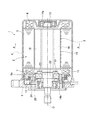
以下、本発明の実施の形態を図面に基づいて詳細に説明する。図1は、本発明の実施の形態1であるブラシレスモータ1(以下、モータ1と略記する)の断面図、図2は、図1のA−A線に沿った断面図である。モータ1は、ロータのマグネットが放射状に配置された所謂スポーク型の磁束集中型モータとなっており、例えば電動パワーステアリング装置の駆動源として使用される。モータ1は、図1に示すように、外側にステータ(固定子)2、内側にロータ(回転子)3を配したインナーロータ型のブラシレスモータとなっている。
(Embodiment 1)
Hereinafter, embodiments of the present invention will be described in detail with reference to the drawings. 1 is a cross-sectional view of a brushless motor 1 (hereinafter abbreviated as “
ステータ2は、有底円筒形状のモータケース4(以下、ケース4と略記する)の内側に接着剤等の固定手段により固定されている。ステータ2は、ステータコア5と、ステータコア5のティース9に巻装されたステータコイル6(以下、コイル6と略記する)及びステータコア5に取り付けられコイル6と電気的に接続されるバスバーユニット(端子ユニット)7とから構成されている。ケース4は、鉄等にて有底円筒状に形成されており、その開口部には、図示しない固定ネジによって、ブラケット8(例えば、アルミダイキャスト製)が取り付けられる。
The
ステータコア5は、鋼製の板材(例えば、電磁鋼板)を積層して形成されており、複数個(本実施形態においては12個)のティース9が径方向内側に向かって突設されている。隣接するティース9の間にはスロット31が形成され、その中にはコイル6が収容されている。ステータコア5には合成樹脂製のインシュレータ11が取り付けられており、インシュレータ11の外側にコイル6が巻装されている。これにより、本ステータ2は12極(12スロット)構成となっている。
The
ステータコア5のケース4の開口側の一端側には、バスバーユニット7が取り付けられている。バスバーユニット7は、合成樹脂製の本体部内に銅製のバスバーがインサート成形された構成となっている。バスバーユニット7の周囲には、複数個の給電用端子12が径方向に突設されている。バスバーユニット7の取り付けに際し、給電用端子12は、ステータコア5から引き出されたコイル6の端部6aが溶接される。バスバーユニット7では、バスバーはモータ1の相数に対応した個数(ここでは、U相,V相,W相分の3個と各相同士の接続用の1個の計4個)設けられている。各コイル6は、その相に対応した給電用端子12と電気的に接続される。ステータコア5は、バスバーユニット7を取り付けた後、ケース4内に圧入固定される。
A bus bar unit 7 is attached to one end of the
ステータ2の内側にはロータ3が挿入されている。ロータ3はロータシャフト13を有しており、ロータシャフト13はベアリング14a,14bによって回転自在に軸支されている。ベアリング14aはケース4の底部中央に、ベアリング14bはブラケット8の中央部にそれぞれ固定されている。ロータシャフト13には、円筒形状のロータコア15と、回転角度検出手段であるレゾルバ21のロータ(レゾルバロータ)22が取り付けられている。レゾルバ21のステータ(レゾルバステータ)23は、合成樹脂製のレゾルバブラケット24に収容されており、取付ネジ25によってブラケット8の内側に固定される。
A
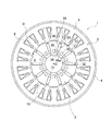
ロータコア15は、磁性体にて形成された薄板状のコアプレート(鋼板材)を複数枚積層させた構成となっており、その外形は真円形ではなく偏芯形状となっている。ロータコア15には、軸孔(中心孔)32と、複数個のマグネット取付孔(マグネット収容部)33が設けられている。軸孔32はロータコア15の中心部に形成されており、そこにはロータシャフト13が圧入固定される。マグネット取付孔33は、径方向に沿って延びる長方形状の孔であり、10個が周方向等間隔に放射状に配置されている(10極構成)。マグネット取付孔33の径方向内側と外側は共に閉鎖されており、径方向外側にはブリッジ部35が形成されている。各マグネット取付孔33内には直方体状のマグネット36がそれぞれ収容され、接着剤等の固定手段にて固定されている。隣接するマグネット36は、対向する面が同極性となっている。マグネット取付孔33よりも径方向内側には、コアプレートを所定位置に積層するための複数のボス孔34が軸方向にプレス打出し加工にて設けられている。各ボス孔34は、平面視で直径がn3の丸形に形成され、軸孔32とマグネット取付孔33との間には、積層されるコアプレートの板厚以上の間隔n4がそれぞれ空くように設定されている。各ボス孔34をこのように設定することで、プレス加工時にコアプレートの不用意な変形を抑制することができる。
The
図3は、マグネット取付孔33近傍の構成を示す説明図である。ロータコア15では、隣接するマグネット取付孔33の間の外周は、半径Rの外形に形成されている。半径Rの中心O1は、ロータ3の中心Oよりも外径側にずれた位置に偏芯配置されている。半径Rの部位、すなわち、隣接するマグネット取付孔33の間の部分は、対向するマグネット36からの磁束が反発し合って径方向外側に流れる疑似磁極部37となっている。疑似磁極部37は、上述のようにそれぞれ半径Rにて偏芯形成されているため、ロータコア15の外周は、マグネット取付孔33部分を谷、疑似磁極部37部分を山とする凹凸形状となり、疑似磁極部37はロータコア15上に突極状に形成される。マグネット取付孔33内の径方向内側部分には、マグネット36が存在しない空隙部(第1磁気抵抗部)38が形成されている。
FIG. 3 is an explanatory diagram showing a configuration in the vicinity of the
マグネット36の径方向内側にこのような空隙部38を設けることにより、同一マグネット36における異極間(反対面のN,S極間)の磁気抵抗が大きくなる。つまり、空隙部38の存在により、マグネット36では、径方向内側における異極間の延面距離(図3の破線T)が長くなり、その分、N,S極をショートカットする磁路が長くなる。このため、マグネット36の径方向内側部位の磁気抵抗が大きくなり、当該部位における漏れ磁束が低減する。
Providing such a
また、空隙部38は、その径方向の長さVLが大きいほど延面距離が長くなり、漏れ磁束低減効果が増す。このため、空隙部38の長さVLは、加工可能な限界まで大きいことが望ましい。図4(a)に示すように、発明者らの実験では、マグネット36の幅が2mmの場合、ほとんど空隙のない従来構造に対し、空隙大(VL:1.7mm)では7%、特大(VL:3.2mm)では13%のトルクアップが図られた。そこで、モータ1では、空隙部38が、ボス孔34と干渉しない範囲、あるいは、ロータシャフト13の圧入代としてコアプレートの板厚以上が確保できる範囲で最大限大きく形成されている。従って、空隙部38は、ロータ3の軸孔32からコアプレートの板厚以上離れてボス孔34を介し、前記ボス孔34からコアプレートの板厚以上離れた位置に設けられている。なお、空隙部38は、単純な四角形である必要はなく、ボス孔34を避けるように、空隙部38の内端38aは、多角形状や曲線孔状に形成することもできる。
Further, the
一方、本発明によるモータ1では、隣接するマグネット取付孔33の中間位置に空隙溝(第2磁気抵抗部)39がさらに設けられている。図2,3に示すように、空隙溝39は長方形状の貫通孔であり、マグネット取付孔33から周方向にコアプレートの板厚以上離れた位置に形成されている。また、空隙溝39の外端39aと内端39bにはそれぞれ、次のような上限位置Y1と下限位置Y2が設定されている。
On the other hand, in the
(a)上限位置Y1
マグネット36の径方向内側の端面36aから、マグネット36の径方向長Lの1/8の位置を示す。空隙溝39はこの上限位置Y1より内周側に設けられる。発明者らの実験によれば、この1/8という上限値は、マグネット長Lが異なる場合でも同様の値を適用できる。また、空隙溝39の外端39aをL/8位置よりも外周側に配すると、径方向外側に向かう磁束の流れが妨げられ、却ってトルクが低下する。つまり、上限位置Y1は、空隙溝39によって、マグネット36から径方向外側に向かう磁束の流れが妨げられないような位置として設定されている。
(A) Upper limit position Y1
A
(b)下限位置Y2
ロータシャフト13の圧入代が確保できる範囲を示す。空隙溝39はこの下限位置Y2より外周側に設けられる。ここで、本実施形態のロータコア15は10極構成のため、各マグネット取付孔33間のロータコア15の中心からの角度は36°となるが、ロータコア15の径やマグネット36の大きさ等を考慮すると、空隙溝39の幅bは、マグネット取付孔33の幅よりも小さくすることで下限位置Y2を、空隙部38の内端38aよりも軸孔32側に近接させて設定できる。一方で、下限位置Y2は、コアプレートの板厚よりも大きい寸法となるように設定されており、これにより、プレス加工時にコアプレートの不用意な変形を抑制することができる。また、マグネット取付孔33の軸孔32側の端面38aと軸孔32の間の寸法をn2とすると、n2は以下の関係となるように設定されている。
n2=n3+n4×2
また、下限位置Y2と軸孔32との間の寸法n1は、空隙部内端38aと軸孔32との間の寸法n2と以下の関係となるように設定されている。
n1≦n2
(B) Lower limit position Y2
The range which can ensure the press-fitting allowance of the
n2 = n3 + n4 × 2
The dimension n1 between the lower limit position Y2 and the
n1 ≦ n2
このような空隙溝39を設けることにより、マグネット取付孔33間(矢示W部分)の面積が減少し、マグネット36の径方向内側部位の磁気抵抗がさらに増大する。このため、この部位における磁束密度が高まり磁気飽和がさらに生じ易くなり、マグネット36の漏れ磁束も低減する。図4(b)に示すように、発明者らの実験では、空隙溝39がないものに比して、上下限位置一杯に空隙溝39を設けたものでは15%のトルクアップが図られた。また、空隙部38のみを設ける場合よりも、空隙溝39を設ける場合の方がトルクアップ効果は大きいが、両者を共に設けることがより望ましい。但し、空隙溝39の方がレイアウト上も設け易く、ロータ強度も維持し易い。なお、空隙部38や空隙溝39は、ボス孔34の有無に関わらず形成可能である。
By providing such a
このように、モータ1では、マグネット取付孔33の径方向内端側に空隙部38、マグネット取付孔33間に空隙溝39を設けると共に、この空隙溝39を、マグネット36の径方向内側端面36aからL/8の位置よりも内周側に設けることにより、径方向外側に向かう磁束の流れを妨げることなく、マグネット36の径方向内側部位における磁気抵抗を増大できる。また、マグネット取付孔33の径方向内側にボス孔34を設けることにより、この部分の磁路を減少し、さらにマグネット36の径方向内側部位における磁気抵抗を増大できる。これにより、当該部位における漏れ磁束が低減され、従来の磁束集中型ブラシレスモータに比して、マグネットの磁束を効率良く使うことができ、マグネット量を増やすことなくトルクの増大を図ることが可能となる。
As described above, in the
(実施の形態2)
次に、本発明の実施形態2について説明する。図5,6は、実施の形態2であるブラシレスモータのロータ構造を示す説明図である。なお、以下の実施形態では、実施の形態1と同様の部材、部分については同一の符号を付し、その説明は省略する。
(Embodiment 2)
Next,
先の実施の形態1では、マグネット取付孔33の内外端が共に閉鎖されている構成を示したが、このような構成の前記ロータ3では、ブリッジ部35を介して磁束がショートカットされてしまう可能性がある。この場合、図5のように、マグネット取付孔33の外周側を開放させた構成とれば、磁束のショートカットは防止できる。但し、マグネット取付孔33の外周側を完全に開放すると、コギングが増大するおそれがある。そこで、図6に示すように、マグネット取付孔33の径方向外端を一部切り欠いて開口部42を設けると共に、ロータ41の外周に鍔部43を設けることにより、磁束のショートカットを抑えつつ、コギングの増大を防止しても良い。なお、図5,6のロータ41は14極構成となっており、空隙溝39の内周側にボス孔34が配置されている。
In the first embodiment, the configuration in which the inner and outer ends of the
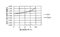
鍔部43は、隣接する疑似磁極部37の少なくとも一方から、疑似磁極部37の外周面37aに連続する形で延出形成されている。この場合、モータ回転方向によってどちらの側から延出させるかが決定され(回転方向と反対側に向かって延出させる)、正逆転するモータでは両方から鍔部43を延出させる。鍔部43を設けた場合、マグネット取付孔33の開口部42は、概ねコアプレートの板厚程度かそれよりも小さく設定される。図7は、開口部42の幅Zとトルク及びリップルの関係を示した説明図である。図7に示すように、トルクは開口部42の幅Zを広げるほど増大するが、リップルは開口部42の幅Zを広げ過ぎると急激に大きくなる。そこで、図7の結果から、開口部42の幅Zは、マグネット36の幅(=マグネット取付孔33の幅)に対して75%以下、すなわち、開口部42は開口率75%(マグネット36の幅が2mmの場合、1.5mm以下)が望ましい。
The
また、ロータ41では、マグネット取付孔33に非磁性体(例えば、合成樹脂)製のスペーサ(非磁性部)44が取り付けられている。スペーサ44は、マグネット取付孔33の内側の空隙部38と外側の空隙45に共に装着されている。スペーサ44は棒状に形成されており、ロータ3の端面から、軸方向に沿ってマグネット取付孔33内に挿入される。このようなスペーサ44をマグネット取付孔33に取り付けることにより、マグネット36が遠心力によって移動することがない。また、図6の構成では、鍔部43がストッパとしても機能するため、マグネット36の飛散も防止できる。
In the
本発明は前記実施形態に限定されるものではなく、その要旨を逸脱しない範囲で種々変更可能であることは言うまでもない。
例えば、前記実施形態では、10極12スロットのブラシレスモータに本発明を適用した例を示したが、本発明は、磁束集中型ブラシレスモータであれば、8極や14極など、ロータ極数には関係なく広く適用可能である。また、前記実施形態では、ロータコア15の外形が偏芯形状となったものを示したが、本発明は、偏芯のない外形が円形のロータコアを有するブラシレスモータにも適用可能である。さらに、本発明によるブラシレスモータは、電動パワーステアリング装置以外にも、ハイブリッド車や電気自動車などの他の電気機械・機器にも適用可能である。
It goes without saying that the present invention is not limited to the above-described embodiment, and various modifications can be made without departing from the scope of the invention.
For example, in the above-described embodiment, an example in which the present invention is applied to a 10
1 ブラシレスモータ
2 ステータ
3 ロータ
4 モータケース
5 ステータコア
6 ステータコイル
6a 端部
7 バスバーユニット
8 ブラケット
9 ティース
11 インシュレータ
12 給電用端子
13 ロータシャフト
14a,14b ベアリング
15 ロータコア
21 レゾルバ
22 レゾルバロータ
23 レゾルバステータ
24 レゾルバブラケット
25 取付ネジ
31 スロット
32 軸孔(中心孔)
33 マグネット取付孔(マグネット収容部)
34 ボス孔
35 ブリッジ部
36 マグネット
36a 径方向内側端面
37 疑似磁極部
37a 外周面
38 空隙部(第1磁気抵抗部)
38a 内端
39 空隙溝(第2磁気抵抗部)
39a 外端
39b 内端
41 ロータ
42 開口部
43 鍔部
44 スペーサ(非磁性部)
45 空隙
51 ロータ
52 マグネット
52a 径方向内側部分
53 コア部材
54 疑似磁極部
L マグネット径方向長
O ロータ中心
O1 疑似磁極部半径中心
R 疑似磁極部半径
Y1 空隙溝上限位置
Y2 空隙溝下限位置
n1 空隙溝下限位置と軸孔との間の寸法
n2 空隙部内端と軸孔との間の寸法
n3 ボス孔の径寸法
n4 ボス孔と軸孔との間、ボス孔とマグネット取付孔との間の寸法
b 空隙溝の幅
Z 開口部の幅
DESCRIPTION OF
33 Magnet mounting hole (magnet housing)
34
39a
45
Claims (9)
前記ステータの内側に回転自在に配置され、複数の極を構成するマグネットが、放射状に形成されたマグネット収容部内に収容されてなるロータと、を有するブラシレスモータであって、
前記ロータは、隣接する前記マグネット収容部間に形成される複数個の疑似磁極部と、前記マグネット収容部の径方向内端と前記マグネットの径方向内端との間に形成された第1磁気抵抗部と、前記疑似磁極部の内周側中央部に形成された第2磁気抵抗部と、を有し、
前記第2磁気抵抗部は、前記マグネットの径方向長さをLとしたとき、該マグネットの径方向内側の端面からL/8の位置よりも内周側にそれぞれ設けられることを特徴とするブラシレスモータ。 A stator comprising a plurality of teeth projecting radially inward, and a coil wound around the teeth via a slot formed between the teeth;
A brushless motor having a rotor that is rotatably arranged inside the stator and that has a plurality of poles and is housed in a radially formed magnet housing portion,
The rotor includes a plurality of pseudo magnetic pole portions formed between adjacent magnet housing portions, and a first magnet formed between a radially inner end of the magnet housing portion and a radially inner end of the magnet. A resistance portion, and a second magnetic resistance portion formed at the inner peripheral side central portion of the pseudo magnetic pole portion,
The brushless, wherein the second magnetoresistive portion is provided on the inner peripheral side of the L / 8 position from the radially inner end face of the magnet when the radial length of the magnet is L. motor.
前記ロータは、磁性材料にて形成されたコアプレートを複数枚積層して形成されており、
前記第1磁気抵抗部は、前記ロータの中央に形成された中心孔から前記コアプレートの板厚以上離れて設けられることを特徴とするブラシレスモータ。 The brushless motor according to claim 1,
The rotor is formed by laminating a plurality of core plates made of a magnetic material,
The brushless motor according to claim 1, wherein the first magnetoresistive portion is provided away from a center hole formed at a center of the rotor by a thickness equal to or greater than a thickness of the core plate.
前記ロータは、磁性材料にて形成されたコアプレートを複数枚積層して形成されており、
前記第2磁気抵抗部は、隣接する前記マグネット収容部から前記コアプレートの板厚以上離れて設けられることを特徴とするブラシレスモータ。 The brushless motor according to claim 1 or 2,
The rotor is formed by laminating a plurality of core plates made of a magnetic material,
The brushless motor according to claim 1, wherein the second magnetoresistive part is provided away from the adjacent magnet housing part by a thickness equal to or greater than the thickness of the core plate.
前記第2磁気抵抗部の径方向内端と前記ロータの中央に形成された中心孔との間の距離は、前記第1磁気抵抗部の径方向内端と前記中心孔との間の距離と同じかそれ以下であることを特徴とするブラシレスモータ。 The brushless motor according to any one of claims 1 to 3,
The distance between the radially inner end of the second magnetoresistive portion and the center hole formed in the center of the rotor is the distance between the radially inner end of the first magnetoresistive portion and the center hole. Brushless motor characterized by being the same or less.
前記マグネット収容部の径方向外端に、前記ロータの外周面に臨んで開口する開口部を設けたことを特徴とするブラシレスモータ。 In the brushless motor according to any one of claims 1 to 4,
A brushless motor, wherein an opening that opens toward the outer peripheral surface of the rotor is provided at a radially outer end of the magnet housing portion.
前記開口部に、隣り合う前記疑似磁極部の少なくとも一方から、該疑似磁極部の外周面に連続する鍔部を延出形成したことを特徴とするブラシレスモータ。 The brushless motor according to claim 5, wherein
A brushless motor, wherein a flange that extends from an outer peripheral surface of the pseudo magnetic pole portion is formed to extend from at least one of the adjacent pseudo magnetic pole portions in the opening.
前記開口部は、前記マグネット収容部の周方向に沿った幅に対する開口率が75%以下であることを特徴とするブラシレスモータ。 The brushless motor according to claim 5 or 6,
The brushless motor, wherein the opening has an opening ratio of 75% or less with respect to a width along the circumferential direction of the magnet housing portion.
前記マグネット収容部内の前記マグネットの径方向内側部分と径方向外側部分にそれぞれ非磁性部を設けたことを特徴とするブラシレスモータ。 In the brushless motor according to any one of claims 1 to 7,
A brushless motor, wherein a nonmagnetic portion is provided in each of a radially inner portion and a radially outer portion of the magnet in the magnet housing portion.
前記非磁性部は、合成樹脂にて構成されることを特徴とするブラシレスモータ。 The brushless motor according to claim 8,
The brushless motor, wherein the nonmagnetic part is made of a synthetic resin.
Priority Applications (1)
| Application Number | Priority Date | Filing Date | Title |
|---|---|---|---|
| JP2013024056A JP2014155357A (en) | 2013-02-12 | 2013-02-12 | Brushless motor |
Applications Claiming Priority (1)
| Application Number | Priority Date | Filing Date | Title |
|---|---|---|---|
| JP2013024056A JP2014155357A (en) | 2013-02-12 | 2013-02-12 | Brushless motor |
Publications (1)
| Publication Number | Publication Date |
|---|---|
| JP2014155357A true JP2014155357A (en) | 2014-08-25 |
Family
ID=51576724
Family Applications (1)
| Application Number | Title | Priority Date | Filing Date |
|---|---|---|---|
| JP2013024056A Pending JP2014155357A (en) | 2013-02-12 | 2013-02-12 | Brushless motor |
Country Status (1)
| Country | Link |
|---|---|
| JP (1) | JP2014155357A (en) |
Cited By (6)
| Publication number | Priority date | Publication date | Assignee | Title |
|---|---|---|---|---|
| JP2016165167A (en) * | 2015-03-06 | 2016-09-08 | 株式会社ミツバ | Brushless motor |
| JPWO2017195263A1 (en) * | 2016-05-10 | 2018-09-27 | 三菱電機株式会社 | Permanent magnet type motor |
| JP2021132501A (en) * | 2020-02-20 | 2021-09-09 | パナソニックIpマネジメント株式会社 | Motors and power tools |
| CN115360868A (en) * | 2022-09-13 | 2022-11-18 | 重庆长安新能源汽车科技有限公司 | Low-voltage wire harness integrated mounting structure for oil cooling driving motor |
| JPWO2023079679A1 (en) * | 2021-11-05 | 2023-05-11 | ||
| WO2023195331A1 (en) * | 2022-04-05 | 2023-10-12 | ニデックプレシジョン株式会社 | Electric motor and method for manufacturing same |
Citations (6)
| Publication number | Priority date | Publication date | Assignee | Title |
|---|---|---|---|---|
| JP2005287285A (en) * | 2004-03-03 | 2005-10-13 | Asmo Co Ltd | Motor |
| JP2006087287A (en) * | 2004-09-17 | 2006-03-30 | Lg Electronics Inc | Magnetic flux concentrating motor |
| JP2009177944A (en) * | 2008-01-24 | 2009-08-06 | Calsonic Kansei Corp | Motor |
| JP2011055619A (en) * | 2009-09-01 | 2011-03-17 | Mitsubishi Electric Corp | Permanent magnet type dynamo-electric machine |
| US20120112591A1 (en) * | 2009-05-28 | 2012-05-10 | Robert Bosch Gmbh | Electric machine |
| JP2012217269A (en) * | 2011-03-31 | 2012-11-08 | Hitachi Appliances Inc | Rotor, magnet motor, and washing machine |
-
2013
- 2013-02-12 JP JP2013024056A patent/JP2014155357A/en active Pending
Patent Citations (6)
| Publication number | Priority date | Publication date | Assignee | Title |
|---|---|---|---|---|
| JP2005287285A (en) * | 2004-03-03 | 2005-10-13 | Asmo Co Ltd | Motor |
| JP2006087287A (en) * | 2004-09-17 | 2006-03-30 | Lg Electronics Inc | Magnetic flux concentrating motor |
| JP2009177944A (en) * | 2008-01-24 | 2009-08-06 | Calsonic Kansei Corp | Motor |
| US20120112591A1 (en) * | 2009-05-28 | 2012-05-10 | Robert Bosch Gmbh | Electric machine |
| JP2011055619A (en) * | 2009-09-01 | 2011-03-17 | Mitsubishi Electric Corp | Permanent magnet type dynamo-electric machine |
| JP2012217269A (en) * | 2011-03-31 | 2012-11-08 | Hitachi Appliances Inc | Rotor, magnet motor, and washing machine |
Cited By (11)
| Publication number | Priority date | Publication date | Assignee | Title |
|---|---|---|---|---|
| JP2016165167A (en) * | 2015-03-06 | 2016-09-08 | 株式会社ミツバ | Brushless motor |
| JPWO2017195263A1 (en) * | 2016-05-10 | 2018-09-27 | 三菱電機株式会社 | Permanent magnet type motor |
| US10916983B2 (en) | 2016-05-10 | 2021-02-09 | Mitsubishi Electric Corporation | Permanent-magnet motor |
| JP2021132501A (en) * | 2020-02-20 | 2021-09-09 | パナソニックIpマネジメント株式会社 | Motors and power tools |
| JP7281674B2 (en) | 2020-02-20 | 2023-05-26 | パナソニックIpマネジメント株式会社 | motors and power tools |
| JPWO2023079679A1 (en) * | 2021-11-05 | 2023-05-11 | ||
| WO2023079679A1 (en) * | 2021-11-05 | 2023-05-11 | 株式会社 東芝 | Rotor for rotary electric machine |
| JP7404557B2 (en) | 2021-11-05 | 2023-12-25 | 株式会社東芝 | rotor of rotating electric machine |
| US12424888B2 (en) | 2021-11-05 | 2025-09-23 | Kabushiki Kaisha Toshiba | Rotor of rotary electric machine |
| WO2023195331A1 (en) * | 2022-04-05 | 2023-10-12 | ニデックプレシジョン株式会社 | Electric motor and method for manufacturing same |
| CN115360868A (en) * | 2022-09-13 | 2022-11-18 | 重庆长安新能源汽车科技有限公司 | Low-voltage wire harness integrated mounting structure for oil cooling driving motor |
Similar Documents
| Publication | Publication Date | Title |
|---|---|---|
| US9071118B2 (en) | Axial motor | |
| JP5722301B2 (en) | Embedded magnet type synchronous motor rotor and embedded magnet type synchronous motor | |
| WO2016047476A1 (en) | Brushless motor | |
| CN103339829A (en) | Brushless motor and electric device mounted with same | |
| JP2015033244A (en) | Brushless motor | |
| JP2014155357A (en) | Brushless motor | |
| JP2014003841A (en) | Rotor and rotary electric machine using the same | |
| US8860271B2 (en) | Rotating electric machine | |
| TWI661654B (en) | Stator core and permanent magnet motor | |
| JP2014239633A (en) | Rotor core for motor and brushless motor | |
| WO2020110191A1 (en) | Rotating electrical machine | |
| JPWO2017212575A1 (en) | Permanent magnet motor | |
| WO2014020756A1 (en) | Dynamo-electric machine | |
| JP2009213283A (en) | Brushless motor | |
| JP2014007939A (en) | Brushless motor | |
| JP2014107939A (en) | Brushless motor | |
| WO2016060232A1 (en) | Double stator-type rotary machine | |
| JP5702118B2 (en) | Rotor structure and motor | |
| WO2019198462A1 (en) | Motor and brushless wiper motor | |
| JP5975786B2 (en) | Magnet-assisted reluctance motor rotor and brushless motor | |
| JP5193094B2 (en) | Permanent magnet motor | |
| JP6944675B2 (en) | Rotor and permanent magnet type rotary electric machine | |
| JP5290726B2 (en) | motor | |
| JP6695241B2 (en) | Brushless motor | |
| JP2016171660A (en) | Rotating electrical machine rotor |
Legal Events
| Date | Code | Title | Description |
|---|---|---|---|
| A621 | Written request for application examination |
Free format text: JAPANESE INTERMEDIATE CODE: A621 Effective date: 20151224 |
|
| A977 | Report on retrieval |
Free format text: JAPANESE INTERMEDIATE CODE: A971007 Effective date: 20160929 |
|
| A131 | Notification of reasons for refusal |
Free format text: JAPANESE INTERMEDIATE CODE: A131 Effective date: 20161004 |
|
| A02 | Decision of refusal |
Free format text: JAPANESE INTERMEDIATE CODE: A02 Effective date: 20170404 |