JP2014155509A - Radiographic system - Google Patents
Radiographic system Download PDFInfo
- Publication number
- JP2014155509A JP2014155509A JP2011130709A JP2011130709A JP2014155509A JP 2014155509 A JP2014155509 A JP 2014155509A JP 2011130709 A JP2011130709 A JP 2011130709A JP 2011130709 A JP2011130709 A JP 2011130709A JP 2014155509 A JP2014155509 A JP 2014155509A
- Authority
- JP
- Japan
- Prior art keywords
- image
- ray
- radiation
- grating
- partial
- Prior art date
- Legal status (The legal status is an assumption and is not a legal conclusion. Google has not performed a legal analysis and makes no representation as to the accuracy of the status listed.)
- Withdrawn
Links
Images



Classifications
-
- A—HUMAN NECESSITIES
- A61—MEDICAL OR VETERINARY SCIENCE; HYGIENE
- A61B—DIAGNOSIS; SURGERY; IDENTIFICATION
- A61B6/00—Apparatus or devices for radiation diagnosis; Apparatus or devices for radiation diagnosis combined with radiation therapy equipment
- A61B6/42—Arrangements for detecting radiation specially adapted for radiation diagnosis
- A61B6/4291—Arrangements for detecting radiation specially adapted for radiation diagnosis the detector being combined with a grid or grating
-
- A—HUMAN NECESSITIES
- A61—MEDICAL OR VETERINARY SCIENCE; HYGIENE
- A61B—DIAGNOSIS; SURGERY; IDENTIFICATION
- A61B6/00—Apparatus or devices for radiation diagnosis; Apparatus or devices for radiation diagnosis combined with radiation therapy equipment
- A61B6/48—Diagnostic techniques
- A61B6/484—Diagnostic techniques involving phase contrast X-ray imaging
-
- A—HUMAN NECESSITIES
- A61—MEDICAL OR VETERINARY SCIENCE; HYGIENE
- A61B—DIAGNOSIS; SURGERY; IDENTIFICATION
- A61B6/00—Apparatus or devices for radiation diagnosis; Apparatus or devices for radiation diagnosis combined with radiation therapy equipment
- A61B6/52—Devices using data or image processing specially adapted for radiation diagnosis
- A61B6/5205—Devices using data or image processing specially adapted for radiation diagnosis involving processing of raw data to produce diagnostic data
-
- G—PHYSICS
- G21—NUCLEAR PHYSICS; NUCLEAR ENGINEERING
- G21K—HANDLING OF PARTICLES OR IONISING RADIATION NOT OTHERWISE PROVIDED FOR; IRRADIATION DEVICES; GAMMA RAY OR X-RAY MICROSCOPES
- G21K2207/00—Particular details of imaging devices or methods using ionizing electromagnetic radiation such as X-rays or gamma rays
- G21K2207/005—Methods and devices obtaining contrast from non-absorbing interaction of the radiation with matter, e.g. phase contrast
Landscapes
- Health & Medical Sciences (AREA)
- Life Sciences & Earth Sciences (AREA)
- Engineering & Computer Science (AREA)
- Medical Informatics (AREA)
- Radiology & Medical Imaging (AREA)
- Molecular Biology (AREA)
- Biophysics (AREA)
- Nuclear Medicine, Radiotherapy & Molecular Imaging (AREA)
- Optics & Photonics (AREA)
- Pathology (AREA)
- Physics & Mathematics (AREA)
- Biomedical Technology (AREA)
- Heart & Thoracic Surgery (AREA)
- High Energy & Nuclear Physics (AREA)
- Surgery (AREA)
- Animal Behavior & Ethology (AREA)
- General Health & Medical Sciences (AREA)
- Public Health (AREA)
- Veterinary Medicine (AREA)
- Computer Vision & Pattern Recognition (AREA)
- Apparatus For Radiation Diagnosis (AREA)
- Radiography Using Non-Light Waves (AREA)
Abstract
Description
本発明は、放射線撮影システムに関する。 The present invention relates to a radiation imaging system.
X線は、物質を構成する元素の原子番号と、物質の密度及び厚さとに依存して減衰するといった特性を有することから、被写体の内部を透視するためのプローブとして用いられている。X線を用いた撮影は、医療診断や非破壊検査等の分野において広く普及している。 X-rays are used as a probe for seeing through the inside of a subject because they have characteristics such as attenuation depending on the atomic numbers of elements constituting the substance and the density and thickness of the substance. X-ray imaging is widely used in fields such as medical diagnosis and non-destructive inspection.
一般的なX線撮影システムでは、X線を放射するX線源とX線画像を検出するX線画像検出器との間に被写体を配置して、被写体の透過像を撮影する。この場合、X線源からX線画像検出器に向けて放射された各X線は、X線画像検出器までの経路上に存在する被写体を構成する物質の特性(原子番号、密度、厚さ)の差異に応じた量の減衰(吸収)を受けた後、X線画像検出器に入射する。この結果、被写体のX線透過像がX線画像検出器により検出され画像化される。X線画像検出器としては、X線増感紙とフイルムとの組み合わせや輝尽性蛍光体(蓄積性蛍光体)のほか、半導体回路を用いたフラットパネル検出器(FPD:Flat Panel Detector)が広く用いられている。 In a general X-ray imaging system, a subject is placed between an X-ray source that emits X-rays and an X-ray image detector that detects an X-ray image, and a transmission image of the subject is captured. In this case, each X-ray radiated from the X-ray source toward the X-ray image detector has characteristics (atomic number, density, thickness) of the substance constituting the subject existing on the path to the X-ray image detector. ), The light is incident on the X-ray image detector. As a result, an X-ray transmission image of the subject is detected and imaged by the X-ray image detector. X-ray image detectors include a combination of X-ray intensifying screens and films, stimulable phosphors (accumulative phosphors), and flat panel detectors (FPD) using semiconductor circuits. Widely used.
しかし、X線吸収能は、原子番号が小さい元素からなる物質ほど低くなり、生体軟部組織やソフトマテリアルなどでは、X線吸収能の差が小さく、従ってX線透過像としての十分な画像の濃淡(コントラスト)が得られないといった問題がある。例えば、人体の関節を構成する軟骨部とその周辺の関節液は、いずれも殆どの成分が水であり、両者のX線の吸収量の差が小さいため、画像のコントラストが得られにくい。 However, the X-ray absorptivity becomes lower as a substance composed of an element having a smaller atomic number, and the difference in the X-ray absorptivity is small in a soft tissue or soft material of a living body. There is a problem that (contrast) cannot be obtained. For example, most of the components of the cartilage part constituting the joint of the human body and the joint fluid in the vicinity thereof are water, and the difference in the amount of X-ray absorption between the two is small, so that it is difficult to obtain image contrast.
このような問題を背景に、近年、被写体によるX線の強度変化に代えて、被写体によるX線の位相変化(角度変化)に基づいた画像(以下、位相コントラスト画像と称する)を得るX線位相イメージングの研究が盛んに行われている。一般に、X線が物体に入射したとき、X線の強度よりも位相のほうが高い相互作用を示すことが知られている。このため、位相差を利用したX線位相イメージングでは、X線吸収能が低い弱吸収物体であっても高コントラストの画像を得ることができる。このようなX線位相イメージングの一種として、近年、2枚の透過回折格子(位相型格子及び吸収型格子)とX線画像検出器とからなるX線タルボ干渉計を用いたX線撮影システムが考案されている(例えば、特許文献1参照)。 Against the background of such problems, in recent years, an X-ray phase for obtaining an image (hereinafter referred to as a phase contrast image) based on an X-ray phase change (angle change) by an object instead of an X-ray intensity change by an object. Imaging research is actively conducted. In general, it is known that when X-rays are incident on an object, the interaction is higher in phase than in X-ray intensity. For this reason, in the X-ray phase imaging using the phase difference, a high-contrast image can be obtained even for a weakly absorbing object having a low X-ray absorption capability. As a kind of such X-ray phase imaging, in recent years, an X-ray imaging system using an X-ray Talbot interferometer comprising two transmission diffraction gratings (phase grating and absorption grating) and an X-ray image detector has been proposed. It has been devised (for example, see Patent Document 1).
X線タルボ干渉計は、被写体の背後に第1の回折格子(位相型格子あるいは吸収型格子)を配置し、第1の回折格子の格子ピッチとX線波長で決まる特定距離(タルボ干渉距離)だけ下流に第2の回折格子(吸収型格子)を配置し、その背後にX線画像検出器を配置することにより構成される。上記タルボ干渉距離とは、第1の回折格子を通過したX線が、タルボ干渉効果によって、周期的強度分布を呈する自己像(以下、G1像という)を形成する距離であり、このG1像は、X線源と第1の回折格子との間に配置された被写体とX線との相互作用(位相変化)により変調を受ける。 In the X-ray Talbot interferometer, a first diffraction grating (phase type grating or absorption type grating) is arranged behind a subject, and a specific distance (Talbot interference distance) determined by the grating pitch of the first diffraction grating and the X-ray wavelength. The second diffraction grating (absorption type grating) is disposed only downstream, and the X-ray image detector is disposed behind the second diffraction grating. The Talbot interference distance is a distance at which X-rays that have passed through the first diffraction grating form a self-image (hereinafter referred to as a G1 image) that exhibits a periodic intensity distribution due to the Talbot interference effect. And modulated by the interaction (phase change) between the subject and the X-rays disposed between the X-ray source and the first diffraction grating.
X線タルボ干渉計では、G1像と第2の回折格子との重ね合わせにより生じるモアレ縞を検出し、モアレ縞に対応して画像に現れる周期パターンの被写体による変調を解析することによって被写体の位相情報を取得する。画像に現れる周期パターンの解析方法としては、たとえば、縞走査法が知られている。この縞走査法によると、第1の回折格子に対して第2の回折格子を、第1の回折格子の面にほぼ平行で、かつ第1の回折格子の格子方向(条帯方向)にほぼ垂直な方向に、格子ピッチを等分割した走査ピッチで並進移動させながら複数回の撮影を行い、得られる複数の画像データ間で対応する画素毎の信号値の変化から、被写体で屈折したX線の角度分布(位相シフトの微分像)を取得し、この角度分布に基づいて被写体の位相コントラスト画像を得ることができる。 In the X-ray Talbot interferometer, the moiré fringes generated by the superposition of the G1 image and the second diffraction grating are detected, and the phase of the subject is analyzed by analyzing the modulation of the periodic pattern appearing in the image corresponding to the moire fringes. Get information. For example, a fringe scanning method is known as a method for analyzing a periodic pattern appearing in an image. According to this fringe scanning method, the second diffraction grating is substantially parallel to the surface of the first diffraction grating with respect to the first diffraction grating and substantially in the grating direction (strip direction) of the first diffraction grating. X-rays refracted by the subject from a change in signal value for each corresponding pixel between a plurality of image data obtained by performing a plurality of times of imaging while translating in a vertical direction with a scanning pitch obtained by equally dividing the lattice pitch. Angle distribution (differential image of phase shift) can be obtained, and a phase contrast image of the subject can be obtained based on this angle distribution.
しかし、上記の縞走査法によると、複数回の撮影を行う必要があり、撮影中の被写体の移動、それによる画質の低下が懸念される。そこで、フーリエ変換及び逆フーリエ変換を用いることによって1回の撮影で被写体の位相情報を取得する方法が提案されている(例えば、特許文献2参照)。これは、周期パターン含む画像をフーリエ変換して得られる空間周波数スペクトルから周期パターンの基本周波数成分を含む周波数領域を分離し、分離された周波数領域に対して逆フーリエ変換を行うことによって位相シフトの微分像を取得するものである。それによれば、複数回の撮影の間の格子の移動と、高精度が要求されるその移動機構が不要であるため、撮影ワークフローの向上と装置の簡易化が可能になる。また、各撮影間の被写体の移動に起因する画質低下を解消することができる。 However, according to the above-described fringe scanning method, it is necessary to perform image capturing a plurality of times, and there is a concern about movement of a subject during image capturing and a decrease in image quality due to the movement. In view of this, a method has been proposed in which the phase information of the subject is acquired by one shooting by using Fourier transform and inverse Fourier transform (see, for example, Patent Document 2). This is done by separating the frequency domain containing the fundamental frequency component of the periodic pattern from the spatial frequency spectrum obtained by Fourier transforming the image containing the periodic pattern, and performing the inverse Fourier transform on the separated frequency domain. A differential image is acquired. According to this, the movement of the lattice between a plurality of times of photographing and the moving mechanism that requires high accuracy are unnecessary, so that the photographing workflow can be improved and the apparatus can be simplified. In addition, it is possible to eliminate the deterioration in image quality caused by the movement of the subject between each photographing.
特許文献1及び2に記載されたX線撮影システムにおいて、視野を拡大するには第1及び第2の回折格子も相応に大きなものが必要となる。しかし、第1及び第2の回折格子は、典型的にはμmオーダーの格子ピッチで高アスペクト比に構成される必要があるため、大サイズで高精度なものを製造することは非常に困難である。そこで、第1及び第2の回折格子、並びにX線画像検出器の各々を、複数の格子モジュールないし複数の検出器モジュールに分割して構成するようにしたX線撮影システムも提案されている(特許文献3参照)。 In the X-ray imaging systems described in Patent Documents 1 and 2, the first and second diffraction gratings need to be correspondingly large in order to expand the field of view. However, the first and second diffraction gratings typically need to be configured with a high aspect ratio with a grating pitch on the order of μm, so that it is very difficult to manufacture a large size and high accuracy. is there. Therefore, an X-ray imaging system in which each of the first and second diffraction gratings and the X-ray image detector is divided into a plurality of grating modules or a plurality of detector modules has been proposed ( (See Patent Document 3).
また、第2の回折格子を用いることなく、G1像の周期的強度分布の周期よりも小さい画素ピッチの検出器を用いてG1像の周期的強度分布を検出し、このG1像の周期的強度分布の変調を解析することによって、被写体の位相情報を取得するようにしたX線撮影システムも提案されている(特許文献4参照)。 Further, the periodic intensity distribution of the G1 image is detected using a detector having a pixel pitch smaller than the period of the periodic intensity distribution of the G1 image without using the second diffraction grating, and the periodic intensity of the G1 image is detected. There has also been proposed an X-ray imaging system that acquires phase information of an object by analyzing distribution modulation (see Patent Document 4).
特許文献4に記載されたX線撮影システムは、G1像の周期的強度分布の周期よりも小さい画素ピッチの検出器を用いてG1像の周期的強度分布を検出し、これを解析して位相情報を取得しており、画素ピッチが小さいことから空間分解能に優れる。そして、第2の回折格子を介さないことから位相情報の精度の向上が図られる。しかしながら、画素ピッチが微小な検出器は、比較的小サイズのものに限られ、視野が制限される。また、検出器のサイズを大きくすると、典型的には、S/Nが低下する傾向にあり、S/Nの低下に起因して位相情報の精度が低下する懸念がある。 The X-ray imaging system described in Patent Document 4 detects the periodic intensity distribution of the G1 image using a detector having a pixel pitch smaller than the period of the periodic intensity distribution of the G1 image, analyzes this, and analyzes the phase. Since the information is acquired and the pixel pitch is small, the spatial resolution is excellent. Further, since the second diffraction grating is not interposed, the accuracy of the phase information can be improved. However, a detector with a small pixel pitch is limited to a relatively small size, and the field of view is limited. Further, when the size of the detector is increased, typically, the S / N tends to decrease, and there is a concern that the accuracy of the phase information may decrease due to the decrease in S / N.
そこで、特許文献3に記載されたX線撮影システムのように、検出器を複数の検出器モジュールに分割して構成するようにすれば、微細な画素ピッチで、かつS/Nに優れた大サイズの検出器を得ることができる。しかしながら、全ての検出器モジュールを第1の回折格子に対して全く同じ相対位置関係に配置することは非常に困難であり、このような相対位置関係の不一致は、画像における周期パターンの周期や向きのズレとして現れる。 Therefore, if the detector is divided into a plurality of detector modules as in the X-ray imaging system described in Patent Document 3, it is possible to achieve a large pixel pitch and excellent S / N. A size detector can be obtained. However, it is very difficult to arrange all the detector modules in exactly the same relative positional relationship with respect to the first diffraction grating, and such a mismatch in relative positional relationship is caused by the period and direction of the periodic pattern in the image. Appears as a misalignment.
そして、画像における周期パターンの周期や向きが一様でない画像に対して、フーリエ変換及び逆フーリエ変換を用いて解析を行った場合に、被写体の位相情報を正確に得ることができない虞がある。これは、複数の検出器モジュールを連結して構成する場合に限られず、複数の格子モジュールを連結して第1の回折格子や第2の回折格子を構成する場合にも妥当する。 Then, when an analysis is performed using Fourier transform and inverse Fourier transform on an image in which the period and direction of the periodic pattern in the image are not uniform, there is a possibility that the phase information of the subject cannot be obtained accurately. This is not limited to a case where a plurality of detector modules are connected and configured, and is also applicable to a case where a plurality of grating modules are connected to form the first diffraction grating and the second diffraction grating.
本発明は、上述した事情に鑑みなされたものであり、フーリエ変換及び逆フーリエ変換を用いて被写体の位相情報を取得する放射線位相イメージングにおいて、位相情報の精度を高めることを目的とする。 The present invention has been made in view of the above-described circumstances, and an object thereof is to improve the accuracy of phase information in radiation phase imaging that acquires phase information of a subject using Fourier transform and inverse Fourier transform.
放射線照射野に配置される被写体によって変調を受けた周期パターンを含む放射線画像を取得する撮影部と、前記放射線画像に含まれる前記周期パターンに基づいて前記被写体の位相コントラスト画像を生成する演算処理部と、を備え、前記撮影部は、通過する放射線によって、前記放射線画像に含まれる前記周期パターンの基礎となる周期的強度分布を含む放射線像を形成する一つ以上の格子と、前記放射線像を検出する放射線画像検出器と、を有しており、前記格子及び前記放射線画像検出器の要素のうち少なくとも一つの要素は、複数のモジュールに分割されて構成されており、前記演算処理部は、モジュール分割された前記要素のうち少なくとも一つの要素におけるモジュール間の境界の少なくとも一部に対応させて前記放射線画像を複数の部分放射線画像に区分し、これらの部分放射線画像毎に、前記部分放射線画像に対してフーリエ変換を行って該部分放射線画像の空間周波数スペクトルを取得する変換処理と、前記部分放射線画像に含まれる周期パターンの基本周波数成分を含む空間周波数領域を前記空間周波数スペクトルから分離し、分離された前記空間周波数領域に対して逆フーリエ変換を行って部分位相コントラスト画像を生成する部分位相コントラスト画像生成処理と、を実行し、そして、前記部分位相コントラスト画像生成処理によって生成される複数の部分位相コントラスト画像を結合して前記被写体の位相コントラスト画像を生成する結合処理を実行する、放射線撮影システム。 An imaging unit that acquires a radiation image including a periodic pattern modulated by a subject arranged in a radiation field, and an arithmetic processing unit that generates a phase contrast image of the subject based on the periodic pattern included in the radiation image The imaging unit includes, by radiation passing therethrough, one or more gratings that form a radiation image including a periodic intensity distribution that is a basis of the periodic pattern included in the radiation image, and the radiation image A radiation image detector for detecting, and at least one of the lattice and the elements of the radiation image detector is divided into a plurality of modules, and the arithmetic processing unit includes: The radiation image corresponding to at least a part of a boundary between modules in at least one of the elements divided into modules. The partial radiation image is divided into a plurality of partial radiation images, and for each partial radiation image, a Fourier transform is performed on the partial radiation image to obtain a spatial frequency spectrum of the partial radiation image, and included in the partial radiation image A partial phase contrast image generation process that separates a spatial frequency region including a fundamental frequency component of a periodic pattern from the spatial frequency spectrum and generates a partial phase contrast image by performing inverse Fourier transform on the separated spatial frequency region And a combining process for generating a phase contrast image of the object by combining a plurality of partial phase contrast images generated by the partial phase contrast image generating process.
本発明によれば、格子や放射線画像検出器を複数のモジュールに分割して構成することにより、格子については、その精度を低下させることなく大サイズのものを得ることができ、放射線画像検出器については、そのS/Nを低下させることなく大サイズのものを得ることができ、視野を容易に拡大することができる。 According to the present invention, by dividing the grating and the radiographic image detector into a plurality of modules, it is possible to obtain a large-size grating without reducing the accuracy thereof. Can be obtained in a large size without reducing its S / N, and the field of view can be easily enlarged.
そして、放射線画像検出器によって取得される放射線画像を、モジュール分割された要素におけるモジュール間の境界に対応させて部分X線画像に区分し、部分X線画像毎に周期パターンを解析して被写体の位相シフト分布を取得することにより、この要素のモジュールの各々の他の要素に対する相対位置関係のズレに起因して生じる部分X線画像間の周期パターンの周期や向きの非一様性が被写体の位相シフト分布に与える影響を排除ないし低減し、得られる被写体の位相シフト分布の精度を高めることができる。 Then, the radiographic image acquired by the radiographic image detector is divided into partial X-ray images corresponding to the boundaries between the modules in the module-divided elements, and the periodic pattern is analyzed for each partial X-ray image to analyze the subject. By acquiring the phase shift distribution, non-uniformity in the period and orientation of the periodic pattern between the partial X-ray images caused by the relative positional deviation of each of the modules of this element relative to the other elements is obtained. The influence on the phase shift distribution can be eliminated or reduced, and the accuracy of the obtained phase shift distribution of the subject can be increased.
図1は、本発明の実施形態を説明するための放射線撮影システムの一例の構成を示し、図2は、図1の放射線撮影システムの制御ブロックを示す。 FIG. 1 shows a configuration of an example of a radiation imaging system for explaining an embodiment of the present invention, and FIG. 2 shows a control block of the radiation imaging system of FIG.
X線撮影システム10は、被写体(患者)Hを立位状態で撮影するX線診断装置であって、被写体HにX線を放射するX線源11と、X線源11に対向配置され、X線源11から被写体Hを透過したX線を検出して画像データを生成する撮影部12と、操作者の操作に基づいてX線源11の曝射動作や撮影部12の撮影動作を制御するとともに、撮影部12により取得された画像データを演算処理して位相コントラスト画像を生成するコンソール13とに大別される。
The
X線源11は、天井から吊り下げられたX線源保持装置14により上下方向(x方向)に移動自在に保持されている。撮影部12は、床上に設置された立位スタンド15により上下方向に移動自在に保持されている。
The
X線源11は、X線源制御部17の制御に基づき、高電圧発生器16から印加される高電圧に応じてX線を発生するX線管18と、X線管18から発せられたX線のうち、被写体Hの検査領域に寄与しない部分を遮蔽するように照射野を制限する可動式のコリメータ19aを備えたコリメータユニット19とから構成されている。X線管18は、陽極回転型であり、電子放出源(陰極)としてのフィラメント(図示せず)から電子線を放出して、所定の速度で回転する回転陽極18aに衝突させることによりX線を発生する。この回転陽極18aの電子線の衝突部分がX線焦点18bとなる。
Based on the control of the X-ray
X線源保持装置14は、天井に設置された天井レール(図示せず)により水平方向(z方向)に移動自在に構成された台車部14aと、上下方向に連結された複数の支柱部14bとからなる。台車部14aには、支柱部14bを伸縮させて、X線源11の上下方向に関する位置を変更するモータ(図示せず)が設けられている。
The X-ray
立位スタンド15は、床に設置された本体15aに、撮影部12を保持する保持部15bが上下方向に移動自在に取り付けられている。保持部15bは、上下方向に離間して配置された2つのプーリ15cの間に掛架された無端ベルト15dに接続され、プーリ15cを回転させるモータ(図示せず)により駆動される。このモータの駆動は、操作者の設定操作に基づき、後述するコンソール13の制御装置20により制御される。
In the standing
また、立位スタンド15には、プーリ15c又は無端ベルト15dの移動量を計測することにより、撮影部12の上下方向に関する位置を検出するポテンショメータ等の位置センサ(図示せず)が設けられている。この位置センサの検出値は、ケーブル等によりX線源保持装置14に供給される。X線源保持装置14は、供給された検出値に基づいて支柱部14bを伸縮させ、撮影部12の上下動に追従するようにX線源11を移動させる。
Further, the standing
コンソール13には、CPU、ROM、RAM等からなる制御装置20が設けられている。制御装置20には、操作者が撮影指示やその指示内容を入力する入力装置21と、撮影部12により取得された画像データを演算処理してX線画像を生成する演算処理部22と、X線画像を記憶する記憶部23と、X線画像等を表示するモニタ24と、X線撮影システム10の各部と接続されるインターフェース(I/F)25とがバス26を介して接続されている。
The
入力装置21としては、例えば、スイッチ、タッチパネル、マウス、キーボード等を用いることが可能であり、入力装置21の操作により、X線管電圧やX線照射時間等のX線撮影条件、撮影タイミング等が入力される。モニタ24は、液晶ディスプレイ等からなり、制御装置20の制御により、X線撮影条件等の文字やX線画像を表示する。
As the
撮影部12には、X線画像検出器30、被写体HによるX線の位相変化(角度変化)を検出し位相イメージングを行うための第1の吸収型格子31及び第2の吸収型格子32が設けられている。
The
図3及び図4は、撮影部12の構成を模式的に示す。
3 and 4 schematically show the configuration of the photographing
X線画像検出器30は、検出面がX線源11から照射されるX線の光軸Aに直交するように配置されている。第1及び第2の吸収型格子31,32は、X線画像検出器30とX線源11との間に配置されている。
The
第1の吸収型格子31は、複数の第1の格子モジュール33を連結して構成されており、第2の吸収型格子32もまた、複数の第2の格子モジュール36が連結されて構成されている。図示の例では、第1の吸収型格子31は、第1の格子モジュール33が光軸Aに直交する面内においてx方向及びy方向にそれぞれ4つずつ配列され、隣り合う第1の格子モジュール33同士が連結されて、構成されている。第2の吸収型格子32は、第2の格子モジュール36が光軸Aに直交する面内においてx方向及びy方向にそれぞれ5つずつ配列され、隣り合う第2の格子モジュール36同士が連結されて、構成されている。なお、第1の吸収型格子31における第1の格子モジュール33の配列、及び第2の吸収型格子32における第2の格子モジュール36の配列は、上記の例に限らず、x方向又はy方向の一次元状の配列であってもよい。
The first absorption type grating 31 is configured by connecting a plurality of first
第1の格子モジュール33の各々は、基板34と、この基板34に配置された複数のX線遮蔽部35とから構成されている。第2の格子モジュール36の各々は、基板37と、この基板37に配置された複数のX線遮蔽部38とから構成されている。基板34,37は、いずれもX線を透過させるシリコンやガラス、樹脂等のX線透過性部材により形成されている。
Each of the
X線遮蔽部35,38は、いずれもX線源11から照射されるX線の光軸Aに直交する面内の一方向(図示の例では、y方向)に延伸した線状の部材で構成される。各X線遮蔽部35,38の材料としては、X線吸収性に優れるものが好ましく、例えば、金、白金等の重金属であることが好ましい。これらのX線遮蔽部35,38は、金属メッキ法や蒸着法によって形成することが可能である。
The
X線遮蔽部35は、X線の光軸Aに直交する面内において、上記一方向と直交する方向(x方向)に一定の周期p1で、互いに所定の間隔d1を空けて配列されている。同様に、X線遮蔽部38は、X線の光軸Aに直交する面内において、上記一方向と直交する方向(x方向)に一定の周期p2で、互いに所定の間隔d2を空けて配列されている。このような第1及び第2の吸収型格子31,32は、入射X線に位相差を与えるものでなく、強度差を与えるものであるため、振幅型格子とも称される。なお、スリット部(上記間隔d1,d2の領域)は空隙でなくてもよく、例えば、高分子や軽金属などのX線低吸収材で該空隙を充填してもよい。
The
第1及び第2の吸収型格子31,32は、タルボ干渉効果の有無に係らず、スリット部を通過したX線を幾何学的に投影するように構成されている。具体的には、間隔d1,d2を、X線源11から照射されるX線のピーク波長より十分大きな値とすることで、照射X線に含まれる大部分のX線をスリット部で回折させずに、直進性を保ったまま通過するように構成する。例えば、前述の回転陽極18aとしてタングステンを用い、管電圧を50kVとした場合には、X線のピーク波長は、約0.4Åである。この場合には、間隔d1,d2を、1〜10μm程度とすれば、スリット部で大部分のX線が回折されずに幾何学的に投影される。
The first and
X線源11から放射されるX線は、平行ビームではなく、X線焦点18bを発光点としたコーンビームであるため、第1の吸収型格子31を通過して射影される投影像(以下、この投影像をG1像と称する)は、X線焦点18bからの距離に比例して拡大される。第2の吸収型格子32の格子ピッチp2及び間隔d2は、そのスリット部が、第2の吸収型格子32の位置におけるG1像の周期的強度分布とほぼ一致するように決定されている。すなわち、X線焦点18bから第1の吸収型格子31までの距離をL1、第1の吸収型格子31から第2の吸収型格子32までの距離をL2とした場合に、格子ピッチp2は、次式(1)の関係を満たすように決定される。
The X-ray emitted from the

第1の吸収型格子31から第2の吸収型格子32までの距離L2は、タルボ干渉計では、第1の回折格子の格子ピッチとX線波長とで決まるタルボ干渉距離に制約されるが、本X線撮影システム10の撮影部12では、第1の吸収型格子31が入射X線を回折させずに投影させる構成であって、第1の吸収型格子31のG1像が、第1の吸収型格子31の後方のすべての位置で相似的に得られるため、該距離L2を、タルボ干渉距離と無関係に設定することができる。
In the Talbot interferometer, the distance L 2 from the first absorption type grating 31 to the second absorption type grating 32 is limited to the Talbot interference distance determined by the grating pitch of the first diffraction grating and the X-ray wavelength. The
上記のように撮影部12は、タルボ干渉計を構成するものではないが、第1の吸収型格子31でX線を回折したと仮定した場合のタルボ干渉距離Zは、第1の吸収型格子31の格子ピッチp1、第2の吸収型格子32の格子ピッチp2、X線波長(ピーク波長)λ、及び正の整数mを用いて、次式(2)で表される。
As described above, the
式(2)は、X線源11から照射されるX線がコーンビームである場合のタルボ干渉距離を表す式であり、「Atsushi Momose, et al., Japanese Journal of Applied Physics, Vol.47, No.10, 2008年10月, 8077頁」により知られている。
Expression (2) is an expression representing the Talbot interference distance when the X-rays emitted from the
本X線撮影システム10では、撮影部12の薄型化を目的とし、上記距離L2を、m=1の場合の最小のタルボ干渉距離Zより短い値に設定する。すなわち、上記距離L2は、次式(3)を満たす範囲の値に設定される。
In the present
なお、X線源11から照射されるX線が実質的に平行ビームとみなせる場合のタルボ干渉距離Zは次式(4)となり、上記距離L2を、次式(5)を満たす範囲の値に設定する。
Incidentally, Talbot distance Z by the following equation (4) and in the case of X-rays emitted from the
ただし、必ずしも上記距離L2は、式(3)ないし式(5)を満たす必要はなく、例えば撮影部12の薄型化の要請がない場合などには、式(3)ないし式(5)から外れる範囲の値も採り得る。
However, not always the distance L 2 need not satisfy equation (3) through (5), for example, when there is no demand for thinning of the
X線遮蔽部35,38は、コントラストの高い周期的強度分布のX線像を生成するためには、X線を完全に遮蔽(吸収)することが好ましいが、上記したX線吸収性に優れる材料(金、白金等)を用いたとしても、吸収されずに透過するX線が少なからず存在する。このため、X線の遮蔽性を高めるためには、X線遮蔽部35,38bのそれぞれの厚みh1,h2を、可能な限り厚くすることが好ましい。例えば、X線管18の管電圧が50kVの場合に、照射X線の90%以上を遮蔽することが好ましく、この場合には、厚みh1,h2は、金(Au)換算で30μm以上であることが好ましい。
The X-ray shields 35 and 38 preferably shield (absorb) X-rays completely in order to generate an X-ray image having a periodic intensity distribution with high contrast, but are excellent in the X-ray absorbability described above. Even if materials (gold, platinum, etc.) are used, there are not a few X-rays that are transmitted without being absorbed. For this reason, in order to improve the shielding property of X-rays, it is preferable to make the thicknesses h 1 and h 2 of the
一方、X線遮蔽部35,38の厚みh1,h2を厚くし過ぎると、斜めに入射するX線がスリット部を通過しにくくなり、いわゆるケラレが生じて、X線遮蔽部35,38の延伸方向(条帯方向)に直交する方向(x方向)の有効視野が狭くなるといった問題がある。このため、視野確保の観点から、厚みh1,h2の上限を規定する。X線画像検出器30の検出面におけるx方向の有効視野の長さVを確保するには、X線焦点18bからX線画像検出器30の検出面までの距離をLとすると、厚みh1,h2は、図4に示す幾何学的関係から、次式(6)及び(7)を満たすように設定する必要がある。
On the other hand, if the thicknesses h 1 and h 2 of the
例えば、d1=2.5μm、d2=3.0μmであり、通常の病院での撮影を想定して、L=2mとした場合には、x方向の有効視野の長さVとして10cmの長さを確保するには、厚みh1は100μm以下、厚みh2は120μm以下とすればよい。 For example, when d 1 = 2.5 μm and d 2 = 3.0 μm, and assuming L = 2 m assuming normal hospital imaging, the effective visual field length V in the x direction is 10 cm. In order to ensure the length, the thickness h 1 may be 100 μm or less and the thickness h 2 may be 120 μm or less.
以上の構成において、第1の吸収型格子31のG1像に第2の吸収型格子32が重ね合わされて、第2の吸収型格子32の直後に配置されたX線画像検出器30上にX線像が形成される。第2の吸収型格子32の位置におけるG1像の周期的強度分布の周期p1’と、第2の吸収型格子32の実質的な格子ピッチp2’(製造後の実質的なピッチ)とは、製造誤差や配置誤差により若干の差異が生じる。このうち、配置誤差とは、第1及び第2の吸収型格子31,32が、相対的に傾斜や回転、両者の間隔が変化することによりx方向への実質的なピッチが変化することを意味している。
In the above configuration, the second absorption grating 32 is superimposed on the G1 image of the first absorption grating 31, and the
G1像の周期的強度分布の周期p1’と第2の吸収型格子32の格子ピッチp2’との微小な差異により、X線画像検出器30上に形成されるX線像は周期的強度分布としてのモアレ縞を含む。このモアレ縞のx方向に関する周期Tは、次式(8)で表される。
The X-ray image formed on the
G1像の周期的強度分布の周期p1’に比べてモアレ縞の周期Tは大きくなることから、これを解像するのに必要となる画素の配列ピッチの点で、X線画像検出器30に対する制約は緩和される。そこで、本例においては、X線画像検出器30として、画素の配列ピッチは比較的粗大であるが、単一のモジュールで大サイズの検出器を比較的容易に構成することのできるTFT(Thin Film Transistor)パネルをベースとしたFPDが用いられている。
Since the period T of the moire fringes is larger than the period p 1 ′ of the periodic intensity distribution of the G1 image, the
図5は、X線画像検出器30の構成を模式的に示す。
FIG. 5 schematically shows the configuration of the
X線画像検出器30は、ガラス基板等の絶縁性基板上に、X線を電荷に変換して蓄積する複数の画素40、及び各画素40に蓄積された電荷を読み出す読み出し回路を構成する複数のTFTスイッチ(図示せず)がxy方向に2次元配列されてなる受像部41と、受像部41からの電荷の読み出しタイミングを制御する走査回路42と、各画素40から読み出された電荷を画像データに変換して記憶する信号処理回路43と、画像データをコンソール13のI/F25を介して演算処理部22に送信するデータ送信回路44とから構成されている。
The
各画素40は、アモルファスセレン等の変換層(図示せず)でX線を電荷に直接変換し、変換された電荷を下部の電極に接続されたキャパシタ(図示せず)に蓄積する直接変換型の素子として構成することができる。各画素40には、TFTスイッチが接続され、TFTスイッチのゲート電極が走査線45、ソース電極がキャパシタ、ドレイン電極が信号線46に接続される。TFTスイッチが走査回路42からの駆動パルスによってON状態になると、キャパシタに蓄積された電荷が信号線46に読み出される。
Each
なお、各画素40は、テルビウム賦活酸化ガドリニウム(Gd2O2S:Tb)やタリウム賦活ヨウ化セシウム(CsI:Tl)等からなるシンチレータ(図示せず)でX線を一旦可視光に変換し、変換された可視光をフォトダイオード(図示せず)で電荷に変換して蓄積する間接変換型のX線検出素子として構成することも可能である。
Each
信号処理回路43は、積分アンプ回路、A/D変換器、補正回路、及び画像メモリにより構成されている。積分アンプ回路は、各画素40から信号線46を介して出力された電荷を積分して電圧信号(画像信号)に変換して、A/D変換器に入力する。A/D変換器は、入力された画像信号をデジタルの画像データに変換して補正回路に入力する。補正回路は、画像データに対して、オフセット補正、ゲイン補正、及びリニアリティ補正を行い、補正後の画像データを画像メモリに記憶させる。なお、補正回路による補正処理として、X線の露光量や露光分布(いわゆるシェーディング)の補正や、X線画像検出器30の制御条件(駆動周波数や読み出し期間)に依存するパターンノイズ(例えば、TFTスイッチのリーク信号)の補正等を含めてもよい。
The
なお、X線画像検出器30としては、TFTパネルをベースとしたFPDに限られず、CCDセンサやCMOSセンサ等の固体撮像素子をベースとした各種のX線画像検出器を用いることも可能である。
The
X線画像検出器30上に形成されるモアレ縞を、このX線画像検出器30で検出するには、画素40のx方向に関する配列ピッチPは、次式(9)を満たすことが好ましい。
In order for the
式(9)は、画素40の配列ピッチPをモアレ周期Tより小さくすることを意味している。
Expression (9) means that the arrangement pitch P of the
画素40の配列ピッチPは、設計的に定められた値(一般的に100μm程度)であり変更することが困難であるため、画素40の配列ピッチPとモアレ周期Tとの大小関係を調整するには、第1及び第2の吸収型格子31,32の位置調整を行い、G1像のパターン周期p1’と第2の吸収型格子32の格子ピッチp2’との少なくともいずれか一方を変更することによりモアレ周期Tを変更することが好ましい。
Since the arrangement pitch P of the
図6に、モアレ周期Tを変更する方法を模式的に示す。 FIG. 6 schematically shows a method of changing the moire cycle T.
モアレ周期Tの変更は、第1及び第2の吸収型格子31,32のいずれか一方を、光軸Aを中心として相対的に回転させることにより行うことができる。例えば、第1の吸収型格子31に対して、第2の吸収型格子32を、光軸Aを中心として相対的に回転させる相対回転機構50を設ける。この相対回転機構50により、第2の吸収型格子32を角度θだけ回転させると、第2の吸収型格子32のx方向に関する実質的な格子ピッチは、「p2’」→「p2’/cosθ」と変化し、この結果、モアレ周期Tが変化する(FIG.6A)。
The moire period T can be changed by relatively rotating one of the first and
別の例として、モアレ周期Tの変更は、第1及び第2の吸収型格子31,32のいずれか一方を、光軸Aに直交し、かつy方向に沿う方向の軸を中心として相対的に傾斜させることにより行うことができる。例えば、第1の吸収型格子31に対して、第2の吸収型格子32を、光軸Aに直交し、かつy方向に沿う方向の軸を中心として相対的に傾斜させる相対傾斜機構51を設ける。この相対傾斜機構51により、第2の吸収型格子32を角度αだけ傾斜させると、第2の吸収型格子32のx方向に関する実質的な格子ピッチは、「p2’」→「p2’×cosα」と変化し、この結果、モアレ周期Tが変化する(FIG.6B)。
As another example, the change of the moire period T is such that either one of the first and second
更に別の例として、モアレ周期Tの変更は、第1及び第2の吸収型格子31,32のいずれか一方を光軸Aの方向に沿って相対的に移動させることにより行うことができる。例えば、第1の吸収型格子31と第2の吸収型格子32との間の距離L2を変更するように、第1の吸収型格子31に対して、第2の吸収型格子32を、光軸Aの方向に沿って相対的に移動させる相対移動機構52を設ける。この相対移動機構52により、第2の吸収型格子32を光軸Aに移動量δだけ移動させると、第2の吸収型格子32の位置に投影される第1の吸収型格子31のG1像のパターン周期は、「p1’」→「p1’×(L1+L2+δ)/(L1+L2)」と変化し、この結果、モアレ周期Tが変化する(FIG.6C)。
As another example, the moire period T can be changed by relatively moving one of the first and
本X線撮影システム10において、撮影部12は、上述のようにタルボ干渉計ではなく、距離L2を自由に設定することができるため、相対移動機構52のように距離L2の変更によりモアレ周期Tを変更する機構を、好適に採用することができる。モアレ縞の周期Tを変更するための第1及び第2の吸収型格子31,32の上記変更機構(相対回転機構50、相対傾斜機構51、及び相対移動機構52)は、圧電素子等のアクチュエータにより構成することが可能である。なお、以上は、x方向に関する画素40の配列ピッチ及びモアレ縞の周期について説明したが、y方向に関する画素40の配列ピッチ及びモアレ縞の周期についても同様であり、y方向に関する画素40の配列ピッチはモアレ縞の周期よりも小さいことが好ましく、上記変更機構(相対回転機構50、相対傾斜機構51、及び相対移動機構52)と同様の機構によって、y方向に関する画素40の配列ピッチとモアレ縞の周期との大小関係についても調整することができる。
In the
X線源11と第1の吸収型格子31との間に被写体Hを配置した場合に、X線画像検出器30上に形成されるモアレ縞は、被写体Hにより変調を受ける。この変調量は、被写体Hによる屈折効果によって偏向したX線の角度に比例する。このモアレ縞をX線画像検出器30によって検出して取得される画像には、モアレ縞に対応する周期パターンが含まれ、この周期パターンを解析することによって、被写体Hの位相コントラスト画像を生成することができる。
When the subject H is arranged between the
次に、画像の周期パターンの解析方法について説明する。 Next, a method for analyzing a periodic pattern of an image will be described.
図7は、被写体Hのx方向に関する位相シフト分布Φ(x)に応じて屈折される1つのX線を示す。 FIG. 7 shows one X-ray refracted according to the phase shift distribution Φ (x) of the subject H in the x direction.
符号55は、被写体Hが存在しない場合に直進するX線の経路を示しており、この経路55を進むX線は、第1及び第2の吸収型格子31,32を通過してX線画像検出器30に入射する。符号56は、被写体Hが存在する場合に、被写体Hにより屈折されて偏向したX線の経路を示している。この経路56を進むX線は、第1の吸収型格子31を通過した後、第2の吸収型格子32より遮蔽される。
被写体Hの位相シフト分布Φ(x)は、被写体Hの屈折率分布をn(x,z)、zをX線の進む方向として、次式(10)で表される。 The phase shift distribution Φ (x) of the subject H is expressed by the following equation (10), where n (x, z) is the refractive index distribution of the subject H, and z is the direction in which the X-ray travels.
そして、屈折角φは、X線波長λと被写体Hの位相シフト分布Φ(x)を用いて、式(11)で表される。 The refraction angle φ is expressed by Expression (11) using the X-ray wavelength λ and the phase shift distribution Φ (x) of the subject H.
屈折角φ(x)は、式(11)で示したように位相シフト分布の微分値に対応する値であるため、屈折角φ(x)をx軸に沿って積分することにより、位相シフト分布Φ(x)が得られる。なお、上記の説明では、画素40のy方向に関するy座標を考慮していないが、各y座標について同様の演算を行うことにより、x方向及びy方向における2次元的な位相シフト分布Φ(x,y)が得られる。
Since the refraction angle φ (x) is a value corresponding to the differential value of the phase shift distribution as shown in the equation (11), the refraction angle φ (x) is integrated along the x-axis to obtain the phase shift. A distribution Φ (x) is obtained. In the above description, the y coordinate in the y direction of the
ここで、第1及び第2の吸収型格子31、32によって形成されるモアレ縞、つまりは画像の周期パターンは次式(12)で表すことができ、式(12)は次式(13)に書き換えることができる。
Here, the moire fringes formed by the first and second
式(12)において、a(x,y)はバックグラウンドを表し、b(x,y)は周期パターンの基本周期に対応した空間周波数成分の振幅を表し、(f0x、f0y)は周期パターンの基本周期を表す。また式(13)において、c(x,y)は次式(14)で表される。 In Expression (12), a (x, y) represents the background, b (x, y) represents the amplitude of the spatial frequency component corresponding to the basic period of the periodic pattern, and (f 0x, f 0y ) represents the period. Represents the basic period of the pattern. In the formula (13), c (x, y) is represented by the following formula (14).
従って、c(x,y)又はc*(x,y)の成分を取り出すことによって屈折角φ(x,y)の情報を得ることができる。ここで、式(13)はフーリエ変換によって次式(15)となる。 Therefore, information on the refraction angle φ (x, y) can be obtained by extracting the component of c (x, y) or c * (x, y). Here, equation (13) becomes the following equation (15) by Fourier transform.
式(15)において、F(fx,fy)、A(fx,fy)、C(fx,fy)は、それぞれf(x,y)、a(x,y)、c(x,y)に対する2次元のフーリエ変換である。 In the formula (15), F (f x , f y), A (f x, f y), C (f x, f y) , respectively f (x, y), a (x, y), c It is a two-dimensional Fourier transform for (x, y).
第1及び第2の吸収型格子31,32のような1次元格子を使用した場合に、画像の空間周波数スペクトルには、少なくとも、A(fx,fy)に由来するピークと、これを挟んでC(fx,fy)及びC*(fx,fy)に由来する周期パターンの基本周期に対応した空間周波数成分のピークとの3つのピークが生じる。A(fx,fy)に由来するピークは原点に、また、C(fx,fy)及びC*(fx,fy)に由来するピークは(±f0x,±f0y)(複合同順)の位置に生じる。
When using the one-dimensional lattice such as the first and second
画像の空間周波数スペクトルから屈折角φ(x、y)を得るには、周期パターンの基本周期に対応する空間周波数成分のピーク周波数を含む領域を切り出し、ピーク周波数が周波数空間の原点に重なるように切り出した領域を移動させ、逆フーリエ変換を行う。そして、逆フーリエ変換によって得られる複素数情報から屈折角φ(x,y)を得ることができる。 In order to obtain the refraction angle φ (x, y) from the spatial frequency spectrum of the image, a region including the peak frequency of the spatial frequency component corresponding to the basic period of the periodic pattern is cut out so that the peak frequency overlaps the origin of the frequency space. Move the clipped area and perform inverse Fourier transform. Then, the refraction angle φ (x, y) can be obtained from the complex number information obtained by the inverse Fourier transform.
ここで、第1の吸収型格子31は複数の第1の格子モジュール33を連結して構成され、第2の吸収型格子32もまた、複数の第2の格子モジュール36を連結して構成されている。そのため、第2の吸収型格子32やX線画像検出器30に対する第1の格子モジュール33の各々の相対位置関係がズレる場合があり、同様に、第1の吸収型格子31やX線画像検出器30に対する第2の格子モジュール36の各々の相対位置関係がズレる場合がある。このような相対位置関係の不一致は、X線画像検出器30によって取得された画像の各部における周期パターンの周期や向きのズレとして現れる。そこで、第1の吸収型格子31における第1の格子モジュール33間の境界の少なくとも一部、及び/又は第2の吸収型格子32における第2の格子モジュール36間の境界の少なくとも一部に対応させて、X線画像検出器30によって取得されたX線画像を複数の部分X線画像に区分し、これらの部分X線画像毎に上記の周期パターンの解析を行う。
Here, the first absorption type grating 31 is configured by connecting a plurality of first
図8は、X線画像の区分の一例、及び区分された部分X線画像に基づく位相コントラスト画像の生成処理を示す。 FIG. 8 shows an example of segmentation of an X-ray image and a phase contrast image generation process based on the segmented partial X-ray image.
図8に示す例は、第1の吸収型格子31における第1の格子モジュール33間の境界の全てに対応させて、X線画像を4×4の計16の部分X線画像Img1,1,Img2,1,・・・,Img4,4に区分したものである(FIG.8A)。具体的には、第1の吸収型格子31において、第1の格子モジュール33間の境界は、x方向に延びる境界線Lx1,Lx2,Lx3(図3参照)、及びy方向に延びる境界線Ly1,Ly2,Ly3(図3参照)によって定義され、これらの境界線Lx1〜3,Ly1〜3のX線画像検出器30上への投影である境界線Lx’1〜3,Ly’1〜3に沿ってX線画像を部分X線画像Img1,1,Img1,2,・・・,Img4,4に区分している。
The example shown in FIG. 8 corresponds to all the boundaries between the first
そして、区分された部分X線画像Img1,1,Img2,1,・・・,Img4,4毎に、上記の周期パターンの解析を行うことによって、部分位相シフト分布Φ1,1,Φ2,1,・・・,Φ4,4が得られる。そして、得られた部分位相シフト分布Φ1,1,Φ2,1,・・・,Φ4,4を結合することによって、被写体Hの位相シフト分布Φが得られる(FIG.8B)。 Then, by analyzing the periodic pattern for each of the divided partial X-ray images Img 1,1 , Img 2,1 ,..., Img 4,4 , partial phase shift distributions Φ 1,1 , Φ 2,1 ,..., Φ 4,4 are obtained. Then, by combining the obtained partial phase shift distributions Φ 1,1 , Φ 2,1 ,..., Φ 4,4 , the phase shift distribution Φ of the subject H is obtained (FIG. 8B).
このように、第1の吸収型格子31における第1の格子モジュール33間の境界に対応させてX線画像を区分した部分X線画像毎に周期パターンを解析して、被写体Hの位相シフト分布Φを取得することにより、少なくとも、第2の吸収型格子32やX線画像検出器30に対する第1の格子モジュール33の各々の相対位置関係のズレに起因して生じる部分X線画像間の周期パターンの周期や向きの非一様性が被写体Hの位相シフト分布Φに与える影響を排除ないし低減し、得られる被写体Hの位相シフト分布Φの精度を高めることができる。
As described above, the periodic pattern is analyzed for each partial X-ray image obtained by dividing the X-ray image corresponding to the boundary between the first
以上の処理は演算処理部22によって実行され、演算処理部22は、位相シフト分布Φ(x,y)を画像化した位相コントラスト画像を記憶部23に記憶させる。上述した位相コントラスト画像の生成処理は、入力装置21から操作者により撮影指示がなされた後、制御装置20の制御に基づいて各部が連係動作して自動的に行われ、最終的に被写体Hの位相コントラスト画像がモニタ24に表示される。
The above processing is executed by the
図9は、X線画像の区分の他の例を示す。 FIG. 9 shows another example of the division of the X-ray image.
図9に示す例は、第1の吸収型格子31における第1の格子モジュール33間の境界の全て、及び第2の吸収型格子32における第2の格子モジュール36間の境界の全てに対応させて、X線画像を部分X線画像Img1,1,Img2,1,・・・,Img8,8に区分したものである。
The example shown in FIG. 9 corresponds to all the boundaries between the first
具体的には、第1の吸収型格子31において、第1の格子モジュール33間の境界は、x方向に延びる境界線Lx1,Lx2,Lx3、及びy方向に延びる境界線Ly1,Ly2,Ly3によって定義される。また、第2の吸収型格子32において、第2の格子モジュール36間の境界は、x方向に延びる境界線Lx4,Lx5,Lx6,Lx7(図3参照)、及びy方向に延びる境界線Ly4,Ly5,Ly6,Ly7(図3参照)によって定義される。これらの境界線Lx1〜7,Ly1〜7のX線画像検出器30上への投影である境界線Lx’1〜7,Ly’1〜7に沿ってX線画像を部分X線画像Img1,1,Img2,1,・・・,Img8,8に区分している。即ち、Img1,1は第1の格子モジュール331,1と第2の格子モジュール361,1とを通過したX線によって形成されるX線像の画像に相当する。また、Img2,1は第1の格子モジュール331,1と第2の格子モジュール362,1とを通過したX線によって形成されるX線像の画像に相当する。
Specifically, in the first absorption type grating 31, the boundaries between the first
これによれば、第2の吸収型格子32やX線画像検出器30に対する第1の格子モジュール33の各々の相対位置関係のズレに加え、さらに第1の吸収型格子31やX線画像検出器30に対する第2の格子モジュール36の各々の相対位置関係のズレに起因して生じる部分X線画像間の周期パターンの周期や向きの非一様性が被写体Hの位相シフト分布Φに与える影響を排除ないし低減することができ、得られる被写体Hの位相シフト分布Φの精度を一層高めることができる。
According to this, in addition to the shift of the relative positional relationship of each of the first
図10は、X線画像の区分の他の例を示す。 FIG. 10 shows another example of X-ray image segmentation.
図10に示す例は、第1の吸収型格子31における第1の格子モジュール33間の境界の一部に対応させて、X線画像を2×2の計4の部分X線画像Img1,1,Img2,1,Img1,2,Img2,2に区分したものである。具体的には、第1の吸収型格子31において、第1の格子モジュール33間の境界は、x方向に延びる境界線Lx1,Lx2,Lx3(図3参照)、及びy方向に延びる境界線Ly1,Ly2,Ly3(図3参照)によって定義され、これらの境界線Lx1〜3,Ly1〜3のうちLx2及びLy2のX線画像検出器30上への投影である境界線Lx’2,Ly’2に沿ってX線画像を部分X線画像Img1,1,Img2,1,Img1,2,Img2,2に区分している。
The example shown in FIG. 10 corresponds to a part of the boundary between the first
これによれば、図8に示す例に比べて、部分X線画像への区分数を減らして解析プロセスの削減することができ、演算処理部22における処理の高速化を図ることができる。さらに、離散フーリエ変換においては画像サイズと周波数分解能とが比例するという関係があるため、区分数を過度に多くして画像サイズを小さくしすぎるとフーリエ変換後の周波数分解能が下がり、得られる位相シフト部分布Φの精度が低下する場合があるが、このように区分数を適宜調整することにより、画像サイズと比例関係にある周波数分解能を確保し、得られる位相シフト分布Φの精度を確保することもできる。
According to this, compared with the example shown in FIG. 8, the number of divisions into partial X-ray images can be reduced and the analysis process can be reduced, and the processing in the
以上、説明したように、放射線撮影システム10によれば、第1の吸収型格子31や第2の吸収型格子32といった複数のモジュールに分割して構成された要素におけるモジュール間の境界に対応させてX線画像を部分X線画像に区分し、この部分X線画像毎に周期パターンを解析して被写体Hの位相シフト分布Φを取得することにより、モジュール分割された要素を構成するモジュールの各々の他の要素に対する相対位置関係のズレに起因して生じる部分X線画像間の周期パターンの周期や向きの非一様性が被写体Hの位相シフト分布Φに与える影響を排除ないし低減することができ、得られる被写体Hの位相シフト分布Φの精度を高めることができる。
As described above, according to the
また、第1の吸収型格子31で殆どのX線を回折させずに、第2の吸収型格子32に幾何学的に投影するため、照射X線には、高い空間的可干渉性は要求されず、X線源11として医療分野で用いられている一般的なX線源を用いることができる。そして、第1の吸収型格子31から第2の吸収型格子32までの距離L2を任意の値とすることができ、該距離L2を、タルボ干渉計での最小のタルボ干渉距離より小さく設定することができるため、撮影部12を小型化(薄型化)することができる。更に、本X線撮影システムでは、第1の吸収型格子31からの投影像(G1像)には、照射X線のほぼすべての波長成分が寄与し、モアレ縞のコントラストが向上するため、位相コントラスト画像の検出感度を向上させることができる。
Further, since most of the X-rays are not diffracted by the first absorption type grating 31 and geometrically projected onto the second absorption type grating 32, high spatial coherence is required for the irradiated X-rays. Instead, a general X-ray source used in the medical field can be used as the
なお、上述したX線撮影システム10において、X線画像検出器30は単一のモジュールとして構成されているが、第1及び第2の吸収型格子31,32と同様に、複数の検出器モジュールに分割されて構成されることもできる。その場合に、X線画像検出器30によって取得される画像を複数の部分画像に区分する際に、X線画像検出器30における検出器モジュール間の境界の一部又は全部に対応させて区分するようにしてもよい。それによれば、第1の吸収型格子31や第2の吸収型格子32に対する検出器モジュールの各々の相対位置関係のズレに起因して生じる部分X線画像間のモアレ縞の周期や向きの非一様性が被写体Hの位相シフト分布Φに与える影響を排除ないし低減することができる。
In the
また、第1の格子の投影像に対して第2の格子を重ね合わせてモアレ縞を生じさるものであって、そのため、第1及び第2の格子がいずれも吸収型格子であるものとして説明したが、本発明はこれに限定されるものではない。上述のとおり、タルボ干渉像に対して第2の格子を重ね合わせてモアレ縞を生じさせる場合にも、本発明は有用である。よって、第1の格子は、吸収型格子に限らず位相型格子であってもよい。 In addition, the second grating is superimposed on the projection image of the first grating to generate moire fringes, and therefore the first and second gratings are both absorption type gratings. However, the present invention is not limited to this. As described above, the present invention is also useful when the Moire fringes are generated by superimposing the second grating on the Talbot interference image. Therefore, the first grating is not limited to the absorption type grating but may be a phase type grating.
また、位相シフト分布Φを画像化したものを位相コントラスト画像として記憶ないし表示するものとして説明したが、位相シフト分布Φは、屈折角φより求まる位相シフト分布Φの微分量を積分したものであって、屈折角φ及び位相シフト分布Φの微分量もまた被写体によるX線の位相変化に関連している。よって、屈折角φを画像化したもの、また、位相シフトの微分量を画像化したものも位相コントラスト画像に含まれる。 In addition, although the image obtained by imaging the phase shift distribution Φ is described as being stored or displayed as a phase contrast image, the phase shift distribution Φ is obtained by integrating the differential amount of the phase shift distribution Φ obtained from the refraction angle φ. Thus, the differential amount of the refraction angle φ and the phase shift distribution Φ is also related to the X-ray phase change by the subject. Therefore, an image of the refraction angle φ and an image of the differential amount of the phase shift are also included in the phase contrast image.
また、被写体がない状態で撮影(プレ撮影)して取得されるモアレ縞に対して、上述の位相コントラスト画像の生成処理を行い、位相コントラスト画像を取得するようにしてもよい。この位相コントラスト画像は、例えば第1及び第2の吸収型格子31,32の不均一性等によって生じる位相ムラ(初期位相のズレ)を反映している。このプレ撮影における位相コントラスト画像を、被写体がある状態で撮影(メイン撮影)して取得される位相コントラスト画像から減算することで、撮影部12の位相ムラを補正した位相コントラスト画像を得ることが出来る。
Alternatively, the above-described phase contrast image generation process may be performed on the moire fringes obtained by photographing (pre-photographing) in the absence of a subject to obtain a phase contrast image. This phase contrast image reflects, for example, phase unevenness (initial phase shift) caused by non-uniformity of the first and
図11は、本発明に係る放射線撮影システムの他の例の構成を示す。なお、上述したX線撮影システム10と共通する要素には、共通の符号を付することによって説明を省略あるいは簡略する。
FIG. 11 shows the configuration of another example of the radiation imaging system according to the present invention. In addition, description is abbreviate | omitted or simplified by attaching | subjecting a common code | symbol to the element which is common in the
上述したX線撮影システム10において、X線画像検出器30の画素40の配列ピッチPは、G1像の周期的強度分布の周期p1’(第1の吸収型格子31の格子ピッチp1)よりも大きく、G1像の周期的強度分布を解像するには十分ではないため、第2の吸収型格子32を用いてX線画像検出器30により解像可能なモアレ縞を形成し、このモアレ縞に対応した画像の周期パターンの変調を解析して位相コントラスト画像を生成するように構成されている。これに対して、図11に示すX線撮影システム60においては、G1像を解像可能な(画素の配列ピッチがG1像のパターン周期より十分に小さい)X線画像検出器が用いられており、G1像の周期的強度分布がX線画像検出器によって検出され、このG1像の周期的強度分布に対応した画像の周期パターンを解析することによって位相コントラスト画像が生成される。
In the
撮影部61には、X線画像検出器62及び第1の吸収型格子31が設けられている。第1の吸収型格子31は、複数の第1の格子モジュール33を連結して構成されており、X線画像検出器62もまた、複数の検出器モジュール63が連結されて構成されている。図示の例では、第1の吸収型格子31は、第1の格子モジュール33が光軸Aに直交する面内においてx方向及びy方向にそれぞれ4つずつ配列され、隣り合う第1の格子モジュール33同士が連結されて、構成されている。X線画像検出器62は、検出器モジュール63が光軸Aに直交する面内においてx方向及びy方向にそれぞれ5つずつ配列され、隣り合う検出器モジュール63同士が連結されて、構成されている。
The
各検出器モジュール63は、X線を検出して電荷を蓄積する複数の画素40がxy方向に2次元配列されてなる受像部41を有している。なお、各画素40に蓄積された電荷の読み出しタイミングを制御する走査回路や、各画素40から順次読み出された信号を画像データに変換して記憶する信号処理回路や、画像データをコンソール13のI/F25を介して演算処理部22に送信するデータ送信回路は、検出器モジュール63毎に設けられていてもよいし、複数の検出器モジュール63を統制するようにX線画像検出器62に設けられていてもよい。
Each
複数の画素40は、X線画像検出器62上に形成されるG1像の周期的強度分布を解像可能な配列ピッチで配列されている。具体的には、画素40の配列ピッチPは、典型的に数μmであるG1像の周期的強度分布の周期p1’の1/2以下、好ましくは1/5以下のピッチとされる。そのような微小な配列ピッチに複数の画素が配列される受像部41は、各画素に蓄積された電荷を読み出す読み出し回路が単結晶シリコン等からなる半導体基板に形成される、CCD(Charge Coupled Device)センサやCMOS(Complementary Metal Oxide Semiconductor)センサなどの固体撮像素子をベースに構成することができる。なお、受像部41には、上記の画素の配列ピッチを満たす限りにおいて、TFTパネルをベースに構成されたものを用いることもできる。
The plurality of
以上の構成において、第1の吸収型格子31のG1像がX線画像検出器62上に形成される。そして、X線源11と第1の吸収型格子31との間に被写体Hを配置した場合に、X線画像検出器62上に形成されるG1像の周期的強度分布は、被写体Hにより変調を受ける。このG1像をX線画像検出器62によって検出して取得される画像には、G1像の周期的強度分布に対応する周期パターンが含まれ、この周期パターンを解析することによって、被写体Hの位相コントラスト画像を生成することができる。
In the above configuration, the G1 image of the first absorption type grating 31 is formed on the
位相コントラスト画像を生成するに際しては、第1の吸収型格子31における第1の格子モジュール33間の境界の少なくとも一部、及び/又はX線画像検出器62における検出器モジュール63間の境界の少なくとも一部に対応させて、X線画像検出器62によって取得されたX線画像を複数の部分X線画像に区分し、これらの部分X線画像毎に周期パターンの解析を行う。
In generating the phase contrast image, at least part of the boundary between the first
図12は、X線画像の区分の一例を示す。 FIG. 12 shows an example of the division of the X-ray image.
図12に示す例は、第1の吸収型格子31における第1の格子モジュール33間の境界の全て、及びX線画像検出器62における検出器モジュール63間の境界の全てに対応させて、X線画像を部分X線画像Img1,1,Img2,1,・・・,Img8,8に区分したものである。
The example shown in FIG. 12 corresponds to all of the boundaries between the first
具体的には、第1の吸収型格子31において、第1の格子モジュール33間の境界は、x方向に延びる境界線Lx1,Lx2,Lx3、及びy方向に延びる境界線Ly1,Ly2,Ly3によって定義される。また、X線画像検出器62において、検出器モジュール63間の境界は、x方向に延びる境界線Lx8,Lx9,Lx10,Lx11(図11参照)、及びy方向に延びる境界線Ly8,Ly9,Ly10,Ly11(図11参照)によって定義される。境界線Lx1〜3,Ly1〜3のX線画像検出器62上への投影である境界線Lx’1〜3,Ly’1〜3、及びX線画像検出器62自体の境界線Lx8〜11,Ly8〜11沿ってX線画像を部分X線画像Img1,1,Img2,1,・・・,Img8,8に区分している。即ち、Img1,1は第1の格子モジュール331,1を通過したX線によって検出器モジュール631,1上に形成されるX線像を検出して取得された画像に相当する。また、Img2,1は第1の格子モジュール331,1を通過したX線によって検出器モジュール632,1上に形成されるX線像を検出して取得される画像に相当する。
Specifically, in the first absorption type grating 31, the boundaries between the first
区分された部分X線画像Img1,1,Img2,1,・・・,Img8,8毎に、上記の周期パターンの解析を行うことによって、部分位相シフト分布Φm,n(m=1〜8,N=1〜8)が得られ、得られた部分位相シフト分布Φm,nを結合することによって、被写体Hの位相シフト分布Φが得られる。 By analyzing the periodic pattern for each of the segmented partial X-ray images Img 1,1 , Img 2,1 ,..., Img 8,8 , partial phase shift distributions Φ m, n (m = 1 to 8, N = 1 to 8) are obtained, and the phase shift distribution Φ of the subject H is obtained by combining the obtained partial phase shift distributions Φm , n .
本X線撮影システム60によれば、G1像の周期的強度分布を解像可能な(画素40の配列ピッチがG1像のパターン周期より十分に小さい)X線画像検出器62が用いられており、G1像の周期的強度分布がX線画像検出器62によって検出され、このG1像の周期的強度分布に対応した画像の周期パターンを解析することによって位相情報を取得しており、画素40の配列ピッチが微小であることから空間分解能に優れる。また、第2の格子を介さないことから、得られる被写体Hの位相シフト分布Φの精度を高めることができる。
According to the present
そして、画素の配列ピッチが微小なX線画像検出器は比較的小サイズのものに限られ、また、サイズが大きくなる程にS/Nが低下する傾向にあるが、複数を連結して一つのX線画像検出器62として構成することにより、サイズを大きくして視野を確保すると共に、S/Nの低下を抑制することができ、得られる被写体Hの位相シフト分布Φの精度を高めることができる。
An X-ray image detector with a small pixel arrangement pitch is limited to a relatively small size, and the S / N tends to decrease as the size increases. By configuring as one
さらに、第1の吸収型格子31における第1の格子モジュール33間の境界、及びX線画像検出器62における検出器モジュール63間の境界に対応させてX線画像を区分した部分X線画像毎に周期パターンを解析して、被写体Hの位相シフト分布Φを取得することにより、X線画像検出器62に対する第1の格子モジュール33の各々の相対位置関係のズレ、さらに第1の吸収型格子31に対する検出器モジュール63の各々の相対位置関係のズレに起因して生じる部分X線画像間の周期パターンの周期や向きの非一様性が被写体Hの位相シフト分布Φに与える影響を排除ないし低減することができ、得られる被写体Hの位相シフト分布Φの精度を高めることができる。
Further, for each partial X-ray image obtained by dividing the X-ray image corresponding to the boundary between the first
図13は、上述したX線撮影システム60の変形例を示す。
FIG. 13 shows a modification of the
図13に示すX線撮影システム70において、撮影部71はX線画像検出器72及び第1の吸収型格子31によって構成されており、X線画像検出器72は複数の検出器モジュール73を連結して構成されている。そして、各検出器モジュール73における画素40の配列ピッチは、G1像の周期的強度分布との関係でモアレを生じるように、G1像の周期的強度分布の周期と同程度の数μmの配列ピッチとされている。画素40の配列ピッチPは、好ましくは、周期p1’の周期的強度分布を呈するG1像の周期的強度分布を解像するに必要な配列ピッチである1/2p1’よりも大きい。
In the
画素40の配列ピッチPは、設計的に定められた値であり変更することが困難であるため、画素40の配列ピッチPとG1像のパターン周期p1’との大小関係を調整するには、第1の吸収型格子31の位置調整を行い、G1像のパターン周期p1’を変更することにより調整することが好ましい。第1の吸収型格子31の位置調整には、例えば、上述した相対回転機構50、相対傾斜機構51、及び相対移動機構52(図6参照)と同様の機構を用いることができる。
Since the arrangement pitch P of the
画素40の配列ピッチPが上記の条件を満たす場合において、画像に生じるモアレのx方向に関する周期Tは、次式(16)で表される。
When the arrangement pitch P of the
以上の構成において、第1の吸収型格子31のG1像がX線画像検出器72上に形成される。そして、X線源11と第1の吸収型格子31との間に被写体Hを配置した場合に、X線画像検出器72上に形成されるG1像の周期的強度分布は、被写体Hにより変調を受ける。このG1像をX線画像検出器72によって検出して取得される画像には、上述のとおり、G1像の周期的強度分布の周期と画素40の配列ピッチとの関係でモアレ(周期パターン)が生じ、このモアレはG1像の周期的強度分布を基礎とする。そこで、このモアレを解析することによって、被写体Hの位相コントラスト画像を生成することができる。
In the above configuration, the G1 image of the first absorption type grating 31 is formed on the
位相コントラスト画像を生成するに際しては、第1の吸収型格子31における第1の格子モジュール33間の境界の少なくとも一部、及び/又はX線画像検出器72における検出器モジュール73間の境界の少なくとも一部に対応させて、X線画像検出器72によって取得されたX線画像を複数の部分X線画像に区分し、これらの部分X線画像毎にモアレの解析を行う。
In generating the phase contrast image, at least part of the boundary between the first
本X線撮影システム70によれば、G1像の周期的強度分布の周期に比べてモアレの周期が大きくなることから、これを解像するのに必要となる画素の配列ピッチの点で、X線画像検出器に対する制約を緩和することができる。
According to the present
図14は、本発明の実施形態を説明するための放射線撮影システムの他の例を示す。 FIG. 14 shows another example of a radiation imaging system for explaining an embodiment of the present invention.
図14に示すマンモグラフィ装置80は、被検体として乳房BのX線画像(位相コントラスト画像)を撮影する装置である。マンモグラフィ装置80は、基台(図示せず)に対して旋回可能に連結されたアーム部材81の一端に配設されたX線源収納部82と、アーム部材81の他端に配設された撮影台83と、撮影台83に対して上下方向に移動可能に構成された圧迫板84とを備える。
A
X線源収納部82にはX線源11が収納されており、撮影台83には撮影部12が収納されている。X線源11と撮影部12とは、互いに対向するように配置されている。圧迫板84は、移動機構(図示せず)により移動し、撮影台83との間で乳房Bを挟み込んで圧迫する。この圧迫状態で、上記したX線撮影が行われる。
The X-ray
なお、X線源11及び撮影部12は、前述したX線撮影システム10のものと同様の構成であるため、各構成要素には、X線撮影システム10と同一の符号を付している。その他の構成及び作用については、前述したX線撮影システム10と同様であるため説明は省略する。
Since the
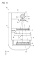
図15は、図14の放射線撮影システムの変形例を示す。 FIG. 15 shows a modification of the radiation imaging system of FIG.
図15に示すマンモグラフィ装置90は、第1の吸収型格子31がX線源11と圧迫板84との間に配設されている点が前述したマンモグラフィ装置80と異なる。
A
このように、被検体(乳房)Bが第1の吸収型格子31と第2の吸収型格子32との間に位置する場合であっても、第2の吸収型格子32の位置に形成される第1の吸収型格子31のG1像は被検体Bにより変調を受ける。したがって、この場合でも、被検体Bに起因して変調されたモアレ縞を含むX線像をX線画像検出器30により検出することができる。すなわち、本マンモグラフィ装置90でも上述した原理で被検体Bの位相コントラスト画像を得ることができる。
Thus, even when the subject (breast) B is located between the first absorption type grating 31 and the second absorption type grating 32, it is formed at the position of the second absorption type grating 32. The G1 image of the first absorption grating 31 is modulated by the subject B. Therefore, even in this case, the
そして、本マンモグラフィ装置90では、第1の吸収型格子31による遮蔽により、線量がほぼ半減したX線が被検体Bに照射されることになるため、被検体Bの被曝量を、前述したマンモグラフィ装置80の場合の約半分に低減することができる。なお、本マンモグラフィ装置90のように、第1の吸収型格子31と第2の吸収型格子32との間に被検体を配置すること、換言すれば、第1の吸収型格子31を被検体の前側(X線源側)に配置することは、上述したX線撮影システム10,60にも適用することが可能である。
In the
図16は、本発明の実施形態を説明するための放射線撮影システムの他の例を示す。 FIG. 16 shows another example of a radiation imaging system for explaining an embodiment of the present invention.
X線撮影システム100は、X線源101のコリメータユニット102に、マルチスリット103を配設した点が、上記第1実施形態のX線撮影システム10と異なる。その他の構成については、前述したX線撮影システム10と同一であるので説明は省略する。
The
前述したX線撮影システム10では、X線源11からX線画像検出器30までの距離を、一般的な病院の撮影室で設定されるような距離(1m〜2m)とした場合に、X線焦点18bの焦点サイズ(一般的に0.1mm〜1mm程度)によるG1像のボケが影響し、位相コントラスト画像の画質の低下をもたらす恐れがある。そこで、X線焦点18bの直後にピンホールを設置して実効的に焦点サイズを小さくすることが考えられるが、実効的な焦点サイズを縮小するためにピンホールの開口面積を小さくすると、X線強度が低下してしまう。本X線撮影システム100においては、この課題を解決するために、X線焦点18bの直後にマルチスリット103を配置する。
In the
マルチスリット103は、第1及び第2の吸収型格子31,32と同様な構成の吸収型格子(第3の吸収型格子)であり、一方向(y方向)に延伸した複数のX線遮蔽部が、第1及び第2の吸収型格子31,32のX線遮蔽部31b,32bと同一方向(x方向)に周期的に配列されている。このマルチスリット103は、X線焦点18bから放射される放射線を部分的に遮蔽することにより、x方向に関する実効的な焦点サイズを縮小して、x方向に多数の点光源(分散光源)を形成することを目的としている。
The
このマルチスリット103の格子ピッチp3は、マルチスリット103から第1の吸収型格子31までの距離をL3として、次式(17)を満たすように設定する必要がある。
式(17)は、マルチスリット103により分散形成された各点光源から射出されたX線の第1の吸収型格子31による投影像(G1像)が、第2の吸収型格子32の位置で一致する(重なり合う)ための幾何学的な条件である。 Expression (17) indicates that the projection image (G1 image) of the X-rays emitted from the point light sources dispersedly formed by the multi-slit 103 by the first absorption type grating 31 is the position of the second absorption type grating 32. This is a geometric condition for matching (overlapping).
また、実質的にマルチスリット103の位置がX線焦点位置となるため、第2の吸収型格子32の格子ピッチp2は、次式(18)の関係を満たすように決定される。
In addition, since the position of the
このように、本X線撮影システム100では、マルチスリット103により形成される複数の点光源に基づくG1像が重ね合わせられることにより、X線強度を低下させずに、位相コントラスト画像の画質を向上させることができる。マルチスリット103は、前述したいずれのX線撮影システムにおいても適用可能である。
As described above, in the present
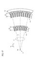
図17は、本発明の実施形態を説明するための放射線撮影システムの他の例に関し、その第1及び第2の格子の構成を示す。 FIG. 17 shows the configuration of the first and second gratings for another example of the radiation imaging system for explaining the embodiment of the present invention.
前述したX線撮影システム10においては、第1及び第2の吸収型格子31,32は、X線遮蔽部31b,32bの周期配列方向が直線状(すなわち、格子面が平面状)となるように構成されているが、これに代えて、図19に示すように、格子面を略凹曲面状に構成した第1及び第2の吸収型格子110,111を用いることもできる。この場合に、検出面が円筒面状のX線画像検出器112を用いることが好ましく、X線画像検出器112の検出面は、X線焦点18bを通りy方向に延びる直線を中心軸とする円筒面状とする。
In the
第1の吸収型格子110は、複数の第1の格子モジュール33を連結して構成されており、第1の格子モジュール33は、X線焦点18bを通りX線遮蔽部35の延伸方向(y方向)に延びる仮想線を中心軸とする円筒面に沿って配列されている。同様に、第2の吸収型格子111もまた、複数の第2の格子モジュール36を連結して構成されており、第2の格子モジュール36は、X線焦点18bを通りX線遮蔽部38の延伸方向(y方向)に延びる仮想線を中心軸とする円筒面に沿って配列されている。
The first absorption type grating 110 is configured by connecting a plurality of first
このように、第1及び第2の吸収型格子110,111を、それぞれ複数の格子モジュールを連結して構成することで、それらの格子面を容易に略凹曲面状に構成することができる。そして、第1及び第2の吸収型格子110,111の格子面を略凹曲面状とすることにより、X線焦点18bから照射されるX線は、被検体Hが存在しない場合、格子面の各部に略垂直に入射することになるため、X線遮蔽部35の厚みh1とX線遮蔽部38の厚みh2との上限の制約が緩和され、上記式(6)及び(7)を考慮する必要がない。
In this way, by configuring the first and second
なお、X線画像検出器112についても、第1及び第2の吸収型格子110,111と同様に、複数の検出器モジュールに分割して構成し、それらの検出器モジュールを円筒面に沿って配列するようにすれば、その検出面を容易に円筒面状とすることができる。
The
上述した各X線撮影システムでは、放射線として一般的なX線を用いる場合について説明したが、本発明に用いられる放射線はX線に限られるものではなく、α線、γ線等のX線以外の放射線を用いることも可能である。 In each X-ray imaging system described above, the case where general X-rays are used as radiation has been described. However, the radiation used in the present invention is not limited to X-rays, but other than X-rays such as α-rays and γ-rays. It is also possible to use other radiation.
以上、説明したように、本明細書には、下記(1)〜(9)の放射線撮影システムが開示されている。 As described above, the following (1) to (9) radiation imaging systems are disclosed in this specification.
(1) 放射線照射野に配置される被写体によって変調を受けた周期パターンを含む放射線画像を取得する撮影部と、前記放射線画像に含まれる前記周期パターンに基づいて前記被写体の位相コントラスト画像を生成する演算処理部と、を備え、前記撮影部は、通過する放射線によって、前記放射線画像に含まれる前記周期パターンの基礎となる周期的強度分布を含む放射線像を形成する一つ以上の格子と、前記放射線像を検出する放射線画像検出器と、を有しており、前記格子及び前記放射線画像検出器の要素のうち少なくとも一つの要素は、複数のモジュールに分割されて構成されており、前記演算処理部は、モジュール分割された前記要素のうち少なくとも一つの要素におけるモジュール間の境界の少なくとも一部に対応させて前記放射線画像を複数の部分放射線画像に区分し、これらの部分放射線画像毎に、前記部分放射線画像に対してフーリエ変換を行って該部分放射線画像の空間周波数スペクトルを取得する変換処理と、前記部分放射線画像に含まれる周期パターンの基本周波数成分を含む空間周波数領域を前記空間周波数スペクトルから分離し、分離された前記空間周波数領域に対して逆フーリエ変換を行って部分位相コントラスト画像を生成する部分位相コントラスト画像生成処理と、を実行し、そして、前記部分位相コントラスト画像生成処理によって生成される複数の部分位相コントラスト画像を結合して前記被写体の位相コントラスト画像を生成する結合処理を実行する、放射線撮影システム。
(2) 上記(1)の放射線撮影システムであって、通過する放射線によって前記周期的強度分布を含む第1の放射線像を形成する第1の格子を備え、前記放射線画像検出器は、前記第1の放射線像を検出する放射線撮影システム。
(3) 上記(2)の放射線撮影システムであって、前記放射線画像検出器は、複数の検出器モジュールに分割されて構成されており、前記演算処理部は、少なくとも前記放射線画像検出器における検出器モジュール間の境界の少なくとも一部に対応させて前記放射線画像を前記複数の部分放射線画像に区分する放射線撮影システム。
(4) 上記(2)又は(3)の放射線撮影システムであって、前記第1の格子は、複数の第1の格子モジュールに分割されて構成されており、前記演算処理部は、少なくとも前記第1の格子における第1の格子モジュール間の境界の少なくとも一部に対応させて前記放射線画像を前記複数の部分放射線画像に区分する放射線撮影システム。
(5) 上記(2)から(4)のいずれか一つの放射線撮影システムであって、前記放射線画像検出器は、放射線を検出して電荷を蓄積する複数の画素のアレイを有し、これらの画素は、前記第1の放射線像の前記周期的強度分布の周期の1/2以下のピッチに配列されており、前記放射線画像に含まれる周期パターンは、前記第1の放射線像の前記周期的強度分布に対応する放射線撮影システム。
(6) 上記(2)から(4)のいずれか一つの放射線撮影システムであって、前記放射線画像検出器は、放射線を検出して電荷を蓄積する複数の画素のアレイを有し、これらの画素は、前記第1の放射線像の前記周期的強度分布の周期との関係でモアレを形成するピッチに配列されており、前記放射線画像に含まれる周期パターンは、前記モアレに対応する放射線撮影システム。
(7) 上記(5)又は(6)の放射線撮影システムであって、前記放射線画像検出器は、前記各画素に蓄積された電荷を読み出す読み出し回路を有し、前記読み出し回路は、半導体基板に形成されている前記放射線撮影システム。
(8) 上記(2)から(4)のいずれか一つの放射線撮影システムであって、前記第1の放射線像をマスキングしてモアレ縞を含む第2の放射線像を形成する第2の格子をさらに備え、前記放射線画像検出器は、前記第1の放射線像を検出するのに替えて、前記第2の放射線像を検出する放射線撮影システム。
(9) 上記(8)の放射線撮影システムであって、前記第2の格子は、複数の第2の格子モジュールに分割されて構成されており、前記演算処理部は、少なくとも前記第2の格子における第2の格子モジュール間の境界の少なくとも一部に対応させて前記放射線画像を前記複数の部分放射線画像に区分する放射線撮影システム。
(1) An imaging unit that acquires a radiographic image including a periodic pattern modulated by a subject arranged in a radiation irradiation field, and generates a phase contrast image of the subject based on the periodic pattern included in the radiographic image An arithmetic processing unit, wherein the imaging unit forms one or more gratings that form a radiation image including a periodic intensity distribution that is a basis of the periodic pattern included in the radiation image by passing radiation; and A radiation image detector for detecting a radiation image, wherein at least one of the lattice and the elements of the radiation image detector is divided into a plurality of modules, and the arithmetic processing The unit is configured to correspond to at least a part of a boundary between modules in at least one of the elements divided into modules. A line image is divided into a plurality of partial radiation images, and for each partial radiation image, a Fourier transform is performed on the partial radiation image to obtain a spatial frequency spectrum of the partial radiation image, and the partial radiation A partial phase contrast that separates a spatial frequency region including a fundamental frequency component of a periodic pattern included in an image from the spatial frequency spectrum, and performs an inverse Fourier transform on the separated spatial frequency region to generate a partial phase contrast image. A radiographic imaging system that executes a combining process of combining a plurality of partial phase contrast images generated by the partial phase contrast image generating process to generate a phase contrast image of the subject. .
(2) The radiation imaging system according to (1), further including a first grating that forms a first radiation image including the periodic intensity distribution by passing radiation, wherein the radiation image detector includes A radiation imaging system for detecting a radiation image of 1.
(3) The radiation imaging system according to (2), wherein the radiation image detector is divided into a plurality of detector modules, and the arithmetic processing unit is at least detected by the radiation image detector. A radiation imaging system that divides the radiation image into the plurality of partial radiation images in correspondence with at least a part of a boundary between the instrument modules.
(4) In the radiation imaging system according to (2) or (3), the first grating is configured by being divided into a plurality of first grating modules, and the arithmetic processing unit includes at least the arithmetic processing unit. A radiation imaging system that divides the radiation image into the plurality of partial radiation images in correspondence with at least a part of a boundary between first grating modules in a first grating.
(5) The radiation imaging system according to any one of (2) to (4), wherein the radiation image detector includes an array of a plurality of pixels that detect radiation and accumulate electric charges, and The pixels are arranged at a pitch of ½ or less of the period of the periodic intensity distribution of the first radiation image, and the periodic pattern included in the radiation image is the periodic pattern of the first radiation image. Radiography system corresponding to intensity distribution.
(6) The radiation imaging system according to any one of (2) to (4), wherein the radiation image detector includes an array of a plurality of pixels that detect radiation and accumulate electric charges. The pixels are arranged in a pitch that forms moire in relation to the period of the periodic intensity distribution of the first radiation image, and the periodic pattern included in the radiation image has a radiation imaging system corresponding to the moire. .
(7) In the radiation imaging system according to (5) or (6), the radiation image detector includes a readout circuit that reads out the electric charges accumulated in the pixels, and the readout circuit is provided on a semiconductor substrate. The said radiography system currently formed.
(8) In the radiation imaging system according to any one of (2) to (4), a second grating that forms a second radiation image including a moire fringe by masking the first radiation image. The radiographic imaging system further includes the radiographic image detector for detecting the second radiographic image instead of detecting the first radiographic image.
(9) In the radiographic system according to (8), the second grating is configured to be divided into a plurality of second grating modules, and the arithmetic processing unit includes at least the second grating. A radiation imaging system that divides the radiation image into the plurality of partial radiation images corresponding to at least a part of a boundary between the second grating modules in FIG.
10 X線撮影システム
11 X線源
12 撮影部
13 コンソール
30 X線画像検出器
31 第1の吸収型格子
32 第2の吸収型格子
40 画素
DESCRIPTION OF
Claims (9)
前記放射線画像に含まれる前記周期パターンに基づいて前記被写体の位相コントラスト画像を生成する演算処理部と、
を備え、
前記撮影部は、通過する放射線によって、前記放射線画像に含まれる前記周期パターンの基礎となる周期的強度分布を含む放射線像を形成する一つ以上の格子と、前記放射線像を検出する放射線画像検出器と、を有しており、
前記格子及び前記放射線画像検出器の要素のうち少なくとも一つの要素は、複数のモジュールに分割されて構成されており、
前記演算処理部は、モジュール分割された前記要素のうち少なくとも一つの要素におけるモジュール間の境界の少なくとも一部に対応させて前記放射線画像を複数の部分放射線画像に区分し、これらの部分放射線画像毎に、前記部分放射線画像に対してフーリエ変換を行って該部分放射線画像の空間周波数スペクトルを取得する変換処理と、前記部分放射線画像に含まれる周期パターンの基本周波数成分を含む空間周波数領域を前記空間周波数スペクトルから分離し、分離された前記空間周波数領域に対して逆フーリエ変換を行って部分位相コントラスト画像を生成する部分位相コントラスト画像生成処理と、を実行し、そして、前記部分位相コントラスト画像生成処理によって生成される複数の部分位相コントラスト画像を結合して前記被写体の位相コントラスト画像を生成する結合処理を実行する、放射線撮影システム。 An imaging unit for acquiring a radiographic image including a periodic pattern modulated by a subject arranged in a radiation irradiation field;
An arithmetic processing unit for generating a phase contrast image of the subject based on the periodic pattern included in the radiation image;
With
The imaging unit includes one or more gratings that form a radiation image including a periodic intensity distribution that is a basis of the periodic pattern included in the radiation image, and a radiation image detection that detects the radiation image. And
At least one element of the grating and the elements of the radiation image detector is configured by being divided into a plurality of modules.
The arithmetic processing unit divides the radiographic image into a plurality of partial radiographic images corresponding to at least a part of a boundary between modules in at least one of the elements divided into modules, and each of the partial radiographic images A spatial frequency region including a fundamental frequency component of a periodic pattern included in the partial radiation image, and a transformation process for performing a Fourier transform on the partial radiation image to obtain a spatial frequency spectrum of the partial radiation image. Performing a partial phase contrast image generation process for generating a partial phase contrast image by performing an inverse Fourier transform on the separated spatial frequency domain to generate a partial phase contrast image, and performing the partial phase contrast image generation process Combining the plurality of partial phase contrast images generated by Executing a binding process to generate a phase contrast image of the body, a radiation imaging system.
通過する放射線によって前記周期的強度分布を含む第1の放射線像を形成する第1の格子を備え、
前記放射線画像検出器は、前記第1の放射線像を検出する放射線撮影システム。 The radiation imaging system according to claim 1,
A first grating for forming a first radiation image including the periodic intensity distribution by passing radiation;
The radiation image detector is a radiation imaging system that detects the first radiation image.
前記放射線画像検出器は、複数の検出器モジュールに分割されて構成されており、
前記演算処理部は、少なくとも前記放射線画像検出器における検出器モジュール間の境界の少なくとも一部に対応させて前記放射線画像を前記複数の部分放射線画像に区分する放射線撮影システム。 The radiographic system according to claim 2,
The radiation image detector is configured by being divided into a plurality of detector modules,
The radiation processing system in which the arithmetic processing unit classifies the radiation image into the plurality of partial radiation images in correspondence with at least a part of a boundary between detector modules in the radiation image detector.
前記第1の格子は、複数の第1の格子モジュールに分割されて構成されており、
前記演算処理部は、少なくとも前記第1の格子における第1の格子モジュール間の境界の少なくとも一部に対応させて前記放射線画像を前記複数の部分放射線画像に区分する放射線撮影システム。 The radiographic system according to claim 2 or 3,
The first lattice is divided into a plurality of first lattice modules,
The arithmetic processing unit divides the radiographic image into the plurality of partial radiographic images in correspondence with at least a part of a boundary between first grid modules in the first grid.
前記放射線画像検出器は、放射線を検出して電荷を蓄積する複数の画素のアレイを有し、これらの画素は、前記第1の放射線像の前記周期的強度分布の周期の1/2以下のピッチに配列されており、
前記放射線画像に含まれる周期パターンは、前記第1の放射線像の前記周期的強度分布に対応する放射線撮影システム。 The radiographic system according to any one of claims 2 to 4,
The radiation image detector has an array of a plurality of pixels that detect radiation and accumulate electric charge, and these pixels are equal to or less than ½ of the period of the periodic intensity distribution of the first radiation image. Arranged on the pitch,
The periodic pattern included in the radiation image is a radiation imaging system corresponding to the periodic intensity distribution of the first radiation image.
前記放射線画像検出器は、放射線を検出して電荷を蓄積する複数の画素のアレイを有し、これらの画素は、前記第1の放射線像の前記周期的強度分布の周期との関係でモアレを形成するピッチに配列されており、
前記放射線画像に含まれる周期パターンは、前記モアレに対応する放射線撮影システム。 The radiographic system according to any one of claims 2 to 4,
The radiation image detector has an array of a plurality of pixels that detect radiation and accumulate electric charges, and these pixels are moire in relation to the period of the periodic intensity distribution of the first radiation image. Arranged in the pitch to be formed,
The periodic pattern included in the radiation image is a radiation imaging system corresponding to the moire.
前記放射線画像検出器は、前記各画素に蓄積された電荷を読み出す読み出し回路を有し、前記読み出し回路は、半導体基板に形成されている前記放射線撮影システム。 The radiographic system according to claim 5 or 6,
The radiation image detector includes a readout circuit that reads out charges accumulated in the pixels, and the readout circuit is formed on a semiconductor substrate.
前記第1の放射線像をマスキングしてモアレ縞を含む第2の放射線像を形成する第2の格子をさらに備え、
前記放射線画像検出器は、前記第1の放射線像を検出するのに替えて、前記第2の放射線像を検出する放射線撮影システム。 The radiographic system according to any one of claims 2 to 4,
A second grating for masking the first radiation image to form a second radiation image including moire fringes;
The radiographic image detector detects the second radiographic image instead of detecting the first radiographic image.
前記第2の格子は、複数の第2の格子モジュールに分割されて構成されており、
前記演算処理部は、少なくとも前記第2の格子における第2の格子モジュール間の境界の少なくとも一部に対応させて前記放射線画像を前記複数の部分放射線画像に区分する放射線撮影システム。 The radiation imaging system according to claim 8,
The second grating is configured by being divided into a plurality of second grating modules,
The radiographic system that divides the radiographic image into the plurality of partial radiographic images in correspondence with at least a part of a boundary between second grid modules in the second grid.
Priority Applications (2)
| Application Number | Priority Date | Filing Date | Title |
|---|---|---|---|
| JP2011130709A JP2014155509A (en) | 2011-06-10 | 2011-06-10 | Radiographic system |
| PCT/JP2012/064128 WO2012169427A1 (en) | 2011-06-10 | 2012-05-31 | Radiography system |
Applications Claiming Priority (1)
| Application Number | Priority Date | Filing Date | Title |
|---|---|---|---|
| JP2011130709A JP2014155509A (en) | 2011-06-10 | 2011-06-10 | Radiographic system |
Publications (1)
| Publication Number | Publication Date |
|---|---|
| JP2014155509A true JP2014155509A (en) | 2014-08-28 |
Family
ID=47295993
Family Applications (1)
| Application Number | Title | Priority Date | Filing Date |
|---|---|---|---|
| JP2011130709A Withdrawn JP2014155509A (en) | 2011-06-10 | 2011-06-10 | Radiographic system |
Country Status (2)
| Country | Link |
|---|---|
| JP (1) | JP2014155509A (en) |
| WO (1) | WO2012169427A1 (en) |
Cited By (4)
| Publication number | Priority date | Publication date | Assignee | Title |
|---|---|---|---|---|
| KR101636438B1 (en) * | 2015-03-18 | 2016-07-05 | 제이피아이헬스케어 주식회사 | Phase-contrast X-ray imaging(PCXI) method using a single grid and the apparatus thereof |
| JP2017538471A (en) * | 2014-11-24 | 2017-12-28 | コーニンクレッカ フィリップス エヌ ヴェKoninklijke Philips N.V. | Detector and imaging system for X-ray phase contrast tomosynthesis imaging |
| WO2020039654A1 (en) * | 2018-08-22 | 2020-02-27 | 株式会社島津製作所 | X-ray phase imaging device |
| CN107440729B (en) * | 2016-04-19 | 2021-01-01 | 西门子保健有限责任公司 | Method for correcting X-ray images, X-ray device and electronically readable data carrier |
Family Cites Families (4)
| Publication number | Priority date | Publication date | Assignee | Title |
|---|---|---|---|---|
| JP2002159482A (en) * | 2000-11-24 | 2002-06-04 | Konica Corp | Method of phase-contrast x-ray imaging and phase- contrast x-ray imaging apparatus |
| DE102006017290B4 (en) * | 2006-02-01 | 2017-06-22 | Siemens Healthcare Gmbh | Focus / detector system of an X-ray apparatus, X-ray system and method for producing phase-contrast images |
| DE102006015358B4 (en) * | 2006-02-01 | 2019-08-22 | Paul Scherer Institut | Focus / detector system of an X-ray apparatus for producing phase-contrast images, associated X-ray system and storage medium and method for producing tomographic images |
| EP2343537B1 (en) * | 2008-10-29 | 2019-04-10 | Canon Kabushiki Kaisha | X-ray imaging device and x-ray imaging method |
-
2011
- 2011-06-10 JP JP2011130709A patent/JP2014155509A/en not_active Withdrawn
-
2012
- 2012-05-31 WO PCT/JP2012/064128 patent/WO2012169427A1/en not_active Ceased
Cited By (4)
| Publication number | Priority date | Publication date | Assignee | Title |
|---|---|---|---|---|
| JP2017538471A (en) * | 2014-11-24 | 2017-12-28 | コーニンクレッカ フィリップス エヌ ヴェKoninklijke Philips N.V. | Detector and imaging system for X-ray phase contrast tomosynthesis imaging |
| KR101636438B1 (en) * | 2015-03-18 | 2016-07-05 | 제이피아이헬스케어 주식회사 | Phase-contrast X-ray imaging(PCXI) method using a single grid and the apparatus thereof |
| CN107440729B (en) * | 2016-04-19 | 2021-01-01 | 西门子保健有限责任公司 | Method for correcting X-ray images, X-ray device and electronically readable data carrier |
| WO2020039654A1 (en) * | 2018-08-22 | 2020-02-27 | 株式会社島津製作所 | X-ray phase imaging device |
Also Published As
| Publication number | Publication date |
|---|---|
| WO2012169427A1 (en) | 2012-12-13 |
Similar Documents
| Publication | Publication Date | Title |
|---|---|---|
| JP5331940B2 (en) | Radiation imaging system and radiation image generation method | |
| JP5731214B2 (en) | Radiation imaging system and image processing method thereof | |
| JP5548085B2 (en) | Adjustment method of diffraction grating | |
| JP5783987B2 (en) | Radiography equipment | |
| JP2012090945A (en) | Radiation detection device, radiographic apparatus, and radiographic system | |
| JP2011218147A (en) | Radiographic system | |
| JP2012200567A (en) | Radiographic system and radiographic method | |
| JP2012090944A (en) | Radiographic system and radiographic method | |
| JP2011224329A (en) | Radiation imaging system and method | |
| JP2012120715A (en) | Radiological image detection apparatus, radiographic apparatus and radiographic system | |
| JP2012095865A (en) | Radiographic apparatus and radiographic system | |
| JP2011224330A (en) | Radiation imaging system and offset correction method therefor | |
| WO2012169426A1 (en) | Radiography system | |
| JP2011206490A (en) | Radiographic system and radiographic method | |
| JP2014155509A (en) | Radiographic system | |
| JP2012120650A (en) | Radiographic system and method for generating radiation phase contrast image | |
| JP2012125423A (en) | Radiation image detection apparatus, radiographic imaging apparatus, and radiographic imaging system | |
| WO2013047011A1 (en) | Radiographic image detector, method of manufacturing same, and radiography system employing radiographic image detector | |
| JP5610480B2 (en) | Radiation image processing apparatus and method | |
| WO2012056992A1 (en) | Radiograph detection device, radiography device, radiography system | |
| JP2013150780A (en) | Radiographic apparatus and radiographic method | |
| JP2014132913A (en) | Radiation image-capturing system, and radiation image-capturing method | |
| JP2012228369A (en) | Radiographic system, and radiographic method | |
| WO2012057045A1 (en) | X-ray imaging device, x-ray imaging system | |
| WO2012057046A1 (en) | Radiography device and radiography system |
Legal Events
| Date | Code | Title | Description |
|---|---|---|---|
| A300 | Application deemed to be withdrawn because no request for examination was validly filed |
Free format text: JAPANESE INTERMEDIATE CODE: A300 Effective date: 20140902 |