JP2014165152A - 電磁継電器 - Google Patents
電磁継電器 Download PDFInfo
- Publication number
- JP2014165152A JP2014165152A JP2013037803A JP2013037803A JP2014165152A JP 2014165152 A JP2014165152 A JP 2014165152A JP 2013037803 A JP2013037803 A JP 2013037803A JP 2013037803 A JP2013037803 A JP 2013037803A JP 2014165152 A JP2014165152 A JP 2014165152A
- Authority
- JP
- Japan
- Prior art keywords
- electrode plate
- movable
- fixed
- plate
- electromagnetic relay
- Prior art date
- Legal status (The legal status is an assumption and is not a legal conclusion. Google has not performed a legal analysis and makes no representation as to the accuracy of the status listed.)
- Pending
Links
Images









Classifications
-
- H—ELECTRICITY
- H01—ELECTRIC ELEMENTS
- H01H—ELECTRIC SWITCHES; RELAYS; SELECTORS; EMERGENCY PROTECTIVE DEVICES
- H01H50/00—Details of electromagnetic relays
- H01H50/54—Contact arrangements
- H01H50/60—Contact arrangements moving contact being rigidly combined with movable part of magnetic circuit
-
- H—ELECTRICITY
- H01—ELECTRIC ELEMENTS
- H01H—ELECTRIC SWITCHES; RELAYS; SELECTORS; EMERGENCY PROTECTIVE DEVICES
- H01H50/00—Details of electromagnetic relays
- H01H50/02—Bases; Casings; Covers
- H01H50/026—Details concerning isolation between driving and switching circuit
-
- H—ELECTRICITY
- H01—ELECTRIC ELEMENTS
- H01H—ELECTRIC SWITCHES; RELAYS; SELECTORS; EMERGENCY PROTECTIVE DEVICES
- H01H50/00—Details of electromagnetic relays
- H01H50/02—Bases; Casings; Covers
- H01H50/04—Mounting complete relay or separate parts of relay on a base or inside a case
- H01H50/047—Details concerning mounting a relays
-
- H—ELECTRICITY
- H01—ELECTRIC ELEMENTS
- H01H—ELECTRIC SWITCHES; RELAYS; SELECTORS; EMERGENCY PROTECTIVE DEVICES
- H01H50/00—Details of electromagnetic relays
- H01H50/54—Contact arrangements
- H01H50/56—Contact spring sets
-
- H—ELECTRICITY
- H01—ELECTRIC ELEMENTS
- H01H—ELECTRIC SWITCHES; RELAYS; SELECTORS; EMERGENCY PROTECTIVE DEVICES
- H01H50/00—Details of electromagnetic relays
- H01H50/54—Contact arrangements
- H01H50/56—Contact spring sets
- H01H50/58—Driving arrangements structurally associated therewith; Mounting of driving arrangements on armature
-
- H—ELECTRICITY
- H01—ELECTRIC ELEMENTS
- H01H—ELECTRIC SWITCHES; RELAYS; SELECTORS; EMERGENCY PROTECTIVE DEVICES
- H01H50/00—Details of electromagnetic relays
- H01H50/64—Driving arrangements between movable part of magnetic circuit and contact
- H01H50/641—Driving arrangements between movable part of magnetic circuit and contact intermediate part performing a rectilinear movement
- H01H50/642—Driving arrangements between movable part of magnetic circuit and contact intermediate part performing a rectilinear movement intermediate part being generally a slide plate, e.g. a card
-
- H—ELECTRICITY
- H01—ELECTRIC ELEMENTS
- H01H—ELECTRIC SWITCHES; RELAYS; SELECTORS; EMERGENCY PROTECTIVE DEVICES
- H01H50/00—Details of electromagnetic relays
- H01H50/64—Driving arrangements between movable part of magnetic circuit and contact
- H01H50/647—Driving arrangements between movable part of magnetic circuit and contact intermediate part comprising interlocking means for different contact pairs
-
- H—ELECTRICITY
- H01—ELECTRIC ELEMENTS
- H01H—ELECTRIC SWITCHES; RELAYS; SELECTORS; EMERGENCY PROTECTIVE DEVICES
- H01H51/00—Electromagnetic relays
- H01H51/02—Non-polarised relays
- H01H51/04—Non-polarised relays with single armature; with single set of ganged armatures
- H01H51/06—Armature is movable between two limit positions of rest and is moved in one direction due to energisation of an electromagnet and after the electromagnet is de-energised is returned by energy stored during the movement in the first direction, e.g. by using a spring, by using a permanent magnet, by gravity
-
- H—ELECTRICITY
- H01—ELECTRIC ELEMENTS
- H01H—ELECTRIC SWITCHES; RELAYS; SELECTORS; EMERGENCY PROTECTIVE DEVICES
- H01H2205/00—Movable contacts
- H01H2205/002—Movable contacts fixed to operating part
Landscapes
- Physics & Mathematics (AREA)
- Electromagnetism (AREA)
- Switch Cases, Indication, And Locking (AREA)
- Contacts (AREA)
Abstract
【解決手段】電磁継電器は、電磁石12を内部に配置するケース9と、接極子16と、板状部18bを有し、接極子16の動作により可動接点が移動する可動電極板18と、板状部17bを有する固定電極板17とを備える。可動電極板18の板状部18bは、可動接点が配置されている可動接点配置部を有し、固定電極板17の板状部17bは、固定接点17aが配置されている固定接点配置部を有し、可動接点配置部の幅方向および固定接点配置部の幅方向が傾斜している。
【選択図】図1
Description
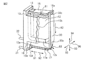
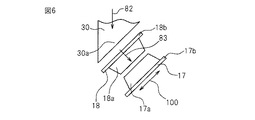
図1から図14を参照して、実施の形態1における電磁継電器について説明する。図1は、本実施の形態の第1の電磁継電器の分解斜視図である。図2は、本実施の形態の第1の電磁継電器のケースを取り外したときの概略斜視図である。図3は、本実施の形態の第1の電磁継電器の概略断面図である。
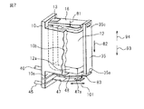
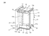
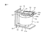
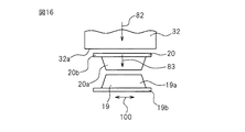
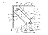
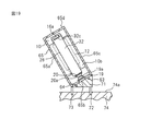
図15から図19を参照して、実施の形態2における電磁継電器について説明する。図15は、本実施の形態の第1の電磁継電器のケースを取り外したときの概略斜視図である。図16は、本実施の形態の第1の電磁継電器の可動電極板、固定電極板およびカードの部分の拡大概略図である。図17は、本実施の形態の第1の電磁継電器のケースの一部を切断したときの概略断面図である。本実施の形態の第1の電磁継電器は、ベース部材10、電磁石12、カード32および可動電極板20を含む本体部27がケース61の内部で傾斜して配置されている。
9a〜9e,61a〜61d 外面
10 ベース部材
10f 固定部
12,51 電磁石
16,53 接極子
17,19,23,25,54,56 固定電極板
17a,19a,23a,25a,54a,56a 固定接点
17b,19b,23b,25b,54b,56b 板状部
17c 固定接点配置部
18,20,24,26,55,57 可動電極板
18a,20a,24a,26a,55a,57a 可動接点
18b,20b,24b,26b,55b,57b 板状部
18c 可動接点配置部
27,28 本体部
30〜34 カード
30a,31a,33a,34a 押圧部
71 ソケット
74 基板
74a 装着面
Claims (7)
- コイルを含む電磁石と、
前記コイルを励磁すると前記電磁石に引き寄せられる接極子と、
板状部および可動接点を有し、前記接極子の動作により前記可動接点が移動する可動電極板と、
前記可動電極板に対向し、板状部および固定接点を有する固定電極板とを備え、
前記可動電極板の板状部は、前記可動接点が配置されている可動接点配置部を有し、前記固定電極板の板状部は、前記固定接点が配置されている固定接点配置部を有し、前記可動接点配置部の幅方向および前記固定接点配置部の幅方向が傾斜していることを特徴とする、電磁継電器。 - 前記接極子に連結され、前記接極子の動作によって移動する移動部材を更に備え、
前記可動接点配置部の幅方向および前記固定接点配置部の幅方向は、前記移動部材の移動方向に対して傾斜している、請求項1に記載の電磁継電器。 - 前記電磁石を内部に配置するケースを更に備え、
前記可動接点配置部の幅方向および前記固定接点配置部の幅方向は、前記ケースの少なくとも一つの外面に対して傾斜している、請求項1に記載の電磁継電器。 - 前記移動部材は、前記可動電極板を押圧する押圧部を有し、
前記押圧部は、前記可動電極板に接触する端面が前記可動電極板の板状部の表面とほぼ平行になる形状を有する、請求項2に記載の電磁継電器。 - 前記可動電極板は、前記接極子に固定され、
前記可動接点配置部の幅方向および前記固定接点配置部の幅方向は、前記接極子が前記電磁石に引き寄せられる方向に対して傾斜している、請求項1に記載の電磁継電器。 - コイルを含む電磁石と、
前記コイルを励磁すると前記電磁石に引き寄せられる接極子と、
板状部および可動接点を有し、前記接極子の動作により可動接点が移動する第1の可動電極板と、
前記第1の可動電極板と電気的に接続され、板状部および可動接点を有し、前記接極子の動作により可動接点が移動する第2の可動電極板と、
前記第1の可動電極板に対向し、板状部および固定接点を有する第1の固定電極板と、
前記第1の固定電極板と電気的に接続され、前記第2の可動電極板に対向し、板状部および固定接点を有する第2の固定電極板とを備え、
前記第1の可動電極板の板状部は、可動接点が配置されている第1の可動接点配置部を有し、
前記第2の可動電極板の板状部は、可動接点が配置されている第2の可動接点配置部を有し、
前記第1の可動接点配置部の面の延びる方向と、前記第2の可動接点配置部の面の延びる方向とが交差していることを特徴とする、電磁継電器。 - コイルを有する電磁石を含む本体部と、
前記本体部が内部に固定されているケースとを備え、
前記本体部は、前記コイルを励磁すると前記電磁石に引き寄せられる接極子と、板状部および可動接点を有し、前記接極子の動作により前記可動接点が移動する可動電極板と、前記可動電極板に対向し、板状部および固定接点を有する固定電極板とを含み、
前記可動電極板の板状部は、前記可動接点が配置されている可動接点配置部を有し、
前記固定電極板の板状部は、前記固定接点が配置されている固定接点配置部を有し、
前記本体部は、被装着物に電磁継電器を装着したときに前記被装着物の装着面に対して傾斜し、前記可動接点配置部の幅方向および前記固定接点配置部の幅方向は、前記装着面に対して傾斜していることを特徴とする、電磁継電器。
Priority Applications (3)
| Application Number | Priority Date | Filing Date | Title |
|---|---|---|---|
| JP2013037803A JP2014165152A (ja) | 2013-02-27 | 2013-02-27 | 電磁継電器 |
| US14/099,161 US9202653B2 (en) | 2013-02-27 | 2013-12-06 | Electromagnetic relay |
| US14/937,495 US20160086755A1 (en) | 2013-02-27 | 2015-11-10 | Electromagnetic relay |
Applications Claiming Priority (1)
| Application Number | Priority Date | Filing Date | Title |
|---|---|---|---|
| JP2013037803A JP2014165152A (ja) | 2013-02-27 | 2013-02-27 | 電磁継電器 |
Publications (2)
| Publication Number | Publication Date |
|---|---|
| JP2014165152A true JP2014165152A (ja) | 2014-09-08 |
| JP2014165152A5 JP2014165152A5 (ja) | 2016-02-25 |
Family
ID=51387547
Family Applications (1)
| Application Number | Title | Priority Date | Filing Date |
|---|---|---|---|
| JP2013037803A Pending JP2014165152A (ja) | 2013-02-27 | 2013-02-27 | 電磁継電器 |
Country Status (2)
| Country | Link |
|---|---|
| US (2) | US9202653B2 (ja) |
| JP (1) | JP2014165152A (ja) |
Cited By (1)
| Publication number | Priority date | Publication date | Assignee | Title |
|---|---|---|---|---|
| WO2018235517A1 (ja) * | 2017-06-22 | 2018-12-27 | オムロン株式会社 | スイッチ |
Families Citing this family (7)
| Publication number | Priority date | Publication date | Assignee | Title |
|---|---|---|---|---|
| JP6245557B2 (ja) * | 2013-12-13 | 2017-12-13 | パナソニックIpマネジメント株式会社 | 電磁リレー |
| JP2017139166A (ja) * | 2016-02-04 | 2017-08-10 | 富士通コンポーネント株式会社 | 電磁継電器 |
| JP2018006209A (ja) * | 2016-07-05 | 2018-01-11 | 富士通コンポーネント株式会社 | 電磁継電器 |
| JP6966889B2 (ja) * | 2017-07-28 | 2021-11-17 | 富士通コンポーネント株式会社 | 電磁継電器ユニット |
| EP4645360A3 (en) * | 2020-04-30 | 2026-01-21 | Xiamen Hongfa Electric Power Controls Co., Ltd. | High-voltage dc relay |
| DE102021106112A1 (de) * | 2021-03-12 | 2022-09-15 | Tdk Electronics Ag | Gehäuse für elektromechanische Komponente |
| DE102021106091A1 (de) | 2021-03-12 | 2022-09-15 | Tdk Electronics Ag | Gehäuseanordnung |
Citations (3)
| Publication number | Priority date | Publication date | Assignee | Title |
|---|---|---|---|---|
| JPS55111142U (ja) * | 1979-01-29 | 1980-08-05 | ||
| JP2011081956A (ja) * | 2009-10-05 | 2011-04-21 | Fujitsu Component Ltd | 電磁継電器 |
| JP2012256453A (ja) * | 2011-06-07 | 2012-12-27 | Fujitsu Component Ltd | 電磁継電器 |
Family Cites Families (56)
| Publication number | Priority date | Publication date | Assignee | Title |
|---|---|---|---|---|
| DE7909135U1 (de) * | 1979-03-30 | 1979-07-05 | Siemens Ag, 1000 Berlin Und 8000 Muenchen | Elektromagnetisches Relais für hohe Schaltleistungen |
| DE2912800C2 (de) * | 1979-03-30 | 1985-04-25 | Siemens AG, 1000 Berlin und 8000 München | Elektromagnetisches Relais für hohe Schaltleistungen |
| CA1162218A (en) * | 1981-04-06 | 1984-02-14 | Sds Elektro Gmbh | Electromagnetic relay |
| DE3120117C2 (de) * | 1981-05-20 | 1984-10-31 | Siemens AG, 1000 Berlin und 8000 München | Magnetsystem für ein Relais |
| US4420733A (en) * | 1982-03-25 | 1983-12-13 | Amf Incorporated | Miniaturized electromagnetic relay |
| DE8438436U1 (de) * | 1984-04-18 | 1987-10-22 | Hengstler Bauelemente GmbH, 7209 Wehingen | Kleinstrelais |
| US4688010A (en) * | 1984-12-22 | 1987-08-18 | Matsushita Electric Works, Ltd. | Electromagnetic relay |
| US4656733A (en) * | 1985-09-03 | 1987-04-14 | Omron Tateisi Electronics Co. | Method of manufacture of base assembly for an electromagnetic relay |
| US4740769A (en) * | 1986-06-23 | 1988-04-26 | Siemens Aktiengesellschaft | Electromagnetic relay |
| JPS63149039U (ja) * | 1987-03-20 | 1988-09-30 | ||
| US4761627A (en) * | 1987-09-17 | 1988-08-02 | Potter And Brumfield Inc. | Electromagnetic relay including a rotatable armature mount |
| US4758809A (en) * | 1987-09-17 | 1988-07-19 | Potter And Brumfield Inc. | Electromagnetic relay having a multifunction retaining spring |
| US4792776A (en) * | 1987-09-24 | 1988-12-20 | Siemens Aktiengesellschaft | Miniaturized electromagnetic relay for switching high voltages |
| JP2797261B2 (ja) | 1988-03-28 | 1998-09-17 | 松下電工株式会社 | 電気開閉装置 |
| EP0372554A3 (en) * | 1988-12-09 | 1992-04-08 | OMRON Corporation | Electromagnetic relay |
| JPH0346728A (ja) * | 1989-07-13 | 1991-02-28 | Omron Corp | 電磁継電器 |
| JPH0458933A (ja) | 1990-06-28 | 1992-02-25 | Asahi Optical Co Ltd | 内視鏡の湾曲装置 |
| JPH0469836U (ja) * | 1990-10-26 | 1992-06-19 | ||
| EP0501070B2 (en) * | 1991-02-27 | 2003-05-14 | Takamisawa Electric Co., Ltd. | Small sized electromagnetic relay |
| US5289144A (en) * | 1992-08-21 | 1994-02-22 | Potter & Brumfield, Inc. | Electromagnetic relay and method for assembling the same |
| JPH07254340A (ja) * | 1994-03-15 | 1995-10-03 | Omron Corp | 電磁継電器 |
| IT233985Y1 (it) * | 1994-07-29 | 2000-02-16 | Gavazzi Carlo Electromatic | Rele' elettromagnetico pluricontatto miniatura per usi industriali |
| US5525948A (en) * | 1994-12-02 | 1996-06-11 | Poulsen; Peder U. | Manually operated, electromagnetically resettable safety switch |
| JP3847784B2 (ja) * | 1995-03-21 | 2006-11-22 | タイコ・エレクトロニクス・ロジスティックス・アクチエンゲゼルシャフト | 電磁リレー |
| EP0768694B1 (de) * | 1995-10-09 | 2002-05-08 | Tyco Electronics Logistics AG | Elektromagnetisches Relais und Verfahren zu dessen Herstellung |
| DE19602643A1 (de) * | 1996-01-25 | 1997-07-31 | Siemens Ag | Elektromagnetisches Relais in schmaler Bauweise und Verfahren zu dessen Herstellung |
| DE19606884C1 (de) * | 1996-02-23 | 1997-04-30 | Schrack Components Ag | Elektromagnetisches Relais |
| ID22892A (id) * | 1997-05-05 | 1999-12-16 | Eh Schrack Components Aktieges | Relai elektromagnetik |
| DE19727990C1 (de) * | 1997-07-01 | 1998-11-19 | Schrack Components Ag | Elektromagnetisches Relais mit Handbetätigungsorgan |
| DE19727991C1 (de) * | 1997-07-01 | 1998-11-19 | Schrack Components Ag | Elektromagnetisches Relais |
| US6211761B1 (en) * | 1997-09-10 | 2001-04-03 | Takamisawa Electric Co., Ltd. | Electromagnetic relay, joining structure for hinge spring and yoke in the electromagnetic relay, and flux penetration preventing structure |
| DE69931586T2 (de) * | 1998-12-07 | 2007-05-31 | Matsushita Electric Works, Ltd., Kadoma | Elektromagnetisches Relais |
| JP4085513B2 (ja) * | 1999-04-28 | 2008-05-14 | オムロン株式会社 | 電気機器の封止構造 |
| JP4212248B2 (ja) * | 2001-02-09 | 2009-01-21 | 富士通コンポーネント株式会社 | 電磁継電器 |
| DE10209810B4 (de) * | 2001-03-09 | 2006-11-16 | Omron Corporation | Relais |
| JP4334158B2 (ja) * | 2001-03-26 | 2009-09-30 | 富士通コンポーネント株式会社 | 電磁継電器 |
| JP3870049B2 (ja) * | 2001-08-17 | 2007-01-17 | Necトーキン株式会社 | 電磁継電装置 |
| JP4168733B2 (ja) * | 2002-11-12 | 2008-10-22 | オムロン株式会社 | 電磁継電器 |
| US7046107B2 (en) * | 2003-02-28 | 2006-05-16 | Matsushita Electric Works, Ltd. | Contact device |
| JP3989928B2 (ja) * | 2004-11-02 | 2007-10-10 | ウチヤ・サーモスタット株式会社 | 電磁リレー |
| DE102004060370A1 (de) * | 2004-12-15 | 2006-07-06 | Tyco Electronics Austria Gmbh | Elektromagnetisches Relais |
| JP4810937B2 (ja) * | 2005-09-06 | 2011-11-09 | オムロン株式会社 | 開閉装置 |
| JP4742954B2 (ja) * | 2006-03-31 | 2011-08-10 | オムロン株式会社 | 電磁継電器 |
| JP2008053152A (ja) * | 2006-08-28 | 2008-03-06 | Omron Corp | 静音型電磁継電器 |
| US7477119B2 (en) * | 2007-03-02 | 2009-01-13 | Good Sky Electric Co., Ltd. | Electromagnetic relay |
| JP4803206B2 (ja) * | 2008-04-24 | 2011-10-26 | パナソニック電工株式会社 | リレー用電磁石 |
| JP5004244B2 (ja) * | 2008-05-30 | 2012-08-22 | Necトーキン株式会社 | 電磁継電器 |
| JP5222669B2 (ja) * | 2008-09-16 | 2013-06-26 | 富士通コンポーネント株式会社 | 電磁継電器 |
| JP2010113842A (ja) * | 2008-11-04 | 2010-05-20 | Fujitsu Component Ltd | 電磁継電器 |
| CN102103942B (zh) * | 2009-12-17 | 2013-06-05 | 厦门宏发电声股份有限公司 | 一种继电器的衔铁与推动机构之间的连接结构 |
| JP5566172B2 (ja) * | 2010-04-16 | 2014-08-06 | 富士通コンポーネント株式会社 | 電磁継電器 |
| EP2447977A1 (de) * | 2010-10-29 | 2012-05-02 | Gruner AG | Relais mit einer in eine Drehankerwippe integrierten Kontaktbrücke |
| DE102010063229A1 (de) * | 2010-12-16 | 2012-06-21 | Tyco Electronics Austria Gmbh | Relais mit verbesserter Kontaktfeder |
| JP5807174B2 (ja) * | 2011-03-23 | 2015-11-10 | パナソニックIpマネジメント株式会社 | 電磁リレー |
| JP5864960B2 (ja) * | 2011-09-01 | 2016-02-17 | 富士通コンポーネント株式会社 | 電磁継電器 |
| JP5992721B2 (ja) * | 2012-04-27 | 2016-09-14 | 富士通コンポーネント株式会社 | 電磁継電器 |
-
2013
- 2013-02-27 JP JP2013037803A patent/JP2014165152A/ja active Pending
- 2013-12-06 US US14/099,161 patent/US9202653B2/en not_active Expired - Fee Related
-
2015
- 2015-11-10 US US14/937,495 patent/US20160086755A1/en not_active Abandoned
Patent Citations (3)
| Publication number | Priority date | Publication date | Assignee | Title |
|---|---|---|---|---|
| JPS55111142U (ja) * | 1979-01-29 | 1980-08-05 | ||
| JP2011081956A (ja) * | 2009-10-05 | 2011-04-21 | Fujitsu Component Ltd | 電磁継電器 |
| JP2012256453A (ja) * | 2011-06-07 | 2012-12-27 | Fujitsu Component Ltd | 電磁継電器 |
Cited By (3)
| Publication number | Priority date | Publication date | Assignee | Title |
|---|---|---|---|---|
| WO2018235517A1 (ja) * | 2017-06-22 | 2018-12-27 | オムロン株式会社 | スイッチ |
| CN110651346A (zh) * | 2017-06-22 | 2020-01-03 | 欧姆龙株式会社 | 开关 |
| CN110651346B (zh) * | 2017-06-22 | 2022-05-10 | 欧姆龙株式会社 | 开关 |
Also Published As
| Publication number | Publication date |
|---|---|
| US20160086755A1 (en) | 2016-03-24 |
| US9202653B2 (en) | 2015-12-01 |
| US20140240065A1 (en) | 2014-08-28 |
Similar Documents
| Publication | Publication Date | Title |
|---|---|---|
| CN103928266B (zh) | 电磁继电器 | |
| US9202653B2 (en) | Electromagnetic relay | |
| US20170288524A1 (en) | linear motor | |
| US9064665B2 (en) | Electromagnetic relay | |
| CN102891040A (zh) | 继电器 | |
| CN105097363B (zh) | 触点装置 | |
| EP2919252B1 (en) | Electromagnetic relay | |
| JP6715473B2 (ja) | 可動子及びこれを用いた接点装置 | |
| US9406469B2 (en) | Electromagnetic relay having a movable contact and a fixed contact and method for manufacturing the same | |
| JP6948613B2 (ja) | 接点装置、及び電磁継電器 | |
| CN117174534A (zh) | 引出结构及磁保持继电器 | |
| CA2880067A1 (en) | Electromagnetic relay | |
| JP5807174B2 (ja) | 電磁リレー | |
| JP6897409B2 (ja) | 電磁継電器 | |
| CN105575731A (zh) | 电磁接触器的交叉开关结构 | |
| JP5701110B2 (ja) | 電磁継電器 | |
| JP7716708B2 (ja) | 電磁継電器 | |
| JP4363462B2 (ja) | 高周波リレー | |
| JP2013196923A (ja) | 電磁継電器およびその接点構造 | |
| CN223771051U (zh) | 可动构件及继电器 | |
| JP5525672B2 (ja) | 電磁リレーのヨークの構造 | |
| CN209561301U (zh) | 一种防止静端子变形的继电器 | |
| JP6830259B2 (ja) | 電磁継電器 | |
| JP2017041444A (ja) | 有極リレー | |
| JP2017139194A (ja) | 電磁継電器 |
Legal Events
| Date | Code | Title | Description |
|---|---|---|---|
| A521 | Request for written amendment filed |
Free format text: JAPANESE INTERMEDIATE CODE: A523 Effective date: 20160105 |
|
| A621 | Written request for application examination |
Free format text: JAPANESE INTERMEDIATE CODE: A621 Effective date: 20160105 |
|
| A977 | Report on retrieval |
Free format text: JAPANESE INTERMEDIATE CODE: A971007 Effective date: 20160928 |
|
| A131 | Notification of reasons for refusal |
Free format text: JAPANESE INTERMEDIATE CODE: A131 Effective date: 20161018 |
|
| A02 | Decision of refusal |
Free format text: JAPANESE INTERMEDIATE CODE: A02 Effective date: 20170418 |